EP3550151B1 - Ventilateur à air de combustion - Google Patents
Ventilateur à air de combustion Download PDFInfo
- Publication number
- EP3550151B1 EP3550151B1 EP19166497.8A EP19166497A EP3550151B1 EP 3550151 B1 EP3550151 B1 EP 3550151B1 EP 19166497 A EP19166497 A EP 19166497A EP 3550151 B1 EP3550151 B1 EP 3550151B1
- Authority
- EP
- European Patent Office
- Prior art keywords
- housing
- combustion air
- blower
- air flow
- conveying
- Prior art date
- Legal status (The legal status is an assumption and is not a legal conclusion. Google has not performed a legal analysis and makes no representation as to the accuracy of the status listed.)
- Active
Links
Images
Classifications
-
- F—MECHANICAL ENGINEERING; LIGHTING; HEATING; WEAPONS; BLASTING
- F04—POSITIVE - DISPLACEMENT MACHINES FOR LIQUIDS; PUMPS FOR LIQUIDS OR ELASTIC FLUIDS
- F04D—NON-POSITIVE-DISPLACEMENT PUMPS
- F04D23/00—Other rotary non-positive-displacement pumps
- F04D23/008—Regenerative pumps
-
- B—PERFORMING OPERATIONS; TRANSPORTING
- B60—VEHICLES IN GENERAL
- B60H—ARRANGEMENTS OF HEATING, COOLING, VENTILATING OR OTHER AIR-TREATING DEVICES SPECIALLY ADAPTED FOR PASSENGER OR GOODS SPACES OF VEHICLES
- B60H1/00—Heating, cooling or ventilating devices
- B60H1/22—Heating, cooling or ventilating devices the heat source being other than the propulsion plant
-
- F—MECHANICAL ENGINEERING; LIGHTING; HEATING; WEAPONS; BLASTING
- F04—POSITIVE - DISPLACEMENT MACHINES FOR LIQUIDS; PUMPS FOR LIQUIDS OR ELASTIC FLUIDS
- F04D—NON-POSITIVE-DISPLACEMENT PUMPS
- F04D25/00—Pumping installations or systems
- F04D25/02—Units comprising pumps and their driving means
- F04D25/08—Units comprising pumps and their driving means the working fluid being air, e.g. for ventilation
-
- F—MECHANICAL ENGINEERING; LIGHTING; HEATING; WEAPONS; BLASTING
- F04—POSITIVE - DISPLACEMENT MACHINES FOR LIQUIDS; PUMPS FOR LIQUIDS OR ELASTIC FLUIDS
- F04D—NON-POSITIVE-DISPLACEMENT PUMPS
- F04D29/00—Details, component parts, or accessories
- F04D29/40—Casings; Connections of working fluid
- F04D29/403—Casings; Connections of working fluid especially adapted for elastic fluid pumps
-
- F—MECHANICAL ENGINEERING; LIGHTING; HEATING; WEAPONS; BLASTING
- F04—POSITIVE - DISPLACEMENT MACHINES FOR LIQUIDS; PUMPS FOR LIQUIDS OR ELASTIC FLUIDS
- F04D—NON-POSITIVE-DISPLACEMENT PUMPS
- F04D29/00—Details, component parts, or accessories
- F04D29/66—Combating cavitation, whirls, noise, vibration or the like; Balancing
- F04D29/661—Combating cavitation, whirls, noise, vibration or the like; Balancing especially adapted for elastic fluid pumps
- F04D29/663—Sound attenuation
-
- F—MECHANICAL ENGINEERING; LIGHTING; HEATING; WEAPONS; BLASTING
- F24—HEATING; RANGES; VENTILATING
- F24H—FLUID HEATERS, e.g. WATER OR AIR HEATERS, HAVING HEAT-GENERATING MEANS, e.g. HEAT PUMPS, IN GENERAL
- F24H3/00—Air heaters
- F24H3/02—Air heaters with forced circulation
- F24H3/04—Air heaters with forced circulation the air being in direct contact with the heating medium, e.g. electric heating element
Definitions
- the present invention relates to a combustion air fan, in particular a combustion air fan constructed as a side channel fan, according to the preamble of claim 1, which can be used in a fuel-operated vehicle heater to convey the air required for combustion in the direction of a combustion chamber.
- Such a combustion air fan comprises a fan housing generally made of metal material, wherein an air flow chamber through which combustion air to be conveyed can flow is formed in the fan housing and air flowing into the air flow chamber via at least one inlet opening flows to a conveying area comprising a conveying wheel that can be rotated about an axis of rotation.
- the impeller is covered by a housing cover carried on the fan housing.
- the fan housing includes a bottom wall, and the conveying area includes in the bottom wall of the fan housing a conveying channel open to an outside facing away from the air flow space, surrounding the axis of rotation in a ring-like manner and covered by the conveying wheel.
- the air flow space delimited by the bottom wall and a peripheral wall is open to the conveying channel via at least one outlet opening.
- a combustion air fan for a fuel-operated vehicle heater, comprising a fan housing, wherein an air flow chamber through which the combustion air to be conveyed can flow is formed on the fan housing and air flowing into the air flow chamber via at least one inlet opening flows to a conveying area comprising a conveying wheel rotatable about an axis of rotation, wherein the fan housing comprises a bottom wall and the conveying area in the Bottom wall of the fan housing one to one from the air flow space facing away from the outside, the conveying channel which is open on the outside, surrounds the axis of rotation in a ring-like manner and is covered by the conveying wheel, wherein the air flow space is open to the conveying channel via at least one outlet opening, wherein a housing cover which covers the conveying wheel and delimits a conveying wheel receiving space with the fan housing is carried on the fan housing, further comprising a peripheral wall surrounding the airflow space, at least part of the peripheral wall being formed
- the provision of at least part of the peripheral wall on the housing cover makes it possible to build up this part of the peripheral wall with the material of the housing cover, generally plastic material, while in particular the area providing the bottom wall, i.e. essentially the fan housing, can optionally be provided with a further part of the peripheral wall can be constructed from metal material, for example, and thus enables the high-precision production required in particular in the area of the conveying channel.
- a first part of the peripheral wall is formed on the fan housing and a second part of the peripheral wall is formed on the housing cover. It is thus possible, for example, to construct that part of the peripheral wall on which a burner area of a vehicle heater is to be attached using a mechanically and thermally more stable material, that is to say for example metal material.
- the peripheral wall may have a substantially rectangular cross-sectional geometry provided with four partial peripheral walls, and one of the partial peripheral walls may be provided on the fan housing, while three of the partial peripheral walls may be provided on the housing cover.
- an air supply duct leading to the air flow space and open to the air flow space via the at least one inlet opening be provided on the first part of the peripheral wall.
- the fan housing can have a motor housing area surrounded at least in some areas by the air flow space with a peripheral wall and a bottom wall.
- a closing element closing off the air flow space be provided on an end region of the peripheral wall facing away from the bottom wall of the fan housing, and that the closing element be constructed with plastic material.
- a sealing element can be arranged between the housing cover and the bottom wall of the blower housing that tightly seals the impeller receiving space in the area where the housing cover adjoins the bottom wall.
- the sealing element can be arranged in a ring-like manner surrounding the conveying channel on an outside of the bottom wall of the fan housing.
- At least one hydrocarbon storage element be arranged in the air flow space.
- at least one hydrocarbon storage element can be constructed with material containing activated carbon.
- the fan housing can be constructed from metal material, preferably aluminum or an aluminum alloy, for stability reasons and for reasons of precise manufacture, while the housing cover can be constructed from plastic material, preferably polyamide material, for reasons of lower weight.
- the fan housing can be produced in a metal die-casting process.
- the housing cover can be produced in a plastic injection molding process, preferably a MuCell® injection molding process.
- the invention also relates to a fuel-operated vehicle heating device, comprising a burner area, a fuel pump delivering liquid fuel to the burner area, and a combustion air fan constructed according to the invention.
- the burner area is carried on the first part of the peripheral wall.
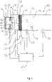
- the 1 shows a basic representation of the structure of a fuel-powered vehicle heater, generally designated 10.
- the vehicle heater 10 comprises a burner area 12 with a combustion chamber 14 formed in a combustion chamber housing.
- a porous evaporator medium 16 is provided on a floor area delimiting the combustion chamber 14 when the burner area 12 is constructed as an evaporative burner, which medium can be embodied, for example, as a metal mesh, knitted metal fabric, ceramic foam or the like .
- the porous evaporator medium 16 can be assigned an electrically excitable heating device 18 .
- the fuel required for the combustion is introduced into the porous evaporator medium 16 via a fuel line 22 by means of a fuel pump 20 , for example a metering pump.
- the liquid fuel is distributed in the evaporator medium 16 by the capillary conveying effect and is discharged into the combustion chamber 14 as fuel vapor, ie in the gaseous state of aggregation.
- the combustion air required for the combustion is conveyed to the combustion chamber 14 by a combustion air blower, generally designated 24 .
- the combustion air discharged from the combustion air fan 24 enters a space 26, generally referred to as a plenum, upstream of the combustion chamber 14 and enters the combustion chamber 14 via a plurality of, for example, a peripheral wall delimiting the combustion chamber 14 and/or an air inlet nozzle provided in the floor area.
- the mixture of combustion air and fuel formed in the combustion chamber 14 is ignited, for example, by an electrically excitable ignition element 28, for example a glow plug.
- the exhaust gases produced during the combustion leave the combustion chamber 14 via a flame screen 29 and flow along a flame tube 30 in the direction of a heat exchanger area (not shown).
- the vehicle heater 10 also has a control arrangement, generally designated 32 .
- This controls the operation of the fuel pump 20 and the combustion air fan 24 as well as the electrically excitable heating device 18.
- the control arrangement 32 of various sensors such. B. a pressure sensor 34 and a temperature sensor 36, for the operation of the vehicle heater 10 relevant information is supplied.
- the combustion air fan 24 is generally constructed as a so-called side channel fan. It comprises a fan housing 38 with a bottom wall 42 which together with a peripheral wall 40 delimits an air flow space 44 .
- a fan housing 38 On the The combustion air to be conveyed in the direction of the combustion chamber 14 reaches an annular conveying channel 46 formed in the bottom wall 42 in the air flow space 44. This is covered on an outside of the bottom wall 42 facing away from the air flow space 44 by a conveying wheel 48 which is only shown in principle and can be rotated about an axis of rotation D. In the conveying mode, the air conveyed along the conveying channel 46 by the conveying effect of the rotating conveying wheel 48 enters the space 26 and via this into the combustion chamber 14 .
- the air to be conveyed to the burner area 12 reaches the air flow space 44 via an inlet opening 50 .
- the air leaves the air flow space 44 surrounding the axis of rotation D via an outlet opening 52 and enters the conveying channel 46 .
- the air flow space 44 is therefore upstream of the conveying channel 46.
- a motor housing area 54 is provided on the fan housing 38 to accommodate a fan motor which drives the feed wheel 48 and which is generally designed as an electric motor.
- This includes a peripheral wall and a bottom wall provided on the end of the peripheral wall facing away from the bottom wall 42 of the fan housing 38 .
- the peripheral wall of the motor housing portion, together with the bottom wall 42 and, as discussed below, a portion of the peripheral wall 40 of the fan housing 38 may be formed as an integral component, particularly a metal casting such as aluminum or an aluminum alloy.
- the bottom wall of the motor housing area can be attached at the axial end, axially in relation to an axis of rotation of a rotor shaft of the fan motor or the axis of rotation D of conveyor wheel 48, of the peripheral wall of the motor housing area, for example by screwing, latching or the like can be specified.
- a closing element In order to also close off the air flow space 44 at the end region of the peripheral wall 40 of the fan housing 38 facing away from the bottom wall 42 , a closing element, generally designated 60, is provided. This can have a plurality of locking tabs on corresponding locking projections on the Peripheral wall 40 are locked.
- the control arrangement 32 or at least a part thereof, z. B. the part serving to control the blower motor can be provided, with an electrical connection to the blower motor being able to be made, for example, via a plug-in area engaging in the air flow space 44 .
- hydrocarbon storage elements 62 , 64 can be provided in the air flow space, for example adjacent to the peripheral wall 40 , the base wall 42 or the closing element 60 . These can be constructed with material containing activated carbon and can be accommodated, for example, as one or more blocks of material in the air flow space 44 .
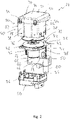
- combustion air fan 24 The structure of the combustion air fan 24 is described below with reference to FIG 2 described in detail.
- the 2 shows the combustion air fan 24 in an exploded view.
- a central component is formed by the fan housing 38 with the bottom wall 42 provided thereon as an integral component.
- This or the conveyor channel 46 formed therein is covered by the conveyor wheel 48 .
- the motor housing area 54 with its peripheral wall 66 and a bottom wall 68 to be attached thereto is provided on the side of the bottom wall 42 oriented towards the air flow space 42 .
- At least the peripheral wall 66 may also form an integral part of the fan housing 38 .
- a housing cover generally designated 70 This covers a delivery area 72 of the combustion air fan 24.
- the delivery area 72 essentially comprises the delivery wheel 48 and the delivery channel 46 covered by it.
- the housing cover 70 provides a hood area 74 which essentially covers the bottom wall 42 and closes the delivery area 72.
- a ring-like sealing element 76 can be positioned between the bottom wall 42 and the housing cover 70 so as to surround the delivery wheel 48 or the delivery channel 46 .
- a first part 78 of the peripheral wall 40 surrounding the axis of rotation D or extending in the direction of the axis of rotation D forms an integral part of the fan housing 48 and extends from the bottom wall 42 on the side thereof remote from the impeller 48 .
- An air supply channel 80 is formed on this first part 78 of the peripheral wall 40 and is open to the air flow space 44 via the inlet opening 50 .
- a second part 82 of the peripheral wall 40 is formed on the housing cover 70 . This second part 82, together with the first part 80, completely surrounds the air flow space 44 in the circumferential direction.
- the peripheral wall 40 is provided with a total of four partial peripheral walls 84, 86, 88, 90.
- the partial peripheral wall 44 essentially provides the first portion 78 of the peripheral wall 40 and thus forms an integral part of the fan housing 38.
- the partial peripheral walls 86, 88, 90 essentially provide the second portion 82 of the peripheral wall 40 and together form the hood area 74 is an integral part of the housing cover 70.
- the housing cover 70 can be attached to the fan housing 38, for example, by positioning latching elements 92 integrally formed on the fan housing 38, engaging in associated latching openings 94 on the housing cover 70, and thus maintaining the connection between the housing cover 70 and the fan housing 38 by positive locking.
- the partial peripheral walls 86, 90 then connect to the partial peripheral wall 84.
- groove-like recesses can be provided in the first part 78 of the peripheral wall 40, in which peripheral edge regions of the partial peripheral walls 86, 90 are positioned to engage.
- latching tabs 96 into which latching projections 98 provided on the second part 82 of the peripheral wall 40 can be positioned to engage, in order to also ensure a firm cohesion generated by positive locking.
- one or more hydrocarbon storage elements may be positioned within the airflow space 44 prior to attachment of the closure member 60, for example.
- a significant part of the peripheral wall 40 is no longer made of the heavier structural material of the fan housing 38, i.e. no longer with metal material is constructed, but with the lighter construction material of the housing cover 70, so a plastic material.
- a particularly suitable plastic material can be polyamide material, such as. B. PA6 GF30, can be used, i.e. a polyamide material that is reinforced with a glass fiber content of 30%.
- a corresponding construction material can also be used for the closing element 60 .
- the housing cover 70 or the closing element 60 can be produced in an injection molding process.
- the MuCell® method can be used particularly advantageously here, in which very good acoustic damping can be achieved due to the formation of a microcellular core.
- the fan housing 38 is made of metal material, such as, in a die-casting process e.g. As aluminum or an aluminum alloy constructed. It is preferably provided that on the first part 78 of the peripheral wall 40, i.e. the partial peripheral wall 84, on the outside facing away from the air flow edge 44, the burner region 12 of the in 2 is arranged or attached in a basic manner illustrated vehicle heater 10. Thus, this burner area, which leads to greater thermal and mechanical stress, is connected to the combustion air fan 24 via a component made of metal material that is less sensitive in this respect.
- the combustion air fan described above can of course be varied, particularly with regard to the design of the peripheral wall.
- the entire peripheral wall could be provided on the housing cover 74 and thus made of plastic material.
- the fan housing would then essentially also include the bottom wall to be inserted into the housing cover and the motor housing area provided on it.
- part of the partial peripheral walls 86, 90 of the second part of the peripheral wall 40 could extend from the first part 78, ie the partial peripheral wall 84, and thus be provided as part of the fan housing 38.
Landscapes
- Engineering & Computer Science (AREA)
- Mechanical Engineering (AREA)
- General Engineering & Computer Science (AREA)
- Physics & Mathematics (AREA)
- Thermal Sciences (AREA)
- Chemical & Material Sciences (AREA)
- Combustion & Propulsion (AREA)
- Structures Of Non-Positive Displacement Pumps (AREA)
- Air-Conditioning For Vehicles (AREA)
Claims (14)
- Ventilateur d'air de combustion, en particulier ventilateur à canal latéral, pour un chauffage de véhicule alimenté en carburant, comprenant un boîtier de ventilateur (38), dans lequel une chambre d'écoulement d'air (44) pouvant être traversée par l'air de combustion à transporter est formée sur le boîtier de ventilateur (38) et l'air entrant dans la chambre d'écoulement d'air (44) par au moins une ouverture d'entrée (50) s'écoule vers une zone de transport (72) comprenant une roue de transport (48) pouvant tourner autour d'un axe de rotation (D), dans lequel le boîtier de ventilateur (38) comprend une paroi de fond (42) et la région de transport (72) dans la paroi de fond (42) du boîtier de ventilateur (38) comprend un canal de transport (46) ouvert vers un côté extérieur opposé à la chambre d'écoulement d'air (44), entourant l'axe de rotation de manière annulaire et recouvert par la roue de transport (48), dans lequel la chambre d'écoulement d'air (44) est ouverte vers le canal de transport (46) par au moins une ouverture de sortie (52), dans lequel un couvercle de boîtier (70) est porté sur le boîtier de ventilateur (38), recouvrant la roue de transport (48) et définissant avec le boîtier de ventilateur (38) un espace de réception de la roue de transport, comprenant en outre une paroi circonférentielle (40) entourant la chambre d'écoulement d'air (44), caractérisé en ce qu'au moins une partie de la paroi circonférentielle (40) est formée sur le couvercle de boîtier (70).
- Ventilateur d'air de combustion selon la revendication 1, caractérisée en ce qu'une première partie (78) de la paroi circonférentielle (40) est formée sur le boîtier de ventilateur (38) et une deuxième partie (82) de la paroi circonférentielle (40) est formée sur le couvercle de boîtier (70).
- Ventilateur d'air de combustion selon l'une des revendications précédentes, caractérisée en ce que la paroi circonférentielle (40) présente une géométrie de section transversale sensiblement rectangulaire pourvue de quatre parois circonférentielles partielles (84, 86, 88, 90), et en ce qu'une des parois circonférentielles partielles (84, 86, 88, 90) est prévue sur le boîtier de ventilateur (38) et trois des parois circonférentielles partielles (84, 86, 88, 90) sont prévues sur le couvercle de boîtier (70).
- Ventilateur d'air de combustion selon l'une des revendications précédentes, caractérisée en ce qu'un canal d'amenée d'air (80) menant à la chambre d'écoulement d'air (44) et ouvert sur celle-ci via ladite au moins une ouverture d'entrée (50) est prévu dans la première partie (78) de la paroi circonférentielle (40).
- Ventilateur d'air de combustion selon l'une des revendications précédentes, caractérisée en ce que le boîtier de ventilateur (38) présente une zone de boîtier moteur (54) qui est entourée au moins par zones par la chambre d'écoulement d'air (44) et qui présente une paroi circonférentielle (66) et une paroi de fond (68).
- Ventilateur d'air de combustion selon l'une des revendications précédentes, caractérisée en ce qu'un élément de fermeture (60) fermant la chambre d'écoulement d'air (44) est prévu sur une zone d'extrémité de la paroi circonférentielle (40) opposée à la paroi de fond (42) du boîtier de ventilateur (38), et en ce que l'élément de fermeture (60) est réalisé en matière plastique.
- Ventilateur d'air de combustion selon l'une des revendications précédentes, caractérisée en ce qu'un élément d'étanchéité (76) fermant hermétiquement l'espace de réception de la roue de transport dans la zone de la jonction du couvercle de boîtier (70) avec la paroi de fond (42) est disposé entre le couvercle de boîtier (70) et la paroi de fond (42) du boîtier de ventilateur (38).
- Ventilateur d'air de combustion selon la revendication 7, caractérisée en ce que l'élément d'étanchéité (76) est disposé sur un côté extérieur de la paroi de fond (42) du boîtier de ventilateur (38) pour entourer de manière annulaire le canal de transport (46).
- Ventilateur d'air de combustion selon l'une des revendications précédentes, caractérisée en ce qu'au moins un élément de stockage d'hydrocarbures (62, 64) est disposé dans la chambre d'écoulement d'air (44).
- Ventilateur d'air de combustion selon la revendication 9, caractérisée en ce qu'au moins un élément de stockage d'hydrocarbures (62, 64) est réalisé avec un matériau contenant du charbon actif.
- Ventilateur d'air de combustion selon l'une quelconque des revendications précédentes, caractérisée en ce que le boîtier de ventilateur (38) est construit en matériau métallique, de préférence en aluminium ou en alliage d'aluminium, et en ce que le couvercle de boîtier (70) est construit en matériau plastique, de préférence en matériau polyamide.
- Ventilateur d'air de combustion selon la revendication 1 ou 2, caractérisée en ce que le boîtier de ventilateur (38) est fabriqué dans un procédé de moulage sous pression de métal, ou/et que le couvercle de boîtier (70) est fabriqué dans un procédé de moulage par injection de plastique, de préférence un procédé de moulage par injection MuCell@.
- Appareil de chauffage de véhicule fonctionnant au carburant, comprenant une zone de brûleur (12), une pompe à carburant (20) transportant du carburant liquide vers la zone de brûleur (12), et un ventilateur d'air de combustion (24) selon l'une des revendications précédentes.
- Appareil de chauffage de véhicule alimenté en carburant selon la revendication 13, lorsqu'on renvoie à la revendication 2, caractérisé en ce que la partie brûleur (12) est supportée sur la première partie (78) de la paroi circonférentielle (40).
Applications Claiming Priority (1)
| Application Number | Priority Date | Filing Date | Title |
|---|---|---|---|
| DE102018107953.2A DE102018107953A1 (de) | 2018-04-04 | 2018-04-04 | Verbrennungsluftgebläse |
Publications (2)
| Publication Number | Publication Date |
|---|---|
| EP3550151A1 EP3550151A1 (fr) | 2019-10-09 |
| EP3550151B1 true EP3550151B1 (fr) | 2022-09-14 |
Family
ID=66049044
Family Applications (1)
| Application Number | Title | Priority Date | Filing Date |
|---|---|---|---|
| EP19166497.8A Active EP3550151B1 (fr) | 2018-04-04 | 2019-04-01 | Ventilateur à air de combustion |
Country Status (5)
| Country | Link |
|---|---|
| EP (1) | EP3550151B1 (fr) |
| CN (1) | CN110341435B (fr) |
| DE (1) | DE102018107953A1 (fr) |
| PL (1) | PL3550151T3 (fr) |
| RU (1) | RU2711443C1 (fr) |
Family Cites Families (10)
| Publication number | Priority date | Publication date | Assignee | Title |
|---|---|---|---|---|
| US3360193A (en) * | 1965-12-29 | 1967-12-26 | Rotron Mfg Co | Regenerative compressors with integral mufflers |
| KR910012551A (ko) * | 1989-09-14 | 1991-08-08 | 이다가끼 유끼오 | 송풍기 |
| DE19909507C1 (de) * | 1999-03-04 | 2000-11-16 | Temic Auto Electr Motors Gmbh | Radialgebläse, insbesondere für Heizungs- und Klimaanlagen |
| DE10110560B4 (de) * | 2001-03-05 | 2009-11-26 | Webasto Ag | Fahrzeug-Heizgerät |
| DE102010041139B4 (de) * | 2010-09-21 | 2018-03-29 | Eberspächer Climate Control Systems GmbH & Co. KG | Seitenkanalgebläse für ein Fahrzeugheizgerät |
| DE102012213598B3 (de) * | 2012-08-01 | 2013-11-14 | Eberspächer Climate Control Systems GmbH & Co. KG | Gebläse, insbesondere Verbrennungsluftgebläse für ein Fahrzeugheizgerät |
| DE102015102340B4 (de) * | 2015-02-19 | 2022-02-03 | Eberspächer Climate Control Systems GmbH | Gebläsegehäuse, insbesondere für ein Verbrennungsluftgebläse eines Fahrzeugheizgeräts |
| DE102016109994A1 (de) * | 2016-05-31 | 2017-11-30 | Eberspächer Climate Control Systems GmbH & Co. KG | Seitenkanalgebläse, insbesondere für ein Fahrzeugheizgerät |
| DE102016117408B4 (de) * | 2016-09-15 | 2020-11-26 | Eberspächer Climate Control Systems GmbH | Brennkammerbaugruppe für ein brennstoffbetriebenes Fahrzeugheizgerät |
| DE102017114762A1 (de) * | 2017-07-03 | 2019-01-03 | Eberspächer Climate Control Systems GmbH & Co. KG | Trägeranordnung |
-
2018
- 2018-04-04 DE DE102018107953.2A patent/DE102018107953A1/de not_active Ceased
-
2019
- 2019-03-26 CN CN201910229744.3A patent/CN110341435B/zh active Active
- 2019-04-01 EP EP19166497.8A patent/EP3550151B1/fr active Active
- 2019-04-01 PL PL19166497.8T patent/PL3550151T3/pl unknown
- 2019-04-03 RU RU2019109732A patent/RU2711443C1/ru active
Also Published As
| Publication number | Publication date |
|---|---|
| RU2711443C1 (ru) | 2020-01-17 |
| DE102018107953A1 (de) | 2019-10-10 |
| EP3550151A1 (fr) | 2019-10-09 |
| CN110341435B (zh) | 2023-02-03 |
| CN110341435A (zh) | 2019-10-18 |
| PL3550151T3 (pl) | 2023-01-30 |
Similar Documents
| Publication | Publication Date | Title |
|---|---|---|
| EP0803027B1 (fr) | Dispositif d'injection de carburant pour moteur a combustion interne | |
| DE2843534C2 (de) | Kraftstoffliefereinrichtung für eine Brennkraftmaschine | |
| EP1860379B1 (fr) | Composant d'évaporateur, en particulier pour un appareil de chauffage de véhicule ou un dispositif de réformateur de carburant d'un système à cellules combustibles | |
| EP3401594B1 (fr) | Appareil chauffant pour véhicule | |
| DE102017125783A1 (de) | Fahrzeugheizgerät | |
| EP3534010B1 (fr) | Ventilateur d'air de combustion | |
| EP3550151B1 (fr) | Ventilateur à air de combustion | |
| DE10255361B3 (de) | Brennkammerbaugruppe für ein Heizgerät, insbesondere Fahrzeugheizgerät | |
| DE102011084868B4 (de) | Verdampferbrenner, insbesondere für ein Fahrzeugheizgerät | |
| DE4100523C2 (fr) | ||
| EP1867922B1 (fr) | Composant d évaporateur pour un brûleur à évaporation, en particulier pour un chauffage de véhicule ou un chauffage de bâtiment | |
| EP1839921B1 (fr) | Appareil de chauffage pour véhicule | |
| EP1927489B1 (fr) | Appareil de chauffage pour véhicule | |
| EP2012058A2 (fr) | Appareil de chauffage pour véhicule | |
| DE19504180C2 (de) | Heizgerät für insbesondere Fahrzeuge | |
| EP1788305B1 (fr) | Ensemble de chambre de combustion pour un brûleur à évaporation | |
| DE102012220789A1 (de) | Wärmetauscheranordnung, insbesondere für ein Fahrzeugheizgerät | |
| EP1925477B1 (fr) | Appareil de chauffage pour véhicule | |
| EP2026001B1 (fr) | Agencement d'admission d'air d'allumage pour un composant de chambre à combustion d'un appareil de chauffage à combustible, en particulier appareil de chauffage de véhicule | |
| DE102017108151B4 (de) | Verbrennungsluftgebläse und Fahrzeugheizgerät mit einem derartigen Verbrennungsluftgebläse | |
| DE102020106881A1 (de) | Brennkammerbaugruppe für ein brennstoffbetriebenes Fahrzeugheizgerät | |
| EP1927488B1 (fr) | Appareil de chauffage pour véhicule | |
| DE102011051044B3 (de) | Brennkammeranordnung | |
| EP1482242B1 (fr) | Disposition d'une chambre de combustion | |
| DE10207953A1 (de) | Heizgerät, insbesondere für ein Fahrzeug |
Legal Events
| Date | Code | Title | Description |
|---|---|---|---|
| PUAI | Public reference made under article 153(3) epc to a published international application that has entered the european phase |
Free format text: ORIGINAL CODE: 0009012 |
|
| STAA | Information on the status of an ep patent application or granted ep patent |
Free format text: STATUS: THE APPLICATION HAS BEEN PUBLISHED |
|
| AK | Designated contracting states |
Kind code of ref document: A1 Designated state(s): AL AT BE BG CH CY CZ DE DK EE ES FI FR GB GR HR HU IE IS IT LI LT LU LV MC MK MT NL NO PL PT RO RS SE SI SK SM TR |
|
| AX | Request for extension of the european patent |
Extension state: BA ME |
|
| STAA | Information on the status of an ep patent application or granted ep patent |
Free format text: STATUS: REQUEST FOR EXAMINATION WAS MADE |
|
| 17P | Request for examination filed |
Effective date: 20200409 |
|
| RBV | Designated contracting states (corrected) |
Designated state(s): AL AT BE BG CH CY CZ DE DK EE ES FI FR GB GR HR HU IE IS IT LI LT LU LV MC MK MT NL NO PL PT RO RS SE SI SK SM TR |
|
| RAP1 | Party data changed (applicant data changed or rights of an application transferred) |
Owner name: EBERSPAECHER CLIMATE CONTROL SYSTEMS GMBH |
|
| GRAP | Despatch of communication of intention to grant a patent |
Free format text: ORIGINAL CODE: EPIDOSNIGR1 |
|
| STAA | Information on the status of an ep patent application or granted ep patent |
Free format text: STATUS: GRANT OF PATENT IS INTENDED |
|
| INTG | Intention to grant announced |
Effective date: 20220623 |
|
| GRAS | Grant fee paid |
Free format text: ORIGINAL CODE: EPIDOSNIGR3 |
|
| GRAA | (expected) grant |
Free format text: ORIGINAL CODE: 0009210 |
|
| STAA | Information on the status of an ep patent application or granted ep patent |
Free format text: STATUS: THE PATENT HAS BEEN GRANTED |
|
| AK | Designated contracting states |
Kind code of ref document: B1 Designated state(s): AL AT BE BG CH CY CZ DE DK EE ES FI FR GB GR HR HU IE IS IT LI LT LU LV MC MK MT NL NO PL PT RO RS SE SI SK SM TR |
|
| REG | Reference to a national code |
Ref country code: GB Ref legal event code: FG4D Free format text: NOT ENGLISH |
|
| REG | Reference to a national code |
Ref country code: CH Ref legal event code: EP |
|
| REG | Reference to a national code |
Ref country code: DE Ref legal event code: R096 Ref document number: 502019005640 Country of ref document: DE |
|
| REG | Reference to a national code |
Ref country code: IE Ref legal event code: FG4D Free format text: LANGUAGE OF EP DOCUMENT: GERMAN |
|
| REG | Reference to a national code |
Ref country code: AT Ref legal event code: REF Ref document number: 1518845 Country of ref document: AT Kind code of ref document: T Effective date: 20221015 |
|
| REG | Reference to a national code |
Ref country code: LT Ref legal event code: MG9D |
|
| REG | Reference to a national code |
Ref country code: NL Ref legal event code: MP Effective date: 20220914 |
|
| PG25 | Lapsed in a contracting state [announced via postgrant information from national office to epo] |
Ref country code: SE Free format text: LAPSE BECAUSE OF FAILURE TO SUBMIT A TRANSLATION OF THE DESCRIPTION OR TO PAY THE FEE WITHIN THE PRESCRIBED TIME-LIMIT Effective date: 20220914 Ref country code: RS Free format text: LAPSE BECAUSE OF FAILURE TO SUBMIT A TRANSLATION OF THE DESCRIPTION OR TO PAY THE FEE WITHIN THE PRESCRIBED TIME-LIMIT Effective date: 20220914 Ref country code: NO Free format text: LAPSE BECAUSE OF FAILURE TO SUBMIT A TRANSLATION OF THE DESCRIPTION OR TO PAY THE FEE WITHIN THE PRESCRIBED TIME-LIMIT Effective date: 20221214 Ref country code: LV Free format text: LAPSE BECAUSE OF FAILURE TO SUBMIT A TRANSLATION OF THE DESCRIPTION OR TO PAY THE FEE WITHIN THE PRESCRIBED TIME-LIMIT Effective date: 20220914 Ref country code: LT Free format text: LAPSE BECAUSE OF FAILURE TO SUBMIT A TRANSLATION OF THE DESCRIPTION OR TO PAY THE FEE WITHIN THE PRESCRIBED TIME-LIMIT Effective date: 20220914 Ref country code: FI Free format text: LAPSE BECAUSE OF FAILURE TO SUBMIT A TRANSLATION OF THE DESCRIPTION OR TO PAY THE FEE WITHIN THE PRESCRIBED TIME-LIMIT Effective date: 20220914 |
|
| PG25 | Lapsed in a contracting state [announced via postgrant information from national office to epo] |
Ref country code: HR Free format text: LAPSE BECAUSE OF FAILURE TO SUBMIT A TRANSLATION OF THE DESCRIPTION OR TO PAY THE FEE WITHIN THE PRESCRIBED TIME-LIMIT Effective date: 20220914 Ref country code: GR Free format text: LAPSE BECAUSE OF FAILURE TO SUBMIT A TRANSLATION OF THE DESCRIPTION OR TO PAY THE FEE WITHIN THE PRESCRIBED TIME-LIMIT Effective date: 20221215 |
|
| PG25 | Lapsed in a contracting state [announced via postgrant information from national office to epo] |
Ref country code: SM Free format text: LAPSE BECAUSE OF FAILURE TO SUBMIT A TRANSLATION OF THE DESCRIPTION OR TO PAY THE FEE WITHIN THE PRESCRIBED TIME-LIMIT Effective date: 20220914 Ref country code: RO Free format text: LAPSE BECAUSE OF FAILURE TO SUBMIT A TRANSLATION OF THE DESCRIPTION OR TO PAY THE FEE WITHIN THE PRESCRIBED TIME-LIMIT Effective date: 20220914 Ref country code: PT Free format text: LAPSE BECAUSE OF FAILURE TO SUBMIT A TRANSLATION OF THE DESCRIPTION OR TO PAY THE FEE WITHIN THE PRESCRIBED TIME-LIMIT Effective date: 20230116 Ref country code: ES Free format text: LAPSE BECAUSE OF FAILURE TO SUBMIT A TRANSLATION OF THE DESCRIPTION OR TO PAY THE FEE WITHIN THE PRESCRIBED TIME-LIMIT Effective date: 20220914 |
|
| PG25 | Lapsed in a contracting state [announced via postgrant information from national office to epo] |
Ref country code: SK Free format text: LAPSE BECAUSE OF FAILURE TO SUBMIT A TRANSLATION OF THE DESCRIPTION OR TO PAY THE FEE WITHIN THE PRESCRIBED TIME-LIMIT Effective date: 20220914 Ref country code: IS Free format text: LAPSE BECAUSE OF FAILURE TO SUBMIT A TRANSLATION OF THE DESCRIPTION OR TO PAY THE FEE WITHIN THE PRESCRIBED TIME-LIMIT Effective date: 20230114 Ref country code: EE Free format text: LAPSE BECAUSE OF FAILURE TO SUBMIT A TRANSLATION OF THE DESCRIPTION OR TO PAY THE FEE WITHIN THE PRESCRIBED TIME-LIMIT Effective date: 20220914 |
|
| REG | Reference to a national code |
Ref country code: DE Ref legal event code: R097 Ref document number: 502019005640 Country of ref document: DE |
|
| PG25 | Lapsed in a contracting state [announced via postgrant information from national office to epo] |
Ref country code: NL Free format text: LAPSE BECAUSE OF FAILURE TO SUBMIT A TRANSLATION OF THE DESCRIPTION OR TO PAY THE FEE WITHIN THE PRESCRIBED TIME-LIMIT Effective date: 20220914 Ref country code: AL Free format text: LAPSE BECAUSE OF FAILURE TO SUBMIT A TRANSLATION OF THE DESCRIPTION OR TO PAY THE FEE WITHIN THE PRESCRIBED TIME-LIMIT Effective date: 20220914 |
|
| PLBE | No opposition filed within time limit |
Free format text: ORIGINAL CODE: 0009261 |
|
| STAA | Information on the status of an ep patent application or granted ep patent |
Free format text: STATUS: NO OPPOSITION FILED WITHIN TIME LIMIT |
|
| PG25 | Lapsed in a contracting state [announced via postgrant information from national office to epo] |
Ref country code: DK Free format text: LAPSE BECAUSE OF FAILURE TO SUBMIT A TRANSLATION OF THE DESCRIPTION OR TO PAY THE FEE WITHIN THE PRESCRIBED TIME-LIMIT Effective date: 20220914 |
|
| 26N | No opposition filed |
Effective date: 20230615 |
|
| PG25 | Lapsed in a contracting state [announced via postgrant information from national office to epo] |
Ref country code: SI Free format text: LAPSE BECAUSE OF FAILURE TO SUBMIT A TRANSLATION OF THE DESCRIPTION OR TO PAY THE FEE WITHIN THE PRESCRIBED TIME-LIMIT Effective date: 20220914 |
|
| REG | Reference to a national code |
Ref country code: CH Ref legal event code: PL |
|
| GBPC | Gb: european patent ceased through non-payment of renewal fee |
Effective date: 20230401 |
|
| PG25 | Lapsed in a contracting state [announced via postgrant information from national office to epo] |
Ref country code: LU Free format text: LAPSE BECAUSE OF NON-PAYMENT OF DUE FEES Effective date: 20230401 |
|
| REG | Reference to a national code |
Ref country code: BE Ref legal event code: MM Effective date: 20230430 |
|
| PG25 | Lapsed in a contracting state [announced via postgrant information from national office to epo] |
Ref country code: MC Free format text: LAPSE BECAUSE OF FAILURE TO SUBMIT A TRANSLATION OF THE DESCRIPTION OR TO PAY THE FEE WITHIN THE PRESCRIBED TIME-LIMIT Effective date: 20220914 |
|
| PG25 | Lapsed in a contracting state [announced via postgrant information from national office to epo] |
Ref country code: GB Free format text: LAPSE BECAUSE OF NON-PAYMENT OF DUE FEES Effective date: 20230401 |
|
| PG25 | Lapsed in a contracting state [announced via postgrant information from national office to epo] |
Ref country code: MC Free format text: LAPSE BECAUSE OF FAILURE TO SUBMIT A TRANSLATION OF THE DESCRIPTION OR TO PAY THE FEE WITHIN THE PRESCRIBED TIME-LIMIT Effective date: 20220914 Ref country code: LI Free format text: LAPSE BECAUSE OF NON-PAYMENT OF DUE FEES Effective date: 20230430 Ref country code: GB Free format text: LAPSE BECAUSE OF NON-PAYMENT OF DUE FEES Effective date: 20230401 Ref country code: CH Free format text: LAPSE BECAUSE OF NON-PAYMENT OF DUE FEES Effective date: 20230430 |
|
| REG | Reference to a national code |
Ref country code: IE Ref legal event code: MM4A |
|
| PG25 | Lapsed in a contracting state [announced via postgrant information from national office to epo] |
Ref country code: BE Free format text: LAPSE BECAUSE OF NON-PAYMENT OF DUE FEES Effective date: 20230430 |
|
| PG25 | Lapsed in a contracting state [announced via postgrant information from national office to epo] |
Ref country code: IE Free format text: LAPSE BECAUSE OF NON-PAYMENT OF DUE FEES Effective date: 20230401 |
|
| PG25 | Lapsed in a contracting state [announced via postgrant information from national office to epo] |
Ref country code: IE Free format text: LAPSE BECAUSE OF NON-PAYMENT OF DUE FEES Effective date: 20230401 |
|
| PG25 | Lapsed in a contracting state [announced via postgrant information from national office to epo] |
Ref country code: IT Free format text: LAPSE BECAUSE OF FAILURE TO SUBMIT A TRANSLATION OF THE DESCRIPTION OR TO PAY THE FEE WITHIN THE PRESCRIBED TIME-LIMIT Effective date: 20220914 |
|
| PG25 | Lapsed in a contracting state [announced via postgrant information from national office to epo] |
Ref country code: BG Free format text: LAPSE BECAUSE OF FAILURE TO SUBMIT A TRANSLATION OF THE DESCRIPTION OR TO PAY THE FEE WITHIN THE PRESCRIBED TIME-LIMIT Effective date: 20220914 |
|
| PG25 | Lapsed in a contracting state [announced via postgrant information from national office to epo] |
Ref country code: BG Free format text: LAPSE BECAUSE OF FAILURE TO SUBMIT A TRANSLATION OF THE DESCRIPTION OR TO PAY THE FEE WITHIN THE PRESCRIBED TIME-LIMIT Effective date: 20220914 |
|
| PGFP | Annual fee paid to national office [announced via postgrant information from national office to epo] |
Ref country code: PL Payment date: 20250325 Year of fee payment: 7 Ref country code: CZ Payment date: 20250321 Year of fee payment: 7 |
|
| REG | Reference to a national code |
Ref country code: AT Ref legal event code: MM01 Ref document number: 1518845 Country of ref document: AT Kind code of ref document: T Effective date: 20240401 |
|
| PGFP | Annual fee paid to national office [announced via postgrant information from national office to epo] |
Ref country code: DE Payment date: 20250417 Year of fee payment: 7 |
|
| PGFP | Annual fee paid to national office [announced via postgrant information from national office to epo] |
Ref country code: FR Payment date: 20250422 Year of fee payment: 7 |
|
| PG25 | Lapsed in a contracting state [announced via postgrant information from national office to epo] |
Ref country code: AT Free format text: LAPSE BECAUSE OF NON-PAYMENT OF DUE FEES Effective date: 20240401 |
|
| PG25 | Lapsed in a contracting state [announced via postgrant information from national office to epo] |
Ref country code: CY Free format text: LAPSE BECAUSE OF FAILURE TO SUBMIT A TRANSLATION OF THE DESCRIPTION OR TO PAY THE FEE WITHIN THE PRESCRIBED TIME-LIMIT; INVALID AB INITIO Effective date: 20190401 |
|
| PG25 | Lapsed in a contracting state [announced via postgrant information from national office to epo] |
Ref country code: HU Free format text: LAPSE BECAUSE OF FAILURE TO SUBMIT A TRANSLATION OF THE DESCRIPTION OR TO PAY THE FEE WITHIN THE PRESCRIBED TIME-LIMIT; INVALID AB INITIO Effective date: 20190401 |
|
| PG25 | Lapsed in a contracting state [announced via postgrant information from national office to epo] |
Ref country code: TR Free format text: LAPSE BECAUSE OF FAILURE TO SUBMIT A TRANSLATION OF THE DESCRIPTION OR TO PAY THE FEE WITHIN THE PRESCRIBED TIME-LIMIT Effective date: 20220914 |