EP3546274A1 - Fahrzeug, steigungsassistenzsystem für fahrzeug und steuerungsverfahren dafür - Google Patents
Fahrzeug, steigungsassistenzsystem für fahrzeug und steuerungsverfahren dafür Download PDFInfo
- Publication number
- EP3546274A1 EP3546274A1 EP17874203.7A EP17874203A EP3546274A1 EP 3546274 A1 EP3546274 A1 EP 3546274A1 EP 17874203 A EP17874203 A EP 17874203A EP 3546274 A1 EP3546274 A1 EP 3546274A1
- Authority
- EP
- European Patent Office
- Prior art keywords
- vehicle
- auxiliary system
- ramp
- ramp auxiliary
- torque
- Prior art date
- Legal status (The legal status is an assumption and is not a legal conclusion. Google has not performed a legal analysis and makes no representation as to the accuracy of the status listed.)
- Withdrawn
Links
Images


Classifications
-
- B—PERFORMING OPERATIONS; TRANSPORTING
- B60—VEHICLES IN GENERAL
- B60L—PROPULSION OF ELECTRICALLY-PROPELLED VEHICLES; SUPPLYING ELECTRIC POWER FOR AUXILIARY EQUIPMENT OF ELECTRICALLY-PROPELLED VEHICLES; ELECTRODYNAMIC BRAKE SYSTEMS FOR VEHICLES IN GENERAL; MAGNETIC SUSPENSION OR LEVITATION FOR VEHICLES; MONITORING OPERATING VARIABLES OF ELECTRICALLY-PROPELLED VEHICLES; ELECTRIC SAFETY DEVICES FOR ELECTRICALLY-PROPELLED VEHICLES
- B60L15/00—Methods, circuits, or devices for controlling the traction-motor speed of electrically-propelled vehicles
- B60L15/20—Methods, circuits, or devices for controlling the traction-motor speed of electrically-propelled vehicles for control of the vehicle or its driving motor to achieve a desired performance, e.g. speed, torque, programmed variation of speed
- B60L15/2072—Methods, circuits, or devices for controlling the traction-motor speed of electrically-propelled vehicles for control of the vehicle or its driving motor to achieve a desired performance, e.g. speed, torque, programmed variation of speed for drive off
- B60L15/2081—Methods, circuits, or devices for controlling the traction-motor speed of electrically-propelled vehicles for control of the vehicle or its driving motor to achieve a desired performance, e.g. speed, torque, programmed variation of speed for drive off for drive off on a slope
-
- B—PERFORMING OPERATIONS; TRANSPORTING
- B60—VEHICLES IN GENERAL
- B60L—PROPULSION OF ELECTRICALLY-PROPELLED VEHICLES; SUPPLYING ELECTRIC POWER FOR AUXILIARY EQUIPMENT OF ELECTRICALLY-PROPELLED VEHICLES; ELECTRODYNAMIC BRAKE SYSTEMS FOR VEHICLES IN GENERAL; MAGNETIC SUSPENSION OR LEVITATION FOR VEHICLES; MONITORING OPERATING VARIABLES OF ELECTRICALLY-PROPELLED VEHICLES; ELECTRIC SAFETY DEVICES FOR ELECTRICALLY-PROPELLED VEHICLES
- B60L15/00—Methods, circuits, or devices for controlling the traction-motor speed of electrically-propelled vehicles
- B60L15/20—Methods, circuits, or devices for controlling the traction-motor speed of electrically-propelled vehicles for control of the vehicle or its driving motor to achieve a desired performance, e.g. speed, torque, programmed variation of speed
- B60L15/2009—Methods, circuits, or devices for controlling the traction-motor speed of electrically-propelled vehicles for control of the vehicle or its driving motor to achieve a desired performance, e.g. speed, torque, programmed variation of speed for braking
- B60L15/2018—Methods, circuits, or devices for controlling the traction-motor speed of electrically-propelled vehicles for control of the vehicle or its driving motor to achieve a desired performance, e.g. speed, torque, programmed variation of speed for braking for braking on a slope
-
- B—PERFORMING OPERATIONS; TRANSPORTING
- B60—VEHICLES IN GENERAL
- B60L—PROPULSION OF ELECTRICALLY-PROPELLED VEHICLES; SUPPLYING ELECTRIC POWER FOR AUXILIARY EQUIPMENT OF ELECTRICALLY-PROPELLED VEHICLES; ELECTRODYNAMIC BRAKE SYSTEMS FOR VEHICLES IN GENERAL; MAGNETIC SUSPENSION OR LEVITATION FOR VEHICLES; MONITORING OPERATING VARIABLES OF ELECTRICALLY-PROPELLED VEHICLES; ELECTRIC SAFETY DEVICES FOR ELECTRICALLY-PROPELLED VEHICLES
- B60L2220/00—Electrical machine types; Structures or applications thereof
- B60L2220/40—Electrical machine applications
- B60L2220/42—Electrical machine applications with use of more than one motor
-
- B—PERFORMING OPERATIONS; TRANSPORTING
- B60—VEHICLES IN GENERAL
- B60L—PROPULSION OF ELECTRICALLY-PROPELLED VEHICLES; SUPPLYING ELECTRIC POWER FOR AUXILIARY EQUIPMENT OF ELECTRICALLY-PROPELLED VEHICLES; ELECTRODYNAMIC BRAKE SYSTEMS FOR VEHICLES IN GENERAL; MAGNETIC SUSPENSION OR LEVITATION FOR VEHICLES; MONITORING OPERATING VARIABLES OF ELECTRICALLY-PROPELLED VEHICLES; ELECTRIC SAFETY DEVICES FOR ELECTRICALLY-PROPELLED VEHICLES
- B60L2220/00—Electrical machine types; Structures or applications thereof
- B60L2220/40—Electrical machine applications
- B60L2220/44—Wheel Hub motors, i.e. integrated in the wheel hub
-
- B—PERFORMING OPERATIONS; TRANSPORTING
- B60—VEHICLES IN GENERAL
- B60L—PROPULSION OF ELECTRICALLY-PROPELLED VEHICLES; SUPPLYING ELECTRIC POWER FOR AUXILIARY EQUIPMENT OF ELECTRICALLY-PROPELLED VEHICLES; ELECTRODYNAMIC BRAKE SYSTEMS FOR VEHICLES IN GENERAL; MAGNETIC SUSPENSION OR LEVITATION FOR VEHICLES; MONITORING OPERATING VARIABLES OF ELECTRICALLY-PROPELLED VEHICLES; ELECTRIC SAFETY DEVICES FOR ELECTRICALLY-PROPELLED VEHICLES
- B60L2220/00—Electrical machine types; Structures or applications thereof
- B60L2220/40—Electrical machine applications
- B60L2220/46—Wheel motors, i.e. motor connected to only one wheel
-
- B—PERFORMING OPERATIONS; TRANSPORTING
- B60—VEHICLES IN GENERAL
- B60L—PROPULSION OF ELECTRICALLY-PROPELLED VEHICLES; SUPPLYING ELECTRIC POWER FOR AUXILIARY EQUIPMENT OF ELECTRICALLY-PROPELLED VEHICLES; ELECTRODYNAMIC BRAKE SYSTEMS FOR VEHICLES IN GENERAL; MAGNETIC SUSPENSION OR LEVITATION FOR VEHICLES; MONITORING OPERATING VARIABLES OF ELECTRICALLY-PROPELLED VEHICLES; ELECTRIC SAFETY DEVICES FOR ELECTRICALLY-PROPELLED VEHICLES
- B60L2240/00—Control parameters of input or output; Target parameters
- B60L2240/10—Vehicle control parameters
- B60L2240/12—Speed
-
- B—PERFORMING OPERATIONS; TRANSPORTING
- B60—VEHICLES IN GENERAL
- B60L—PROPULSION OF ELECTRICALLY-PROPELLED VEHICLES; SUPPLYING ELECTRIC POWER FOR AUXILIARY EQUIPMENT OF ELECTRICALLY-PROPELLED VEHICLES; ELECTRODYNAMIC BRAKE SYSTEMS FOR VEHICLES IN GENERAL; MAGNETIC SUSPENSION OR LEVITATION FOR VEHICLES; MONITORING OPERATING VARIABLES OF ELECTRICALLY-PROPELLED VEHICLES; ELECTRIC SAFETY DEVICES FOR ELECTRICALLY-PROPELLED VEHICLES
- B60L2240/00—Control parameters of input or output; Target parameters
- B60L2240/40—Drive Train control parameters
- B60L2240/42—Drive Train control parameters related to electric machines
- B60L2240/421—Speed
-
- B—PERFORMING OPERATIONS; TRANSPORTING
- B60—VEHICLES IN GENERAL
- B60L—PROPULSION OF ELECTRICALLY-PROPELLED VEHICLES; SUPPLYING ELECTRIC POWER FOR AUXILIARY EQUIPMENT OF ELECTRICALLY-PROPELLED VEHICLES; ELECTRODYNAMIC BRAKE SYSTEMS FOR VEHICLES IN GENERAL; MAGNETIC SUSPENSION OR LEVITATION FOR VEHICLES; MONITORING OPERATING VARIABLES OF ELECTRICALLY-PROPELLED VEHICLES; ELECTRIC SAFETY DEVICES FOR ELECTRICALLY-PROPELLED VEHICLES
- B60L2240/00—Control parameters of input or output; Target parameters
- B60L2240/40—Drive Train control parameters
- B60L2240/42—Drive Train control parameters related to electric machines
- B60L2240/423—Torque
-
- B—PERFORMING OPERATIONS; TRANSPORTING
- B60—VEHICLES IN GENERAL
- B60L—PROPULSION OF ELECTRICALLY-PROPELLED VEHICLES; SUPPLYING ELECTRIC POWER FOR AUXILIARY EQUIPMENT OF ELECTRICALLY-PROPELLED VEHICLES; ELECTRODYNAMIC BRAKE SYSTEMS FOR VEHICLES IN GENERAL; MAGNETIC SUSPENSION OR LEVITATION FOR VEHICLES; MONITORING OPERATING VARIABLES OF ELECTRICALLY-PROPELLED VEHICLES; ELECTRIC SAFETY DEVICES FOR ELECTRICALLY-PROPELLED VEHICLES
- B60L2240/00—Control parameters of input or output; Target parameters
- B60L2240/40—Drive Train control parameters
- B60L2240/46—Drive Train control parameters related to wheels
- B60L2240/461—Speed
-
- B—PERFORMING OPERATIONS; TRANSPORTING
- B60—VEHICLES IN GENERAL
- B60L—PROPULSION OF ELECTRICALLY-PROPELLED VEHICLES; SUPPLYING ELECTRIC POWER FOR AUXILIARY EQUIPMENT OF ELECTRICALLY-PROPELLED VEHICLES; ELECTRODYNAMIC BRAKE SYSTEMS FOR VEHICLES IN GENERAL; MAGNETIC SUSPENSION OR LEVITATION FOR VEHICLES; MONITORING OPERATING VARIABLES OF ELECTRICALLY-PROPELLED VEHICLES; ELECTRIC SAFETY DEVICES FOR ELECTRICALLY-PROPELLED VEHICLES
- B60L2240/00—Control parameters of input or output; Target parameters
- B60L2240/40—Drive Train control parameters
- B60L2240/46—Drive Train control parameters related to wheels
- B60L2240/463—Torque
-
- B—PERFORMING OPERATIONS; TRANSPORTING
- B60—VEHICLES IN GENERAL
- B60L—PROPULSION OF ELECTRICALLY-PROPELLED VEHICLES; SUPPLYING ELECTRIC POWER FOR AUXILIARY EQUIPMENT OF ELECTRICALLY-PROPELLED VEHICLES; ELECTRODYNAMIC BRAKE SYSTEMS FOR VEHICLES IN GENERAL; MAGNETIC SUSPENSION OR LEVITATION FOR VEHICLES; MONITORING OPERATING VARIABLES OF ELECTRICALLY-PROPELLED VEHICLES; ELECTRIC SAFETY DEVICES FOR ELECTRICALLY-PROPELLED VEHICLES
- B60L2240/00—Control parameters of input or output; Target parameters
- B60L2240/40—Drive Train control parameters
- B60L2240/46—Drive Train control parameters related to wheels
- B60L2240/465—Slip
-
- B—PERFORMING OPERATIONS; TRANSPORTING
- B60—VEHICLES IN GENERAL
- B60L—PROPULSION OF ELECTRICALLY-PROPELLED VEHICLES; SUPPLYING ELECTRIC POWER FOR AUXILIARY EQUIPMENT OF ELECTRICALLY-PROPELLED VEHICLES; ELECTRODYNAMIC BRAKE SYSTEMS FOR VEHICLES IN GENERAL; MAGNETIC SUSPENSION OR LEVITATION FOR VEHICLES; MONITORING OPERATING VARIABLES OF ELECTRICALLY-PROPELLED VEHICLES; ELECTRIC SAFETY DEVICES FOR ELECTRICALLY-PROPELLED VEHICLES
- B60L2240/00—Control parameters of input or output; Target parameters
- B60L2240/40—Drive Train control parameters
- B60L2240/48—Drive Train control parameters related to transmissions
-
- B—PERFORMING OPERATIONS; TRANSPORTING
- B60—VEHICLES IN GENERAL
- B60L—PROPULSION OF ELECTRICALLY-PROPELLED VEHICLES; SUPPLYING ELECTRIC POWER FOR AUXILIARY EQUIPMENT OF ELECTRICALLY-PROPELLED VEHICLES; ELECTRODYNAMIC BRAKE SYSTEMS FOR VEHICLES IN GENERAL; MAGNETIC SUSPENSION OR LEVITATION FOR VEHICLES; MONITORING OPERATING VARIABLES OF ELECTRICALLY-PROPELLED VEHICLES; ELECTRIC SAFETY DEVICES FOR ELECTRICALLY-PROPELLED VEHICLES
- B60L2240/00—Control parameters of input or output; Target parameters
- B60L2240/60—Navigation input
- B60L2240/62—Vehicle position
-
- B—PERFORMING OPERATIONS; TRANSPORTING
- B60—VEHICLES IN GENERAL
- B60L—PROPULSION OF ELECTRICALLY-PROPELLED VEHICLES; SUPPLYING ELECTRIC POWER FOR AUXILIARY EQUIPMENT OF ELECTRICALLY-PROPELLED VEHICLES; ELECTRODYNAMIC BRAKE SYSTEMS FOR VEHICLES IN GENERAL; MAGNETIC SUSPENSION OR LEVITATION FOR VEHICLES; MONITORING OPERATING VARIABLES OF ELECTRICALLY-PROPELLED VEHICLES; ELECTRIC SAFETY DEVICES FOR ELECTRICALLY-PROPELLED VEHICLES
- B60L2240/00—Control parameters of input or output; Target parameters
- B60L2240/60—Navigation input
- B60L2240/64—Road conditions
- B60L2240/642—Slope of road
-
- B—PERFORMING OPERATIONS; TRANSPORTING
- B60—VEHICLES IN GENERAL
- B60L—PROPULSION OF ELECTRICALLY-PROPELLED VEHICLES; SUPPLYING ELECTRIC POWER FOR AUXILIARY EQUIPMENT OF ELECTRICALLY-PROPELLED VEHICLES; ELECTRODYNAMIC BRAKE SYSTEMS FOR VEHICLES IN GENERAL; MAGNETIC SUSPENSION OR LEVITATION FOR VEHICLES; MONITORING OPERATING VARIABLES OF ELECTRICALLY-PROPELLED VEHICLES; ELECTRIC SAFETY DEVICES FOR ELECTRICALLY-PROPELLED VEHICLES
- B60L2250/00—Driver interactions
- B60L2250/26—Driver interactions by pedal actuation
-
- B—PERFORMING OPERATIONS; TRANSPORTING
- B60—VEHICLES IN GENERAL
- B60L—PROPULSION OF ELECTRICALLY-PROPELLED VEHICLES; SUPPLYING ELECTRIC POWER FOR AUXILIARY EQUIPMENT OF ELECTRICALLY-PROPELLED VEHICLES; ELECTRODYNAMIC BRAKE SYSTEMS FOR VEHICLES IN GENERAL; MAGNETIC SUSPENSION OR LEVITATION FOR VEHICLES; MONITORING OPERATING VARIABLES OF ELECTRICALLY-PROPELLED VEHICLES; ELECTRIC SAFETY DEVICES FOR ELECTRICALLY-PROPELLED VEHICLES
- B60L2260/00—Operating Modes
- B60L2260/20—Drive modes; Transition between modes
- B60L2260/22—Standstill, e.g. zero speed
-
- B—PERFORMING OPERATIONS; TRANSPORTING
- B60—VEHICLES IN GENERAL
- B60L—PROPULSION OF ELECTRICALLY-PROPELLED VEHICLES; SUPPLYING ELECTRIC POWER FOR AUXILIARY EQUIPMENT OF ELECTRICALLY-PROPELLED VEHICLES; ELECTRODYNAMIC BRAKE SYSTEMS FOR VEHICLES IN GENERAL; MAGNETIC SUSPENSION OR LEVITATION FOR VEHICLES; MONITORING OPERATING VARIABLES OF ELECTRICALLY-PROPELLED VEHICLES; ELECTRIC SAFETY DEVICES FOR ELECTRICALLY-PROPELLED VEHICLES
- B60L2260/00—Operating Modes
- B60L2260/20—Drive modes; Transition between modes
- B60L2260/26—Transition between different drive modes
-
- Y—GENERAL TAGGING OF NEW TECHNOLOGICAL DEVELOPMENTS; GENERAL TAGGING OF CROSS-SECTIONAL TECHNOLOGIES SPANNING OVER SEVERAL SECTIONS OF THE IPC; TECHNICAL SUBJECTS COVERED BY FORMER USPC CROSS-REFERENCE ART COLLECTIONS [XRACs] AND DIGESTS
- Y02—TECHNOLOGIES OR APPLICATIONS FOR MITIGATION OR ADAPTATION AGAINST CLIMATE CHANGE
- Y02T—CLIMATE CHANGE MITIGATION TECHNOLOGIES RELATED TO TRANSPORTATION
- Y02T10/00—Road transport of goods or passengers
- Y02T10/60—Other road transportation technologies with climate change mitigation effect
- Y02T10/64—Electric machine technologies in electromobility
-
- Y—GENERAL TAGGING OF NEW TECHNOLOGICAL DEVELOPMENTS; GENERAL TAGGING OF CROSS-SECTIONAL TECHNOLOGIES SPANNING OVER SEVERAL SECTIONS OF THE IPC; TECHNICAL SUBJECTS COVERED BY FORMER USPC CROSS-REFERENCE ART COLLECTIONS [XRACs] AND DIGESTS
- Y02—TECHNOLOGIES OR APPLICATIONS FOR MITIGATION OR ADAPTATION AGAINST CLIMATE CHANGE
- Y02T—CLIMATE CHANGE MITIGATION TECHNOLOGIES RELATED TO TRANSPORTATION
- Y02T10/00—Road transport of goods or passengers
- Y02T10/60—Other road transportation technologies with climate change mitigation effect
- Y02T10/72—Electric energy management in electromobility
-
- Y—GENERAL TAGGING OF NEW TECHNOLOGICAL DEVELOPMENTS; GENERAL TAGGING OF CROSS-SECTIONAL TECHNOLOGIES SPANNING OVER SEVERAL SECTIONS OF THE IPC; TECHNICAL SUBJECTS COVERED BY FORMER USPC CROSS-REFERENCE ART COLLECTIONS [XRACs] AND DIGESTS
- Y02—TECHNOLOGIES OR APPLICATIONS FOR MITIGATION OR ADAPTATION AGAINST CLIMATE CHANGE
- Y02T—CLIMATE CHANGE MITIGATION TECHNOLOGIES RELATED TO TRANSPORTATION
- Y02T90/00—Enabling technologies or technologies with a potential or indirect contribution to GHG emissions mitigation
- Y02T90/10—Technologies relating to charging of electric vehicles
- Y02T90/16—Information or communication technologies improving the operation of electric vehicles
Definitions
- This application relates to the technical field of vehicles and particularly relates to a control method of a ramp auxiliary system of a vehicle, a ramp auxiliary system of a vehicle, and a vehicle.
- This application aims to solve at least one of the technical problems in the above technology to some extent. Therefore, this application is directed to a control method of a ramp auxiliary system of a vehicle, and the control method can accurately and comprehensively judge the running state of the vehicle in advance and can automatically drive the vehicle in time to prevent the vehicle from slipping, thereby improving the safety of the vehicle.
- This application is also directed to a ramp auxiliary system of a vehicle.
- This application is further directed to a vehicle.
- a first embodiment of this application provides a control method of a ramp auxiliary system of a vehicle, wherein the vehicle is driven by a rim motor.
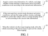
- the method includes: acquiring current state information of the vehicle; judging whether the ramp auxiliary system meets preset activation conditions or not according to the current state information, wherein the preset activation conditions are used for activating the ramp auxiliary system; activating the ramp auxiliary system if the ramp auxiliary system meets the preset activation conditions; judging whether to control the vehicle to be in a torque keeping mode or not according to the current state information, wherein the torque for driving the vehicle is kept unchanged in the torque keeping mode; and when the vehicle is in the torque keeping mode, driving the vehicle according to the preset torque to prevent the vehicle from slipping.
- the control method of the ramp auxiliary system of the vehicle includes: when the ramp auxiliary system meets the preset activation conditions, activating the ramp auxiliary system; judging whether to control the vehicle to be in the torque keeping mode or not according to the current state information of the vehicle; and when the vehicle is in the torque keeping mode, driving the vehicle according to the preset torque to prevent the vehicle from slipping. Therefore, the running state of the vehicle can be accurately and comprehensively judged in advance, and driving control can be automatically performed on the vehicle in time to prevent the vehicle from slipping, thereby improving the safety of the vehicle.
- a second embodiment of this application provides a ramp auxiliary system of a vehicle, wherein the vehicle is driven by a rim motor.
- the system includes an acquisition module which is used for acquiring current state information of the vehicle; a judgment module which is used for judging whether the ramp auxiliary system meets preset activation conditions or not according to the current state information, wherein the preset activation conditions are used for activating the ramp auxiliary system; an activation module which is used for activating the ramp auxiliary system when the ramp auxiliary system meets the preset activation conditions; and a control module which is used for judging whether to control the vehicle to be in a torque keeping mode or not according to the current state information when the ramp auxiliary system is activated, and driving the vehicle according to preset torque when the vehicle is in the torque keeping mode to prevent the vehicle from slipping, wherein the torque for driving the vehicle is kept unchanged in the torque keeping mode.
- the activation module activates the ramp auxiliary system, and the control module judges whether to control the vehicle to be in the torque keeping mode or not according to the current state information of the vehicle; and when the vehicle is in the torque keeping mode, the control module drives the vehicle according to the preset torque to prevent the vehicle from slipping. Therefore, the running state of the vehicle can be accurately and comprehensively judged in advance, and driving control can be automatically performed on the vehicle in time to prevent the vehicle from slipping, thereby improving the safety of the vehicle.
- a third embodiment of this application provides a vehicle, and the vehicle includes the ramp auxiliary system of the vehicle according to the second embodiment of this application.
- the running state of the vehicle according to the embodiment of this application can be accurately and comprehensively judged in advance, and driving control can be automatically performed in time to prevent the vehicle from slipping, thereby improving the safety.
- a fourth embodiment of this application provides a computer storage medium used for storing a computer instruction, wherein when the computer instruction is executed by a controller of equipment, the control method of the ramp auxiliary system of the vehicle is executed.
- Fig. 1 is a flow diagram of a control method of a ramp auxiliary system of a vehicle according to one embodiment of this application.
- the vehicle according to the embodiment of this application may be driven by rim motors, and each wheel of the vehicle may be correspondingly provided with one rim motor.
- a front left wheel 2fl is driven or braked by a rim motor 3fl
- a front right wheel 2fr is driven or braked by a rim motor 3fr
- a rear left wheel 2rl is driven or braked by a rim motor 3rl
- a rear right wheel 2rr is driven or braked by a rim motor 3rr.
- the control method of the ramp auxiliary system of the vehicle includes the followings.
- the preset activation conditions are used for activating the ramp auxiliary system.
- the current state information of the vehicle includes at least one of the current gear of the vehicle, the current vehicle speed of the vehicle, the current slope of the vehicle, accelerator pedal information of the vehicle, brake pedal information of the vehicle, rotation speed information of the rim motors, orientation information of a head of the vehicle and the like.
- the vehicle according to the embodiment of this application also may include wheel speed sensors 1fl, 1fr, 1rl and 1rr which are arranged corresponding to each wheel and are used for respectively acquiring current rotation speeds of the front left wheel 2fl, the front right wheel 2fr, the rear left wheel 2rl and the rear right wheel 2rr. After the current rotation speeds of the wheels are acquired, the current vehicle speed of the vehicle may be further acquired according to the relationship between the rotation speeds of the wheels and the vehicle speed.
- the vehicle also may include an ECU (Electronic Control Unit) and an MCU (Motor Control Unit).
- the MCU may control the magnitude and direction of driving force and brake force of each rim motor, and the MCU also may acquire rotation speed information of each rim motor.
- the MCU may acquire the rotation speed of a single rim motor and also may acquire the rotation speeds of multiple or all of the rim motors.
- the current gear of the vehicle, the current slope of the vehicle, the accelerator pedal information of the vehicle, the brake pedal information of the vehicle and the orientation information of the head of the vehicle may be respectively acquired by the ECU through a gear sensor, a slope sensor, an accelerator pedal sensor, a brake pedal sensor and a gravity sensor.
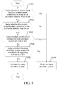
- the ramp auxiliary system may be controlled to be in an activation standby state according to the current gear of the vehicle and the current slope of the vehicle. After the ramp auxiliary system is in the activation standby state, whether the ramp auxiliary system meets the preset conditions (namely conditions of triggering activation) or not may be judged according to the current vehicle speed of the vehicle, the accelerator pedal information of the vehicle and the brake pedal information of the vehicle, and if so, the ramp auxiliary system is judged to meet the preset activation conditions.
- the activation standby state is used for indicating that the ramp auxiliary system is already started and waits for activation.
- the ramp auxiliary system may be controlled to be in the activation standby state.
- the ramp auxiliary system is in the activation standby state, if the current vehicle speed of the vehicle is zero, and when the accelerator pedal of the vehicle is not stepped on and the brake pedal of the vehicle is stepped on, brake force is greater than slip force of the vehicle on a ramp, namely the preset conditions are met, the ramp auxiliary system is judged to meet the preset activation conditions.
- whether to control the vehicle to be in the torque keeping mode or not may be further judged according to the current state information. Specifically, whether the entire driving force of the vehicle is greater than the slip force of the vehicle on the ramp or not may be judged according to the accelerator pedal information of the vehicle, the brake pedal information of the vehicle, the current gear of the vehicle, the rotation speed information of the rim motors and the orientation information of the head of the vehicle.
- the slip force is equal to a downward component force of the self-gravity of the vehicle along the slope minus an upward friction force along the slope; and when the vehicle normally starts, the slip force is equal to the downward component force of the self-gravity of the vehicle along the slope plus a downward friction force along the slope.
- the slip state includes a front slip state due to downhill reversing and a rear slip state due to uphill starting.
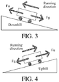
- Fig. 3 shows a stress condition when the vehicle stands on the ramp, the head of the vehicle is downward and the vehicle is ready to reverse.
- the vehicle In a reversing starting process, within a period of time that the brake pedal is loosened and the accelerator pedal is stepped on, the vehicle is subjected to upward driving force Fu parallel to the ramp and slip force Fg, wherein the slip force Fg is a resultant force of the downward component force of the self-gravity of the vehicle along the slope and the friction force of the pavement to the vehicle.
- the entire vehicle is subjected to the resultant force downward along the slope, the vehicle is short of power, and may result in a slipping downward tendency of the vehicle, that is, the vehicle may be in a front slip state due to downhill reversing.
- Fig. 4 shows a stress condition when the vehicle stands on the ramp, the head of the vehicle is upward and the vehicle is ready to start.
- the vehicle In a starting process, within a period of time that the brake pedal is loosened and the accelerator pedal is stepped on, the vehicle is subjected to the upward driving force Fu parallel to the ramp and the slip force Fg, wherein the slip force Fg is the resultant force of the downward component force of the self-gravity of the vehicle along the slope and the friction force of the pavement to the vehicle.
- the entire vehicle is subjected to the resultant force downward along the slope, the vehicle is short of power, and may result in a slipping downward tendency of the vehicle, that is, the vehicle may be in a rear slip state due to uphill starting.
- the preset torque may be calibrated according to the slip force of the vehicle on different ramps. It should be understood that when the vehicle is driven according to the preset torque, the vehicle may be kept to not slide down, namely the vehicle does not slip.
- the ramp auxiliary system when the vehicle is driven according to the preset torque, whether the driving force corresponding to the entire actual output torque of the vehicle is greater than the slip force of the vehicle on the ramp or not is also judged, wherein if the driving force corresponding to the entire actual output torque of the vehicle is greater than the slip force of the vehicle on the ramp, the ramp auxiliary system is closed; if the driving force corresponding to the entire actual output torque of the vehicle is less than or equal to the slip force of the vehicle on the ramp, whether the time that the vehicle is in the torque keeping mode reaches preset time or not is judged; and if the time that the vehicle is in the torque keeping mode reaches the preset time, the ramp auxiliary system is closed.
- the control method of the ramp auxiliary system of the vehicle includes: when the ramp auxiliary system meets the preset activation conditions, activating the ramp auxiliary system; judging whether to control the vehicle to be in the torque keeping mode or not according to the current state information of the vehicle; and when the vehicle is in the torque keeping mode, driving the vehicle according to the preset torque to prevent the vehicle from slipping. Therefore, the running state of the vehicle may be accurately and comprehensively judged in advance, and driving control may be automatically performed on the vehicle in time to prevent the vehicle from slipping, thereby improving the safety of the vehicle.
- judging whether the ramp auxiliary system meets the preset activation conditions or not specifically may specifically include:
- control method of the ramp auxiliary system of the vehicle also may include the following steps:
- this application also provides a ramp auxiliary system of a vehicle.
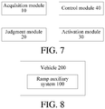
- the ramp auxiliary system of the vehicle includes an acquisition module 10, a judgment module 20, an activation module 30 and a control module 40,
- the acquisition module 10 is used for acquiring current state information of the vehicle; the judgment module 20 is used for judging whether the ramp auxiliary system meets preset activation conditions or not according to the current state information, wherein the preset activation conditions are used for activating the ramp auxiliary system; the activation module 30 is used for activating the ramp auxiliary system when the ramp auxiliary system meets the preset activation conditions; and the control module 40 is used for judging whether to control the vehicle to be in a torque keeping mode or not according to the current state information when the ramp auxiliary system is activated, and driving the vehicle according to preset torque when the vehicle is in the torque keeping mode, to prevent the vehicle from slipping, wherein the torque for driving the vehicle is kept unchanged in the torque keeping mode.
- the current state information of the vehicle includes at least one of the current gear of the vehicle, the current vehicle speed of the vehicle, the current slope of the vehicle, the accelerator pedal information of the vehicle, the brake pedal information of the vehicle, the rotation speed information of the rim motors, the orientation information of the head of the vehicle and the like.
- the vehicle according to the embodiment of this application also may include wheel speed sensors 1fl, 1fr, 1rl and 1rr which are arranged corresponding to each wheel and are used for respectively acquiring current rotation speeds of a front left wheel 2fl, a front right wheel 2fr, a rear left wheel 2rl and a rear right wheel 2rr. After the current rotation speeds of the wheels are acquired, the current vehicle speed of the vehicle may be further acquired according to the relationship between the rotation speeds of the wheels and the vehicle speed.
- wheel speed sensors 1fl, 1fr, 1rl and 1rr which are arranged corresponding to each wheel and are used for respectively acquiring current rotation speeds of a front left wheel 2fl, a front right wheel 2fr, a rear left wheel 2rl and a rear right wheel 2rr.
- the vehicle also may include an ECU and an MCU.
- the MCU may control the magnitude and direction of the driving force and brake force of each rim motor, and the MCU also may acquire the rotation speed information of each rim motor, wherein the MCU may acquire the rotation speed of a single rim motor and also can acquire the rotation speeds of a plurality of rim motors or all rim motors.
- the current gear of the vehicle, the current slope of the vehicle, the accelerator pedal information of the vehicle, the brake pedal information of the vehicle and the orientation information of the head of the vehicle may be respectively acquired by the ECU through a gear sensor, a slope sensor, an accelerator pedal sensor, a brake pedal sensor and a gravity sensor.
- the judgment module 20 may control the ramp auxiliary system to be in an activation standby state according to the current gear of the vehicle and the current slope of the vehicle. After the ramp auxiliary system is in the activation standby state, the judgment module 20 may judge whether the ramp auxiliary system meets the preset conditions (conditions of triggering activation) or not according to the current vehicle speed of the vehicle, the accelerator pedal information of the vehicle and the brake pedal information of the vehicle, and judge that the ramp auxiliary system meets the preset activation conditions when the conditions of triggering activation are met.
- the activation standby state is used for indicating that the ramp auxiliary system is already started and waits for activation.
- the judgment module 20 may control the ramp auxiliary system to be in the activation standby state. After the ramp auxiliary system is in the activation standby state, if the current vehicle speed of the vehicle is zero, and when the accelerator pedal of the vehicle is not stepped on and the brake pedal of the vehicle is stepped on, brake force is greater than the slip force of the vehicle on a ramp, namely the preset conditions are met, the judgment module 20 may judge that the ramp auxiliary system meets the preset activation conditions.
- the control module 40 may further judge whether to control the vehicle to be in a torque keeping mode or not according to the current state information. Specifically, the control module 40 may judge whether the entire driving force of the vehicle is greater than the slip force of the vehicle on the ramp or not according to the accelerator pedal information of the vehicle, the brake pedal information, the current gear of the vehicle, the rotation speed information of the rim motors and the orientation information of the head of the vehicle.
- the slip force is equal to the downward component force of the self-gravity of the vehicle along the slope minus the upward friction force along the slope; when the vehicle normally starts, the slip force is equal to the downward component force of the self-gravity of the vehicle along the slope plus the downward friction force along the slope.
- the control module 40 judges that the vehicle may be in a slip state and controls the vehicle to be in the torque keeping mode, wherein the slip state includes a front slip state due to downhill reversing and a rear slip state due to uphill starting.
- Fig. 3 shows a stress condition when the vehicle stands on the ramp, the head of the vehicle is downward and the vehicle is ready to reverse.
- the vehicle In a reversing starting process, within a period of time that the brake pedal is loosened and the accelerator pedal is stepped on, the vehicle is subjected to upward driving force Fu parallel to the ramp and slip force Fg, wherein the slip force Fg is a resultant force of the downward component force of the self-gravity of the vehicle along the slope and the friction force of the pavement to the vehicle.
- the entire vehicle is subjected to the resultant force downward along the slope, the vehicle is short of power, and may result in a slipping downward tendency of the vehicle, that is, the vehicle may be in a front slip state due to downhill reversing.
- Fig. 4 shows a stress condition when the vehicle stands on the ramp, the head of the vehicle is upward and the vehicle is ready to start.
- the vehicle In a starting process, within a period of time that the brake pedal is loosened and the accelerator pedal is stepped on, the vehicle is subjected to the upward driving force Fu parallel to the ramp and the slip force Fg, wherein the slip force Fg is a resultant force of the downward component force of the self-gravity of the vehicle along the slope and the friction force of the pavement to the vehicle.
- the entire vehicle is subjected to the resultant force downward along the slope, the vehicle is short of power, and may result in a slipping downward tendency of the vehicle, that is, the vehicle may be in a rear slip state due to uphill starting.
- the preset torque value may be calibrated according to the slip force of the vehicle on different ramps. It should be understood that when the vehicle is subjected to driving control according to the preset torque value, the vehicle can be kept to not slide down, namely the vehicle does not slip.
- control module 40 when the control module 40 drives the vehicle according to the preset torque, whether the driving force corresponding to the entire actual output torque of the vehicle is greater than the slip force of the vehicle on the ramp or not is also judged, wherein if the driving force corresponding to the entire actual output torque of the vehicle is greater than the slip force of the vehicle on the ramp, the control module 40 closes the ramp auxiliary system; if the driving force corresponding to the entire actual output torque of the vehicle is less than or equal to the slip force of the vehicle on the ramp, the control module 40 judges whether the time that the vehicle is in the torque keeping mode reaches preset time or not; and if the time that the vehicle is in the torque keeping mode reaches the preset time, the control module closes the ramp auxiliary system.
- the activation module activates the ramp auxiliary system, and the control module judges whether to control the vehicle to be in the torque keeping mode or not according to the current state information of the vehicle; and when the vehicle is in the torque keeping mode, the control module performs driving control according to the preset torque to prevent the vehicle from slipping. Therefore, the running state of the vehicle can be accurately and comprehensively judged in advance, and driving control can be automatically performed on the vehicle in time to prevent the vehicle from slipping, thereby improving the safety of the vehicle.
- this application also provides a vehicle.
- the vehicle 200 includes the ramp auxiliary system 100 provided by the above embodiment of this application, and the specific implementation mode may refer to the above embodiment. In order to avoid redundancy, the descriptions thereof are omitted herein.
- the running state of the vehicle according to the embodiment of this application can be accurately and comprehensively judged in advance, and driving control can be automatically performed on the vehicle in time to prevent the vehicle from slipping, thereby improving the safety of the vehicle.
- this application also provides a computer storage medium used for storing a computer instruction.
- the computer instruction is executed by a controller of equipment, the control method of the ramp auxiliary system of the vehicle is executed.
- orientations or position relationships indicated by terms such as “center”, “longitudinal”, “transverse”, “length”, “width”, “thickness”, “up”, “down”, “front”, “back”, “left”, “right”, “vertical”, “horizontal”, “top”, “bottom”, “inner”, “outer”, “clockwise”, “counterclockwise”, “axial”, “radial”, and “circumferential” are orientations or position relationship shown based on the accompanying drawings, and are merely used for describing this application and simplifying the description, rather than indicating or implying that the apparatus or element should have a particular orientation or be constructed and operated in a particular orientation, and therefore, should not be construed as a limitation on this application.
- first and second are used only for description purposes, and shall not be understood as indicating or suggesting relative importance or implicitly indicating a quantity of indicated technical features. Therefore, features modified by “first “ and “second” may explicitly or implicitly include one or more features. In descriptions of this application, “multiple” means two or more, unless otherwise defined clearly and specifically.
- mount should be understood in a generalized manner, for example, may be understood as fixed connection, detachable connection, or integration; or may be understood as mechanical connection, electrical connection, or mutual communication; or may be understood as direct connection, or indirect connection by means of a medium, or internal communication of two elements or a mutual relationship between two elements.
- fix should be understood in a generalized manner, for example, may be understood as fixed connection, detachable connection, or integration; or may be understood as mechanical connection, electrical connection, or mutual communication; or may be understood as direct connection, or indirect connection by means of a medium, or internal communication of two elements or a mutual relationship between two elements.
Landscapes
- Engineering & Computer Science (AREA)
- Power Engineering (AREA)
- Transportation (AREA)
- Mechanical Engineering (AREA)
- Electric Propulsion And Braking For Vehicles (AREA)
- Hybrid Electric Vehicles (AREA)
- Control Of Transmission Device (AREA)
Applications Claiming Priority (2)
| Application Number | Priority Date | Filing Date | Title |
|---|---|---|---|
| CN201611069046.4A CN108116269B (zh) | 2016-11-28 | 2016-11-28 | 车辆、车辆的坡道辅助系统及其控制方法 |
| PCT/CN2017/110845 WO2018095242A1 (zh) | 2016-11-28 | 2017-11-14 | 车辆、车辆的坡道辅助系统及其控制方法 |
Publications (2)
| Publication Number | Publication Date |
|---|---|
| EP3546274A1 true EP3546274A1 (de) | 2019-10-02 |
| EP3546274A4 EP3546274A4 (de) | 2019-12-11 |
Family
ID=62195745
Family Applications (1)
| Application Number | Title | Priority Date | Filing Date |
|---|---|---|---|
| EP17874203.7A Withdrawn EP3546274A4 (de) | 2016-11-28 | 2017-11-14 | Fahrzeug, steigungsassistenzsystem für fahrzeug und steuerungsverfahren dafür |
Country Status (5)
| Country | Link |
|---|---|
| US (1) | US20200055409A1 (de) |
| EP (1) | EP3546274A4 (de) |
| KR (1) | KR20190059967A (de) |
| CN (1) | CN108116269B (de) |
| WO (1) | WO2018095242A1 (de) |
Cited By (3)
| Publication number | Priority date | Publication date | Assignee | Title |
|---|---|---|---|---|
| CN111231695A (zh) * | 2020-01-17 | 2020-06-05 | 浙江飞碟汽车制造有限公司 | 一种纯电动卡车用驱动电机系统坡道辅助控制方法 |
| CN112622640A (zh) * | 2021-01-05 | 2021-04-09 | 潍柴动力股份有限公司 | 一种坡道驻车方法和车辆 |
| WO2022184398A1 (de) * | 2021-03-05 | 2022-09-09 | Bayerische Motoren Werke Aktiengesellschaft | VERFAHREN UND STEUERVORRICHTUNG ZUM BETRIEB EINES STRAßENGEKOPPELTEN ALLRADFAHRZEUGES |
Families Citing this family (21)
| Publication number | Priority date | Publication date | Assignee | Title |
|---|---|---|---|---|
| CN108725259A (zh) * | 2018-06-26 | 2018-11-02 | 南京恒天领锐汽车有限公司 | 一种新型四驱纯电动客车大坡起步控制系统 |
| CN110303901B (zh) * | 2019-07-12 | 2022-06-14 | 重庆长安新能源汽车科技有限公司 | 一种汽车坡道辅助制动方法、装置及电动汽车 |
| CN110435443B (zh) * | 2019-08-19 | 2021-08-27 | 安徽江淮汽车集团股份有限公司 | 坡道辅助控制方法、装置、设备及存储介质 |
| CN111169441B (zh) * | 2020-01-09 | 2022-03-08 | 宁波吉利汽车研究开发有限公司 | 一种自动驻车控制方法、系统及终端 |
| CN113771639B (zh) * | 2020-06-08 | 2024-01-30 | 北京新能源汽车股份有限公司 | 一种扭矩控制方法、装置及车辆 |
| CN111746303A (zh) * | 2020-07-09 | 2020-10-09 | 长泰鑫顺泰实业发展有限公司 | 电动汽车控制方法 |
| CN111907340A (zh) * | 2020-07-14 | 2020-11-10 | 宝能(广州)汽车研究院有限公司 | 一种用于车辆的制动方法、电机控制器及车辆 |
| CN112009264B (zh) * | 2020-08-13 | 2021-12-28 | 吉利汽车研究院(宁波)有限公司 | 一种防止车辆溜坡的控制方法、设备及车辆 |
| CN112373450B (zh) * | 2020-11-10 | 2022-04-05 | 上海拿森汽车电子有限公司 | 一种车辆辅助转弯的控制方法及装置 |
| CN112428985A (zh) * | 2020-11-19 | 2021-03-02 | 宝能(广州)汽车研究院有限公司 | 下坡辅助控制方法以及采用其的车辆 |
| CN112498126B (zh) * | 2020-12-16 | 2023-01-17 | 芜湖杰诺瑞汽车电器系统有限公司 | 一种汽车电驱系统零转速控制方法 |
| CN112622641B (zh) * | 2021-01-07 | 2022-11-04 | 广西宁达汽车科技有限公司 | 车辆控制方法、装置和系统 |
| CN115071424B (zh) * | 2021-03-01 | 2024-03-19 | 观致汽车有限公司 | 车辆控制方法和车辆 |
| CN112895914B (zh) * | 2021-03-01 | 2024-04-19 | 宜宾丰川动力科技有限公司 | 一种车辆控制方法、装置、及电子设备的控制器 |
| CN113119751B (zh) * | 2021-05-12 | 2022-11-01 | 湖南三一智能控制设备有限公司 | 车辆斜坡启动方法、装置、车辆、电子设备和存储介质 |
| CN113479073B (zh) * | 2021-08-02 | 2024-05-17 | 潍柴动力股份有限公司 | 一种防溜坡控制方法、装置、整车控制器及存储介质 |
| CN113788025B (zh) * | 2021-08-27 | 2023-06-27 | 东风汽车集团股份有限公司 | 一种坡道检测方法、装置及车辆 |
| CN113829898B (zh) * | 2021-11-15 | 2023-09-12 | 合众新能源汽车股份有限公司 | 车辆控制方法和车辆 |
| CN114179621B (zh) * | 2021-12-23 | 2023-04-28 | 奇瑞商用车(安徽)有限公司 | 车辆的陡坡缓降控制方法及装置 |
| CN114475562B (zh) * | 2021-12-28 | 2024-05-28 | 东风汽车集团股份有限公司 | 一种拥堵坡道车辆跟车行驶的制动辅助控制方法和系统 |
| CN114407897A (zh) * | 2022-01-20 | 2022-04-29 | 东风汽车股份有限公司 | 一种车辆坡道辅助功能触发控制方法、记录媒体及系统 |
Family Cites Families (13)
| Publication number | Priority date | Publication date | Assignee | Title |
|---|---|---|---|---|
| CN101209682B (zh) * | 2006-12-26 | 2010-09-29 | 比亚迪股份有限公司 | 电动汽车爬坡状态下电机输出转矩控制系统及控制方法 |
| CN103180519B (zh) * | 2010-10-15 | 2015-04-01 | 日立建机株式会社 | 混合动力工程机械 |
| CN101966822A (zh) * | 2010-10-26 | 2011-02-09 | 上海中科深江电动车辆有限公司 | 纯电动车辆怠速防倒溜控制方法 |
| CN102431530B (zh) * | 2011-10-28 | 2013-12-25 | 吉林大学 | 智能驻车制动及辅助起步控制方法 |
| DE102012223867A1 (de) * | 2012-12-19 | 2014-06-26 | Bayerische Motoren Werke Aktiengesellschaft | Halten eines ein elektrisches Antriebssystem umfassenden Kraftfahrzeugs auf einer geneigten Fläche |
| CN103879306B (zh) * | 2014-04-09 | 2016-06-08 | 奇瑞新能源汽车技术有限公司 | 一种汽车坡道辅助系统及其控制方法 |
| CN103895531B (zh) * | 2014-04-18 | 2016-04-20 | 清华大学苏州汽车研究院(吴江) | 纯电动车坡道起步控制方法 |
| CN104057840A (zh) * | 2014-06-19 | 2014-09-24 | 江铃汽车股份有限公司 | 一种电动汽车坡道驻车起步辅助系统 |
| JP6357045B2 (ja) * | 2014-07-31 | 2018-07-11 | 日立オートモティブシステムズ株式会社 | ブレーキ装置 |
| CN204323098U (zh) * | 2014-11-17 | 2015-05-13 | 万向电动汽车有限公司 | 电动汽车坡道起步辅助系统 |
| CN104590052B (zh) * | 2014-12-31 | 2017-12-19 | 北京新能源汽车股份有限公司 | 一种坡起防溜车控制方法 |
| CN105313861B (zh) * | 2015-11-10 | 2020-08-04 | 中国北方车辆研究所 | 一种载重车辆用坡道起步辅助系统及其控制方法 |
| CN105711590A (zh) * | 2016-05-03 | 2016-06-29 | 重庆长安汽车股份有限公司 | 一种坡道起步辅助控制方法和装置 |
-
2016
- 2016-11-28 CN CN201611069046.4A patent/CN108116269B/zh active Active
-
2017
- 2017-11-14 WO PCT/CN2017/110845 patent/WO2018095242A1/zh active Application Filing
- 2017-11-14 KR KR1020197013157A patent/KR20190059967A/ko active Search and Examination
- 2017-11-14 US US16/461,285 patent/US20200055409A1/en not_active Abandoned
- 2017-11-14 EP EP17874203.7A patent/EP3546274A4/de not_active Withdrawn
Cited By (3)
| Publication number | Priority date | Publication date | Assignee | Title |
|---|---|---|---|---|
| CN111231695A (zh) * | 2020-01-17 | 2020-06-05 | 浙江飞碟汽车制造有限公司 | 一种纯电动卡车用驱动电机系统坡道辅助控制方法 |
| CN112622640A (zh) * | 2021-01-05 | 2021-04-09 | 潍柴动力股份有限公司 | 一种坡道驻车方法和车辆 |
| WO2022184398A1 (de) * | 2021-03-05 | 2022-09-09 | Bayerische Motoren Werke Aktiengesellschaft | VERFAHREN UND STEUERVORRICHTUNG ZUM BETRIEB EINES STRAßENGEKOPPELTEN ALLRADFAHRZEUGES |
Also Published As
| Publication number | Publication date |
|---|---|
| CN108116269B (zh) | 2020-08-07 |
| WO2018095242A1 (zh) | 2018-05-31 |
| EP3546274A4 (de) | 2019-12-11 |
| US20200055409A1 (en) | 2020-02-20 |
| CN108116269A (zh) | 2018-06-05 |
| KR20190059967A (ko) | 2019-05-31 |
Similar Documents
| Publication | Publication Date | Title |
|---|---|---|
| EP3546274A1 (de) | Fahrzeug, steigungsassistenzsystem für fahrzeug und steuerungsverfahren dafür | |
| CN105459847A (zh) | 电动汽车坡道起步辅助系统及其控制方法 | |
| CN104943666B (zh) | 用于车辆的自动驻车控制系统及其控制方法、车辆 | |
| CN204323098U (zh) | 电动汽车坡道起步辅助系统 | |
| CN108162799B (zh) | 一种电动汽车防溜坡的方法 | |
| US8521387B2 (en) | Method for assisting with hill starts | |
| CN106347357A (zh) | 使车辆分离离合器具有预行程的策略 | |
| CN102220914B (zh) | 多阶段发动机停止位置控制 | |
| CN106926745A (zh) | 纯电动汽车起步蠕行及防溜坡策略 | |
| US10259449B2 (en) | Method for operating a drive device and corresponding hybrid drive device | |
| CN111169291B (zh) | 车辆蠕行扭矩的控制方法、装置及车辆 | |
| CN102245424A (zh) | 扭矩控制系统 | |
| CN105799550B (zh) | 纯电动汽车防溜坡控制方法 | |
| CN106553632A (zh) | 一种控制车辆从静止起步的方法 | |
| CN107054369A (zh) | 改进的具有手动换挡变速器的机动车辆的自动启动/停止系统 | |
| CN106828193B (zh) | 一种坡道起步控制方法及电动汽车 | |
| CN112009265A (zh) | 一种纯电商用车蠕行和防溜坡集成控制方法及系统 | |
| CN108327713B (zh) | 汽车及其的车身稳定控制方法、系统 | |
| CN107985312B (zh) | 一种电动车起动方法及电动车 | |
| CN105480297B (zh) | 电动转向装置 | |
| CN107351836A (zh) | 一种四轮电动车的踏板标定方法 | |
| CN112622636B (zh) | 防溜坡控制方法、装置及车辆 | |
| CN113968209B (zh) | 车辆及其控制方法和控制装置 | |
| US20220340013A1 (en) | Vehicle and braking method and device therefor | |
| US20180141539A1 (en) | Shift control method for hybrid electric vehicle |
Legal Events
| Date | Code | Title | Description |
|---|---|---|---|
| STAA | Information on the status of an ep patent application or granted ep patent |
Free format text: STATUS: THE INTERNATIONAL PUBLICATION HAS BEEN MADE |
|
| PUAI | Public reference made under article 153(3) epc to a published international application that has entered the european phase |
Free format text: ORIGINAL CODE: 0009012 |
|
| STAA | Information on the status of an ep patent application or granted ep patent |
Free format text: STATUS: REQUEST FOR EXAMINATION WAS MADE |
|
| 17P | Request for examination filed |
Effective date: 20190607 |
|
| AK | Designated contracting states |
Kind code of ref document: A1 Designated state(s): AL AT BE BG CH CY CZ DE DK EE ES FI FR GB GR HR HU IE IS IT LI LT LU LV MC MK MT NL NO PL PT RO RS SE SI SK SM TR |
|
| AX | Request for extension of the european patent |
Extension state: BA ME |
|
| A4 | Supplementary search report drawn up and despatched |
Effective date: 20191107 |
|
| RIC1 | Information provided on ipc code assigned before grant |
Ipc: B60L 15/20 20060101AFI20191101BHEP |
|
| DAV | Request for validation of the european patent (deleted) | ||
| DAX | Request for extension of the european patent (deleted) | ||
| STAA | Information on the status of an ep patent application or granted ep patent |
Free format text: STATUS: THE APPLICATION HAS BEEN WITHDRAWN |
|
| 18W | Application withdrawn |
Effective date: 20200525 |