EP3538410B1 - Schienenfahrzeug mit innenraumabschnitten auf verschiedenen fussbodenhöhen - Google Patents
Schienenfahrzeug mit innenraumabschnitten auf verschiedenen fussbodenhöhen Download PDFInfo
- Publication number
- EP3538410B1 EP3538410B1 EP18700465.0A EP18700465A EP3538410B1 EP 3538410 B1 EP3538410 B1 EP 3538410B1 EP 18700465 A EP18700465 A EP 18700465A EP 3538410 B1 EP3538410 B1 EP 3538410B1
- Authority
- EP
- European Patent Office
- Prior art keywords
- rail vehicle
- floor
- interior portion
- vehicle according
- lifting
- Prior art date
- Legal status (The legal status is an assumption and is not a legal conclusion. Google has not performed a legal analysis and makes no representation as to the accuracy of the status listed.)
- Active
Links
Images

Classifications
-
- B—PERFORMING OPERATIONS; TRANSPORTING
- B61—RAILWAYS
- B61D—BODY DETAILS OR KINDS OF RAILWAY VEHICLES
- B61D23/00—Construction of steps for railway vehicles
- B61D23/02—Folding steps for railway vehicles, e.g. hand or mechanically actuated
-
- A—HUMAN NECESSITIES
- A61—MEDICAL OR VETERINARY SCIENCE; HYGIENE
- A61G—TRANSPORT, PERSONAL CONVEYANCES, OR ACCOMMODATION SPECIALLY ADAPTED FOR PATIENTS OR DISABLED PERSONS; OPERATING TABLES OR CHAIRS; CHAIRS FOR DENTISTRY; FUNERAL DEVICES
- A61G3/00—Ambulance aspects of vehicles; Vehicles with special provisions for transporting patients or disabled persons, or their personal conveyances, e.g. for facilitating access of, or for loading, wheelchairs
- A61G3/02—Loading or unloading personal conveyances; Facilitating access of patients or disabled persons to, or exit from, vehicles
- A61G3/06—Transfer using ramps, lifts or the like
- A61G3/062—Transfer using ramps, lifts or the like using lifts connected to the vehicle
-
- A—HUMAN NECESSITIES
- A61—MEDICAL OR VETERINARY SCIENCE; HYGIENE
- A61G—TRANSPORT, PERSONAL CONVEYANCES, OR ACCOMMODATION SPECIALLY ADAPTED FOR PATIENTS OR DISABLED PERSONS; OPERATING TABLES OR CHAIRS; CHAIRS FOR DENTISTRY; FUNERAL DEVICES
- A61G3/00—Ambulance aspects of vehicles; Vehicles with special provisions for transporting patients or disabled persons, or their personal conveyances, e.g. for facilitating access of, or for loading, wheelchairs
- A61G3/02—Loading or unloading personal conveyances; Facilitating access of patients or disabled persons to, or exit from, vehicles
- A61G3/06—Transfer using ramps, lifts or the like
- A61G3/068—Transfer using ramps, lifts or the like in combination with folding stairs
-
- B—PERFORMING OPERATIONS; TRANSPORTING
- B61—RAILWAYS
- B61D—BODY DETAILS OR KINDS OF RAILWAY VEHICLES
- B61D1/00—Carriages for ordinary railway passenger traffic
-
- B—PERFORMING OPERATIONS; TRANSPORTING
- B61—RAILWAYS
- B61D—BODY DETAILS OR KINDS OF RAILWAY VEHICLES
- B61D17/00—Construction details of vehicle bodies
- B61D17/04—Construction details of vehicle bodies with bodies of metal; with composite, e.g. metal and wood body structures
- B61D17/10—Floors
-
- A—HUMAN NECESSITIES
- A61—MEDICAL OR VETERINARY SCIENCE; HYGIENE
- A61G—TRANSPORT, PERSONAL CONVEYANCES, OR ACCOMMODATION SPECIALLY ADAPTED FOR PATIENTS OR DISABLED PERSONS; OPERATING TABLES OR CHAIRS; CHAIRS FOR DENTISTRY; FUNERAL DEVICES
- A61G2220/00—Adaptations of particular transporting means
- A61G2220/12—Trains
Definitions
- a rail vehicle is provided with a first interior section with a floor at a first floor level and a second interior section adjoining the first interior section with a floor at a second floor level above the first floor level of the first interior section, a lifting arrangement with a lift platform is provided to overcome the difference between the first and the second floor level, which is dimensioned to accommodate a person with restricted mobility, the lifting arrangement being immediately adjacent to the second interior section in the first Interior section is arranged and the lift platform between a lower position in which its top is flush with a top of the floor in the first interior section, and an upper position in which its top with a top of the floor is aligned in the second interior section, can be moved vertically by means of a drive.
- Such a rail vehicle is from DE 699 27 010 T2 known.
- the technical background of the invention also includes DE 10 2007 018 756 A1 , the subject of which is a lift platform coupled with mobile stairs.
- Such a rail vehicle is, for example, from DE 10 2012 204 304 A1 known.
- the lift platform used there is provided directly in an entry area of the rail vehicle, which in particular also allows people with restricted mobility to enter and exit the rail vehicle. Due to their arrangement in the entry area of the rail vehicle, however, the use of this entry is significantly restricted for other passengers. In the case, for example, when a wheelchair user uses the lift platform as a person with restricted mobility, it is considerably more difficult for other passengers to board.
- the invention is based on the object of further developing a rail vehicle of the type mentioned at the outset in such a way that a general entry of passengers into the rail vehicle is made easier.
- Such a vehicle is characterized in that the lifting arrangement has two staircases, each starting laterally from the lifting platform and coupled to a vertical movement of the lifting platform, which can be retracted and extended in the vertical direction, one of which leads to the floor of the first interior section and the other to the Floor of the second interior section connects.
- the selected position of the lifting arrangement in a transition area between the first and the second interior section means that it is located away from an entrance to the rail vehicle, so that this entrance can be used by passengers without restriction.
- the proposed lifting arrangement allows people with restricted mobility to change between the interior sections with different floor heights.
- the entry and exit of the two provided stairs will be done in opposite directions. When one of the stairs is in its flat position, the other is fully extended and vice versa. It is always guaranteed that the extended stairs can also be used by people who are not restricted in their mobility.
- the lifting arrangement can be arranged in a passage of the first interior section. This offers the advantage that securing the lifting arrangement to the side, i.e. perpendicular to a direction of movement of the passengers, is dispensable.
- the passage can be limited on one side by a side wall lining and on the other side by a built-in module.
- the built-in module can preferably be formed by a sanitary module. In this way, an expedient implementation of the passage results without additional installations having to be made in the rail vehicle.
- Handrails can be provided on the inner side wall cladding, the courses of which are adapted to the positions of the stairs in their retracted and / or extended position. Such handrails facilitate the use of the lifting arrangement for passengers without restricting their mobility.
- an actuating device can be provided to request the lift platform.
- These actuating devices are preferably arranged in such a way that easy access is also provided for wheelchair users standing directly in front of a staircase concerned.
- An actuating device for moving the lifting device from the upper position to the lower position and vice versa can be provided in the area of the lift platform. This enables a user of the lift platform to trigger the desired vertical movement upwards or downwards after taking up the position on the lift platform.
- the first interior section preferably comprises an entry area of the rail vehicle, the height of which is adapted to a predetermined platform height.
- the entry area is suitable for people with restricted mobility to easily get from the platform into the rail vehicle and also to leave it again can.
- the lifting arrangement will be located away from an entry in the first interior section, so that advantageous accessibility of the entry for all persons is achieved.
- the first interior section in particular also the entry area, can be connected via a fixed staircase to a third interior section, which in turn has a floor height that is higher than the first interior section. This floor height can in particular coincide with that of the second interior section.
- the fixed staircase allows people without restricted mobility to use an additional staircase in addition to the staircase of the lifting arrangement in order to get further into the interior of the rail vehicle.
- the two stairs each have at least one step, the vertical movement of which is coupled to the lift platform by means of a guide rod, one end of which is on an associated side of the lift platform and the other end of which is hinged to a floor section immediately adjacent to the stairs.
- a suitable coupling of the vertical movement of the lift platform with the vertical movements of the individual steps of the two stairs is brought about.
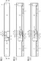
- a passenger compartment is divided in terms of its floor height in the longitudinal direction of a single rail vehicle car as follows: the car is equipped with two end-side bogies 1, 2, a first interior section 3 extends between the bogies 1, 2 and a first floor level having.
- a second interior section 6 extends from an entry door 4 at the end above the first chassis 1 to a lifting arrangement 5.
- the lifting arrangement 5 allows people with restricted mobility to pass from the first interior section 3 to the second interior section 6 opposite the first Interior section 3 of increased floor height.
- a third interior section 7 can be reached from the first interior section 3, to be precise via a staircase 8.
- the third room section 7 is not accessible for people with restricted mobility. It lies above the second chassis 2 and its floor height corresponds to that of the first interior section 6 above the first chassis 1.
- the car In the area of the first interior section 3 with a reduced floor height, the car is equipped with an entrance 9 for people with restricted mobility. Such persons can reach the second interior section 6 using the lifting arrangement 5.
- the lifting arrangement 5 is arranged within the passenger compartment at a distance from the entrance 9, specifically in the first interior section 3 directly adjacent to the second interior section 6.
- An essential element of the lifting arrangement 5 is a lifting platform 10 which can be moved vertically by means of a drive.
- the mobility of the lift platform 10 is between an upper position in which its top is aligned with an upper side of the floor in the second interior section 6 and a lower position in which its upper side is aligned with an upper side of the floor in the first interior section 3 / entry area.
- the lifting arrangement 5 extends in the longitudinal direction of the carriage.
- the lifting arrangement 5 is arranged in a passage of the first interior section 3. This passage is delimited on the one hand by an adjoining interior side wall cladding 11 and on the other by an installation module, in the present case a sanitary module 12.
- the lifting arrangement 5 comprises, in addition to the lifting platform 10 in the longitudinal direction of the carriage, in each case laterally of the lifting platform 5, stairs 13, 14 which can be retracted and extended in the vertical direction and which in the present exemplary embodiment each comprise two steps.
- the stairs 13, 14 are coupled to a vertical movement of the lift platform 5, as will be explained in more detail later.
- the stairs 13 adjoin the floor of the first interior section 3, while the stairs 14 are used to connect the lift platform 10 to the second interior section 6.
- the lifting arrangement When not in use by people with reduced mobility, the lifting arrangement can be used like a conventional staircase, both in its upper and in its lower position.
- two handrails 15 are provided on the side wall inner cladding 11, each of which is assigned to one of the stairs 13, 14 and which interact with a horizontal railing of the lift platform 10.
- actuating device 16 for requesting the lifting platform 10 intended.
- the lifting platform 10 itself is equipped with an actuating device 17 for triggering a movement of the lifting arrangement 5 from the upper position into the lower position and vice versa.
- This actuating device 17 can be actuated by persons located on the lift platform 10.
- the lifting platform 10 also assumes its upper position while the stairs 13 are extended and the stairs 14 are retracted.
- the lifting arrangement 5 takes in Figure 3 its lower position, in which the lift platform 10 connects via the retracted steps of the stairs 13 to the floor of the first interior section 5, while the steps of the stairs 14 are extended.
- both the lifting arrangement 5 and the adjacent section of the side wall inner lining 11 are each provided with an emergency call device 18.
- Figure 4 shows the stairs 13 in a retracted, an intermediate and an extended position, in which the lift platform 10 assumes its upper position.
- an analogue guide for the steps thereof is to be provided.
- Steps 18, 19 of the stairs 13 are guided over suitably designed, vertically extending rails 20.
- the vertical movement of the steps 18, 19 is coupled to the driven lift platform 10 by means of a guide rod 21.
- the guide rod 21 is articulated both on the lifting platform 10 and in the area of the floor of the first interior section 5.
- the steps 18, 19 are individually by means of laterally protruding pins Out of elongated holes which run in the longitudinal direction of the guide rod 21.
Landscapes
- Engineering & Computer Science (AREA)
- Health & Medical Sciences (AREA)
- Public Health (AREA)
- Life Sciences & Earth Sciences (AREA)
- Mechanical Engineering (AREA)
- Animal Behavior & Ethology (AREA)
- General Health & Medical Sciences (AREA)
- Veterinary Medicine (AREA)
- Wood Science & Technology (AREA)
- Transportation (AREA)
- Vehicle Step Arrangements And Article Storage (AREA)
Description
- Die Erfindung bezieht sich auf ein Schienenfahrzeug nach dem Oberbegriff von Anspruch 1. Danach ist vorgesehen ein Schienenfahrzeug mit einem ersten Innenraumabschnitt mit einem Fußboden auf einer ersten Fußbodenhöhe und einem an den ersten Innenraumabschnitt angrenzenden zweiten Innenraumabschnitt mit einem Fußboden auf einer zweiten Fußbodenhöhe, die oberhalb der ersten Fußbodenhöhe des ersten Innenraumabschnitts liegt, wobei zur Überwindung der Differenz zwischen der ersten und der zweiten Fußbodenhöhe eine Hubanordnung mit einer Hubliftplattform vorgesehen ist, die zur Aufnahme einer in ihrer Mobilität eingeschränkten Person bemessen ist, wobei die Hubanordnung dem zweiten Innenraumabschnitt unmittelbar benachbart in dem ersten Innenraumabschnitt angeordnet ist und die Hubliftplattform zwischen einer unteren Position, bei der ihre Oberseite mit einer Oberseite des Fußbodens im ersten Innenraumabschnitt fluchtet, und einer oberen Position, bei der ihre Oberseite mit einer Oberseite des Fußbodens im zweiten Innenraumabschnitt fluchtet, mittels eines Antriebs vertikal verfahrbar ist.
Ein solches Schienenfahrzeug ist aus derDE 699 27 010 T2 bekannt. Zum technischen Hintergrund der Erfindung zählt noch dieDE 10 2007 018 756 A1 , die eine mit fahrbaren Treppen gekoppelte Hubliftplattform zum Gegenstand hat.
Ein solches Schienenfahrzeug ist beispielsweise aus derDE 10 2012 204 304 A1 bekannt. Die dort eingesetzte Hubliftplattform ist unmittelbar in einem Einstiegsbereich des Schienenfahrzeugs vorgesehen, der insbesondere auch ein Betreten und Verlassen des Schienenfahrzeugs durch in ihrer Mobilität eingeschränkten Personen gestattet. Durch ihre Anordnung im Einstiegsbereich des Schienenfahrzeugs wird die Nutzung dieses Einstiegs jedoch für andere Fahrgäste wesentlich eingeschränkt. In dem Fall, wenn beispielsweise ein Rollstuhlfahrer als in ihrer Mobilität eingeschränkte Person die Hubliftplattform benutzt, ist ein Einstieg anderer Fahrgäste erheblich erschwert. - Ausgehend hiervon liegt der Erfindung die Aufgabe zu Grunde, ein Schienenfahrzeug der eingangs genannten Art derart weiter zu entwickeln, dass ein allgemeiner Einstieg von Fahrgästen in das Schienenfahrzeug erleichtert wird.
- Diese Aufgabe wird durch ein Schienenfahrzeug mit den Merkmalen des Anspruchs 1 gelöst.
- Ein solches Fahrzeug zeichnet sich dadurch aus, dass die Hubanordnung zwei jeweils seitlich von der Hubliftplattform ausgehende, gekoppelt an eine Vertikalbewegung der Hubliftplattform in vertikaler Richtung ein- und ausfahrbare Treppen aufweist, von denen die eine an den Fußboden des ersten Innenraumabschnitts und die andere an den Fußboden des zweiten Innenraumabschnitts anschließt.
- Durch die gewählte Position der Hubanordnung in einem Übergangsbereich zwischen dem ersten und dem zweiten Innenraumabschnitt ergibt es sich, dass sie entfernt von einem Einstieg des Schienenfahrzeugs liegt, so dass dieser Einstieg für Fahrgäste uneingeschränkt benutzbar ist. Die vorgesehene Hubanordnung gestattet es jedoch für in ihrer Mobilität eingeschränkte Personen, einen Wechsel zwischen den Innenraumabschnitten mit unterschiedlicher Fußbodenhöhe vorzunehmen. Dabei wird das Ein- und Ausfahren der beiden vorgesehenen Treppen gegenläufig erfolgen. Wenn die eine der Treppen ihre flache Position einnimmt, ist die andere vollständig ausgefahren und umgekehrt. Dabei ist immer gewährleistet, dass die ausgefahrenen Treppen ggf. auch von nicht in ihrer Mobilität eingeschränkten Personen benutzt werden können.
- Die Hubanordnung kann in einem Durchgang des ersten Innenraumabschnitts angeordnet sein. Dies bietet den Vorteil, dass eine Absicherung der Hubanordnung zur Seite, d.h. senkrecht zu einer Bewegungsrichtung der Fahrgäste, entbehrlich ist.
- Dabei kann der Durchgang zur einen Seite durch eine Seitenwandinnenverkleidung und zur anderen Seite durch ein Einbaumodul begrenzt sein. Das Einbaumodul kann bevorzugt von einem Sanitärmodul gebildet sein. In dieser Weise ergibt sich eine zweckdienliche Realisierung des Durchgangs, ohne dass zusätzliche Einbauten in dem Schienenfahrzeug vorzunehmen sind.
- An der Seitenwandinnenverkleidung können Handläufe vorgesehen sein, deren Verläufe an die Lagen der Treppen in deren ein- und/oder ausgefahrenen Position angepasst sind. Solche Handläufe erleichtern die Benutzung der Hubanordnung für Fahrgäste ohne Einschränkung bei ihrer Mobilität.
- Im Bereich der Treppen kann jeweils eine Betätigungsvorrichtung zur Anforderung der Hubliftplattform vorgesehen sein. Diese Betätigungsvorrichtungen werden bevorzugt derart angeordnet sein, dass eine einfache Zugänglichkeit auch für unmittelbar vor einer betreffenden Treppe stehende Rollstuhlfahrer gegeben ist.
- Im Bereich der Hubliftplattform kann eine Betätigungsvorrichtung zur Bewegung der Hubvorrichtung von der oberen Position in die untere und umgekehrt vorgesehen sein. Dies ermöglicht es einem Benutzer der Hubliftplattform, nach Einnahme der Position auf der Hubliftplattform die gewünschte Vertikalbewegung nach oben oder nach unten auszulösen.
- Bevorzugt umfasst der erste Innenraumabschnitt einen Einstiegsbereich des Schienenfahrzeugs, der in seiner Höhe an eine vorgegebene Bahnsteighöhe angepasst ist. Insofern ist der Einstiegsbereich geeignet, dass Personen mit eingeschränkter Mobilität ohne Weiteres vom Bahnsteig in das Schienenfahrzeug gelangen und dieses auch wieder verlassen können. Die Hubanordnung wird auch in diesem Fall entfernt von einem Einstieg im ersten Innenraumabschnitt liegen, so dass eine vorteilhafte Zugänglichkeit des Einstiegs für sämtliche Personen erreicht wird.
- Der erste Innenraumabschnitt, insbesondere auch der Einstiegsbereich, kann über eine feste Treppe mit einem dritten Innenraumabschnitt verbunden sein, der wiederum eine gegenüber dem ersten Innenraumabschnitt erhöhte Fußbodenhöhe aufweist. Diese Fußbodenhöhe kann insbesondere mit derjenigen des zweiten Innenraumabschnitts übereinstimmen. Die feste Treppe gestattet es, dass Personen ohne eingeschränkte Mobilität neben der Treppe der Hubanordnung noch eine zusätzliche Treppe nutzten können, um weiter in den Innenraum des Schienenfahrzeugs zu gelangen.
- Zur Realisierung der Vertikalbewegung der Treppen, insbesondere deren Einfahren und Ausfahren, ist es bevorzugt, dass die beiden Treppen jeweils wenigstens eine Treppenstufe aufweisen, die in ihrer Vertikalbewegung an die Hubliftplattform mittels einer Führungsstange gekoppelt ist, deren eines Ende an einer zugeordneten Seite der Hubliftplattform und deren anderes Ende an einen an die Treppe unmittelbar angrenzenden Fußbodenabschnitt angelenkt ist. In dieser Weise wird eine geeignete Kopplung der Vertikalbewegung der Hubliftplattform mit den Vertikalbewegungen der einzelnen Treppenstufen der beiden Treppen herbeigeführt.
- Ein Ausführungsbeispiel der Erfindung wird nachfolgend anhand der Zeichnungen noch näher erläutert. Es zeigen:
- Figur 1
- eine schematische Ansicht von oben auf einen Innenraumbereich eines Schienenfahrzeugs, ausgestattet mit einer Hubliftplattform,
- Figur 2
- eine schematische Schnittansicht entlang einer Ebene II - II des Innenraumbereichs von
Figur 1 mit der Hubliftplattform in einer oberen Position, - Figur 3
- eine schematische Schnittansicht entlang einer Ebene II - II des Innenraumbereichs von
Figur 1 mit der Hubliftplattform in einer unteren Position und - Figur 4
- eine schematische Seitenansicht der Hubliftplattform in Kombination mit einer ein- und ausfahrbaren Treppe.
- Wie in den
Figuren 1 bis 3 veranschaulicht ist, ist ein Fahrgastinnenraum hinsichtlich seiner Fußbodenhöhe in Längsrichtung eines einzelnen Schienenfahrzeug-Wagens wie folgt aufgeteilt: der Wagen ist mit zwei jeweils endseitigen Fahrwerken 1, 2 ausgestattet, wobei sich ein erster Innenraumabschnitt 3 zwischen den Fahrwerken 1, 2 erstreckt und eine erste Fußbodenhöhe aufweist. Von einer endseitigen Einstiegstür 4 aus oberhalb des ersten Fahrwerks 1 bis hin zu einer Hubanordnung 5 erstreckt sich ein zweiter Innenraumabschnitt 6. Die Hubanordnung 5 gestattet einen Übertritt für in ihrer Mobilität eingeschränkte Personen von dem ersten Innenraumabschnitt 3 zu dem zweiten Innenraumabschnitt 6 mit gegenüber dem ersten Innenraumabschnitt 3 erhöhter Fußbodenhöhe. Weiter lässt sich von dem ersten Innenraumabschnitt 3 aus ein dritter Innenraumabschnitt 7 erreichen, und zwar über eine Treppe 8. Der dritte Raumabschnitt 7 ist für Personen mit eingeschränkter Mobilität nicht zugänglich. Er liegt oberhalb des zweiten Fahrwerks 2 und seine Fußbodenhöhe entspricht derjenigen des ersten Innenraumabschnitts 6 oberhalb des ersten Fahrwerks 1. - Im Bereich des ersten Innenraumabschnitts 3 mit verminderter Fußbodenhöhe ist der Wagen mit einem Einstieg 9 für in ihrer Mobilität eingeschränkte Personen ausgestattet. Solche Personen können den zweiten Innenraumabschnitt 6 unter Benutzung der Hubanordnung 5 erreichen. Dabei ist die Hubanordnung 5 innerhalb des Fahrgastinnenraums von dem Einstieg 9 entfernt angeordnet, und zwar in dem ersten Innenraumabschnitt 3 unmittelbar benachbart dem zweiten Innenraumabschnitt 6.
- Wesentliches Element der Hubanordnung 5 ist eine Hubliftplattform 10, die mittels eines Antriebs vertikal verfahrbar ist. Die Verfahrbarkeit der Hubliftplattform 10 ist zwischen einer oberen Position, bei der ihre Oberseite mit einer Oberseite des Fußbodens im zweiten Innenraumabschnitt 6 fluchtet und einer unteren Position, bei der ihre Oberseite mit einer Oberseite des Fußbodens im ersten Innenraumabschnitt 3/Einstiegsbereich fluchtet, gegeben.
- Wie insbesondere
Figur 1 entnehmbar ist, verläuft die Hubanordnung 5 in Längsrichtung des Wagens. Im Einzelnen ist die Hubanordnung 5 in einem Durchgang des ersten Innenraumabschnitts 3 angeordnet. Dieser Durchgang ist zur einen Seite durch eine angrenzende Seitenwandinnenverkleidung 11 und zur anderen Seite durch ein Einbaumodul begrenzt, im vorliegenden Fall ein Sanitärmodul 12. - Die Hubanordnung 5 umfasst neben der Hubliftplattform 10 in Längsrichtung des Wagens jeweils seitlich von der Hubliftplattform 5 ausgehende, in vertikaler Richtung ein- und ausfahrbare Treppen 13, 14, die im vorliegenden Ausführungsbeispiel jeweils zwei Stufen umfassen. Die Treppen 13, 14 sind an eine Vertikalbewegung der Hubliftplattform 5 gekoppelt, wie später näher erläutert wird. Die Treppe 13 schließt an den Fußboden des ersten Innenraumabschnitts 3 an, während die Treppe 14 zum Anschluss der Hubliftplattform 10 an den zweiten Innenraumabschnitt 6 dient.
- Die Hubanordnung ist bei Nichtbenutzung durch Personen mit eingeschränkter Mobilität wie eine übliche Treppe benutzbar, und zwar sowohl in ihrer oberen als auch in ihrer unteren Position. Dazu sind an der Seitenwandinnenverkleidung 11 zwei Handläufe 15 vorgesehen, deren jeder einer der Treppen 13, 14 zugeordnet ist und die mit einem horizontalen Geländer der Hubliftplattform 10 zusammen wirken.
- Zudem ist im Bereich der Treppen 13, 14 jeweils eine Betätigungsvorrichtung 16 zur Anforderung der Hubliftplattform 10 vorgesehen. Außerdem ist die Hubliftplattform 10 selbst mit einer Betätigungsvorrichtung 17 zum Auslösen einer Bewegung der Hubanordnung 5 von der oberen Position in die untere und umgekehrt ausgestattet. Diese Betätigungsvorrichtung 17 kann von auf der Hubliftplattform 10 befindlichen Personen betätigt werden.
- Es ist ersichtlich, dass bei der in
Figur 2 veranschaulichten oberen Position der Hubanordnung 5 die Hubliftplattform 10 ebenfalls ihre obere Position einnimmt, während die Treppe 13 ausgefahren und die Treppe 14 eingefahren ist. Demgegenüber nimmt die Hubanordnung 5 inFigur 3 ihre untere Position ein, bei der die Hubliftplattform 10 über die eingefahrenen Stufen der Treppe 13 an den Fußboden des ersten Innenraumabschnitts 5 anschließt, während die Stufen der Treppe 14 ausgefahren sind. - Ergänzend ist sowohl die Hubanordnung 5 als auch der benachbarte Abschnitt der Seitenwandinnenverkleidung 11 jeweils mit einer Notrufeinrichtung 18 versehen.
- Aus
Figur 4 geht nunmehr im Detail hervor, wie die Stufen der Treppe 13 einer Vertikalbewegung der Hubliftplattform 10 folgen.Figur 4 zeigt die Treppe 13 in einer eingefahrenen, einer zwischenliegenden und einer ausgefahrenen Position, bei der die Hubliftplattform 10 ihre obere Position einnimmt. Für die der Treppe 13 gegenüberliegende Treppe 14 ist eine analoge Führung für deren Treppenstufen vorzusehen. - Treppenstufen 18, 19 der Treppe 13 sind über geeignet ausgeführte, vertikal verlaufende Schienen 20 geführt. Zudem sind die Treppenstufen 18, 19 in ihrer Vertikalbewegung an die angetriebene Hubliftplattform 10 mittels einer Führungsstange 21 gekoppelt. Die Führungsstange 21 ist sowohl an der Hubliftplattform 10 als auch im Bereich des Fußbodens des ersten Innenraumabschnitts 5 angelenkt. Die Treppenstufen 18, 19 sind einzeln über seitlich herausstehende Stifte mittels Langlöchern geführt, die in Längsrichtung der Führungsstange 21 verlaufen.
Claims (10)
- Schienenfahrzeug mit einem ersten Innenraumabschnitt (3) mit einem Fußboden auf einer ersten Fußbodenhöhe und einem an den ersten Innenraumabschnitt (3) angrenzenden zweiten Innenraumabschnitt (6) mit einem Fußboden auf einer zweiten Fußbodenhöhe, die oberhalb der ersten Fußbodenhöhe des ersten Innenraumabschnitts (3) liegt, wobei zur Überwindung der Differenz zwischen der ersten und der zweiten Fußbodenhöhe eine Hubanordnung (5) mit einer Hubliftplattform (10) vorgesehen ist, die zur Aufnahme einer in ihrer Mobilität eingeschränkten Person bemessen ist, wobei die Hubanordnung (5) dem zweiten Innenraumabschnitt (6) unmittelbar benachbart in dem ersten Innenraumabschnitt (3) angeordnet ist und die Hubliftplattform (10) zwischen einer unteren Position, bei der ihre Oberseite mit einer Oberseite des Fußbodens im ersten Innenraumabschnitt (3) fluchtet, und einer oberen Position, bei der ihre Oberseite mit einer Oberseite des Fußbodens im zweiten Innenraumabschnitt (6) fluchtet, mittels eines Antriebs vertikal verfahrbar ist,
dadurch gekennzeichnet, dass
die Hubanordnung (5) zwei jeweils seitlich von der Hubliftplattform (10) ausgehende, gekoppelt an eine Vertikalbewegung der Hubliftplattform (10) in vertikaler Richtung ein- und ausfahrbare Treppen (13; 14) aufweist, von denen die eine an den Fußboden des ersten Innenraumabschnitts (3) und die andere an den Fußboden des zweiten Innenraumabschnitts (6) anschließt. - Schienenfahrzeug nach Anspruch 1,
dadurch gekennzeichnet, dass
die Hubanordnung (5) in einem Durchgang des ersten Innenraumabschnitts (3) angeordnet ist. - Schienenfahrzeug nach Anspruch 2,
dadurch gekennzeichnet, dass
der Durchgang zur einen Seite durch eine Seitenwandinnenverkleidung (11) und zur anderen Seite durch ein Einbaumodul begrenzt ist. - Schienenfahrzeug nach Anspruch 3,
dadurch gekennzeichnet, dass
das Einbaumodul von einem Sanitärmodul (12) gebildet ist. - Schienenfahrzeug nach einem der Ansprüche 3 oder 4,
dadurch gekennzeichnet, dass
an der Seitenwandinnenverkleidung (11) Handläufe vorgesehen sind, deren Verläufe an die Lagen der Treppen (13; 14) in deren ein- und/oder ausgefahrenen Positionen angepasst sind. - Schienenfahrzeug nach einem der Ansprüche 1 bis 5,
dadurch gekennzeichnet, dass
im Bereich der Treppen (13; 14) jeweils eine Betätigungsvorrichtung (16) zur Anforderung der Hubliftplattform (10) vorgesehen ist. - Schienenfahrzeug nach einem der Ansprüche 1 bis 6,
dadurch gekennzeichnet, dass
im Bereich der Hubliftplattform (10) eine Betätigungsvorrichtung (17) zur Bewegung der Hubanordnung (5) von der oberen Position in die untere oder umgekehrt vorgesehen ist. - Schienenfahrzeug nach einem der Ansprüche 1 bis 7,
dadurch gekennzeichnet, dass
der erste Innenraumabschnitt (3) von einem Einstiegsbereich des Schienenfahrzeugs gebildet ist, der in seiner Höhe an eine vorgegebene Bahnsteighöhe angepasst ist. - Schienenfahrzeug nach Anspruch 8,
dadurch gekennzeichnet, dass
der erste Innenraumabschnitt (3) über eine feste Treppe (8) mit einem dritten Innenraumabschnitt (7) verbunden ist. - Schienenfahrzeug nach einem der Ansprüche 1 bis 9,
dadurch gekennzeichnet, dass
die beiden Treppen (13; 14) jeweils wenigstens eine Treppenstufe (18; 19) aufweisen, die in ihrer Vertikalbewegung an die Hubliftplattform (10) mittels einer Führungsstange (21) gekoppelt ist, deren eines Ende an einer zugeordneten Seite der Hubliftplattform (10) und deren anderes Ende an einen an die Treppe (13; 14) unmittelbar angrenzenden Fußbodenabschnitt angelenkt ist.
Priority Applications (1)
| Application Number | Priority Date | Filing Date | Title |
|---|---|---|---|
| PL18700465T PL3538410T3 (pl) | 2017-01-30 | 2018-01-04 | Pojazd szynowy z odcinkami przestrzeni wewnętrznej na różnych wysokościach podłogi |
Applications Claiming Priority (2)
| Application Number | Priority Date | Filing Date | Title |
|---|---|---|---|
| DE102017201445.8A DE102017201445A1 (de) | 2017-01-30 | 2017-01-30 | Schienenfahrzeug mit Innenraumabschnitten auf verschiedenen Fußbodenhöhen |
| PCT/EP2018/050205 WO2018137910A1 (de) | 2017-01-30 | 2018-01-04 | SCHIENENFAHRZEUG MIT INNENRAUMABSCHNITTEN AUF VERSCHIEDENEN FUßBODENHÖHEN |
Publications (2)
| Publication Number | Publication Date |
|---|---|
| EP3538410A1 EP3538410A1 (de) | 2019-09-18 |
| EP3538410B1 true EP3538410B1 (de) | 2020-12-02 |
Family
ID=60990795
Family Applications (1)
| Application Number | Title | Priority Date | Filing Date |
|---|---|---|---|
| EP18700465.0A Active EP3538410B1 (de) | 2017-01-30 | 2018-01-04 | Schienenfahrzeug mit innenraumabschnitten auf verschiedenen fussbodenhöhen |
Country Status (9)
| Country | Link |
|---|---|
| EP (1) | EP3538410B1 (de) |
| CN (1) | CN211809604U (de) |
| DE (1) | DE102017201445A1 (de) |
| DK (1) | DK3538410T3 (de) |
| ES (1) | ES2858429T3 (de) |
| PL (1) | PL3538410T3 (de) |
| PT (1) | PT3538410T (de) |
| RU (1) | RU194958U1 (de) |
| WO (1) | WO2018137910A1 (de) |
Families Citing this family (5)
| Publication number | Priority date | Publication date | Assignee | Title |
|---|---|---|---|---|
| DE102018123200A1 (de) * | 2018-09-20 | 2020-03-26 | Bombardier Transportation Gmbh | Vorrichtung und Verfahren zum Überwinden einer Höhendifferenz und Schienenfahrzeug mit der Vorrichtung |
| PL4417482T3 (pl) * | 2023-02-17 | 2025-10-13 | Speedinnov | Wagon pojazdu z urządzeniem podnoszącym i odnośny sposób |
| DE102024202761A1 (de) | 2024-03-22 | 2025-09-25 | Siemens Mobility GmbH | Wagenkasten und Schienenfahrzeug |
| DE102024207273A1 (de) | 2024-07-31 | 2026-02-05 | Siemens Mobility GmbH | Hubliftvorrichtung zur Überbrückung unterschiedlicher Fußbodenniveaus in einem Durchgang eines Schienenfahrzeugs |
| DE102024207274A1 (de) * | 2024-07-31 | 2026-02-05 | Siemens Mobility GmbH | Beidseitig nutzbare Klapptreppe für ein Schienenfahrzeug |
Citations (11)
| Publication number | Priority date | Publication date | Assignee | Title |
|---|---|---|---|---|
| EP0307343A1 (de) | 1987-09-08 | 1989-03-15 | Linke-Hofmann-Busch Waggon-Fahrzeug- Maschinen GmbH | Gelenktriebwagen für den Nahverkehr |
| EP1203707A2 (de) | 2000-11-06 | 2002-05-08 | " VEVEY" Technologies S.A. Villeneuve | Verfahren zur Umwandlung von Schienenfahrzeugen und mit diesem Verfahren erhaltene Schienenfahrzeuge |
| EP1464558A2 (de) | 2003-04-04 | 2004-10-06 | Leipziger Fahrzeugservice-Betriebe GmbH LFB | Verfahren zum Einbau eines niederflurigen Mittelteiles in den Wagenkasten eines hochflurigen Schienenfahrzeuges |
| DE69927010T2 (de) | 1998-03-26 | 2006-06-22 | Bombardier Transportation Gmbh | Hebevorrichtung für eisenbahnfahrzeuge |
| DE102007018756A1 (de) | 2007-04-20 | 2008-10-23 | Gunter Reinhold | Hubtreppe |
| EP2060470A2 (de) | 2007-11-19 | 2009-05-20 | Bombardier Transportation GmbH | Doppelstock-Schienenfahrzeug |
| DE102010005298A1 (de) | 2010-01-21 | 2011-07-28 | Reinhold, Gunter, Dipl.-Ing., 80339 | Hubtreppe |
| DE102011118951A1 (de) | 2011-11-21 | 2013-05-23 | DB Systemtechnik GmbH | Anordnung zum Betrieb eines Mehrkomponentenantriebs eines Schienenfahrzeuges |
| DE102012204304A1 (de) | 2012-03-19 | 2013-09-19 | Siemens Aktiengesellschaft | Schienenfahrzeug mit einem für Personen mit reduzierter Mobilität ausgelegten Personeneinstieg |
| DE202014000010U1 (de) | 2014-01-03 | 2014-02-10 | ŠKODA VAGONKA a.s. | Doppelstockreisezugwagen |
| EP2778009A1 (de) | 2013-03-12 | 2014-09-17 | ALSTOM Transport Technologies | Schienenfahrzeug mit einer Vorrichtung zum Einsteigen |
Family Cites Families (2)
| Publication number | Priority date | Publication date | Assignee | Title |
|---|---|---|---|---|
| RU123743U1 (ru) * | 2012-03-26 | 2013-01-10 | Открытое акционерное общество "Тверской вагоностроительный завод" (ОАО "ТВЗ") | Состав двухэтажного пассажирского электропоезда |
| US9095482B2 (en) * | 2013-03-20 | 2015-08-04 | Randall A. Gressett | Lift system |
-
2017
- 2017-01-30 DE DE102017201445.8A patent/DE102017201445A1/de not_active Withdrawn
-
2018
- 2018-01-04 RU RU2019122567U patent/RU194958U1/ru active
- 2018-01-04 DK DK18700465.0T patent/DK3538410T3/da active
- 2018-01-04 CN CN201890000479.0U patent/CN211809604U/zh active Active
- 2018-01-04 EP EP18700465.0A patent/EP3538410B1/de active Active
- 2018-01-04 PT PT187004650T patent/PT3538410T/pt unknown
- 2018-01-04 ES ES18700465T patent/ES2858429T3/es active Active
- 2018-01-04 PL PL18700465T patent/PL3538410T3/pl unknown
- 2018-01-04 WO PCT/EP2018/050205 patent/WO2018137910A1/de not_active Ceased
Patent Citations (11)
| Publication number | Priority date | Publication date | Assignee | Title |
|---|---|---|---|---|
| EP0307343A1 (de) | 1987-09-08 | 1989-03-15 | Linke-Hofmann-Busch Waggon-Fahrzeug- Maschinen GmbH | Gelenktriebwagen für den Nahverkehr |
| DE69927010T2 (de) | 1998-03-26 | 2006-06-22 | Bombardier Transportation Gmbh | Hebevorrichtung für eisenbahnfahrzeuge |
| EP1203707A2 (de) | 2000-11-06 | 2002-05-08 | " VEVEY" Technologies S.A. Villeneuve | Verfahren zur Umwandlung von Schienenfahrzeugen und mit diesem Verfahren erhaltene Schienenfahrzeuge |
| EP1464558A2 (de) | 2003-04-04 | 2004-10-06 | Leipziger Fahrzeugservice-Betriebe GmbH LFB | Verfahren zum Einbau eines niederflurigen Mittelteiles in den Wagenkasten eines hochflurigen Schienenfahrzeuges |
| DE102007018756A1 (de) | 2007-04-20 | 2008-10-23 | Gunter Reinhold | Hubtreppe |
| EP2060470A2 (de) | 2007-11-19 | 2009-05-20 | Bombardier Transportation GmbH | Doppelstock-Schienenfahrzeug |
| DE102010005298A1 (de) | 2010-01-21 | 2011-07-28 | Reinhold, Gunter, Dipl.-Ing., 80339 | Hubtreppe |
| DE102011118951A1 (de) | 2011-11-21 | 2013-05-23 | DB Systemtechnik GmbH | Anordnung zum Betrieb eines Mehrkomponentenantriebs eines Schienenfahrzeuges |
| DE102012204304A1 (de) | 2012-03-19 | 2013-09-19 | Siemens Aktiengesellschaft | Schienenfahrzeug mit einem für Personen mit reduzierter Mobilität ausgelegten Personeneinstieg |
| EP2778009A1 (de) | 2013-03-12 | 2014-09-17 | ALSTOM Transport Technologies | Schienenfahrzeug mit einer Vorrichtung zum Einsteigen |
| DE202014000010U1 (de) | 2014-01-03 | 2014-02-10 | ŠKODA VAGONKA a.s. | Doppelstockreisezugwagen |
Non-Patent Citations (1)
| Title |
|---|
| ANDREW NASH, IMPROVING PASSENGER RAIL ACCESSIBILITY, 4 February 2015 (2015-02-04), XP055840128 |
Also Published As
| Publication number | Publication date |
|---|---|
| DK3538410T3 (da) | 2021-01-25 |
| RU194958U1 (ru) | 2020-01-09 |
| EP3538410A1 (de) | 2019-09-18 |
| ES2858429T3 (es) | 2021-09-30 |
| PT3538410T (pt) | 2021-01-19 |
| WO2018137910A1 (de) | 2018-08-02 |
| DE102017201445A1 (de) | 2018-08-02 |
| PL3538410T3 (pl) | 2021-05-04 |
| CN211809604U (zh) | 2020-10-30 |
Similar Documents
| Publication | Publication Date | Title |
|---|---|---|
| EP3538410B1 (de) | Schienenfahrzeug mit innenraumabschnitten auf verschiedenen fussbodenhöhen | |
| DE69938524T2 (de) | Aufzug mit verstellbaren Geländernoberseiten | |
| EP2641805B1 (de) | Schienenfahrzeug mit einem für Personen mit reduzierter Mobilität ausgelegten Personeneinstieg | |
| EP3541734B2 (de) | Aufzugskabine | |
| DE19911879C1 (de) | Fluggastbrückenkabine | |
| AT513614B1 (de) | Leitersatz, insbesondere Feuerwehrleiter, sowie damit ausgestattetes Fahrzeug | |
| DE102007022387B4 (de) | Ein- und Ausstiegshilfe für Fahrzeuge des Personenverkehrs | |
| DE60208043T2 (de) | Verfahren und anordnung zur bildung eines sicherheitsraums im unteren teil eines aufzugschachts | |
| EP2035314B1 (de) | Hubplattform und verfahren zum aufbauen einer hubplattform | |
| EP1808352B1 (de) | Schienenfahrzeug mit wenigstens einem Ein-/Ausstiegsbereich und einem modularen Fußbodenaufbau | |
| DE19914965B4 (de) | Personeneinstieg für Schienenfahrzeuge | |
| EP1760026B1 (de) | Verfahren zur Durchführung von Wartungs- und Inspektionsarbeiten an einer Aufzugsanlage | |
| DE69806532T2 (de) | Teleskopische Leiter und bewegliches Element geführt auf diese Leiter für einen Turmkran | |
| DE3519299A1 (de) | Vorrichtung zur befoerderung eines behinderten-fahrstuhls | |
| EP2862550B1 (de) | Reisebus mit einer Liftvorrichtung als Einstieghilfe für Rollstuhlfahrer | |
| EP2050703B1 (de) | Aufzuganlage für Personen und/oder Lasten mit zumindest einer Aufzugkabine | |
| DE102005007475B3 (de) | Personenlift | |
| DE4221516A1 (de) | Bettkonstruktion | |
| DE102019135081A1 (de) | Fahrzeug-Türkonstruktion mit integrierter Rampe | |
| EP3645443A1 (de) | Aufzugsanlage | |
| DE29906022U1 (de) | Personeneinstieg für Schienenfahrzeuge | |
| EP3683178A1 (de) | Mast mit aufzug und personensicherung, insbesondere kranmast für einen turmdrehkran | |
| CH720928A2 (de) | Bodentüre oder Bodendeckel mit klappbarem Geländer | |
| EP4129830A1 (de) | Kuppelmodul als schnittstelle einer fluggastbrücke oder -treppe und dem rumpf eines flugzeugs | |
| DE102006060123A1 (de) | Hebevorrichtung |
Legal Events
| Date | Code | Title | Description |
|---|---|---|---|
| STAA | Information on the status of an ep patent application or granted ep patent |
Free format text: STATUS: UNKNOWN |
|
| STAA | Information on the status of an ep patent application or granted ep patent |
Free format text: STATUS: THE INTERNATIONAL PUBLICATION HAS BEEN MADE |
|
| PUAI | Public reference made under article 153(3) epc to a published international application that has entered the european phase |
Free format text: ORIGINAL CODE: 0009012 |
|
| STAA | Information on the status of an ep patent application or granted ep patent |
Free format text: STATUS: REQUEST FOR EXAMINATION WAS MADE |
|
| 17P | Request for examination filed |
Effective date: 20190614 |
|
| AK | Designated contracting states |
Kind code of ref document: A1 Designated state(s): AL AT BE BG CH CY CZ DE DK EE ES FI FR GB GR HR HU IE IS IT LI LT LU LV MC MK MT NL NO PL PT RO RS SE SI SK SM TR |
|
| AX | Request for extension of the european patent |
Extension state: BA ME |
|
| DAV | Request for validation of the european patent (deleted) | ||
| DAX | Request for extension of the european patent (deleted) | ||
| GRAP | Despatch of communication of intention to grant a patent |
Free format text: ORIGINAL CODE: EPIDOSNIGR1 |
|
| STAA | Information on the status of an ep patent application or granted ep patent |
Free format text: STATUS: GRANT OF PATENT IS INTENDED |
|
| RIC1 | Information provided on ipc code assigned before grant |
Ipc: B61D 17/10 20060101ALI20200710BHEP Ipc: B61D 1/00 20060101ALI20200710BHEP Ipc: B61D 23/02 20060101AFI20200710BHEP Ipc: A61G 3/06 20060101ALI20200710BHEP |
|
| INTG | Intention to grant announced |
Effective date: 20200728 |
|
| GRAS | Grant fee paid |
Free format text: ORIGINAL CODE: EPIDOSNIGR3 |
|
| GRAA | (expected) grant |
Free format text: ORIGINAL CODE: 0009210 |
|
| STAA | Information on the status of an ep patent application or granted ep patent |
Free format text: STATUS: THE PATENT HAS BEEN GRANTED |
|
| AK | Designated contracting states |
Kind code of ref document: B1 Designated state(s): AL AT BE BG CH CY CZ DE DK EE ES FI FR GB GR HR HU IE IS IT LI LT LU LV MC MK MT NL NO PL PT RO RS SE SI SK SM TR |
|
| REG | Reference to a national code |
Ref country code: GB Ref legal event code: FG4D Free format text: NOT ENGLISH |
|
| REG | Reference to a national code |
Ref country code: AT Ref legal event code: REF Ref document number: 1340613 Country of ref document: AT Kind code of ref document: T Effective date: 20201215 Ref country code: CH Ref legal event code: EP |
|
| REG | Reference to a national code |
Ref country code: DE Ref legal event code: R096 Ref document number: 502018003181 Country of ref document: DE |
|
| REG | Reference to a national code |
Ref country code: IE Ref legal event code: FG4D Free format text: LANGUAGE OF EP DOCUMENT: GERMAN |
|
| REG | Reference to a national code |
Ref country code: CH Ref legal event code: NV Representative=s name: SIEMENS SCHWEIZ AG, CH |
|
| REG | Reference to a national code |
Ref country code: PT Ref legal event code: SC4A Ref document number: 3538410 Country of ref document: PT Date of ref document: 20210119 Kind code of ref document: T Free format text: AVAILABILITY OF NATIONAL TRANSLATION Effective date: 20210113 |
|
| REG | Reference to a national code |
Ref country code: DK Ref legal event code: T3 Effective date: 20210121 |
|
| REG | Reference to a national code |
Ref country code: NL Ref legal event code: FP |
|
| REG | Reference to a national code |
Ref country code: SE Ref legal event code: TRGR |
|
| PG25 | Lapsed in a contracting state [announced via postgrant information from national office to epo] |
Ref country code: RS Free format text: LAPSE BECAUSE OF FAILURE TO SUBMIT A TRANSLATION OF THE DESCRIPTION OR TO PAY THE FEE WITHIN THE PRESCRIBED TIME-LIMIT Effective date: 20201202 Ref country code: FI Free format text: LAPSE BECAUSE OF FAILURE TO SUBMIT A TRANSLATION OF THE DESCRIPTION OR TO PAY THE FEE WITHIN THE PRESCRIBED TIME-LIMIT Effective date: 20201202 Ref country code: GR Free format text: LAPSE BECAUSE OF FAILURE TO SUBMIT A TRANSLATION OF THE DESCRIPTION OR TO PAY THE FEE WITHIN THE PRESCRIBED TIME-LIMIT Effective date: 20210303 |
|
| REG | Reference to a national code |
Ref country code: NO Ref legal event code: T2 Effective date: 20201202 |
|
| PG25 | Lapsed in a contracting state [announced via postgrant information from national office to epo] |
Ref country code: LV Free format text: LAPSE BECAUSE OF FAILURE TO SUBMIT A TRANSLATION OF THE DESCRIPTION OR TO PAY THE FEE WITHIN THE PRESCRIBED TIME-LIMIT Effective date: 20201202 Ref country code: BG Free format text: LAPSE BECAUSE OF FAILURE TO SUBMIT A TRANSLATION OF THE DESCRIPTION OR TO PAY THE FEE WITHIN THE PRESCRIBED TIME-LIMIT Effective date: 20210302 |
|
| PG25 | Lapsed in a contracting state [announced via postgrant information from national office to epo] |
Ref country code: HR Free format text: LAPSE BECAUSE OF FAILURE TO SUBMIT A TRANSLATION OF THE DESCRIPTION OR TO PAY THE FEE WITHIN THE PRESCRIBED TIME-LIMIT Effective date: 20201202 |
|
| REG | Reference to a national code |
Ref country code: LT Ref legal event code: MG9D |
|
| PG25 | Lapsed in a contracting state [announced via postgrant information from national office to epo] |
Ref country code: SK Free format text: LAPSE BECAUSE OF FAILURE TO SUBMIT A TRANSLATION OF THE DESCRIPTION OR TO PAY THE FEE WITHIN THE PRESCRIBED TIME-LIMIT Effective date: 20201202 Ref country code: SM Free format text: LAPSE BECAUSE OF FAILURE TO SUBMIT A TRANSLATION OF THE DESCRIPTION OR TO PAY THE FEE WITHIN THE PRESCRIBED TIME-LIMIT Effective date: 20201202 Ref country code: EE Free format text: LAPSE BECAUSE OF FAILURE TO SUBMIT A TRANSLATION OF THE DESCRIPTION OR TO PAY THE FEE WITHIN THE PRESCRIBED TIME-LIMIT Effective date: 20201202 Ref country code: RO Free format text: LAPSE BECAUSE OF FAILURE TO SUBMIT A TRANSLATION OF THE DESCRIPTION OR TO PAY THE FEE WITHIN THE PRESCRIBED TIME-LIMIT Effective date: 20201202 Ref country code: LT Free format text: LAPSE BECAUSE OF FAILURE TO SUBMIT A TRANSLATION OF THE DESCRIPTION OR TO PAY THE FEE WITHIN THE PRESCRIBED TIME-LIMIT Effective date: 20201202 |
|
| REG | Reference to a national code |
Ref country code: DE Ref legal event code: R026 Ref document number: 502018003181 Country of ref document: DE |
|
| PLBI | Opposition filed |
Free format text: ORIGINAL CODE: 0009260 |
|
| PLAX | Notice of opposition and request to file observation + time limit sent |
Free format text: ORIGINAL CODE: EPIDOSNOBS2 |
|
| PG25 | Lapsed in a contracting state [announced via postgrant information from national office to epo] |
Ref country code: IS Free format text: LAPSE BECAUSE OF FAILURE TO SUBMIT A TRANSLATION OF THE DESCRIPTION OR TO PAY THE FEE WITHIN THE PRESCRIBED TIME-LIMIT Effective date: 20210402 Ref country code: LU Free format text: LAPSE BECAUSE OF NON-PAYMENT OF DUE FEES Effective date: 20210104 Ref country code: MC Free format text: LAPSE BECAUSE OF FAILURE TO SUBMIT A TRANSLATION OF THE DESCRIPTION OR TO PAY THE FEE WITHIN THE PRESCRIBED TIME-LIMIT Effective date: 20201202 |
|
| REG | Reference to a national code |
Ref country code: ES Ref legal event code: FG2A Ref document number: 2858429 Country of ref document: ES Kind code of ref document: T3 Effective date: 20210930 |
|
| 26 | Opposition filed |
Opponent name: STADLER RAIL AG Effective date: 20210826 |
|
| PG25 | Lapsed in a contracting state [announced via postgrant information from national office to epo] |
Ref country code: AL Free format text: LAPSE BECAUSE OF FAILURE TO SUBMIT A TRANSLATION OF THE DESCRIPTION OR TO PAY THE FEE WITHIN THE PRESCRIBED TIME-LIMIT Effective date: 20201202 |
|
| PG25 | Lapsed in a contracting state [announced via postgrant information from national office to epo] |
Ref country code: SI Free format text: LAPSE BECAUSE OF FAILURE TO SUBMIT A TRANSLATION OF THE DESCRIPTION OR TO PAY THE FEE WITHIN THE PRESCRIBED TIME-LIMIT Effective date: 20201202 |
|
| PLBB | Reply of patent proprietor to notice(s) of opposition received |
Free format text: ORIGINAL CODE: EPIDOSNOBS3 |
|
| PG25 | Lapsed in a contracting state [announced via postgrant information from national office to epo] |
Ref country code: IE Free format text: LAPSE BECAUSE OF NON-PAYMENT OF DUE FEES Effective date: 20210104 |
|
| PG25 | Lapsed in a contracting state [announced via postgrant information from national office to epo] |
Ref country code: IS Free format text: LAPSE BECAUSE OF FAILURE TO SUBMIT A TRANSLATION OF THE DESCRIPTION OR TO PAY THE FEE WITHIN THE PRESCRIBED TIME-LIMIT Effective date: 20210402 |
|
| PLBD | Termination of opposition procedure: decision despatched |
Free format text: ORIGINAL CODE: EPIDOSNOPC1 |
|
| REG | Reference to a national code |
Ref country code: DE Ref legal event code: R100 Ref document number: 502018003181 Country of ref document: DE |
|
| PLBM | Termination of opposition procedure: date of legal effect published |
Free format text: ORIGINAL CODE: 0009276 |
|
| 27C | Opposition proceedings terminated |
Effective date: 20220926 |
|
| PGFP | Annual fee paid to national office [announced via postgrant information from national office to epo] |
Ref country code: PT Payment date: 20221222 Year of fee payment: 6 |
|
| PGFP | Annual fee paid to national office [announced via postgrant information from national office to epo] |
Ref country code: NO Payment date: 20230104 Year of fee payment: 6 Ref country code: AT Payment date: 20221209 Year of fee payment: 6 |
|
| PGFP | Annual fee paid to national office [announced via postgrant information from national office to epo] |
Ref country code: TR Payment date: 20230102 Year of fee payment: 6 Ref country code: SE Payment date: 20230109 Year of fee payment: 6 Ref country code: BE Payment date: 20230119 Year of fee payment: 6 |
|
| PG25 | Lapsed in a contracting state [announced via postgrant information from national office to epo] |
Ref country code: CY Free format text: LAPSE BECAUSE OF FAILURE TO SUBMIT A TRANSLATION OF THE DESCRIPTION OR TO PAY THE FEE WITHIN THE PRESCRIBED TIME-LIMIT Effective date: 20201202 |
|
| PGFP | Annual fee paid to national office [announced via postgrant information from national office to epo] |
Ref country code: NL Payment date: 20230102 Year of fee payment: 6 |
|
| PG25 | Lapsed in a contracting state [announced via postgrant information from national office to epo] |
Ref country code: HU Free format text: LAPSE BECAUSE OF FAILURE TO SUBMIT A TRANSLATION OF THE DESCRIPTION OR TO PAY THE FEE WITHIN THE PRESCRIBED TIME-LIMIT; INVALID AB INITIO Effective date: 20180104 |
|
| PG25 | Lapsed in a contracting state [announced via postgrant information from national office to epo] |
Ref country code: MK Free format text: LAPSE BECAUSE OF FAILURE TO SUBMIT A TRANSLATION OF THE DESCRIPTION OR TO PAY THE FEE WITHIN THE PRESCRIBED TIME-LIMIT Effective date: 20201202 |
|
| REG | Reference to a national code |
Ref country code: SE Ref legal event code: EUG |
|
| REG | Reference to a national code |
Ref country code: NL Ref legal event code: MM Effective date: 20240201 |
|
| REG | Reference to a national code |
Ref country code: AT Ref legal event code: MM01 Ref document number: 1340613 Country of ref document: AT Kind code of ref document: T Effective date: 20240104 |
|
| PG25 | Lapsed in a contracting state [announced via postgrant information from national office to epo] |
Ref country code: MT Free format text: LAPSE BECAUSE OF FAILURE TO SUBMIT A TRANSLATION OF THE DESCRIPTION OR TO PAY THE FEE WITHIN THE PRESCRIBED TIME-LIMIT Effective date: 20201202 |
|
| PG25 | Lapsed in a contracting state [announced via postgrant information from national office to epo] |
Ref country code: PT Free format text: LAPSE BECAUSE OF NON-PAYMENT OF DUE FEES Effective date: 20240704 |
|
| PG25 | Lapsed in a contracting state [announced via postgrant information from national office to epo] |
Ref country code: BE Free format text: LAPSE BECAUSE OF NON-PAYMENT OF DUE FEES Effective date: 20240131 |
|
| PG25 | Lapsed in a contracting state [announced via postgrant information from national office to epo] |
Ref country code: NL Free format text: LAPSE BECAUSE OF NON-PAYMENT OF DUE FEES Effective date: 20240201 |
|
| PG25 | Lapsed in a contracting state [announced via postgrant information from national office to epo] |
Ref country code: AT Free format text: LAPSE BECAUSE OF NON-PAYMENT OF DUE FEES Effective date: 20240104 |
|
| PG25 | Lapsed in a contracting state [announced via postgrant information from national office to epo] |
Ref country code: PT Free format text: LAPSE BECAUSE OF NON-PAYMENT OF DUE FEES Effective date: 20240704 Ref country code: NO Free format text: LAPSE BECAUSE OF NON-PAYMENT OF DUE FEES Effective date: 20240131 Ref country code: NL Free format text: LAPSE BECAUSE OF NON-PAYMENT OF DUE FEES Effective date: 20240201 Ref country code: BE Free format text: LAPSE BECAUSE OF NON-PAYMENT OF DUE FEES Effective date: 20240131 Ref country code: AT Free format text: LAPSE BECAUSE OF NON-PAYMENT OF DUE FEES Effective date: 20240104 |
|
| REG | Reference to a national code |
Ref country code: BE Ref legal event code: MM Effective date: 20240131 |
|
| PGFP | Annual fee paid to national office [announced via postgrant information from national office to epo] |
Ref country code: DE Payment date: 20250320 Year of fee payment: 8 |
|
| PGFP | Annual fee paid to national office [announced via postgrant information from national office to epo] |
Ref country code: DK Payment date: 20250124 Year of fee payment: 8 |
|
| PGFP | Annual fee paid to national office [announced via postgrant information from national office to epo] |
Ref country code: FR Payment date: 20250114 Year of fee payment: 8 |
|
| PGFP | Annual fee paid to national office [announced via postgrant information from national office to epo] |
Ref country code: IT Payment date: 20250122 Year of fee payment: 8 Ref country code: GB Payment date: 20250210 Year of fee payment: 8 |
|
| PGFP | Annual fee paid to national office [announced via postgrant information from national office to epo] |
Ref country code: ES Payment date: 20250422 Year of fee payment: 8 |
|
| PGFP | Annual fee paid to national office [announced via postgrant information from national office to epo] |
Ref country code: CH Payment date: 20250403 Year of fee payment: 8 |
|
| REG | Reference to a national code |
Ref country code: DE Ref legal event code: R081 Ref document number: 502018003181 Country of ref document: DE Owner name: SIEMENS MOBILITY GMBH, DE Free format text: FORMER OWNER: SIEMENS MOBILITY GMBH, 81739 MUENCHEN, DE |
|
| PG25 | Lapsed in a contracting state [announced via postgrant information from national office to epo] |
Ref country code: SE Free format text: LAPSE BECAUSE OF NON-PAYMENT OF DUE FEES Effective date: 20240105 |
|
| PGFP | Annual fee paid to national office [announced via postgrant information from national office to epo] |
Ref country code: CZ Payment date: 20251229 Year of fee payment: 9 |
|
| PGFP | Annual fee paid to national office [announced via postgrant information from national office to epo] |
Ref country code: PL Payment date: 20251229 Year of fee payment: 9 |