EP3536670B1 - Elektrolytische behandlungsvorrichtung und behandlungssystem - Google Patents
Elektrolytische behandlungsvorrichtung und behandlungssystem Download PDFInfo
- Publication number
- EP3536670B1 EP3536670B1 EP18822643.5A EP18822643A EP3536670B1 EP 3536670 B1 EP3536670 B1 EP 3536670B1 EP 18822643 A EP18822643 A EP 18822643A EP 3536670 B1 EP3536670 B1 EP 3536670B1
- Authority
- EP
- European Patent Office
- Prior art keywords
- anode
- cathode
- side region
- treatment apparatus
- electrolytic
- Prior art date
- Legal status (The legal status is an assumption and is not a legal conclusion. Google has not performed a legal analysis and makes no representation as to the accuracy of the status listed.)
- Not-in-force
Links
Images


Classifications
-
- C—CHEMISTRY; METALLURGY
- C02—TREATMENT OF WATER, WASTE WATER, SEWAGE, OR SLUDGE
- C02F—TREATMENT OF WATER, WASTE WATER, SEWAGE, OR SLUDGE
- C02F1/00—Treatment of water, waste water, or sewage
- C02F1/46—Treatment of water, waste water, or sewage by electrochemical methods
- C02F1/461—Treatment of water, waste water, or sewage by electrochemical methods by electrolysis
- C02F1/46104—Devices therefor; Their operating or servicing
-
- B—PERFORMING OPERATIONS; TRANSPORTING
- B63—SHIPS OR OTHER WATERBORNE VESSELS; RELATED EQUIPMENT
- B63J—AUXILIARIES ON VESSELS
- B63J4/00—Arrangements of installations for treating ballast water, waste water, sewage, sludge, or refuse, or for preventing environmental pollution not otherwise provided for
- B63J4/002—Arrangements of installations for treating ballast water, waste water, sewage, sludge, or refuse, or for preventing environmental pollution not otherwise provided for for treating ballast water
-
- C—CHEMISTRY; METALLURGY
- C02—TREATMENT OF WATER, WASTE WATER, SEWAGE, OR SLUDGE
- C02F—TREATMENT OF WATER, WASTE WATER, SEWAGE, OR SLUDGE
- C02F1/00—Treatment of water, waste water, or sewage
- C02F1/46—Treatment of water, waste water, or sewage by electrochemical methods
- C02F1/461—Treatment of water, waste water, or sewage by electrochemical methods by electrolysis
-
- B—PERFORMING OPERATIONS; TRANSPORTING
- B01—PHYSICAL OR CHEMICAL PROCESSES OR APPARATUS IN GENERAL
- B01D—SEPARATION
- B01D47/00—Separating dispersed particles from gases, air or vapours by liquid as separating agent
- B01D47/06—Spray cleaning
-
- B—PERFORMING OPERATIONS; TRANSPORTING
- B01—PHYSICAL OR CHEMICAL PROCESSES OR APPARATUS IN GENERAL
- B01D—SEPARATION
- B01D53/00—Separation of gases or vapours; Recovering vapours of volatile solvents from gases; Chemical or biological purification of waste gases, e.g. engine exhaust gases, smoke, fumes, flue gases, aerosols
- B01D53/14—Separation of gases or vapours; Recovering vapours of volatile solvents from gases; Chemical or biological purification of waste gases, e.g. engine exhaust gases, smoke, fumes, flue gases, aerosols by absorption
- B01D53/1493—Selection of liquid materials for use as absorbents
-
- B—PERFORMING OPERATIONS; TRANSPORTING
- B01—PHYSICAL OR CHEMICAL PROCESSES OR APPARATUS IN GENERAL
- B01D—SEPARATION
- B01D53/00—Separation of gases or vapours; Recovering vapours of volatile solvents from gases; Chemical or biological purification of waste gases, e.g. engine exhaust gases, smoke, fumes, flue gases, aerosols
- B01D53/14—Separation of gases or vapours; Recovering vapours of volatile solvents from gases; Chemical or biological purification of waste gases, e.g. engine exhaust gases, smoke, fumes, flue gases, aerosols by absorption
- B01D53/18—Absorbing units; Liquid distributors therefor
-
- B—PERFORMING OPERATIONS; TRANSPORTING
- B01—PHYSICAL OR CHEMICAL PROCESSES OR APPARATUS IN GENERAL
- B01D—SEPARATION
- B01D53/00—Separation of gases or vapours; Recovering vapours of volatile solvents from gases; Chemical or biological purification of waste gases, e.g. engine exhaust gases, smoke, fumes, flue gases, aerosols
- B01D53/34—Chemical or biological purification of waste gases
- B01D53/46—Removing components of defined structure
- B01D53/48—Sulfur compounds
- B01D53/50—Sulfur oxides
-
- B—PERFORMING OPERATIONS; TRANSPORTING
- B01—PHYSICAL OR CHEMICAL PROCESSES OR APPARATUS IN GENERAL
- B01D—SEPARATION
- B01D53/00—Separation of gases or vapours; Recovering vapours of volatile solvents from gases; Chemical or biological purification of waste gases, e.g. engine exhaust gases, smoke, fumes, flue gases, aerosols
- B01D53/34—Chemical or biological purification of waste gases
- B01D53/46—Removing components of defined structure
- B01D53/54—Nitrogen compounds
- B01D53/56—Nitrogen oxides
-
- B—PERFORMING OPERATIONS; TRANSPORTING
- B01—PHYSICAL OR CHEMICAL PROCESSES OR APPARATUS IN GENERAL
- B01D—SEPARATION
- B01D53/00—Separation of gases or vapours; Recovering vapours of volatile solvents from gases; Chemical or biological purification of waste gases, e.g. engine exhaust gases, smoke, fumes, flue gases, aerosols
- B01D53/34—Chemical or biological purification of waste gases
- B01D53/74—General processes for purification of waste gases; Apparatus or devices specially adapted therefor
- B01D53/77—Liquid phase processes
- B01D53/78—Liquid phase processes with gas-liquid contact
-
- B—PERFORMING OPERATIONS; TRANSPORTING
- B01—PHYSICAL OR CHEMICAL PROCESSES OR APPARATUS IN GENERAL
- B01D—SEPARATION
- B01D53/00—Separation of gases or vapours; Recovering vapours of volatile solvents from gases; Chemical or biological purification of waste gases, e.g. engine exhaust gases, smoke, fumes, flue gases, aerosols
- B01D53/34—Chemical or biological purification of waste gases
- B01D53/74—General processes for purification of waste gases; Apparatus or devices specially adapted therefor
- B01D53/77—Liquid phase processes
- B01D53/79—Injecting reactants
-
- B—PERFORMING OPERATIONS; TRANSPORTING
- B01—PHYSICAL OR CHEMICAL PROCESSES OR APPARATUS IN GENERAL
- B01D—SEPARATION
- B01D53/00—Separation of gases or vapours; Recovering vapours of volatile solvents from gases; Chemical or biological purification of waste gases, e.g. engine exhaust gases, smoke, fumes, flue gases, aerosols
- B01D53/34—Chemical or biological purification of waste gases
- B01D53/92—Chemical or biological purification of waste gases of engine exhaust gases
-
- C—CHEMISTRY; METALLURGY
- C02—TREATMENT OF WATER, WASTE WATER, SEWAGE, OR SLUDGE
- C02F—TREATMENT OF WATER, WASTE WATER, SEWAGE, OR SLUDGE
- C02F1/00—Treatment of water, waste water, or sewage
- C02F1/46—Treatment of water, waste water, or sewage by electrochemical methods
- C02F1/461—Treatment of water, waste water, or sewage by electrochemical methods by electrolysis
- C02F1/46104—Devices therefor; Their operating or servicing
- C02F1/4618—Devices therefor; Their operating or servicing for producing "ionised" acidic or basic water
-
- C—CHEMISTRY; METALLURGY
- C02—TREATMENT OF WATER, WASTE WATER, SEWAGE, OR SLUDGE
- C02F—TREATMENT OF WATER, WASTE WATER, SEWAGE, OR SLUDGE
- C02F1/00—Treatment of water, waste water, or sewage
- C02F1/46—Treatment of water, waste water, or sewage by electrochemical methods
- C02F1/461—Treatment of water, waste water, or sewage by electrochemical methods by electrolysis
- C02F1/467—Treatment of water, waste water, or sewage by electrochemical methods by electrolysis by electrochemical disinfection; by electrooxydation or by electroreduction
- C02F1/4672—Treatment of water, waste water, or sewage by electrochemical methods by electrolysis by electrochemical disinfection; by electrooxydation or by electroreduction by electrooxydation
-
- C—CHEMISTRY; METALLURGY
- C02—TREATMENT OF WATER, WASTE WATER, SEWAGE, OR SLUDGE
- C02F—TREATMENT OF WATER, WASTE WATER, SEWAGE, OR SLUDGE
- C02F1/00—Treatment of water, waste water, or sewage
- C02F1/46—Treatment of water, waste water, or sewage by electrochemical methods
- C02F1/461—Treatment of water, waste water, or sewage by electrochemical methods by electrolysis
- C02F1/46104—Devices therefor; Their operating or servicing
- C02F1/4618—Devices therefor; Their operating or servicing for producing "ionised" acidic or basic water
- C02F2001/46185—Devices therefor; Their operating or servicing for producing "ionised" acidic or basic water only anodic or acidic water, e.g. for oxidizing or sterilizing
-
- C—CHEMISTRY; METALLURGY
- C02—TREATMENT OF WATER, WASTE WATER, SEWAGE, OR SLUDGE
- C02F—TREATMENT OF WATER, WASTE WATER, SEWAGE, OR SLUDGE
- C02F1/00—Treatment of water, waste water, or sewage
- C02F1/46—Treatment of water, waste water, or sewage by electrochemical methods
- C02F1/461—Treatment of water, waste water, or sewage by electrochemical methods by electrolysis
- C02F1/46104—Devices therefor; Their operating or servicing
- C02F1/4618—Devices therefor; Their operating or servicing for producing "ionised" acidic or basic water
- C02F2001/4619—Devices therefor; Their operating or servicing for producing "ionised" acidic or basic water only cathodic or alkaline water, e.g. for reducing
-
- C—CHEMISTRY; METALLURGY
- C02—TREATMENT OF WATER, WASTE WATER, SEWAGE, OR SLUDGE
- C02F—TREATMENT OF WATER, WASTE WATER, SEWAGE, OR SLUDGE
- C02F2103/00—Nature of the water, waste water, sewage or sludge to be treated
- C02F2103/008—Originating from marine vessels, ships and boats, e.g. bilge water or ballast water
-
- C—CHEMISTRY; METALLURGY
- C02—TREATMENT OF WATER, WASTE WATER, SEWAGE, OR SLUDGE
- C02F—TREATMENT OF WATER, WASTE WATER, SEWAGE, OR SLUDGE
- C02F2103/00—Nature of the water, waste water, sewage or sludge to be treated
- C02F2103/18—Nature of the water, waste water, sewage or sludge to be treated from the purification of gaseous effluents
-
- C—CHEMISTRY; METALLURGY
- C02—TREATMENT OF WATER, WASTE WATER, SEWAGE, OR SLUDGE
- C02F—TREATMENT OF WATER, WASTE WATER, SEWAGE, OR SLUDGE
- C02F2201/00—Apparatus for treatment of water, waste water or sewage
- C02F2201/46—Apparatus for electrochemical processes
- C02F2201/461—Electrolysis apparatus
- C02F2201/46105—Details relating to the electrolytic devices
- C02F2201/4611—Fluid flow
-
- C—CHEMISTRY; METALLURGY
- C02—TREATMENT OF WATER, WASTE WATER, SEWAGE, OR SLUDGE
- C02F—TREATMENT OF WATER, WASTE WATER, SEWAGE, OR SLUDGE
- C02F2201/00—Apparatus for treatment of water, waste water or sewage
- C02F2201/46—Apparatus for electrochemical processes
- C02F2201/461—Electrolysis apparatus
- C02F2201/46105—Details relating to the electrolytic devices
- C02F2201/46115—Electrolytic cell with membranes or diaphragms
-
- C—CHEMISTRY; METALLURGY
- C02—TREATMENT OF WATER, WASTE WATER, SEWAGE, OR SLUDGE
- C02F—TREATMENT OF WATER, WASTE WATER, SEWAGE, OR SLUDGE
- C02F2201/00—Apparatus for treatment of water, waste water or sewage
- C02F2201/46—Apparatus for electrochemical processes
- C02F2201/461—Electrolysis apparatus
- C02F2201/46105—Details relating to the electrolytic devices
- C02F2201/4612—Controlling or monitoring
- C02F2201/46125—Electrical variables
- C02F2201/4614—Current
Definitions
- the present invention relates to an electrolytic treatment apparatus for a ship, and a treatment system.
- Patent Literature 1 Conventional known scrubber apparatuses treat exhaust gases on ships or the like using solutions containing alkaline substances (see Patent Literature 1, for example). In addition, known treatment apparatuses sterilize ballast water or the like on ships (see Patent Literature 2 or 3, for example). Further examples of related art are described in Patent Literature 4 and 5.
- apparatuses installed on ships or the like have small sizes.
- a first aspect of the present invention provides an electrolytic treatment apparatus according to claim 1.
- the electrolytic treatment apparatus includes an electrolytic tank having a cathode and an anode.
- the electrolytic treatment apparatus includes an injecting portion that injects a liquid into the electrolytic tank.
- the electrolytic treatment apparatus includes at least one diaphragm that partitions an inner space of the electrolytic tank into a cathode-side region including the cathode and an anode-side region including the anode, and makes a liquid in the cathode-side region and a liquid in the anode-side region electrically connected.
- the electrolytic treatment apparatus includes a cathode-side discharging portion that supplies, to an exhaust gas treatment apparatus, a cathode-side solution generated in the cathode-side region by electrolyzing the liquid.
- the electrolytic treatment apparatus includes an anode-side discharging portion that supplies, to a sterilizing apparatus, an anode-side solution generated in the anode-side region by electrolyzing the liquid.
- the sterilizing apparatus may include a ballast tank to store ballast water on a ship.
- a volume of at least one of the cathode-side region and the anode-side region is variable.
- a position of the diaphragm in the electrolytic tank may be variable.
- the at least one diaphragm may include a plurality of diaphragms that are insertable and removable at different positions in the electrolytic tank.
- the injecting portion may inject seawater into the electrolytic tank.
- the exhaust gas treatment apparatus may eliminate a targeted elimination substance contained in an exhaust gas by bringing the cathode-side solution into contact with the exhaust gas.
- the injecting portion may inject, as at least part of the liquid and into the electrolytic tank, drainage discharged by the exhaust gas treatment apparatus.
- the injecting portion may inject, into the anode-side region, at least part of drainage discharged by the exhaust gas treatment apparatus.
- the electrolytic treatment apparatus may include a storage tank provided for at least one of the cathode-side solution and the anode-side solution discharged by the electrolytic tank.
- the electrolytic treatment apparatus includes a volume control portion that controls a volume of at least one of the cathode-side region and the anode-side region based on an operation condition of a ship on which the electrolytic treatment apparatus is installed.
- the anode-side discharging portion may control a volumetric flow rate per unit time of the anode-side solution based on a pH value of a liquid injected into the anode-side region or a pH value of the anode-side solution.
- the electrolytic treatment apparatus may include a power supply that supplies electrical power to the cathode and the anode.
- the power supply may control a current flowing between the anode and the cathode based on a pH value of a liquid injected into the anode-side region or a pH value of the anode-side solution.
- a second aspect of the present invention provides a treatment system including: the electrolytic treatment apparatus according to the first aspect; the sterilizing apparatus; and the exhaust gas treatment apparatus.
- FIG. 1 is a block diagram illustrating an exemplary treatment system 10 according to one embodiment of the present invention.
- the treatment system 10 performs electrolytic treatment on a liquid to thereby generate a cathode-side solution containing an alkaline substance, and an anode-side solution containing an acid.
- an exemplary liquid used in the treatment system 10 is seawater, it may be any liquid as along as it can generate an alkaline substance and an acid as a result of electrolytic treatment.
- the treatment system 10 is installed on a ship.
- the treatment system 10 includes a pump 20, a power supply 30, an exhaust gas treatment apparatus 40, a ballast water treatment apparatus 50, and an electrolytic treatment apparatus 100.
- the pump 20 supplies a liquid to the electrolytic treatment apparatus 100.
- the pump 20 in the present example pumps up seawater from the sea, and supplies the seawater to the electrolytic treatment apparatus 100.
- the electrolytic treatment apparatus 100 performs electrolytic treatment on the liquid supplied from the pump 20.
- the power supply 30 supplies electrical power to a cathode and an anode provided to the electrolytic treatment apparatus 100.
- the electrolytic treatment apparatus 100 supplies, to the exhaust gas treatment apparatus 40, a cathode-side solution generated near the cathode as a result of the electrolytic treatment.
- the electrolytic treatment apparatus 100 supplies, to the ballast water treatment apparatus 50, an anode-side solution generated near the anode as a result of the electrolytic treatment.
- the exhaust gas treatment apparatus 40 uses the cathode-side solution to eliminate a targeted elimination substance contained in an exhaust gas generated by an exhaust gas source.
- the exhaust gas treatment apparatus 40 brings the exhaust gas into contact with the cathode-side solution to thereby trigger a reaction between the targeted elimination substance contained in the exhaust gas, and an alkaline substance contained in the cathode-side solution, and eliminate the targeted elimination substance.
- the exhaust gas treatment apparatus 40 sprays the cathode-side solution into a housing in which the exhaust gas flows to thereby bring the exhaust gas into contact with the cathode-side solution.
- the exhaust gas treatment apparatus 40 discharges, to the outside, the treated gas from which the targeted elimination substance is eliminated.
- the exhaust gas source is a propulsion engine of a ship, a power-generating apparatus (for example, a power-generating engine) provided on a ship, a boiler provided on a ship, or the like.
- the targeted elimination substance is a sulfur oxide (Sox), or a nitride oxide (NOx).
- the alkaline substance is MgCO 3 or Mg(OH) 2 .
- the ballast water treatment apparatus 50 is an exemplary sterilizing apparatus that sterilizes ballast water on a ship using an anode-side solution.
- the ballast water treatment apparatus 50 may sterilize ballast water by mixing the anode-side solution into the ballast water.
- the ballast water treatment apparatus 50 may include a ballast tank 52 that stores sterilized ballast water.
- the ballast water treatment apparatus 50 may include a sterilizing portion that sterilizes ballast water.
- the ballast water treatment apparatus 50 may further include a filter or the like that eliminates predetermined substances and objects contained in ballast water.
- the treatment system 10 may further include a pump that pumps up seawater to be used as ballast water, and supplies the seawater to the ballast water treatment apparatus 50.
- the ballast water treatment apparatus 50 may store the anode-side solution itself as ballast water in the ballast tank 52.
- an acid contained in the anode-side solution is a hypochlorous acid (HClO) or hypochlorite ions (ClO - ). These acids enable elimination of plankton or bacteria such as colon bacilli that are contained in ballast water.
- FIG. 2 is a schematic view illustrating an electrolytic treatment apparatus 100, outside of the scope of the present invention.
- the electrolytic treatment apparatus 100 includes an electrolytic tank 104, a diaphragm 112, an injecting portion 102, a cathode-side discharging portion 116, and an anode-side discharging portion 118.
- the injecting portion 102 injects a liquid 110 into the electrolytic tank 104.
- the injecting portion 102 is a pipe through which the liquid 110 is conveyed.
- the liquid 110 in the present example is seawater.
- the electrolytic tank 104 stores the liquid 110.
- a cathode 106 and an anode 108 are inserted into the electrolytic tank 104.
- the cathode 106 and anode 108 are formed of a carbon-containing material, for example. Predetermined electrical power is applied to the cathode 106 and anode 108 by the power supply 30.
- the diaphragm 112 makes a liquid in the cathode-side region 126 and a liquid in the anode-side region 128 electrically connected such that a current can flow between the cathode 106 and the anode 108.
- the injecting portion 102 may inject seawater into both the cathode-side region 126 and the anode-side region 128.
- the diaphragm 112 is a fabric. More specific examples of the diaphragm 112 are those formed by weaving chemical fibers into a thin film, such as Tetoron or rayon. By immersing such a diaphragm 112 in the liquid 110, it becomes possible to make the cathode 106 and the anode 108 electrically connected while at the same time suppressing movement of a liquid.
- OH - generated at the cathode reacts with HCO 3 - in seawater to generate CO 3 2- .
- C0 3 2- reacts with Mg 2+ in seawater to generate MgCO 3 , which is an alkaline substance.
- OH - generated at the cathode reacts with Mg 2+ in seawater to generate Mg(OH) 2 , which is an alkaline substance.
- the cathode-side discharging portion 116 supplies, to the exhaust gas treatment apparatus 40, the cathode-side solution generated in the cathode-side region 126 by electrolyzing the liquid 110.
- the anode-side discharging portion 118 supplies, to the ballast water treatment apparatus 50, the anode-side solution generated in the anode-side region 128 by electrolyzing the liquid 110.
- the cathode-side discharging portion 116 and anode-side discharging portion 118 may be discharge ports provided to the electrolytic tank 104.
- the exhaust gas treatment apparatus 40 may release, to the sea, the cathode-side solution (drainage) with which an exhaust gas was treated, or may supply it back to the electrolytic treatment apparatus 100.
- the treatment system 10 may have two lines including a line for releasing drainage of the exhaust gas treatment apparatus 40 to the sea, and a line for supplying it back to the electrolytic treatment apparatus 100.
- the exhaust gas treatment apparatus 40 releases drainage to the sea in a sea area where it is allowed to release drainage. If drainage is released to the sea, bound substances of acidic substances and a targeted elimination substance contained in the drainage (for example, discharge-restricted substances) may be eliminated using a filter or the like, or the pH value of the drainage may be adjusted to fall within a predetermined range using a neutralizer or the like.
- the exhaust gas treatment apparatus 40 supplies drainage back to the electrolytic treatment apparatus 100 in a sea area where it is not allowed to release drainage.
- the mode in which drainage of the exhaust gas treatment apparatus 40 is released to the sea is referred to as an open driving mode
- the mode in which drainage is supplied back to the electrolytic treatment apparatus 100 is referred to as a closed driving mode.
- the position of the diaphragm 112 in the electrolytic tank 104 is variable.
- the volume control portion 114 controls the position of the diaphragm 112 to thereby control the volumes of both the cathode-side region 126 and the anode-side region 128.
- the volumes of the cathode-side region 126 and the anode-side region 128 may be able to be varied by another method.
- the volume of at least one of the cathode-side region 126 and the anode-side region 128 may be changed by moving the outer wall of the electrolytic tank 104.
- an increase of the volume of the anode-side region 128 decreases the volume of the cathode-side region 126.
- the amount of exhaust gas discharged from a propulsion engine or the like of the ship is not so large. Because of this, lowering the volumetric flow rate of the cathode-side solution, and reducing the volume of the cathode-side region 126 do not give rise to problems.
- volume control portion 114 may be a general-purpose computer.
- the computer has an installed program for causing the computer to function as the volume control portion 114.
- the volume control portion 114 may be a dedicated circuit or apparatus to function as the volume control portion 114.
- the injecting portion 102 may compensate for the amount of lost liquid by supplying seawater or ballast water into the cathode-side region 126.
- the injecting portion 102 may inject, into the anode-side region 128, ballast water in an amount corresponding to the anode-side solution discharged from the anode-side region 128.
- ballast water seawater pumped up by the pump 20 may be used.
- the anode-side solution is preferably supplied not to the ballast tank 52, but to a storage tank.
- the volume control portion 114 may increase the volume of the cathode-side region 126, and reduce the volume of the anode-side region 128. Thereby, targeted elimination substances contained in an exhaust gas can be eliminated efficiently using the cathode-side solution having an alkaline-substance concentration increased by the electrolytic treatment apparatus 100.
- the anode-side solution may be stored in advance in a storage tank. The stored anode-side solution can be used in sterilization of ballast water.
- the volume control portion 114 may maximize the volume of the cathode-side region 126, and minimize the volume of the anode-side region 128.
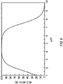
- FIG. 9 is a graph illustrating a relationship between the pH value of a liquid in the anode-side region 128 and the ratio of HCIO contained in an anode-side solution.
- the ratio of HClO means the molar ratio of HClO to the combined amount of HCIO and ClO - .
- FIG. 10 is a figure illustrating another exemplary operation of the electrolytic treatment apparatus 100.
- the injecting portion 102 in the present example injects, into the anode-side region 128, at least part of drainage discharged by the exhaust gas treatment apparatus 40.
- the injecting portion 102 may inject, into the anode-side region 128, entire drainage discharged by the exhaust gas treatment apparatus 40.
- the injecting portion 102 may use seawater as part of a liquid to be injected into the cathode-side region 126 and anode-side region 128.
- the injecting portion 102 may mix drainage discharged by the exhaust gas treatment apparatus 40 with seawater, and use the mixture as a liquid to be injected into the cathode-side region 126 and anode-side region 128.
Landscapes
- Chemical & Material Sciences (AREA)
- Engineering & Computer Science (AREA)
- Environmental & Geological Engineering (AREA)
- Chemical Kinetics & Catalysis (AREA)
- General Chemical & Material Sciences (AREA)
- Analytical Chemistry (AREA)
- Oil, Petroleum & Natural Gas (AREA)
- Health & Medical Sciences (AREA)
- Biomedical Technology (AREA)
- Life Sciences & Earth Sciences (AREA)
- Electrochemistry (AREA)
- Hydrology & Water Resources (AREA)
- Water Supply & Treatment (AREA)
- Organic Chemistry (AREA)
- Combustion & Propulsion (AREA)
- Ocean & Marine Engineering (AREA)
- Mechanical Engineering (AREA)
- Toxicology (AREA)
- Public Health (AREA)
- General Health & Medical Sciences (AREA)
- Water Treatment By Electricity Or Magnetism (AREA)
- Treating Waste Gases (AREA)
Claims (8)
- Elektrolytische Behandlungsvorrichtung (100) für ein Schiff, umfassend:einen Elektrolysebehälter (104) mit einer Kathode (106) und einer Anode (108);einen Einspritzabschnitt (102), der zum Einspritzen einer Flüssigkeit in den Elektrolysebehälter (104) konfiguriert ist;mindestens eine Membran (112), die einen Innenraum des Elektrolysebehälters (104) in eine kathodenseitige Region (126), welche die Kathode (106) umfasst, und eine anodenseitige Region (128), welche die Anode (108) umfasst, unterteilt und konfiguriert ist, eine Flüssigkeit in der kathodenseitigen Region (126) undeine Flüssigkeit in der anodenseitigen Region (128) elektrisch zu verbinden;einen kathodenseitigen Entladungsabschnitt (116), der konfiguriert ist, eine kathodenseitige Lösung, die in der kathodenseitigen Region (126) durch Elektrolysieren der Flüssigkeit erzeugt wird, einer Abgasbehandlungsvorrichtung (40) zuzuführen; undeinen anodenseitigen Entladungsabschnitt (118), der konfiguriert ist, eine anodenseitige Lösung, die in der anodenseitigen Region (128) durch Elektrolysieren der Flüssigkeit erzeugt wird, einer Sterilisationsvorrichtung (50) zuzuführen, dadurch gekennzeichnet, dass:ein Volumen der kathodenseitigen Region (126) und der anodenseitigen Region (128) veränderbar ist,ferner umfassend einen Volumensteuerungsabschnitt (114), der konfiguriert ist, ein Volumen der kathodenseitigen Region (126) und der anodenseitigen Region (128) basierend darauf zu steuern, ob das Schiff vor Anker liegt oder fährt, wobei:das Volumen der anodenseitigen Region (128) vergrößert wird, wenn das Schiff vor Anker liegt; unddas Volumen der kathodenseitigen Region (126) vergrößert wird, wenn das Schiff fährt.
- Elektrolytische Behandlungsvorrichtung (100) nach Anspruch 1, wobei eine Position der Membran (112) in dem Elektrolysebehälter (104) veränderbar ist.
- Elektrolytische Behandlungsvorrichtung (100) nach Anspruch 1, wobei die mindestens eine Membran (112) mehrere Membrane umfasst, die an verschiedenen Positionen in dem Elektrolysebehälter (104) einsetzbar und daraus entfernbar sind.
- Elektrolytische Behandlungsvorrichtung (100) nach einem der Ansprüche 1 bis 3, wobei der Einspritzabschnitt (102) konfiguriert ist, Meerwasser in den Elektrolysebehälter (104) einzuspritzen.
- Elektrolytische Behandlungsvorrichtung (100) nach einem der Ansprüche 1 bis 4, ferner umfassend einen Vorratstank für mindestens eine von der kathodenseitigen Lösung und der anodenseitigen Lösung, die aus dem Elektrolysebehälter (104) abgegeben wird.
- Elektrolytische Behandlungsvorrichtung (100) nach einem der Ansprüche 1 bis 5, wobei der anodenseitige Abgabeabschnitt eine Volumenstromrate pro Zeiteinheit der anodenseitigen Lösung basierend auf einem pH-Wert einer in die anodenseitige Region (128) eingespritzten Flüssigkeit oder einem pH-Wert der anodenseitigen Lösung steuert.
- Elektrolytische Behandlungsvorrichtung (100) nach einem der Ansprüche 1 bis 6, ferner umfassend eine Stromversorgung, die konfiguriert ist, die Kathode (106) und die Anode (108) mit elektrischer Energie zu versorgen, wobei
die Stromversorgung konfiguriert ist, einen zwischen der Anode (108) und der Kathode (106) fließenden Strom basierend auf einem pH-Wert einer in die anodenseitige Region (128) eingespritzten Flüssigkeit oder einem pH-Wert der anodenseitigen Lösung zu steuern. - Behandlungssystem (10), umfassend:die elektrolytische Behandlungsvorrichtung (100) nach einem der Ansprüche 1 bis 7;die Sterilisationsvorrichtung (50); unddie Abgasbehandlungsvorrichtung (40).
Applications Claiming Priority (2)
| Application Number | Priority Date | Filing Date | Title |
|---|---|---|---|
| JP2017126090 | 2017-06-28 | ||
| PCT/JP2018/017956 WO2019003651A1 (ja) | 2017-06-28 | 2018-05-09 | 電解処理装置および処理システム |
Publications (3)
| Publication Number | Publication Date |
|---|---|
| EP3536670A1 EP3536670A1 (de) | 2019-09-11 |
| EP3536670A4 EP3536670A4 (de) | 2020-04-01 |
| EP3536670B1 true EP3536670B1 (de) | 2021-11-10 |
Family
ID=64740624
Family Applications (1)
| Application Number | Title | Priority Date | Filing Date |
|---|---|---|---|
| EP18822643.5A Not-in-force EP3536670B1 (de) | 2017-06-28 | 2018-05-09 | Elektrolytische behandlungsvorrichtung und behandlungssystem |
Country Status (6)
| Country | Link |
|---|---|
| US (1) | US20190284064A1 (de) |
| EP (1) | EP3536670B1 (de) |
| JP (1) | JP6765532B2 (de) |
| KR (2) | KR102502150B1 (de) |
| CN (1) | CN110023248B (de) |
| WO (1) | WO2019003651A1 (de) |
Families Citing this family (5)
| Publication number | Priority date | Publication date | Assignee | Title |
|---|---|---|---|---|
| MY199723A (en) * | 2018-02-09 | 2023-11-20 | Nano Silver Mfg Sdn Bhd | An apparatus for cleaning exhaust smoke |
| CN110451611B (zh) * | 2019-08-18 | 2024-01-23 | 深圳市世清环保科技有限公司 | 复合式三维电解装置 |
| KR102171081B1 (ko) * | 2020-06-04 | 2020-10-28 | 김상곤 | 유해가스 처리장치 |
| WO2022185775A1 (ja) * | 2021-03-04 | 2022-09-09 | 富士電機株式会社 | 生成装置および排ガス処理システム |
| CN114570173B (zh) * | 2022-03-09 | 2023-01-24 | 南通理工学院 | 一种用于船舶尾气处理的电解法海水脱硫脱硝装置 |
Family Cites Families (14)
| Publication number | Priority date | Publication date | Assignee | Title |
|---|---|---|---|---|
| SU1470669A1 (ru) * | 1986-08-04 | 1989-04-07 | Донецкий Научно-Исследовательский Угольный Институт | Устройство дл электрохимической обработки шахтных вод |
| JP3275108B2 (ja) * | 1993-02-22 | 2002-04-15 | 日本インテック株式会社 | 電解水の生成装置 |
| JP3389625B2 (ja) * | 1993-02-26 | 2003-03-24 | 栗田工業株式会社 | 高温嫌気性処理方法 |
| JP2749258B2 (ja) * | 1994-03-04 | 1998-05-13 | 英雄 早川 | 排ガス処理方法及びその装置 |
| JP2004089770A (ja) | 2002-08-29 | 2004-03-25 | Masanori Tashiro | 排ガス浄化方法及びその装置 |
| JP2005342626A (ja) | 2004-06-03 | 2005-12-15 | Jfe Engineering Kk | バラスト水処理方法及び装置、該装置を搭載した船舶 |
| CN100368261C (zh) * | 2005-07-31 | 2008-02-13 | 大连海事大学 | 船舶压载水电解处理系统 |
| JP2008212334A (ja) * | 2007-03-02 | 2008-09-18 | Masaaki Arai | 空気清浄装置 |
| JP2009112996A (ja) * | 2007-11-09 | 2009-05-28 | Masanori Tashiro | 海水利用設備用水中の海洋生物殺滅方法及びその装置 |
| WO2011016781A1 (en) * | 2009-08-03 | 2011-02-10 | The Maritime And Port Authority Of Singapore | Emissions control system and method |
| KR101191147B1 (ko) * | 2010-07-30 | 2012-10-15 | 한국기계연구원 | 마이크로 버블을 이용한 전기분해식 선박 평형수 살균 처리장치 |
| KR101398053B1 (ko) * | 2011-08-23 | 2014-05-27 | (주) 테크윈 | 자동 산화-흡수제 생성장치를 구비한 스크러버 시스템 |
| EP2937131B1 (de) * | 2012-12-19 | 2018-04-04 | Fuji Electric Co., Ltd. | Abgasreinigungsvorrichtung |
| CN104772028B (zh) * | 2015-04-14 | 2017-01-04 | 大连海事大学 | 一种湿式船舶废气综合处理方法及装置 |
-
2018
- 2018-05-09 KR KR1020217027859A patent/KR102502150B1/ko active Active
- 2018-05-09 EP EP18822643.5A patent/EP3536670B1/de not_active Not-in-force
- 2018-05-09 KR KR1020197015977A patent/KR20190073546A/ko not_active Ceased
- 2018-05-09 JP JP2019526655A patent/JP6765532B2/ja active Active
- 2018-05-09 CN CN201880004715.0A patent/CN110023248B/zh not_active Expired - Fee Related
- 2018-05-09 WO PCT/JP2018/017956 patent/WO2019003651A1/ja not_active Ceased
-
2019
- 2019-06-03 US US16/429,074 patent/US20190284064A1/en not_active Abandoned
Non-Patent Citations (1)
| Title |
|---|
| None * |
Also Published As
| Publication number | Publication date |
|---|---|
| KR20210111358A (ko) | 2021-09-10 |
| JPWO2019003651A1 (ja) | 2019-11-07 |
| US20190284064A1 (en) | 2019-09-19 |
| KR20190073546A (ko) | 2019-06-26 |
| EP3536670A1 (de) | 2019-09-11 |
| EP3536670A4 (de) | 2020-04-01 |
| CN110023248A (zh) | 2019-07-16 |
| JP6765532B2 (ja) | 2020-10-07 |
| WO2019003651A1 (ja) | 2019-01-03 |
| KR102502150B1 (ko) | 2023-02-20 |
| CN110023248B (zh) | 2022-01-18 |
Similar Documents
| Publication | Publication Date | Title |
|---|---|---|
| EP3536670B1 (de) | Elektrolytische behandlungsvorrichtung und behandlungssystem | |
| KR101066674B1 (ko) | 전기분해 유닛과 이러한 전기분해 유닛을 이용한 선박의 발라스트 수 처리장치 | |
| AU2015268102A1 (en) | Improved chemical management for swimming pools | |
| JP4932529B2 (ja) | 水処理方法 | |
| JP2015208735A (ja) | 排ガスの処理方法及び処理装置 | |
| US20160194770A1 (en) | Electrolytic apparatus and method of producing electrolyzed water | |
| KR102025559B1 (ko) | 전기분해를 이용한 선박평형수 및 선박 배기 가스 처리 방법 | |
| JP2005177672A (ja) | 電解式オゾナイザ | |
| KR101891906B1 (ko) | 해수 전해 시스템 및 전해액 주입 방법 | |
| TW202419410A (zh) | 含氨油水之處理裝置及處理方法 | |
| JP2015213888A (ja) | 排ガスの処理方法及び処理装置 | |
| JP6086306B2 (ja) | バラスト水処理装置およびバラスト水処理方法 | |
| KR102640097B1 (ko) | 밸러스트수 처리 시스템 및 그것을 구비한 선박 | |
| KR100706118B1 (ko) | 차아염소산나트륨 발생장치용 염수 저장조의 물 보충장치 | |
| KR100675375B1 (ko) | 해산어 양식장의 수질관리시스템 | |
| ES2759623T3 (es) | Electrooxidación a presiones elevadas | |
| JP6300252B1 (ja) | 水処理システム、水処理システムの電極腐食抑制方法及び電極腐食抑制装置 | |
| KR102250773B1 (ko) | 산화제 생성 시스템 | |
| JP6927452B1 (ja) | 水処理方法及び水処理設備 | |
| KR20190054754A (ko) | 3실형 전해수 생성장치 | |
| JP2004305967A (ja) | 電解装置および電解方法 | |
| JP2004097855A (ja) | 水処理装置 | |
| KR100733541B1 (ko) | 전해식 밸러스터수 처리방법 및 처리장치 | |
| RU2241683C2 (ru) | Способ синтеза оксидантов из водного раствора хлорида натрия и устройство для его реализации | |
| KR101163344B1 (ko) | 전기분해 유닛을 이용한 선박의 발라스트 수 처리방법 |
Legal Events
| Date | Code | Title | Description |
|---|---|---|---|
| STAA | Information on the status of an ep patent application or granted ep patent |
Free format text: STATUS: THE INTERNATIONAL PUBLICATION HAS BEEN MADE |
|
| PUAI | Public reference made under article 153(3) epc to a published international application that has entered the european phase |
Free format text: ORIGINAL CODE: 0009012 |
|
| STAA | Information on the status of an ep patent application or granted ep patent |
Free format text: STATUS: REQUEST FOR EXAMINATION WAS MADE |
|
| 17P | Request for examination filed |
Effective date: 20190603 |
|
| AK | Designated contracting states |
Kind code of ref document: A1 Designated state(s): AL AT BE BG CH CY CZ DE DK EE ES FI FR GB GR HR HU IE IS IT LI LT LU LV MC MK MT NL NO PL PT RO RS SE SI SK SM TR |
|
| AX | Request for extension of the european patent |
Extension state: BA ME |
|
| RIN1 | Information on inventor provided before grant (corrected) |
Inventor name: INUI, TAKASHI Inventor name: OKU, TOMOHIRO Inventor name: ZUKERAN, AKINORI Inventor name: NAKADA, YUTA Inventor name: TOYOZUMI, HIROYUKI |
|
| RIN1 | Information on inventor provided before grant (corrected) |
Inventor name: INUI, TAKASHI Inventor name: ZUKERAN, AKINORI Inventor name: NAKADA, YUTA Inventor name: TOYOZUMI, HIROYUKI Inventor name: OKU, TOMOHIRO |
|
| RIC1 | Information provided on ipc code assigned before grant |
Ipc: C02F 103/18 20060101ALN20191121BHEP Ipc: B01D 53/92 20060101ALI20191121BHEP Ipc: B01D 53/14 20060101AFI20191121BHEP Ipc: C02F 1/461 20060101ALI20191121BHEP Ipc: B63J 4/00 20060101ALI20191121BHEP |
|
| A4 | Supplementary search report drawn up and despatched |
Effective date: 20200228 |
|
| RIC1 | Information provided on ipc code assigned before grant |
Ipc: B63J 4/00 20060101ALI20200224BHEP Ipc: B01D 53/14 20060101AFI20200224BHEP Ipc: C02F 1/461 20060101ALI20200224BHEP Ipc: C02F 103/18 20060101ALN20200224BHEP Ipc: B01D 53/92 20060101ALI20200224BHEP |
|
| DAV | Request for validation of the european patent (deleted) | ||
| DAX | Request for extension of the european patent (deleted) | ||
| STAA | Information on the status of an ep patent application or granted ep patent |
Free format text: STATUS: EXAMINATION IS IN PROGRESS |
|
| 17Q | First examination report despatched |
Effective date: 20201015 |
|
| REG | Reference to a national code |
Ref country code: DE Ref legal event code: R079 Ref document number: 602018026618 Country of ref document: DE Free format text: PREVIOUS MAIN CLASS: C02F0001461000 Ipc: B01D0053140000 |
|
| RIC1 | Information provided on ipc code assigned before grant |
Ipc: B01D 53/14 20060101AFI20210408BHEP Ipc: B01D 53/92 20060101ALI20210408BHEP Ipc: B63J 4/00 20060101ALI20210408BHEP Ipc: C02F 1/461 20060101ALI20210408BHEP Ipc: C02F 103/18 20060101ALN20210408BHEP |
|
| GRAP | Despatch of communication of intention to grant a patent |
Free format text: ORIGINAL CODE: EPIDOSNIGR1 |
|
| RIC1 | Information provided on ipc code assigned before grant |
Ipc: B01D 53/14 20060101AFI20210413BHEP Ipc: B01D 53/92 20060101ALI20210413BHEP Ipc: B63J 4/00 20060101ALI20210413BHEP Ipc: C02F 1/461 20060101ALI20210413BHEP Ipc: C02F 103/18 20060101ALN20210413BHEP |
|
| STAA | Information on the status of an ep patent application or granted ep patent |
Free format text: STATUS: GRANT OF PATENT IS INTENDED |
|
| INTG | Intention to grant announced |
Effective date: 20210520 |
|
| RIN1 | Information on inventor provided before grant (corrected) |
Inventor name: INUI, TAKASHI Inventor name: TOYOZUMI, HIROYUKI Inventor name: ZUKERAN, AKINORI Inventor name: OKU, TOMOHIRO Inventor name: NAKADA, YUTA |
|
| GRAS | Grant fee paid |
Free format text: ORIGINAL CODE: EPIDOSNIGR3 |
|
| GRAA | (expected) grant |
Free format text: ORIGINAL CODE: 0009210 |
|
| STAA | Information on the status of an ep patent application or granted ep patent |
Free format text: STATUS: THE PATENT HAS BEEN GRANTED |
|
| AK | Designated contracting states |
Kind code of ref document: B1 Designated state(s): AL AT BE BG CH CY CZ DE DK EE ES FI FR GB GR HR HU IE IS IT LI LT LU LV MC MK MT NL NO PL PT RO RS SE SI SK SM TR |
|
| REG | Reference to a national code |
Ref country code: GB Ref legal event code: FG4D |
|
| REG | Reference to a national code |
Ref country code: AT Ref legal event code: REF Ref document number: 1445552 Country of ref document: AT Kind code of ref document: T Effective date: 20211115 Ref country code: CH Ref legal event code: EP |
|
| REG | Reference to a national code |
Ref country code: DE Ref legal event code: R096 Ref document number: 602018026618 Country of ref document: DE |
|
| REG | Reference to a national code |
Ref country code: IE Ref legal event code: FG4D |
|
| REG | Reference to a national code |
Ref country code: GR Ref legal event code: EP Ref document number: 20220400090 Country of ref document: GR Effective date: 20220211 |
|
| REG | Reference to a national code |
Ref country code: LT Ref legal event code: MG9D |
|
| REG | Reference to a national code |
Ref country code: NL Ref legal event code: MP Effective date: 20211110 |
|
| REG | Reference to a national code |
Ref country code: AT Ref legal event code: MK05 Ref document number: 1445552 Country of ref document: AT Kind code of ref document: T Effective date: 20211110 |
|
| PG25 | Lapsed in a contracting state [announced via postgrant information from national office to epo] |
Ref country code: RS Free format text: LAPSE BECAUSE OF FAILURE TO SUBMIT A TRANSLATION OF THE DESCRIPTION OR TO PAY THE FEE WITHIN THE PRESCRIBED TIME-LIMIT Effective date: 20211110 Ref country code: LT Free format text: LAPSE BECAUSE OF FAILURE TO SUBMIT A TRANSLATION OF THE DESCRIPTION OR TO PAY THE FEE WITHIN THE PRESCRIBED TIME-LIMIT Effective date: 20211110 Ref country code: FI Free format text: LAPSE BECAUSE OF FAILURE TO SUBMIT A TRANSLATION OF THE DESCRIPTION OR TO PAY THE FEE WITHIN THE PRESCRIBED TIME-LIMIT Effective date: 20211110 Ref country code: BG Free format text: LAPSE BECAUSE OF FAILURE TO SUBMIT A TRANSLATION OF THE DESCRIPTION OR TO PAY THE FEE WITHIN THE PRESCRIBED TIME-LIMIT Effective date: 20220210 Ref country code: AT Free format text: LAPSE BECAUSE OF FAILURE TO SUBMIT A TRANSLATION OF THE DESCRIPTION OR TO PAY THE FEE WITHIN THE PRESCRIBED TIME-LIMIT Effective date: 20211110 |
|
| PG25 | Lapsed in a contracting state [announced via postgrant information from national office to epo] |
Ref country code: IS Free format text: LAPSE BECAUSE OF FAILURE TO SUBMIT A TRANSLATION OF THE DESCRIPTION OR TO PAY THE FEE WITHIN THE PRESCRIBED TIME-LIMIT Effective date: 20220310 Ref country code: SE Free format text: LAPSE BECAUSE OF FAILURE TO SUBMIT A TRANSLATION OF THE DESCRIPTION OR TO PAY THE FEE WITHIN THE PRESCRIBED TIME-LIMIT Effective date: 20211110 Ref country code: PT Free format text: LAPSE BECAUSE OF FAILURE TO SUBMIT A TRANSLATION OF THE DESCRIPTION OR TO PAY THE FEE WITHIN THE PRESCRIBED TIME-LIMIT Effective date: 20220310 Ref country code: PL Free format text: LAPSE BECAUSE OF FAILURE TO SUBMIT A TRANSLATION OF THE DESCRIPTION OR TO PAY THE FEE WITHIN THE PRESCRIBED TIME-LIMIT Effective date: 20211110 Ref country code: NO Free format text: LAPSE BECAUSE OF FAILURE TO SUBMIT A TRANSLATION OF THE DESCRIPTION OR TO PAY THE FEE WITHIN THE PRESCRIBED TIME-LIMIT Effective date: 20220210 Ref country code: NL Free format text: LAPSE BECAUSE OF FAILURE TO SUBMIT A TRANSLATION OF THE DESCRIPTION OR TO PAY THE FEE WITHIN THE PRESCRIBED TIME-LIMIT Effective date: 20211110 Ref country code: LV Free format text: LAPSE BECAUSE OF FAILURE TO SUBMIT A TRANSLATION OF THE DESCRIPTION OR TO PAY THE FEE WITHIN THE PRESCRIBED TIME-LIMIT Effective date: 20211110 Ref country code: HR Free format text: LAPSE BECAUSE OF FAILURE TO SUBMIT A TRANSLATION OF THE DESCRIPTION OR TO PAY THE FEE WITHIN THE PRESCRIBED TIME-LIMIT Effective date: 20211110 Ref country code: ES Free format text: LAPSE BECAUSE OF FAILURE TO SUBMIT A TRANSLATION OF THE DESCRIPTION OR TO PAY THE FEE WITHIN THE PRESCRIBED TIME-LIMIT Effective date: 20211110 |
|
| PG25 | Lapsed in a contracting state [announced via postgrant information from national office to epo] |
Ref country code: SM Free format text: LAPSE BECAUSE OF FAILURE TO SUBMIT A TRANSLATION OF THE DESCRIPTION OR TO PAY THE FEE WITHIN THE PRESCRIBED TIME-LIMIT Effective date: 20211110 Ref country code: SK Free format text: LAPSE BECAUSE OF FAILURE TO SUBMIT A TRANSLATION OF THE DESCRIPTION OR TO PAY THE FEE WITHIN THE PRESCRIBED TIME-LIMIT Effective date: 20211110 Ref country code: RO Free format text: LAPSE BECAUSE OF FAILURE TO SUBMIT A TRANSLATION OF THE DESCRIPTION OR TO PAY THE FEE WITHIN THE PRESCRIBED TIME-LIMIT Effective date: 20211110 Ref country code: EE Free format text: LAPSE BECAUSE OF FAILURE TO SUBMIT A TRANSLATION OF THE DESCRIPTION OR TO PAY THE FEE WITHIN THE PRESCRIBED TIME-LIMIT Effective date: 20211110 Ref country code: DK Free format text: LAPSE BECAUSE OF FAILURE TO SUBMIT A TRANSLATION OF THE DESCRIPTION OR TO PAY THE FEE WITHIN THE PRESCRIBED TIME-LIMIT Effective date: 20211110 Ref country code: CZ Free format text: LAPSE BECAUSE OF FAILURE TO SUBMIT A TRANSLATION OF THE DESCRIPTION OR TO PAY THE FEE WITHIN THE PRESCRIBED TIME-LIMIT Effective date: 20211110 |
|
| REG | Reference to a national code |
Ref country code: DE Ref legal event code: R097 Ref document number: 602018026618 Country of ref document: DE |
|
| PLBE | No opposition filed within time limit |
Free format text: ORIGINAL CODE: 0009261 |
|
| STAA | Information on the status of an ep patent application or granted ep patent |
Free format text: STATUS: NO OPPOSITION FILED WITHIN TIME LIMIT |
|
| 26N | No opposition filed |
Effective date: 20220811 |
|
| PG25 | Lapsed in a contracting state [announced via postgrant information from national office to epo] |
Ref country code: AL Free format text: LAPSE BECAUSE OF FAILURE TO SUBMIT A TRANSLATION OF THE DESCRIPTION OR TO PAY THE FEE WITHIN THE PRESCRIBED TIME-LIMIT Effective date: 20211110 |
|
| PG25 | Lapsed in a contracting state [announced via postgrant information from national office to epo] |
Ref country code: SI Free format text: LAPSE BECAUSE OF FAILURE TO SUBMIT A TRANSLATION OF THE DESCRIPTION OR TO PAY THE FEE WITHIN THE PRESCRIBED TIME-LIMIT Effective date: 20211110 |
|
| REG | Reference to a national code |
Ref country code: DE Ref legal event code: R119 Ref document number: 602018026618 Country of ref document: DE |
|
| REG | Reference to a national code |
Ref country code: CH Ref legal event code: PL |
|
| REG | Reference to a national code |
Ref country code: BE Ref legal event code: MM Effective date: 20220531 |
|
| GBPC | Gb: european patent ceased through non-payment of renewal fee |
Effective date: 20220509 |
|
| PG25 | Lapsed in a contracting state [announced via postgrant information from national office to epo] |
Ref country code: MC Free format text: LAPSE BECAUSE OF FAILURE TO SUBMIT A TRANSLATION OF THE DESCRIPTION OR TO PAY THE FEE WITHIN THE PRESCRIBED TIME-LIMIT Effective date: 20211110 Ref country code: LU Free format text: LAPSE BECAUSE OF NON-PAYMENT OF DUE FEES Effective date: 20220509 Ref country code: LI Free format text: LAPSE BECAUSE OF NON-PAYMENT OF DUE FEES Effective date: 20220531 Ref country code: CH Free format text: LAPSE BECAUSE OF NON-PAYMENT OF DUE FEES Effective date: 20220531 |
|
| PG25 | Lapsed in a contracting state [announced via postgrant information from national office to epo] |
Ref country code: IE Free format text: LAPSE BECAUSE OF NON-PAYMENT OF DUE FEES Effective date: 20220509 Ref country code: FR Free format text: LAPSE BECAUSE OF NON-PAYMENT OF DUE FEES Effective date: 20220531 |
|
| PG25 | Lapsed in a contracting state [announced via postgrant information from national office to epo] |
Ref country code: IT Free format text: LAPSE BECAUSE OF FAILURE TO SUBMIT A TRANSLATION OF THE DESCRIPTION OR TO PAY THE FEE WITHIN THE PRESCRIBED TIME-LIMIT Effective date: 20211110 Ref country code: GB Free format text: LAPSE BECAUSE OF NON-PAYMENT OF DUE FEES Effective date: 20220509 Ref country code: DE Free format text: LAPSE BECAUSE OF NON-PAYMENT OF DUE FEES Effective date: 20221201 Ref country code: BE Free format text: LAPSE BECAUSE OF NON-PAYMENT OF DUE FEES Effective date: 20220531 |
|
| PGFP | Annual fee paid to national office [announced via postgrant information from national office to epo] |
Ref country code: GR Payment date: 20230419 Year of fee payment: 6 |
|
| PG25 | Lapsed in a contracting state [announced via postgrant information from national office to epo] |
Ref country code: HU Free format text: LAPSE BECAUSE OF FAILURE TO SUBMIT A TRANSLATION OF THE DESCRIPTION OR TO PAY THE FEE WITHIN THE PRESCRIBED TIME-LIMIT; INVALID AB INITIO Effective date: 20180509 |
|
| PG25 | Lapsed in a contracting state [announced via postgrant information from national office to epo] |
Ref country code: MK Free format text: LAPSE BECAUSE OF FAILURE TO SUBMIT A TRANSLATION OF THE DESCRIPTION OR TO PAY THE FEE WITHIN THE PRESCRIBED TIME-LIMIT Effective date: 20211110 Ref country code: CY Free format text: LAPSE BECAUSE OF FAILURE TO SUBMIT A TRANSLATION OF THE DESCRIPTION OR TO PAY THE FEE WITHIN THE PRESCRIBED TIME-LIMIT Effective date: 20211110 |
|
| PG25 | Lapsed in a contracting state [announced via postgrant information from national office to epo] |
Ref country code: TR Free format text: LAPSE BECAUSE OF FAILURE TO SUBMIT A TRANSLATION OF THE DESCRIPTION OR TO PAY THE FEE WITHIN THE PRESCRIBED TIME-LIMIT Effective date: 20211110 |
|
| PG25 | Lapsed in a contracting state [announced via postgrant information from national office to epo] |
Ref country code: MT Free format text: LAPSE BECAUSE OF FAILURE TO SUBMIT A TRANSLATION OF THE DESCRIPTION OR TO PAY THE FEE WITHIN THE PRESCRIBED TIME-LIMIT Effective date: 20211110 |
|
| PG25 | Lapsed in a contracting state [announced via postgrant information from national office to epo] |
Ref country code: GR Free format text: LAPSE BECAUSE OF NON-PAYMENT OF DUE FEES Effective date: 20241204 |
|
| PG25 | Lapsed in a contracting state [announced via postgrant information from national office to epo] |
Ref country code: GR Free format text: LAPSE BECAUSE OF NON-PAYMENT OF DUE FEES Effective date: 20241204 |