EP3536670B1 - Electrolytic treatment device and treatment system - Google Patents
Electrolytic treatment device and treatment system Download PDFInfo
- Publication number
- EP3536670B1 EP3536670B1 EP18822643.5A EP18822643A EP3536670B1 EP 3536670 B1 EP3536670 B1 EP 3536670B1 EP 18822643 A EP18822643 A EP 18822643A EP 3536670 B1 EP3536670 B1 EP 3536670B1
- Authority
- EP
- European Patent Office
- Prior art keywords
- anode
- cathode
- side region
- treatment apparatus
- electrolytic
- Prior art date
- Legal status (The legal status is an assumption and is not a legal conclusion. Google has not performed a legal analysis and makes no representation as to the accuracy of the status listed.)
- Active
Links
- 239000007788 liquid Substances 0.000 claims description 53
- 239000013535 sea water Substances 0.000 claims description 22
- 238000007599 discharging Methods 0.000 claims description 16
- 230000001954 sterilising effect Effects 0.000 claims description 10
- 238000005192 partition Methods 0.000 claims description 3
- 239000000243 solution Substances 0.000 description 82
- 239000007789 gas Substances 0.000 description 67
- XLYOFNOQVPJJNP-UHFFFAOYSA-N water Substances O XLYOFNOQVPJJNP-UHFFFAOYSA-N 0.000 description 52
- 239000000126 substance Substances 0.000 description 36
- QWPPOHNGKGFGJK-UHFFFAOYSA-N hypochlorous acid Chemical compound ClO QWPPOHNGKGFGJK-UHFFFAOYSA-N 0.000 description 15
- 230000008030 elimination Effects 0.000 description 11
- 238000003379 elimination reaction Methods 0.000 description 11
- 238000006243 chemical reaction Methods 0.000 description 10
- 239000002253 acid Substances 0.000 description 5
- 230000002378 acidificating effect Effects 0.000 description 4
- 238000010586 diagram Methods 0.000 description 4
- 238000002347 injection Methods 0.000 description 4
- 239000007924 injection Substances 0.000 description 4
- BVKZGUZCCUSVTD-UHFFFAOYSA-M Bicarbonate Chemical compound OC([O-])=O BVKZGUZCCUSVTD-UHFFFAOYSA-M 0.000 description 3
- 239000007864 aqueous solution Substances 0.000 description 3
- 230000007423 decrease Effects 0.000 description 3
- -1 hypochlorite ions Chemical class 0.000 description 3
- 239000001095 magnesium carbonate Substances 0.000 description 3
- ZLNQQNXFFQJAID-UHFFFAOYSA-L magnesium carbonate Chemical group [Mg+2].[O-]C([O-])=O ZLNQQNXFFQJAID-UHFFFAOYSA-L 0.000 description 3
- 229910000021 magnesium carbonate Inorganic materials 0.000 description 3
- VTHJTEIRLNZDEV-UHFFFAOYSA-L magnesium dihydroxide Chemical compound [OH-].[OH-].[Mg+2] VTHJTEIRLNZDEV-UHFFFAOYSA-L 0.000 description 3
- 239000000347 magnesium hydroxide Substances 0.000 description 3
- 229910001862 magnesium hydroxide Inorganic materials 0.000 description 3
- 238000010349 cathodic reaction Methods 0.000 description 2
- XLYOFNOQVPJJNP-ZSJDYOACSA-N heavy water Substances [2H]O[2H] XLYOFNOQVPJJNP-ZSJDYOACSA-N 0.000 description 2
- WQYVRQLZKVEZGA-UHFFFAOYSA-N hypochlorite Inorganic materials Cl[O-] WQYVRQLZKVEZGA-UHFFFAOYSA-N 0.000 description 2
- 239000000203 mixture Substances 0.000 description 2
- 238000000638 solvent extraction Methods 0.000 description 2
- 241000894006 Bacteria Species 0.000 description 1
- OKTJSMMVPCPJKN-UHFFFAOYSA-N Carbon Chemical compound [C] OKTJSMMVPCPJKN-UHFFFAOYSA-N 0.000 description 1
- 229920000297 Rayon Polymers 0.000 description 1
- 150000007513 acids Chemical class 0.000 description 1
- 244000052616 bacterial pathogen Species 0.000 description 1
- 229910052799 carbon Inorganic materials 0.000 description 1
- 210000001072 colon Anatomy 0.000 description 1
- TXKMVPPZCYKFAC-UHFFFAOYSA-N disulfur monoxide Inorganic materials O=S=S TXKMVPPZCYKFAC-UHFFFAOYSA-N 0.000 description 1
- 238000005868 electrolysis reaction Methods 0.000 description 1
- 238000001704 evaporation Methods 0.000 description 1
- 230000008020 evaporation Effects 0.000 description 1
- 239000004744 fabric Substances 0.000 description 1
- 239000000835 fiber Substances 0.000 description 1
- 238000009434 installation Methods 0.000 description 1
- 150000002500 ions Chemical class 0.000 description 1
- 239000000463 material Substances 0.000 description 1
- 238000000034 method Methods 0.000 description 1
- 150000004767 nitrides Chemical class 0.000 description 1
- 239000002964 rayon Substances 0.000 description 1
- 239000007921 spray Substances 0.000 description 1
- 238000004659 sterilization and disinfection Methods 0.000 description 1
- XTQHKBHJIVJGKJ-UHFFFAOYSA-N sulfur monoxide Chemical compound S=O XTQHKBHJIVJGKJ-UHFFFAOYSA-N 0.000 description 1
- 229910052815 sulfur oxide Inorganic materials 0.000 description 1
- 239000010409 thin film Substances 0.000 description 1
- 238000009941 weaving Methods 0.000 description 1
Images


Classifications
-
- C—CHEMISTRY; METALLURGY
- C02—TREATMENT OF WATER, WASTE WATER, SEWAGE, OR SLUDGE
- C02F—TREATMENT OF WATER, WASTE WATER, SEWAGE, OR SLUDGE
- C02F1/00—Treatment of water, waste water, or sewage
- C02F1/46—Treatment of water, waste water, or sewage by electrochemical methods
- C02F1/461—Treatment of water, waste water, or sewage by electrochemical methods by electrolysis
- C02F1/46104—Devices therefor; Their operating or servicing
-
- B—PERFORMING OPERATIONS; TRANSPORTING
- B63—SHIPS OR OTHER WATERBORNE VESSELS; RELATED EQUIPMENT
- B63J—AUXILIARIES ON VESSELS
- B63J4/00—Arrangements of installations for treating ballast water, waste water, sewage, sludge, or refuse, or for preventing environmental pollution not otherwise provided for
- B63J4/002—Arrangements of installations for treating ballast water, waste water, sewage, sludge, or refuse, or for preventing environmental pollution not otherwise provided for for treating ballast water
-
- C—CHEMISTRY; METALLURGY
- C02—TREATMENT OF WATER, WASTE WATER, SEWAGE, OR SLUDGE
- C02F—TREATMENT OF WATER, WASTE WATER, SEWAGE, OR SLUDGE
- C02F1/00—Treatment of water, waste water, or sewage
- C02F1/46—Treatment of water, waste water, or sewage by electrochemical methods
- C02F1/461—Treatment of water, waste water, or sewage by electrochemical methods by electrolysis
-
- B—PERFORMING OPERATIONS; TRANSPORTING
- B01—PHYSICAL OR CHEMICAL PROCESSES OR APPARATUS IN GENERAL
- B01D—SEPARATION
- B01D47/00—Separating dispersed particles from gases, air or vapours by liquid as separating agent
- B01D47/06—Spray cleaning
-
- B—PERFORMING OPERATIONS; TRANSPORTING
- B01—PHYSICAL OR CHEMICAL PROCESSES OR APPARATUS IN GENERAL
- B01D—SEPARATION
- B01D53/00—Separation of gases or vapours; Recovering vapours of volatile solvents from gases; Chemical or biological purification of waste gases, e.g. engine exhaust gases, smoke, fumes, flue gases, aerosols
- B01D53/14—Separation of gases or vapours; Recovering vapours of volatile solvents from gases; Chemical or biological purification of waste gases, e.g. engine exhaust gases, smoke, fumes, flue gases, aerosols by absorption
- B01D53/1493—Selection of liquid materials for use as absorbents
-
- B—PERFORMING OPERATIONS; TRANSPORTING
- B01—PHYSICAL OR CHEMICAL PROCESSES OR APPARATUS IN GENERAL
- B01D—SEPARATION
- B01D53/00—Separation of gases or vapours; Recovering vapours of volatile solvents from gases; Chemical or biological purification of waste gases, e.g. engine exhaust gases, smoke, fumes, flue gases, aerosols
- B01D53/14—Separation of gases or vapours; Recovering vapours of volatile solvents from gases; Chemical or biological purification of waste gases, e.g. engine exhaust gases, smoke, fumes, flue gases, aerosols by absorption
- B01D53/18—Absorbing units; Liquid distributors therefor
-
- B—PERFORMING OPERATIONS; TRANSPORTING
- B01—PHYSICAL OR CHEMICAL PROCESSES OR APPARATUS IN GENERAL
- B01D—SEPARATION
- B01D53/00—Separation of gases or vapours; Recovering vapours of volatile solvents from gases; Chemical or biological purification of waste gases, e.g. engine exhaust gases, smoke, fumes, flue gases, aerosols
- B01D53/34—Chemical or biological purification of waste gases
- B01D53/46—Removing components of defined structure
- B01D53/48—Sulfur compounds
- B01D53/50—Sulfur oxides
-
- B—PERFORMING OPERATIONS; TRANSPORTING
- B01—PHYSICAL OR CHEMICAL PROCESSES OR APPARATUS IN GENERAL
- B01D—SEPARATION
- B01D53/00—Separation of gases or vapours; Recovering vapours of volatile solvents from gases; Chemical or biological purification of waste gases, e.g. engine exhaust gases, smoke, fumes, flue gases, aerosols
- B01D53/34—Chemical or biological purification of waste gases
- B01D53/46—Removing components of defined structure
- B01D53/54—Nitrogen compounds
- B01D53/56—Nitrogen oxides
-
- B—PERFORMING OPERATIONS; TRANSPORTING
- B01—PHYSICAL OR CHEMICAL PROCESSES OR APPARATUS IN GENERAL
- B01D—SEPARATION
- B01D53/00—Separation of gases or vapours; Recovering vapours of volatile solvents from gases; Chemical or biological purification of waste gases, e.g. engine exhaust gases, smoke, fumes, flue gases, aerosols
- B01D53/34—Chemical or biological purification of waste gases
- B01D53/74—General processes for purification of waste gases; Apparatus or devices specially adapted therefor
- B01D53/77—Liquid phase processes
- B01D53/78—Liquid phase processes with gas-liquid contact
-
- B—PERFORMING OPERATIONS; TRANSPORTING
- B01—PHYSICAL OR CHEMICAL PROCESSES OR APPARATUS IN GENERAL
- B01D—SEPARATION
- B01D53/00—Separation of gases or vapours; Recovering vapours of volatile solvents from gases; Chemical or biological purification of waste gases, e.g. engine exhaust gases, smoke, fumes, flue gases, aerosols
- B01D53/34—Chemical or biological purification of waste gases
- B01D53/74—General processes for purification of waste gases; Apparatus or devices specially adapted therefor
- B01D53/77—Liquid phase processes
- B01D53/79—Injecting reactants
-
- B—PERFORMING OPERATIONS; TRANSPORTING
- B01—PHYSICAL OR CHEMICAL PROCESSES OR APPARATUS IN GENERAL
- B01D—SEPARATION
- B01D53/00—Separation of gases or vapours; Recovering vapours of volatile solvents from gases; Chemical or biological purification of waste gases, e.g. engine exhaust gases, smoke, fumes, flue gases, aerosols
- B01D53/34—Chemical or biological purification of waste gases
- B01D53/92—Chemical or biological purification of waste gases of engine exhaust gases
-
- C—CHEMISTRY; METALLURGY
- C02—TREATMENT OF WATER, WASTE WATER, SEWAGE, OR SLUDGE
- C02F—TREATMENT OF WATER, WASTE WATER, SEWAGE, OR SLUDGE
- C02F1/00—Treatment of water, waste water, or sewage
- C02F1/46—Treatment of water, waste water, or sewage by electrochemical methods
- C02F1/461—Treatment of water, waste water, or sewage by electrochemical methods by electrolysis
- C02F1/46104—Devices therefor; Their operating or servicing
- C02F1/4618—Devices therefor; Their operating or servicing for producing "ionised" acidic or basic water
-
- C—CHEMISTRY; METALLURGY
- C02—TREATMENT OF WATER, WASTE WATER, SEWAGE, OR SLUDGE
- C02F—TREATMENT OF WATER, WASTE WATER, SEWAGE, OR SLUDGE
- C02F1/00—Treatment of water, waste water, or sewage
- C02F1/46—Treatment of water, waste water, or sewage by electrochemical methods
- C02F1/461—Treatment of water, waste water, or sewage by electrochemical methods by electrolysis
- C02F1/467—Treatment of water, waste water, or sewage by electrochemical methods by electrolysis by electrochemical disinfection; by electrooxydation or by electroreduction
- C02F1/4672—Treatment of water, waste water, or sewage by electrochemical methods by electrolysis by electrochemical disinfection; by electrooxydation or by electroreduction by electrooxydation
-
- C—CHEMISTRY; METALLURGY
- C02—TREATMENT OF WATER, WASTE WATER, SEWAGE, OR SLUDGE
- C02F—TREATMENT OF WATER, WASTE WATER, SEWAGE, OR SLUDGE
- C02F1/00—Treatment of water, waste water, or sewage
- C02F1/46—Treatment of water, waste water, or sewage by electrochemical methods
- C02F1/461—Treatment of water, waste water, or sewage by electrochemical methods by electrolysis
- C02F1/46104—Devices therefor; Their operating or servicing
- C02F1/4618—Devices therefor; Their operating or servicing for producing "ionised" acidic or basic water
- C02F2001/46185—Devices therefor; Their operating or servicing for producing "ionised" acidic or basic water only anodic or acidic water, e.g. for oxidizing or sterilizing
-
- C—CHEMISTRY; METALLURGY
- C02—TREATMENT OF WATER, WASTE WATER, SEWAGE, OR SLUDGE
- C02F—TREATMENT OF WATER, WASTE WATER, SEWAGE, OR SLUDGE
- C02F1/00—Treatment of water, waste water, or sewage
- C02F1/46—Treatment of water, waste water, or sewage by electrochemical methods
- C02F1/461—Treatment of water, waste water, or sewage by electrochemical methods by electrolysis
- C02F1/46104—Devices therefor; Their operating or servicing
- C02F1/4618—Devices therefor; Their operating or servicing for producing "ionised" acidic or basic water
- C02F2001/4619—Devices therefor; Their operating or servicing for producing "ionised" acidic or basic water only cathodic or alkaline water, e.g. for reducing
-
- C—CHEMISTRY; METALLURGY
- C02—TREATMENT OF WATER, WASTE WATER, SEWAGE, OR SLUDGE
- C02F—TREATMENT OF WATER, WASTE WATER, SEWAGE, OR SLUDGE
- C02F2103/00—Nature of the water, waste water, sewage or sludge to be treated
- C02F2103/008—Originating from marine vessels, ships and boats, e.g. bilge water or ballast water
-
- C—CHEMISTRY; METALLURGY
- C02—TREATMENT OF WATER, WASTE WATER, SEWAGE, OR SLUDGE
- C02F—TREATMENT OF WATER, WASTE WATER, SEWAGE, OR SLUDGE
- C02F2103/00—Nature of the water, waste water, sewage or sludge to be treated
- C02F2103/18—Nature of the water, waste water, sewage or sludge to be treated from the purification of gaseous effluents
-
- C—CHEMISTRY; METALLURGY
- C02—TREATMENT OF WATER, WASTE WATER, SEWAGE, OR SLUDGE
- C02F—TREATMENT OF WATER, WASTE WATER, SEWAGE, OR SLUDGE
- C02F2201/00—Apparatus for treatment of water, waste water or sewage
- C02F2201/46—Apparatus for electrochemical processes
- C02F2201/461—Electrolysis apparatus
- C02F2201/46105—Details relating to the electrolytic devices
- C02F2201/4611—Fluid flow
-
- C—CHEMISTRY; METALLURGY
- C02—TREATMENT OF WATER, WASTE WATER, SEWAGE, OR SLUDGE
- C02F—TREATMENT OF WATER, WASTE WATER, SEWAGE, OR SLUDGE
- C02F2201/00—Apparatus for treatment of water, waste water or sewage
- C02F2201/46—Apparatus for electrochemical processes
- C02F2201/461—Electrolysis apparatus
- C02F2201/46105—Details relating to the electrolytic devices
- C02F2201/46115—Electrolytic cell with membranes or diaphragms
-
- C—CHEMISTRY; METALLURGY
- C02—TREATMENT OF WATER, WASTE WATER, SEWAGE, OR SLUDGE
- C02F—TREATMENT OF WATER, WASTE WATER, SEWAGE, OR SLUDGE
- C02F2201/00—Apparatus for treatment of water, waste water or sewage
- C02F2201/46—Apparatus for electrochemical processes
- C02F2201/461—Electrolysis apparatus
- C02F2201/46105—Details relating to the electrolytic devices
- C02F2201/4612—Controlling or monitoring
- C02F2201/46125—Electrical variables
- C02F2201/4614—Current
Definitions
- the present invention relates to an electrolytic treatment apparatus for a ship, and a treatment system.
- Patent Literature 1 Conventional known scrubber apparatuses treat exhaust gases on ships or the like using solutions containing alkaline substances (see Patent Literature 1, for example). In addition, known treatment apparatuses sterilize ballast water or the like on ships (see Patent Literature 2 or 3, for example). Further examples of related art are described in Patent Literature 4 and 5.
- apparatuses installed on ships or the like have small sizes.
- a first aspect of the present invention provides an electrolytic treatment apparatus according to claim 1.
- the electrolytic treatment apparatus includes an electrolytic tank having a cathode and an anode.
- the electrolytic treatment apparatus includes an injecting portion that injects a liquid into the electrolytic tank.
- the electrolytic treatment apparatus includes at least one diaphragm that partitions an inner space of the electrolytic tank into a cathode-side region including the cathode and an anode-side region including the anode, and makes a liquid in the cathode-side region and a liquid in the anode-side region electrically connected.
- the electrolytic treatment apparatus includes a cathode-side discharging portion that supplies, to an exhaust gas treatment apparatus, a cathode-side solution generated in the cathode-side region by electrolyzing the liquid.
- the electrolytic treatment apparatus includes an anode-side discharging portion that supplies, to a sterilizing apparatus, an anode-side solution generated in the anode-side region by electrolyzing the liquid.
- the sterilizing apparatus may include a ballast tank to store ballast water on a ship.
- a volume of at least one of the cathode-side region and the anode-side region is variable.
- a position of the diaphragm in the electrolytic tank may be variable.
- the at least one diaphragm may include a plurality of diaphragms that are insertable and removable at different positions in the electrolytic tank.
- the injecting portion may inject seawater into the electrolytic tank.
- the exhaust gas treatment apparatus may eliminate a targeted elimination substance contained in an exhaust gas by bringing the cathode-side solution into contact with the exhaust gas.
- the injecting portion may inject, as at least part of the liquid and into the electrolytic tank, drainage discharged by the exhaust gas treatment apparatus.
- the injecting portion may inject, into the anode-side region, at least part of drainage discharged by the exhaust gas treatment apparatus.
- the electrolytic treatment apparatus may include a storage tank provided for at least one of the cathode-side solution and the anode-side solution discharged by the electrolytic tank.
- the electrolytic treatment apparatus includes a volume control portion that controls a volume of at least one of the cathode-side region and the anode-side region based on an operation condition of a ship on which the electrolytic treatment apparatus is installed.
- the anode-side discharging portion may control a volumetric flow rate per unit time of the anode-side solution based on a pH value of a liquid injected into the anode-side region or a pH value of the anode-side solution.
- the electrolytic treatment apparatus may include a power supply that supplies electrical power to the cathode and the anode.
- the power supply may control a current flowing between the anode and the cathode based on a pH value of a liquid injected into the anode-side region or a pH value of the anode-side solution.
- a second aspect of the present invention provides a treatment system including: the electrolytic treatment apparatus according to the first aspect; the sterilizing apparatus; and the exhaust gas treatment apparatus.
- FIG. 1 is a block diagram illustrating an exemplary treatment system 10 according to one embodiment of the present invention.
- the treatment system 10 performs electrolytic treatment on a liquid to thereby generate a cathode-side solution containing an alkaline substance, and an anode-side solution containing an acid.
- an exemplary liquid used in the treatment system 10 is seawater, it may be any liquid as along as it can generate an alkaline substance and an acid as a result of electrolytic treatment.
- the treatment system 10 is installed on a ship.
- the treatment system 10 includes a pump 20, a power supply 30, an exhaust gas treatment apparatus 40, a ballast water treatment apparatus 50, and an electrolytic treatment apparatus 100.
- the pump 20 supplies a liquid to the electrolytic treatment apparatus 100.
- the pump 20 in the present example pumps up seawater from the sea, and supplies the seawater to the electrolytic treatment apparatus 100.
- the electrolytic treatment apparatus 100 performs electrolytic treatment on the liquid supplied from the pump 20.
- the power supply 30 supplies electrical power to a cathode and an anode provided to the electrolytic treatment apparatus 100.
- the electrolytic treatment apparatus 100 supplies, to the exhaust gas treatment apparatus 40, a cathode-side solution generated near the cathode as a result of the electrolytic treatment.
- the electrolytic treatment apparatus 100 supplies, to the ballast water treatment apparatus 50, an anode-side solution generated near the anode as a result of the electrolytic treatment.
- the exhaust gas treatment apparatus 40 uses the cathode-side solution to eliminate a targeted elimination substance contained in an exhaust gas generated by an exhaust gas source.
- the exhaust gas treatment apparatus 40 brings the exhaust gas into contact with the cathode-side solution to thereby trigger a reaction between the targeted elimination substance contained in the exhaust gas, and an alkaline substance contained in the cathode-side solution, and eliminate the targeted elimination substance.
- the exhaust gas treatment apparatus 40 sprays the cathode-side solution into a housing in which the exhaust gas flows to thereby bring the exhaust gas into contact with the cathode-side solution.
- the exhaust gas treatment apparatus 40 discharges, to the outside, the treated gas from which the targeted elimination substance is eliminated.
- the exhaust gas source is a propulsion engine of a ship, a power-generating apparatus (for example, a power-generating engine) provided on a ship, a boiler provided on a ship, or the like.
- the targeted elimination substance is a sulfur oxide (Sox), or a nitride oxide (NOx).
- the alkaline substance is MgCO 3 or Mg(OH) 2 .
- the ballast water treatment apparatus 50 is an exemplary sterilizing apparatus that sterilizes ballast water on a ship using an anode-side solution.
- the ballast water treatment apparatus 50 may sterilize ballast water by mixing the anode-side solution into the ballast water.
- the ballast water treatment apparatus 50 may include a ballast tank 52 that stores sterilized ballast water.
- the ballast water treatment apparatus 50 may include a sterilizing portion that sterilizes ballast water.
- the ballast water treatment apparatus 50 may further include a filter or the like that eliminates predetermined substances and objects contained in ballast water.
- the treatment system 10 may further include a pump that pumps up seawater to be used as ballast water, and supplies the seawater to the ballast water treatment apparatus 50.
- the ballast water treatment apparatus 50 may store the anode-side solution itself as ballast water in the ballast tank 52.
- an acid contained in the anode-side solution is a hypochlorous acid (HClO) or hypochlorite ions (ClO - ). These acids enable elimination of plankton or bacteria such as colon bacilli that are contained in ballast water.
- FIG. 2 is a schematic view illustrating an electrolytic treatment apparatus 100, outside of the scope of the present invention.
- the electrolytic treatment apparatus 100 includes an electrolytic tank 104, a diaphragm 112, an injecting portion 102, a cathode-side discharging portion 116, and an anode-side discharging portion 118.
- the injecting portion 102 injects a liquid 110 into the electrolytic tank 104.
- the injecting portion 102 is a pipe through which the liquid 110 is conveyed.
- the liquid 110 in the present example is seawater.
- the electrolytic tank 104 stores the liquid 110.
- a cathode 106 and an anode 108 are inserted into the electrolytic tank 104.
- the cathode 106 and anode 108 are formed of a carbon-containing material, for example. Predetermined electrical power is applied to the cathode 106 and anode 108 by the power supply 30.
- the diaphragm 112 makes a liquid in the cathode-side region 126 and a liquid in the anode-side region 128 electrically connected such that a current can flow between the cathode 106 and the anode 108.
- the injecting portion 102 may inject seawater into both the cathode-side region 126 and the anode-side region 128.
- the diaphragm 112 is a fabric. More specific examples of the diaphragm 112 are those formed by weaving chemical fibers into a thin film, such as Tetoron or rayon. By immersing such a diaphragm 112 in the liquid 110, it becomes possible to make the cathode 106 and the anode 108 electrically connected while at the same time suppressing movement of a liquid.
- OH - generated at the cathode reacts with HCO 3 - in seawater to generate CO 3 2- .
- C0 3 2- reacts with Mg 2+ in seawater to generate MgCO 3 , which is an alkaline substance.
- OH - generated at the cathode reacts with Mg 2+ in seawater to generate Mg(OH) 2 , which is an alkaline substance.
- the cathode-side discharging portion 116 supplies, to the exhaust gas treatment apparatus 40, the cathode-side solution generated in the cathode-side region 126 by electrolyzing the liquid 110.
- the anode-side discharging portion 118 supplies, to the ballast water treatment apparatus 50, the anode-side solution generated in the anode-side region 128 by electrolyzing the liquid 110.
- the cathode-side discharging portion 116 and anode-side discharging portion 118 may be discharge ports provided to the electrolytic tank 104.
- the exhaust gas treatment apparatus 40 may release, to the sea, the cathode-side solution (drainage) with which an exhaust gas was treated, or may supply it back to the electrolytic treatment apparatus 100.
- the treatment system 10 may have two lines including a line for releasing drainage of the exhaust gas treatment apparatus 40 to the sea, and a line for supplying it back to the electrolytic treatment apparatus 100.
- the exhaust gas treatment apparatus 40 releases drainage to the sea in a sea area where it is allowed to release drainage. If drainage is released to the sea, bound substances of acidic substances and a targeted elimination substance contained in the drainage (for example, discharge-restricted substances) may be eliminated using a filter or the like, or the pH value of the drainage may be adjusted to fall within a predetermined range using a neutralizer or the like.
- the exhaust gas treatment apparatus 40 supplies drainage back to the electrolytic treatment apparatus 100 in a sea area where it is not allowed to release drainage.
- the mode in which drainage of the exhaust gas treatment apparatus 40 is released to the sea is referred to as an open driving mode
- the mode in which drainage is supplied back to the electrolytic treatment apparatus 100 is referred to as a closed driving mode.
- the position of the diaphragm 112 in the electrolytic tank 104 is variable.
- the volume control portion 114 controls the position of the diaphragm 112 to thereby control the volumes of both the cathode-side region 126 and the anode-side region 128.
- the volumes of the cathode-side region 126 and the anode-side region 128 may be able to be varied by another method.
- the volume of at least one of the cathode-side region 126 and the anode-side region 128 may be changed by moving the outer wall of the electrolytic tank 104.
- an increase of the volume of the anode-side region 128 decreases the volume of the cathode-side region 126.
- the amount of exhaust gas discharged from a propulsion engine or the like of the ship is not so large. Because of this, lowering the volumetric flow rate of the cathode-side solution, and reducing the volume of the cathode-side region 126 do not give rise to problems.
- volume control portion 114 may be a general-purpose computer.
- the computer has an installed program for causing the computer to function as the volume control portion 114.
- the volume control portion 114 may be a dedicated circuit or apparatus to function as the volume control portion 114.
- the injecting portion 102 may compensate for the amount of lost liquid by supplying seawater or ballast water into the cathode-side region 126.
- the injecting portion 102 may inject, into the anode-side region 128, ballast water in an amount corresponding to the anode-side solution discharged from the anode-side region 128.
- ballast water seawater pumped up by the pump 20 may be used.
- the anode-side solution is preferably supplied not to the ballast tank 52, but to a storage tank.
- the volume control portion 114 may increase the volume of the cathode-side region 126, and reduce the volume of the anode-side region 128. Thereby, targeted elimination substances contained in an exhaust gas can be eliminated efficiently using the cathode-side solution having an alkaline-substance concentration increased by the electrolytic treatment apparatus 100.
- the anode-side solution may be stored in advance in a storage tank. The stored anode-side solution can be used in sterilization of ballast water.
- the volume control portion 114 may maximize the volume of the cathode-side region 126, and minimize the volume of the anode-side region 128.
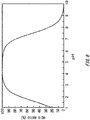
- FIG. 9 is a graph illustrating a relationship between the pH value of a liquid in the anode-side region 128 and the ratio of HCIO contained in an anode-side solution.
- the ratio of HClO means the molar ratio of HClO to the combined amount of HCIO and ClO - .
- FIG. 10 is a figure illustrating another exemplary operation of the electrolytic treatment apparatus 100.
- the injecting portion 102 in the present example injects, into the anode-side region 128, at least part of drainage discharged by the exhaust gas treatment apparatus 40.
- the injecting portion 102 may inject, into the anode-side region 128, entire drainage discharged by the exhaust gas treatment apparatus 40.
- the injecting portion 102 may use seawater as part of a liquid to be injected into the cathode-side region 126 and anode-side region 128.
- the injecting portion 102 may mix drainage discharged by the exhaust gas treatment apparatus 40 with seawater, and use the mixture as a liquid to be injected into the cathode-side region 126 and anode-side region 128.
Description
- The present invention relates to an electrolytic treatment apparatus for a ship, and a treatment system.
- Conventional known scrubber apparatuses treat exhaust gases on ships or the like using solutions containing alkaline substances (see Patent Literature 1, for example). In addition, known treatment apparatuses sterilize ballast water or the like on ships (see
Patent Literature Patent Literature - Patent Literature 1:
Japanese Patent Application Publication No. JP 2004-89770 - Patent Literature 2:
Japanese Patent Application Publication No. JP 2005-342626 - Patent Literature 3:
International Patent Application No. WO 2011/016781 A1 - Patent Literature 4:
Soviet Union Patent Application No. SU 1 470 669 A1 - Patent Literature 5:
Japanese Patent Application No. JP H06-246267 A - Preferably, apparatuses installed on ships or the like have small sizes.
- In order to solve the above-mentioned drawbacks, a first aspect of the present invention provides an electrolytic treatment apparatus according to claim 1. The electrolytic treatment apparatus includes an electrolytic tank having a cathode and an anode. The electrolytic treatment apparatus includes an injecting portion that injects a liquid into the electrolytic tank. The electrolytic treatment apparatus includes at least one diaphragm that partitions an inner space of the electrolytic tank into a cathode-side region including the cathode and an anode-side region including the anode, and makes a liquid in the cathode-side region and a liquid in the anode-side region electrically connected. The electrolytic treatment apparatus includes a cathode-side discharging portion that supplies, to an exhaust gas treatment apparatus, a cathode-side solution generated in the cathode-side region by electrolyzing the liquid. The electrolytic treatment apparatus includes an anode-side discharging portion that supplies, to a sterilizing apparatus, an anode-side solution generated in the anode-side region by electrolyzing the liquid.
- The sterilizing apparatus may include a ballast tank to store ballast water on a ship. A volume of at least one of the cathode-side region and the anode-side region is variable. A position of the diaphragm in the electrolytic tank may be variable. The at least one diaphragm may include a plurality of diaphragms that are insertable and removable at different positions in the electrolytic tank.
- The injecting portion may inject seawater into the electrolytic tank. The exhaust gas treatment apparatus may eliminate a targeted elimination substance contained in an exhaust gas by bringing the cathode-side solution into contact with the exhaust gas. The injecting portion may inject, as at least part of the liquid and into the electrolytic tank, drainage discharged by the exhaust gas treatment apparatus. The injecting portion may inject, into the anode-side region, at least part of drainage discharged by the exhaust gas treatment apparatus.
- The electrolytic treatment apparatus may include a storage tank provided for at least one of the cathode-side solution and the anode-side solution discharged by the electrolytic tank.
- The electrolytic treatment apparatus includes a volume control portion that controls a volume of at least one of the cathode-side region and the anode-side region based on an operation condition of a ship on which the electrolytic treatment apparatus is installed.
- The anode-side discharging portion may control a volumetric flow rate per unit time of the anode-side solution based on a pH value of a liquid injected into the anode-side region or a pH value of the anode-side solution. The electrolytic treatment apparatus may include a power supply that supplies electrical power to the cathode and the anode. The power supply may control a current flowing between the anode and the cathode based on a pH value of a liquid injected into the anode-side region or a pH value of the anode-side solution.
- A second aspect of the present invention provides a treatment system including: the electrolytic treatment apparatus according to the first aspect; the sterilizing apparatus; and the exhaust gas treatment apparatus.
-
-
FIG. 1 is a block diagram illustrating anexemplary treatment system 10 according to one embodiment of the present invention. -
FIG. 2 is a schematic view illustrating anelectrolytic treatment apparatus 100, outside of the scope of the invention. -
FIG. 3 is a schematic view illustrating an exemplaryelectrolytic treatment apparatus 100. -
FIG. 4 is a schematic view illustrating another exemplaryelectrolytic treatment apparatus 100. -
FIG. 5 is a figure illustrating thetreatment system 10 in the closed driving mode. -
FIG. 6 is a figure illustrating an exemplary operation of theelectrolytic treatment apparatus 100 in the closed driving mode. -
FIG. 7 illustrates an example in which the volume ratio between a cathode-side region 126 and an anode-side region 128 is controlled according to the operation condition of a ship. -
FIG. 8 is a block diagram Illustrating anotherexemplary treatment system 10. -
FIG. 9 is a graph illustrating a relationship between the pH value of a liquid in the anode-side region 128 and the ratio of HClO contained in an anode-side solution. -
FIG. 10 is a figure illustrating another exemplary operation of theelectrolytic treatment apparatus 100. - Hereinafter, (some) embodiment(s) of the present invention will be described. The embodiment(s) do(es) not limit the invention according to the claims, and all the combinations of the features described in the embodiment(s) are not necessarily essential to means provided by aspects of the invention.
-
FIG. 1 is a block diagram illustrating anexemplary treatment system 10 according to one embodiment of the present invention. Thetreatment system 10 performs electrolytic treatment on a liquid to thereby generate a cathode-side solution containing an alkaline substance, and an anode-side solution containing an acid. Although an exemplary liquid used in thetreatment system 10 is seawater, it may be any liquid as along as it can generate an alkaline substance and an acid as a result of electrolytic treatment. Thetreatment system 10 is installed on a ship. - The
treatment system 10 includes apump 20, apower supply 30, an exhaustgas treatment apparatus 40, a ballastwater treatment apparatus 50, and anelectrolytic treatment apparatus 100. Thepump 20 supplies a liquid to theelectrolytic treatment apparatus 100. Thepump 20 in the present example pumps up seawater from the sea, and supplies the seawater to theelectrolytic treatment apparatus 100. - The
electrolytic treatment apparatus 100 performs electrolytic treatment on the liquid supplied from thepump 20. Thepower supply 30 supplies electrical power to a cathode and an anode provided to theelectrolytic treatment apparatus 100. Theelectrolytic treatment apparatus 100 supplies, to the exhaustgas treatment apparatus 40, a cathode-side solution generated near the cathode as a result of the electrolytic treatment. In addition, theelectrolytic treatment apparatus 100 supplies, to the ballastwater treatment apparatus 50, an anode-side solution generated near the anode as a result of the electrolytic treatment. - The exhaust
gas treatment apparatus 40 uses the cathode-side solution to eliminate a targeted elimination substance contained in an exhaust gas generated by an exhaust gas source. The exhaustgas treatment apparatus 40 brings the exhaust gas into contact with the cathode-side solution to thereby trigger a reaction between the targeted elimination substance contained in the exhaust gas, and an alkaline substance contained in the cathode-side solution, and eliminate the targeted elimination substance. For example, the exhaustgas treatment apparatus 40 sprays the cathode-side solution into a housing in which the exhaust gas flows to thereby bring the exhaust gas into contact with the cathode-side solution. The exhaustgas treatment apparatus 40 discharges, to the outside, the treated gas from which the targeted elimination substance is eliminated. - For example, the exhaust gas source is a propulsion engine of a ship, a power-generating apparatus (for example, a power-generating engine) provided on a ship, a boiler provided on a ship, or the like. For example, the targeted elimination substance is a sulfur oxide (Sox), or a nitride oxide (NOx). For example, the alkaline substance is MgCO3 or Mg(OH)2.
- The ballast
water treatment apparatus 50 is an exemplary sterilizing apparatus that sterilizes ballast water on a ship using an anode-side solution. The ballastwater treatment apparatus 50 may sterilize ballast water by mixing the anode-side solution into the ballast water. The ballastwater treatment apparatus 50 may include aballast tank 52 that stores sterilized ballast water. The ballastwater treatment apparatus 50 may include a sterilizing portion that sterilizes ballast water. The ballastwater treatment apparatus 50 may further include a filter or the like that eliminates predetermined substances and objects contained in ballast water. Thetreatment system 10 may further include a pump that pumps up seawater to be used as ballast water, and supplies the seawater to the ballastwater treatment apparatus 50. In another example, the ballastwater treatment apparatus 50 may store the anode-side solution itself as ballast water in theballast tank 52. For example, an acid contained in the anode-side solution is a hypochlorous acid (HClO) or hypochlorite ions (ClO-). These acids enable elimination of plankton or bacteria such as colon bacilli that are contained in ballast water. -
FIG. 2 is a schematic view illustrating anelectrolytic treatment apparatus 100, outside of the scope of the present invention. Theelectrolytic treatment apparatus 100 includes anelectrolytic tank 104, adiaphragm 112, an injectingportion 102, a cathode-side discharging portion 116, and an anode-side discharging portion 118. - The injecting
portion 102 injects a liquid 110 into theelectrolytic tank 104. For example, the injectingportion 102 is a pipe through which the liquid 110 is conveyed. The liquid 110 in the present example is seawater. Theelectrolytic tank 104 stores the liquid 110. Acathode 106 and ananode 108 are inserted into theelectrolytic tank 104. Thecathode 106 andanode 108 are formed of a carbon-containing material, for example. Predetermined electrical power is applied to thecathode 106 andanode 108 by thepower supply 30. - The
diaphragm 112 partitions the inner space of theelectrolytic tank 104 into a cathode-side region 126 including thecathode 106, and an anode-side region 128 including theanode 108. Here, partitioning means that movement of a liquid between the cathode-side region 126 and the anode-side region 128 is suppressed as compared with the case where thediaphragm 112 is not provided. Thediaphragm 112 needs not completely block movement of the liquid between the cathode-side region 126 and the anode-side region 128. In addition, thediaphragm 112 makes a liquid in the cathode-side region 126 and a liquid in the anode-side region 128 electrically connected such that a current can flow between thecathode 106 and theanode 108. Note that the injectingportion 102 may inject seawater into both the cathode-side region 126 and the anode-side region 128. - For example, the
diaphragm 112 is a fabric. More specific examples of thediaphragm 112 are those formed by weaving chemical fibers into a thin film, such as Tetoron or rayon. By immersing such adiaphragm 112 in the liquid 110, it becomes possible to make thecathode 106 and theanode 108 electrically connected while at the same time suppressing movement of a liquid. - For appropriate partitioning into the cathode-
side region 126 and the anode-side region 128, thediaphragm 112 is preferably provided along the entire boundary between the cathode-side region 126 and the anode-side region 128. In another example also outside of the scope of the invention, thediaphragm 112 needs not be provided at part of the boundary between the cathode-side region 126 and the anode-side region 128. - Seawater contains ions such as Mg2+, Cl-, or HCO3 -. If a voltage is applied between the
cathode 106 andanode 108 immersed in seawater, H2 and OH- are generated from water (H2O) at thecathode 106, and Cl2 is generated from Cl- at theanode 108. - OH- generated at the cathode reacts with HCO3 - in seawater to generate CO3 2-. C03 2- reacts with Mg2+ in seawater to generate MgCO3, which is an alkaline substance. In addition, OH- generated at the cathode reacts with Mg2+ in seawater to generate Mg(OH)2, which is an alkaline substance.
- Cl2 generated at the anode reacts with water to generate a hypochlorous acid (HClO). In addition, a hypochlorous acid can be present also as hypochlorite ions (ClO-) due to chemical equilibrium in water. The reaction formulae of the above-mentioned reaction processes are as follows:
- Anodic reaction:
2Cl-→Cl2+2e-
- Cathodic reaction:
2H2O+2e-→2OH-+H2
- Entire electrolysis:
2Cl-+2H2O→2OH-+Cl2+H2
- Reaction in aqueous solution (anode-side):
Cl2+H2O↔H++Cl-+HClO
HClO↔H++ClO-
- Reaction in aqueous solution (cathode-side):
OH-+HCO3 -↔CO3 2-+H2O
Mg2++CO3 2-↔MgCO3
Mg2++20H-↔Mg(OH)2
- Note that, by providing the
diaphragm 112, the reaction between OH- generated in a cathodic reaction and H+ generated in a (anode-side) reaction in an aqueous solution to generate water can be suppressed, and an alkaline-substance generating reaction, and a hypochlorous-acid generating reaction can be enhanced. Because of this, a cathode-side solution containing an alkaline substance at high concentration, and an anode-side solution containing a hypochlorous acid at high concentration can be generated using oneelectrolytic tank 104. Because of this, the size of the apparatus can be reduced. Theelectrolytic treatment apparatus 100 is particularly useful on a ship or the like with a limited installation space for the apparatus. - The cathode-
side discharging portion 116 supplies, to the exhaustgas treatment apparatus 40, the cathode-side solution generated in the cathode-side region 126 by electrolyzing the liquid 110. The anode-side discharging portion 118 supplies, to the ballastwater treatment apparatus 50, the anode-side solution generated in the anode-side region 128 by electrolyzing the liquid 110. The cathode-side discharging portion 116 and anode-side discharging portion 118 may be discharge ports provided to theelectrolytic tank 104. - The exhaust
gas treatment apparatus 40 uses the cathode-side solution to treat an exhaust gas. The cathode-side solution in the present example contains an alkaline substance at high concentration as compared with seawater. Because of this, the targeted elimination substance contained in the exhaust gas can be eliminated efficiently. The ballastwater treatment apparatus 50 uses the anode-side solution to sterilize ballast water. The anode-side solution in the present example contains a hypochlorous acid at high concentration. Because of this, ballast water can be sterilized efficiently. - The exhaust
gas treatment apparatus 40 may release, to the sea, the cathode-side solution (drainage) with which an exhaust gas was treated, or may supply it back to theelectrolytic treatment apparatus 100. Thetreatment system 10 may have two lines including a line for releasing drainage of the exhaustgas treatment apparatus 40 to the sea, and a line for supplying it back to theelectrolytic treatment apparatus 100. For example, the exhaustgas treatment apparatus 40 releases drainage to the sea in a sea area where it is allowed to release drainage. If drainage is released to the sea, bound substances of acidic substances and a targeted elimination substance contained in the drainage (for example, discharge-restricted substances) may be eliminated using a filter or the like, or the pH value of the drainage may be adjusted to fall within a predetermined range using a neutralizer or the like. The exhaustgas treatment apparatus 40 supplies drainage back to theelectrolytic treatment apparatus 100 in a sea area where it is not allowed to release drainage. In the present specification, the mode in which drainage of the exhaustgas treatment apparatus 40 is released to the sea is referred to as an open driving mode, and the mode in which drainage is supplied back to theelectrolytic treatment apparatus 100 is referred to as a closed driving mode. -
FIG. 3 is a schematic view illustrating an exemplaryelectrolytic treatment apparatus 100. In theelectrolytic treatment apparatus 100 in the present example, the volume of the cathode-side region 126 and the anode-side region 128 is variable. Theelectrolytic treatment apparatus 100 includes avolume control portion 114 that controls the volume of the cathode-side region 126 and the anode-side region 128. In other respects, the structure is the same as that of theelectrolytic treatment apparatus 100 explained with reference toFIG. 1 andFIG. 2 . - For example, in the
electrolytic treatment apparatus 100, the position of thediaphragm 112 in theelectrolytic tank 104 is variable. In this case, thevolume control portion 114 controls the position of thediaphragm 112 to thereby control the volumes of both the cathode-side region 126 and the anode-side region 128. Note that the volumes of the cathode-side region 126 and the anode-side region 128 may be able to be varied by another method. For example, the volume of at least one of the cathode-side region 126 and the anode-side region 128 may be changed by moving the outer wall of theelectrolytic tank 104. - The
diaphragm 112 may be movable in the tank, while being kept located in theelectrolytic tank 104. Thediaphragm 112 may be movable in the tank, while the liquid 110 is stored in theelectrolytic tank 104. Openings to connect the cathode-side region 126 and the anode-side region 128 may be provided at end portions of thediaphragm 112 such that a liquid can move between the cathode-side region 126 and the anode-side region 128 along with movement of thediaphragm 112. - The
volume control portion 114 controls volume of the cathode-side region 126 and the anode-side region 128 based on the operation condition of a ship on which theelectrolytic treatment apparatus 100 is installed. Either one of the cathode-side solution and anode-side solution should be generated in a large amount depending on the operation condition of a ship. The operation condition of a ship includes whether the ship is at anchor or sailing; and optionally: sailing speed of the ship, the current position of the ship; the running condition of an exhaust gas source such as a propulsion engine; whether or not ballast water is being injected into theballast tank 52; and so on. - If ballast water is injected into the
ballast tank 52 of the ship, it is preferable to generate the anode-side solution in a large amount in order to inject the ballast water fast. In this case, thevolume control portion 114 increases the volume of the anode-side region 128. Increasing the volume of the anode-side region 128 ensures that a liquid stays in the anode-side region 128 for a sufficiently long time, even if the volumetric flow rates of a liquid injected into the anode-side region 128 and discharged therefrom are high. Because of this, the concentration of an acid contained in the anode-side solution can be increased. In the present example, an increase of the volume of the anode-side region 128 decreases the volume of the cathode-side region 126. Note that, since a ship is at anchor if ballast water is injected into theballast tank 52 of the ship, the amount of exhaust gas discharged from a propulsion engine or the like of the ship is not so large. Because of this, lowering the volumetric flow rate of the cathode-side solution, and reducing the volume of the cathode-side region 126 do not give rise to problems. - In addition, the amount of exhaust gas discharged from a propulsion engine or the like of a ship increases if the ship is sailing. On the other hand, the
ballast tank 52 already stores ballast water. In this case, thevolume control portion 114 increases the volume of the cathode-side region 126, and reduces the volume of the anode-side region 128. Thereby, even if the volumetric flow rates of a liquid injected into the cathode-side region 126 and discharged therefrom are high, it becomes possible to ensure that the liquid stays in the cathode-side region 126 for a sufficiently long time. Because of this, the concentration of an alkaline substance in the cathode-side solution can be increased. Thevolume control portion 114 may control the volume of at least one of the cathode-side region 126 and the anode-side region 128 based on the volumetric flow rate per unit time of at least one of the cathode-side solution and the anode-side solution. - In addition, the amounts of unnecessary solutions generated can be reduced by reducing the volume of the cathode-
side region 126 or anode-side region 128. The cathode-side discharging portion 116 and anode-side discharging portion 118 may inject generated solutions into storage tanks. Since the amounts of unnecessary solutions generated can be reduced, the sizes of the storage tanks can be reduced. Note that also if a ship is sailing, the anode-side discharging portion 118 may inject the generated anode-side solution into theballast tank 52. In this case, in order to keep the amount of seawater in theballast tank 52 unchanged, ballast water may be supplied from theballast tank 52 to theelectrolytic treatment apparatus 100 in an amount corresponding to the anode-side solution having been injected. - Note that the
volume control portion 114 may be a general-purpose computer. In this case, the computer has an installed program for causing the computer to function as thevolume control portion 114. Thevolume control portion 114 may be a dedicated circuit or apparatus to function as thevolume control portion 114. -
FIG. 4 is a schematic view illustrating another exemplaryelectrolytic treatment apparatus 100. Theelectrolytic treatment apparatus 100 in the present example includes a plurality ofdiaphragms 112 that are insertable and removable at different positions in theelectrolytic tank 104. In other respects, the structure is the same as that of theelectrolytic treatment apparatus 100 explained with reference toFIG. 1 to FIG. 3 . Note that, inFIG. 4 , thepower supply 30 and injectingportion 102 are omitted. - The
volume control portion 114 in the present example inserts any of thediaphragms 112 into theelectrolytic tank 104, and pulls theother diaphragm 112 out of theelectrolytic tank 104. By selectively inserting either one of thediaphragms 112, it is possible to control the volume of the cathode-side region 126 and the anode-side region 128. In the example illustrated inFIG. 4 , by inserting a diaphragm 112-1 closer to thecathode 106, it is possible to reduce the cathode-side region 126, and increase the anode-side region 128. In addition, by inserting a diaphragm 112-2 closer to theanode 108, it is possible to increase the cathode-side region 126, and reduce the anode-side region 128. Eachdiaphragm 112 may be insertable at a different position between the cathode-side region 126 and the anode-side region 128. -
FIG. 5 is a figure illustrating thetreatment system 10 in the closed driving mode. Thetreatment system 10 in the closed driving mode does not discharge drainage of the exhaustgas treatment apparatus 40 to the sea, but reuses it as at least part of a liquid to be injected into theelectrolytic treatment apparatus 100. In addition, in the closed driving mode, thetreatment system 10 may supply ballast water stored in theballast tank 52 to theelectrolytic treatment apparatus 100. -
FIG. 6 is a figure illustrating an exemplary operation of theelectrolytic treatment apparatus 100 in the closed driving mode. The injectingportion 102 uses drainage of the exhaustgas treatment apparatus 40 as at least part of a liquid to be injected into theelectrolytic tank 104. For example, the injectingportion 102 injects the entire amount of drainage of the exhaustgas treatment apparatus 40 into the cathode-side region 126. This means that the entire amount of drainage of the exhaustgas treatment apparatus 40 loops between the cathode-side region 126 and the exhaustgas treatment apparatus 40. If a liquid looping between the cathode-side region 126 and the exhaustgas treatment apparatus 40 decreases due to evaporation or the like, the injectingportion 102 may compensate for the amount of lost liquid by supplying seawater or ballast water into the cathode-side region 126. - The injecting
portion 102 may inject, into the anode-side region 128, ballast water in an amount corresponding to the anode-side solution discharged from the anode-side region 128. In addition, instead of ballast water, seawater pumped up by thepump 20 may be used. In this case, the anode-side solution is preferably supplied not to theballast tank 52, but to a storage tank. - Although, in the closed driving mode, the concentration of an alkaline substance in drainage of the exhaust
gas treatment apparatus 40 lowers, the concentration of the alkaline substance can be increased by theelectrolytic treatment apparatus 100 performing electrolytic treatment on the drainage. Because of this, even if the drainage of the exhaustgas treatment apparatus 40 is caused to loop and reused, targeted elimination substances contained in an exhaust gas can be eliminated efficiently. -
FIG. 7 illustrates an example in which the volume ratio between the cathode-side region 126 and the anode-side region 128 is controlled according to the operation condition of a ship. If a ship is sailing on the high seas, a relatively large amount of exhaust gas is discharged from a propulsion engine, a power-generating apparatus, and the like. It is supposed in the present example that if a ship is sailing on the high seas, it is allowed to discharge drainage of the exhaustgas treatment apparatus 40 to the sea. In this case, the exhaustgas treatment apparatus 40 is in the open driving mode. - Since a predetermined amount of ballast water is already stored in the
ballast tank 52, injection of ballast water into theballast tank 52 is not performed, and the ballastwater treatment apparatus 50 is stopped. In this case, thevolume control portion 114 may increase the volume of the cathode-side region 126, and reduce the volume of the anode-side region 128. Thereby, targeted elimination substances contained in an exhaust gas can be eliminated efficiently using the cathode-side solution having an alkaline-substance concentration increased by theelectrolytic treatment apparatus 100. In addition, the anode-side solution may be stored in advance in a storage tank. The stored anode-side solution can be used in sterilization of ballast water. - Note that since if the exhaust
gas treatment apparatus 40 is in the open driving mode, drainage of thegas treatment apparatus 40 is not reused, an amount of an alkaline substance consumed at the exhaustgas treatment apparatus 40 needs not be compensated for by electrolytic treatment at theelectrolytic treatment apparatus 100. Because of this, if the concentration of alkaline substances originally contained in seawater is sufficient, theelectrolytic treatment apparatus 100 may be stopped, and seawater pumped up by thepump 20 may be supplied to the exhaustgas treatment apparatus 40. - If a ship enters a port, a relatively large amount of exhaust gas is discharged from a propulsion engine, a power-generating apparatus, and the like. It is supposed in the present example that if a ship enters a port, it is not allowed to discharge drainage of the exhaust
gas treatment apparatus 40 to the sea. In this case, the exhaustgas treatment apparatus 40 is in the closed driving mode. - Since a predetermined amount of ballast water is stored in the
ballast tank 52, injection of ballast water into theballast tank 52 is not performed, and the ballastwater treatment apparatus 50 is stopped. In this case, thevolume control portion 114 may maximize the volume of the cathode-side region 126, and minimize the volume of the anode-side region 128. Thereby, the concentration of an alkaline substance consumed by the exhaustgas treatment apparatus 40 can be restored by theelectrolytic treatment apparatus 100, and the alkaline substance can be reused in the exhaustgas treatment apparatus 40. - Since if a ship is at anchor in a port, its propulsion engine is stopped, and the exhaust gas source is mainly its power-generating apparatus. In this case, an amount of exhaust gas to be treated by the exhaust
gas treatment apparatus 40 becomes relatively small. On the other hand, injection of ballast water into theballast tank 52 is started, and the ballastwater treatment apparatus 50 is activated. In this case, thevolume control portion 114 may reduce the volume of the cathode-side region 126, and increase the volume of the anode-side region 128. - While ballast water is being injected into the
ballast tank 52 on a ship (ballasting), the volumetric flow rate of the ballast water into theballast tank 52 becomes the highest, and the output from the ballastwater treatment apparatus 50 becomes the largest. In this case, thevolume control portion 114 may minimize the volume of the cathode-side region 126, and maximize the volume of the anode-side region 128. - If ballasting ends, and the ship leaves a port, injection of ballast water into the
ballast tank 52 is stopped, and the ballastwater treatment apparatus 50 is stopped. On the other hand, since its propulsion engine operates, an amount of exhaust gas to be treated by the exhaustgas treatment apparatus 40 increases relatively. In this case, thevolume control portion 114 may maximize the volume of the cathode-side region 126, and minimize the volume of the anode-side region 128. -
FIG. 8 is a block diagram Illustrating anotherexemplary treatment system 10. In addition to the configuration of thetreatment system 10 explained with reference toFIG. 1 to FIG. 7 , thetreatment system 10 in the present example further includes astorage tank 60 provided for at least one of the cathode-side solution and the anode-side solution. In the example illustrated inFIG. 8 , thetreatment system 10 includes astorage tank 60 for each of the cathode-side solution and the anode-side solution. - As in the example illustrated in
FIG. 7 , at least one of the cathode-side solution and the anode-side solution is not required in some cases depending on the operation condition of a ship. However, since the solutions are generated by electrolytic treatment, it is not possible to generate only one of the solutions, but an unnecessary solution is generated inevitably. Thestorage tanks 60 store the cathode-side solution and anode-side solution not to be used. Thetreatment system 10 may use the cathode-side solution and anode-side solution stored in thestorage tanks 60 later, or may abandon them when the situation allows abandoning. If the solutions are to be abandoned, sterilizing components (acidic substances) and alkaline substances contained in the solutions are preferably eliminated or neutralized. -
FIG. 9 is a graph illustrating a relationship between the pH value of a liquid in the anode-side region 128 and the ratio of HCIO contained in an anode-side solution. The ratio of HClO means the molar ratio of HClO to the combined amount of HCIO and ClO-. - In the anode-
side region 128, the equilibrium state is attained when HClO and ClO- are present at a predetermined abundance ratio. The abundance ratio depends on the pH value of the solution as illustrated inFIG. 9 . On the other hand, HClO has a high sterilizing capability which is approximately 80 times as high as that of ClO-. Because of this, the pH value of the anode-side solution is preferably adjusted such that the ratio of HCIO increases. For example, the pH value of the anode-side solution may be adjusted to fall within the range of 2 to 7 inclusive, may be adjusted to fall within the range of 3 to 6 inclusive, and may be adjusted to fall within the range of 4 to 5 inclusive. - The pH value of the anode-side solution can be controlled by adjusting the volume of the anode-
side region 128. Specifically, if a current flowing between thecathode 106 and theanode 108 is unchanged, and the volumetric flow rate per unit time of the anode-side solution is unchanged, an increase of the volume of the anode-side region 128 makes the pH value higher, and a decrease of the volume of the anode-side region 128 makes the pH value lower. Thevolume control portion 114 may control the volume of the anode-side region 128 based on a pH value of a liquid injected into the anode-side region 128 or the pH value of the anode-side solution. Thetreatment system 10 may further include a detecting portion that detects a liquid injected into the anode-side region 128 or the pH value of the anode-side solution. - In addition, the pH value of the anode-side solution can also be adjusted by the volumetric flow rate per unit time of the anode-side solution. Specifically, if a current flowing between the
cathode 106 and theanode 108 is unchanged, and the volume of the anode-side region 128 is unchanged, reduction of the volumetric flow rate of the anode-side solution makes the pH value lower. The anode-side discharging portion 118 may control the volumetric flow rate per unit time of the anode-side solution based on a pH value of a liquid injected into the anode-side region 128 or the pH value of the anode-side solution. - In addition, the pH value of the anode-side solution can also be adjusted by means of a current flowing between the
cathode 106 and theanode 108. Specifically, if the volumetric flow rate per unit time of the anode-side solution is unchanged, and the volume of the anode-side region 128 is unchanged, an increase of the current makes the pH value lower. Thepower supply 30 may control a current flowing between thecathode 106 and theanode 108 based on a pH value of a liquid injected into the anode-side region 128 or the pH value of the anode-side solution. -
FIG. 10 is a figure illustrating another exemplary operation of theelectrolytic treatment apparatus 100. The injectingportion 102 in the present example injects, into the anode-side region 128, at least part of drainage discharged by the exhaustgas treatment apparatus 40. The injectingportion 102 may inject, into the anode-side region 128, entire drainage discharged by the exhaustgas treatment apparatus 40. The injectingportion 102 may use seawater as part of a liquid to be injected into the cathode-side region 126 and anode-side region 128. The injectingportion 102 may mix drainage discharged by the exhaustgas treatment apparatus 40 with seawater, and use the mixture as a liquid to be injected into the cathode-side region 126 and anode-side region 128. - Since drainage discharged by the exhaust
gas treatment apparatus 40 is brought into gas-liquid contact with an exhaust gas containing SOx, NOx or the like, it easily turns acidic. In an acidic liquid as illustrated inFIG. 9 , the abundance ratio of HCIO can be made higher. Because of this, by injecting at least part of the drainage into the anode-side region 128 to thereby lower the pH value of the liquid to be injected into the anode-side region 128, the abundance ratio of HCIO in the anode-side solution can be made higher. - While the embodiments of the present invention have been described, the technical scope of the invention is not limited to the above described embodiments The scope of the invention is defined by the claims.
Claims (8)
- An electrolytic treatment apparatus (100) for a ship, comprising:an electrolytic tank (104) having a cathode (106) and an anode (108);an injecting portion (102) configured to inject a liquid into the electrolytic tank (104);at least one diaphragm (112) that partitions an inner space of the electrolytic tank (104) into a cathode-side region (126) including the cathode (106) and an anode-side region (128) including the anode (108), and is configured to electrically connect a liquid in the cathode-side region (126) and a liquid in the anode-side region (128);a cathode-side discharging portion (116) configured to supply a cathode-side solution generated in the cathode-side region (126) by electrolyzing the liquid, to an exhaust gas treatment apparatus (40); andan anode-side discharging portion (118) configured to supply an anode-side solution generated in the anode-side region (128) by electrolyzing the liquid, to a sterilizing apparatus (50), characterized in that:a volume of the cathode-side region (126) and the anode-side region (128) is variable,further comprising a volume control portion (114) configured to control a volume of the cathode-side region (126) and the anode-side region (128) based on whether the ship is at anchor or sailing, wherein:the volume of the anode-side region (128) is increased when the ship is at anchor; andthe volume of the cathode-side region (126) is increased when the ship is sailing.
- The electrolytic treatment apparatus (100) according to claim 1, wherein a position of the diaphragm (112) in the electrolytic tank (104) is variable.
- The electrolytic treatment apparatus (100) according to claim 1, wherein the at least one diaphragm (112) includes a plurality of diaphragms that are insertable and removable at different positions in the electrolytic tank (104).
- The electrolytic treatment apparatus (100) according to any one of claims 1 to 3, wherein the injecting portion (102) is configured to inject seawater into the electrolytic tank (104).
- The electrolytic treatment apparatus (100) according to any one of claims 1 to 4, further comprising a storage tank provided for at least one of the cathode-side solution and the anode-side solution discharged by the electrolytic tank (104).
- The electrolytic treatment apparatus (100) according to any one of claims 1 to 5, wherein the anode-side discharging portion controls a volumetric flow rate per unit time of the anode-side solution based on a pH value of a liquid injected into the anode-side region (128) or a pH value of the anode-side solution.
- The electrolytic treatment apparatus (100) according to any one of claims 1 to 6, further comprising a power supply configured to supply electrical power to the cathode (106) and the anode (108), wherein
the power supply is configured to control a current flowing between the anode (108) and the cathode (106) based on a pH value of a liquid injected into the anode-side region (128) or a pH value of the anode-side solution. - A treatment system (10) comprising:the electrolytic treatment apparatus (100) according to any one of claims 1 to 7;the sterilizing apparatus (50); andthe exhaust gas treatment apparatus (40).
Applications Claiming Priority (2)
| Application Number | Priority Date | Filing Date | Title |
|---|---|---|---|
| JP2017126090 | 2017-06-28 | ||
| PCT/JP2018/017956 WO2019003651A1 (en) | 2017-06-28 | 2018-05-09 | Electrolytic treatment device and treatment system |
Publications (3)
| Publication Number | Publication Date |
|---|---|
| EP3536670A1 EP3536670A1 (en) | 2019-09-11 |
| EP3536670A4 EP3536670A4 (en) | 2020-04-01 |
| EP3536670B1 true EP3536670B1 (en) | 2021-11-10 |
Family
ID=64740624
Family Applications (1)
| Application Number | Title | Priority Date | Filing Date |
|---|---|---|---|
| EP18822643.5A Active EP3536670B1 (en) | 2017-06-28 | 2018-05-09 | Electrolytic treatment device and treatment system |
Country Status (6)
| Country | Link |
|---|---|
| US (1) | US20190284064A1 (en) |
| EP (1) | EP3536670B1 (en) |
| JP (1) | JP6765532B2 (en) |
| KR (2) | KR20190073546A (en) |
| CN (1) | CN110023248B (en) |
| WO (1) | WO2019003651A1 (en) |
Families Citing this family (5)
| Publication number | Priority date | Publication date | Assignee | Title |
|---|---|---|---|---|
| WO2019156549A1 (en) * | 2018-02-09 | 2019-08-15 | Nano Silver Manufacturing Sdn Bhd | An apparatus for cleaning exhaust smoke |
| CN110451611B (en) * | 2019-08-18 | 2024-01-23 | 深圳市世清环保科技有限公司 | Composite three-dimensional electrolytic device |
| KR102171081B1 (en) * | 2020-06-04 | 2020-10-28 | 김상곤 | Treating tank for harmful gases |
| WO2022185775A1 (en) * | 2021-03-04 | 2022-09-09 | 富士電機株式会社 | Generation device and exhaust gas processing system |
| CN114570173B (en) * | 2022-03-09 | 2023-01-24 | 南通理工学院 | Electrolytic seawater desulfurization and denitrification device for ship tail gas treatment |
Family Cites Families (14)
| Publication number | Priority date | Publication date | Assignee | Title |
|---|---|---|---|---|
| SU1470669A1 (en) * | 1986-08-04 | 1989-04-07 | Донецкий Научно-Исследовательский Угольный Институт | Apparatus for electrochemical treatment of mine water |
| JP3275108B2 (en) * | 1993-02-22 | 2002-04-15 | 日本インテック株式会社 | Electrolyzed water generator |
| JP3389625B2 (en) * | 1993-02-26 | 2003-03-24 | 栗田工業株式会社 | High-temperature anaerobic treatment method |
| JP2749258B2 (en) * | 1994-03-04 | 1998-05-13 | 英雄 早川 | Exhaust gas treatment method and apparatus |
| JP2004089770A (en) | 2002-08-29 | 2004-03-25 | Masanori Tashiro | Method and apparatus for cleaning exhaust gas |
| JP2005342626A (en) | 2004-06-03 | 2005-12-15 | Jfe Engineering Kk | Method and device for treating ballast water and vessel mounted with the device |
| CN100368261C (en) * | 2005-07-31 | 2008-02-13 | 大连海事大学 | Water electrolytic treatment system of ballast for cruising |
| JP2008212334A (en) * | 2007-03-02 | 2008-09-18 | Masaaki Arai | Air cleaning apparatus |
| JP2009112996A (en) * | 2007-11-09 | 2009-05-28 | Masanori Tashiro | Method for sterilizing marine organism in water for seawater-utilizing equipment, and device therefor |
| CN102933504B (en) * | 2009-08-03 | 2014-08-20 | 新加坡海事及港务管理局 | Emissions control system and method |
| KR101191147B1 (en) * | 2010-07-30 | 2012-10-15 | 한국기계연구원 | Ballast water treatment apparatus based on electro lysis using micro bubble |
| KR101398053B1 (en) * | 2011-08-23 | 2014-05-27 | (주) 테크윈 | A scrubber system having an apparatus for creating automatic an oxidizing bent and absorbent |
| KR102058511B1 (en) * | 2012-12-19 | 2019-12-23 | 후지 덴키 가부시키가이샤 | Exhaust gas purifying apparatus |
| CN104772028B (en) * | 2015-04-14 | 2017-01-04 | 大连海事大学 | A kind of wet type marine exhaust integrated conduct method and device |
-
2018
- 2018-05-09 CN CN201880004715.0A patent/CN110023248B/en active Active
- 2018-05-09 KR KR1020197015977A patent/KR20190073546A/en not_active Application Discontinuation
- 2018-05-09 WO PCT/JP2018/017956 patent/WO2019003651A1/en unknown
- 2018-05-09 EP EP18822643.5A patent/EP3536670B1/en active Active
- 2018-05-09 KR KR1020217027859A patent/KR102502150B1/en active IP Right Grant
- 2018-05-09 JP JP2019526655A patent/JP6765532B2/en active Active
-
2019
- 2019-06-03 US US16/429,074 patent/US20190284064A1/en not_active Abandoned
Non-Patent Citations (1)
| Title |
|---|
| None * |
Also Published As
| Publication number | Publication date |
|---|---|
| JP6765532B2 (en) | 2020-10-07 |
| KR20190073546A (en) | 2019-06-26 |
| KR102502150B1 (en) | 2023-02-20 |
| EP3536670A1 (en) | 2019-09-11 |
| US20190284064A1 (en) | 2019-09-19 |
| CN110023248B (en) | 2022-01-18 |
| JPWO2019003651A1 (en) | 2019-11-07 |
| CN110023248A (en) | 2019-07-16 |
| KR20210111358A (en) | 2021-09-10 |
| WO2019003651A1 (en) | 2019-01-03 |
| EP3536670A4 (en) | 2020-04-01 |
Similar Documents
| Publication | Publication Date | Title |
|---|---|---|
| EP3536670B1 (en) | Electrolytic treatment device and treatment system | |
| KR101066674B1 (en) | Electrolysis unit, apparatus for treatment of ballast water of ship with the same | |
| KR100626586B1 (en) | Electrolytic water generation apparatus | |
| US20170203974A1 (en) | Chemical management for swimming pools | |
| JP4932529B2 (en) | Water treatment method | |
| JP2015208735A (en) | Method and device for processing exhaust gas | |
| KR102025559B1 (en) | Method for treating ballast water and marine exhaust gas using electrolysis | |
| US20160194770A1 (en) | Electrolytic apparatus and method of producing electrolyzed water | |
| JP2005177672A (en) | Electrolysis type ozonizer | |
| JP6139809B1 (en) | Electrolyzed water generating apparatus and electrolyzed water generating method | |
| KR101891906B1 (en) | Seawater electrolysis system and electrolytic solution infusion method | |
| ES2759623T3 (en) | Electrooxidation at high pressures | |
| KR100706118B1 (en) | Device for supplementing water of salt water-reservoir for device for generating sodium hypochlorite | |
| JP2015213888A (en) | Exhaust gas treatment method and exhaust gas treatment device | |
| KR102250773B1 (en) | System for generating oxidizers | |
| JP2004097855A (en) | Water treatment apparatus | |
| JP2004305967A (en) | Electrolytic device and electrolytic method | |
| KR102640097B1 (en) | Ballast water treatment system and ships equipped with it | |
| JP2005279519A (en) | Apparatus for producing electrolytic water | |
| JP2014136202A (en) | Device and method for treating ballast water | |
| KR101163344B1 (en) | A Method for Treatment of Ballast Water of Ship Using Electrolysis Unit | |
| KR20130032086A (en) | Vessel | |
| RU2241683C2 (en) | Method of synthesis of oxidizers from the water solution of sodium chloride and a device for its realization | |
| JP2005074252A (en) | Water treatment device | |
| JPH09122652A (en) | Electrolytic water making apparatus |
Legal Events
| Date | Code | Title | Description |
|---|---|---|---|
| STAA | Information on the status of an ep patent application or granted ep patent |
Free format text: STATUS: THE INTERNATIONAL PUBLICATION HAS BEEN MADE |
|
| PUAI | Public reference made under article 153(3) epc to a published international application that has entered the european phase |
Free format text: ORIGINAL CODE: 0009012 |
|
| STAA | Information on the status of an ep patent application or granted ep patent |
Free format text: STATUS: REQUEST FOR EXAMINATION WAS MADE |
|
| 17P | Request for examination filed |
Effective date: 20190603 |
|
| AK | Designated contracting states |
Kind code of ref document: A1 Designated state(s): AL AT BE BG CH CY CZ DE DK EE ES FI FR GB GR HR HU IE IS IT LI LT LU LV MC MK MT NL NO PL PT RO RS SE SI SK SM TR |
|
| AX | Request for extension of the european patent |
Extension state: BA ME |
|
| RIN1 | Information on inventor provided before grant (corrected) |
Inventor name: INUI, TAKASHI Inventor name: OKU, TOMOHIRO Inventor name: ZUKERAN, AKINORI Inventor name: NAKADA, YUTA Inventor name: TOYOZUMI, HIROYUKI |
|
| RIN1 | Information on inventor provided before grant (corrected) |
Inventor name: INUI, TAKASHI Inventor name: ZUKERAN, AKINORI Inventor name: NAKADA, YUTA Inventor name: TOYOZUMI, HIROYUKI Inventor name: OKU, TOMOHIRO |
|
| RIC1 | Information provided on ipc code assigned before grant |
Ipc: C02F 103/18 20060101ALN20191121BHEP Ipc: B01D 53/92 20060101ALI20191121BHEP Ipc: B01D 53/14 20060101AFI20191121BHEP Ipc: C02F 1/461 20060101ALI20191121BHEP Ipc: B63J 4/00 20060101ALI20191121BHEP |
|
| A4 | Supplementary search report drawn up and despatched |
Effective date: 20200228 |
|
| RIC1 | Information provided on ipc code assigned before grant |
Ipc: B63J 4/00 20060101ALI20200224BHEP Ipc: B01D 53/14 20060101AFI20200224BHEP Ipc: C02F 1/461 20060101ALI20200224BHEP Ipc: C02F 103/18 20060101ALN20200224BHEP Ipc: B01D 53/92 20060101ALI20200224BHEP |
|
| DAV | Request for validation of the european patent (deleted) | ||
| DAX | Request for extension of the european patent (deleted) | ||
| STAA | Information on the status of an ep patent application or granted ep patent |
Free format text: STATUS: EXAMINATION IS IN PROGRESS |
|
| 17Q | First examination report despatched |
Effective date: 20201015 |
|
| REG | Reference to a national code |
Ref country code: DE Ref legal event code: R079 Ref document number: 602018026618 Country of ref document: DE Free format text: PREVIOUS MAIN CLASS: C02F0001461000 Ipc: B01D0053140000 |
|
| RIC1 | Information provided on ipc code assigned before grant |
Ipc: B01D 53/14 20060101AFI20210408BHEP Ipc: B01D 53/92 20060101ALI20210408BHEP Ipc: B63J 4/00 20060101ALI20210408BHEP Ipc: C02F 1/461 20060101ALI20210408BHEP Ipc: C02F 103/18 20060101ALN20210408BHEP |
|
| GRAP | Despatch of communication of intention to grant a patent |
Free format text: ORIGINAL CODE: EPIDOSNIGR1 |
|
| RIC1 | Information provided on ipc code assigned before grant |
Ipc: B01D 53/14 20060101AFI20210413BHEP Ipc: B01D 53/92 20060101ALI20210413BHEP Ipc: B63J 4/00 20060101ALI20210413BHEP Ipc: C02F 1/461 20060101ALI20210413BHEP Ipc: C02F 103/18 20060101ALN20210413BHEP |
|
| STAA | Information on the status of an ep patent application or granted ep patent |
Free format text: STATUS: GRANT OF PATENT IS INTENDED |
|
| INTG | Intention to grant announced |
Effective date: 20210520 |
|
| RIN1 | Information on inventor provided before grant (corrected) |
Inventor name: INUI, TAKASHI Inventor name: TOYOZUMI, HIROYUKI Inventor name: ZUKERAN, AKINORI Inventor name: OKU, TOMOHIRO Inventor name: NAKADA, YUTA |
|
| GRAS | Grant fee paid |
Free format text: ORIGINAL CODE: EPIDOSNIGR3 |
|
| GRAA | (expected) grant |
Free format text: ORIGINAL CODE: 0009210 |
|
| STAA | Information on the status of an ep patent application or granted ep patent |
Free format text: STATUS: THE PATENT HAS BEEN GRANTED |
|
| AK | Designated contracting states |
Kind code of ref document: B1 Designated state(s): AL AT BE BG CH CY CZ DE DK EE ES FI FR GB GR HR HU IE IS IT LI LT LU LV MC MK MT NL NO PL PT RO RS SE SI SK SM TR |
|
| REG | Reference to a national code |
Ref country code: GB Ref legal event code: FG4D |
|
| REG | Reference to a national code |
Ref country code: AT Ref legal event code: REF Ref document number: 1445552 Country of ref document: AT Kind code of ref document: T Effective date: 20211115 Ref country code: CH Ref legal event code: EP |
|
| REG | Reference to a national code |
Ref country code: DE Ref legal event code: R096 Ref document number: 602018026618 Country of ref document: DE |
|
| REG | Reference to a national code |
Ref country code: IE Ref legal event code: FG4D |
|
| REG | Reference to a national code |
Ref country code: GR Ref legal event code: EP Ref document number: 20220400090 Country of ref document: GR Effective date: 20220211 |
|
| REG | Reference to a national code |
Ref country code: LT Ref legal event code: MG9D |
|
| REG | Reference to a national code |
Ref country code: NL Ref legal event code: MP Effective date: 20211110 |
|
| REG | Reference to a national code |
Ref country code: AT Ref legal event code: MK05 Ref document number: 1445552 Country of ref document: AT Kind code of ref document: T Effective date: 20211110 |
|
| PG25 | Lapsed in a contracting state [announced via postgrant information from national office to epo] |
Ref country code: RS Free format text: LAPSE BECAUSE OF FAILURE TO SUBMIT A TRANSLATION OF THE DESCRIPTION OR TO PAY THE FEE WITHIN THE PRESCRIBED TIME-LIMIT Effective date: 20211110 Ref country code: LT Free format text: LAPSE BECAUSE OF FAILURE TO SUBMIT A TRANSLATION OF THE DESCRIPTION OR TO PAY THE FEE WITHIN THE PRESCRIBED TIME-LIMIT Effective date: 20211110 Ref country code: FI Free format text: LAPSE BECAUSE OF FAILURE TO SUBMIT A TRANSLATION OF THE DESCRIPTION OR TO PAY THE FEE WITHIN THE PRESCRIBED TIME-LIMIT Effective date: 20211110 Ref country code: BG Free format text: LAPSE BECAUSE OF FAILURE TO SUBMIT A TRANSLATION OF THE DESCRIPTION OR TO PAY THE FEE WITHIN THE PRESCRIBED TIME-LIMIT Effective date: 20220210 Ref country code: AT Free format text: LAPSE BECAUSE OF FAILURE TO SUBMIT A TRANSLATION OF THE DESCRIPTION OR TO PAY THE FEE WITHIN THE PRESCRIBED TIME-LIMIT Effective date: 20211110 |
|
| PG25 | Lapsed in a contracting state [announced via postgrant information from national office to epo] |
Ref country code: IS Free format text: LAPSE BECAUSE OF FAILURE TO SUBMIT A TRANSLATION OF THE DESCRIPTION OR TO PAY THE FEE WITHIN THE PRESCRIBED TIME-LIMIT Effective date: 20220310 Ref country code: SE Free format text: LAPSE BECAUSE OF FAILURE TO SUBMIT A TRANSLATION OF THE DESCRIPTION OR TO PAY THE FEE WITHIN THE PRESCRIBED TIME-LIMIT Effective date: 20211110 Ref country code: PT Free format text: LAPSE BECAUSE OF FAILURE TO SUBMIT A TRANSLATION OF THE DESCRIPTION OR TO PAY THE FEE WITHIN THE PRESCRIBED TIME-LIMIT Effective date: 20220310 Ref country code: PL Free format text: LAPSE BECAUSE OF FAILURE TO SUBMIT A TRANSLATION OF THE DESCRIPTION OR TO PAY THE FEE WITHIN THE PRESCRIBED TIME-LIMIT Effective date: 20211110 Ref country code: NO Free format text: LAPSE BECAUSE OF FAILURE TO SUBMIT A TRANSLATION OF THE DESCRIPTION OR TO PAY THE FEE WITHIN THE PRESCRIBED TIME-LIMIT Effective date: 20220210 Ref country code: NL Free format text: LAPSE BECAUSE OF FAILURE TO SUBMIT A TRANSLATION OF THE DESCRIPTION OR TO PAY THE FEE WITHIN THE PRESCRIBED TIME-LIMIT Effective date: 20211110 Ref country code: LV Free format text: LAPSE BECAUSE OF FAILURE TO SUBMIT A TRANSLATION OF THE DESCRIPTION OR TO PAY THE FEE WITHIN THE PRESCRIBED TIME-LIMIT Effective date: 20211110 Ref country code: HR Free format text: LAPSE BECAUSE OF FAILURE TO SUBMIT A TRANSLATION OF THE DESCRIPTION OR TO PAY THE FEE WITHIN THE PRESCRIBED TIME-LIMIT Effective date: 20211110 Ref country code: ES Free format text: LAPSE BECAUSE OF FAILURE TO SUBMIT A TRANSLATION OF THE DESCRIPTION OR TO PAY THE FEE WITHIN THE PRESCRIBED TIME-LIMIT Effective date: 20211110 |
|
| PG25 | Lapsed in a contracting state [announced via postgrant information from national office to epo] |
Ref country code: SM Free format text: LAPSE BECAUSE OF FAILURE TO SUBMIT A TRANSLATION OF THE DESCRIPTION OR TO PAY THE FEE WITHIN THE PRESCRIBED TIME-LIMIT Effective date: 20211110 Ref country code: SK Free format text: LAPSE BECAUSE OF FAILURE TO SUBMIT A TRANSLATION OF THE DESCRIPTION OR TO PAY THE FEE WITHIN THE PRESCRIBED TIME-LIMIT Effective date: 20211110 Ref country code: RO Free format text: LAPSE BECAUSE OF FAILURE TO SUBMIT A TRANSLATION OF THE DESCRIPTION OR TO PAY THE FEE WITHIN THE PRESCRIBED TIME-LIMIT Effective date: 20211110 Ref country code: EE Free format text: LAPSE BECAUSE OF FAILURE TO SUBMIT A TRANSLATION OF THE DESCRIPTION OR TO PAY THE FEE WITHIN THE PRESCRIBED TIME-LIMIT Effective date: 20211110 Ref country code: DK Free format text: LAPSE BECAUSE OF FAILURE TO SUBMIT A TRANSLATION OF THE DESCRIPTION OR TO PAY THE FEE WITHIN THE PRESCRIBED TIME-LIMIT Effective date: 20211110 Ref country code: CZ Free format text: LAPSE BECAUSE OF FAILURE TO SUBMIT A TRANSLATION OF THE DESCRIPTION OR TO PAY THE FEE WITHIN THE PRESCRIBED TIME-LIMIT Effective date: 20211110 |
|
| REG | Reference to a national code |
Ref country code: DE Ref legal event code: R097 Ref document number: 602018026618 Country of ref document: DE |
|
| PLBE | No opposition filed within time limit |
Free format text: ORIGINAL CODE: 0009261 |
|
| STAA | Information on the status of an ep patent application or granted ep patent |
Free format text: STATUS: NO OPPOSITION FILED WITHIN TIME LIMIT |
|
| 26N | No opposition filed |
Effective date: 20220811 |
|
| PG25 | Lapsed in a contracting state [announced via postgrant information from national office to epo] |
Ref country code: AL Free format text: LAPSE BECAUSE OF FAILURE TO SUBMIT A TRANSLATION OF THE DESCRIPTION OR TO PAY THE FEE WITHIN THE PRESCRIBED TIME-LIMIT Effective date: 20211110 |
|
| PG25 | Lapsed in a contracting state [announced via postgrant information from national office to epo] |
Ref country code: SI Free format text: LAPSE BECAUSE OF FAILURE TO SUBMIT A TRANSLATION OF THE DESCRIPTION OR TO PAY THE FEE WITHIN THE PRESCRIBED TIME-LIMIT Effective date: 20211110 |
|
| REG | Reference to a national code |
Ref country code: DE Ref legal event code: R119 Ref document number: 602018026618 Country of ref document: DE |
|
| REG | Reference to a national code |
Ref country code: CH Ref legal event code: PL |
|
| REG | Reference to a national code |
Ref country code: BE Ref legal event code: MM Effective date: 20220531 |
|
| GBPC | Gb: european patent ceased through non-payment of renewal fee |
Effective date: 20220509 |
|
| PG25 | Lapsed in a contracting state [announced via postgrant information from national office to epo] |
Ref country code: MC Free format text: LAPSE BECAUSE OF FAILURE TO SUBMIT A TRANSLATION OF THE DESCRIPTION OR TO PAY THE FEE WITHIN THE PRESCRIBED TIME-LIMIT Effective date: 20211110 Ref country code: LU Free format text: LAPSE BECAUSE OF NON-PAYMENT OF DUE FEES Effective date: 20220509 Ref country code: LI Free format text: LAPSE BECAUSE OF NON-PAYMENT OF DUE FEES Effective date: 20220531 Ref country code: CH Free format text: LAPSE BECAUSE OF NON-PAYMENT OF DUE FEES Effective date: 20220531 |
|
| PG25 | Lapsed in a contracting state [announced via postgrant information from national office to epo] |
Ref country code: IE Free format text: LAPSE BECAUSE OF NON-PAYMENT OF DUE FEES Effective date: 20220509 Ref country code: FR Free format text: LAPSE BECAUSE OF NON-PAYMENT OF DUE FEES Effective date: 20220531 |
|
| PG25 | Lapsed in a contracting state [announced via postgrant information from national office to epo] |
Ref country code: IT Free format text: LAPSE BECAUSE OF FAILURE TO SUBMIT A TRANSLATION OF THE DESCRIPTION OR TO PAY THE FEE WITHIN THE PRESCRIBED TIME-LIMIT Effective date: 20211110 Ref country code: GB Free format text: LAPSE BECAUSE OF NON-PAYMENT OF DUE FEES Effective date: 20220509 Ref country code: DE Free format text: LAPSE BECAUSE OF NON-PAYMENT OF DUE FEES Effective date: 20221201 Ref country code: BE Free format text: LAPSE BECAUSE OF NON-PAYMENT OF DUE FEES Effective date: 20220531 |
|
| PGFP | Annual fee paid to national office [announced via postgrant information from national office to epo] |
Ref country code: GR Payment date: 20230419 Year of fee payment: 6 |
|
| PG25 | Lapsed in a contracting state [announced via postgrant information from national office to epo] |
Ref country code: HU Free format text: LAPSE BECAUSE OF FAILURE TO SUBMIT A TRANSLATION OF THE DESCRIPTION OR TO PAY THE FEE WITHIN THE PRESCRIBED TIME-LIMIT; INVALID AB INITIO Effective date: 20180509 |
|
| PG25 | Lapsed in a contracting state [announced via postgrant information from national office to epo] |
Ref country code: MK Free format text: LAPSE BECAUSE OF FAILURE TO SUBMIT A TRANSLATION OF THE DESCRIPTION OR TO PAY THE FEE WITHIN THE PRESCRIBED TIME-LIMIT Effective date: 20211110 Ref country code: CY Free format text: LAPSE BECAUSE OF FAILURE TO SUBMIT A TRANSLATION OF THE DESCRIPTION OR TO PAY THE FEE WITHIN THE PRESCRIBED TIME-LIMIT Effective date: 20211110 |