EP3533729B1 - Picking assistance device - Google Patents
Picking assistance device Download PDFInfo
- Publication number
- EP3533729B1 EP3533729B1 EP16905694.2A EP16905694A EP3533729B1 EP 3533729 B1 EP3533729 B1 EP 3533729B1 EP 16905694 A EP16905694 A EP 16905694A EP 3533729 B1 EP3533729 B1 EP 3533729B1
- Authority
- EP
- European Patent Office
- Prior art keywords
- article
- picking
- screens
- worker
- assistant system
- Prior art date
- Legal status (The legal status is an assumption and is not a legal conclusion. Google has not performed a legal analysis and makes no representation as to the accuracy of the status listed.)
- Active
Links
- 230000033001 locomotion Effects 0.000 claims description 76
- 230000007246 mechanism Effects 0.000 claims description 12
- 238000002955 isolation Methods 0.000 claims description 9
- 230000003287 optical effect Effects 0.000 claims description 9
- 238000003384 imaging method Methods 0.000 claims description 5
- 239000003550 marker Substances 0.000 claims description 4
- 239000004744 fabric Substances 0.000 claims description 2
- 238000012790 confirmation Methods 0.000 description 18
- 238000012545 processing Methods 0.000 description 11
- 238000003860 storage Methods 0.000 description 5
- 238000001514 detection method Methods 0.000 description 4
- 238000010586 diagram Methods 0.000 description 4
- 238000004519 manufacturing process Methods 0.000 description 4
- 238000000034 method Methods 0.000 description 4
- 238000003825 pressing Methods 0.000 description 4
- 238000013459 approach Methods 0.000 description 3
- 238000005516 engineering process Methods 0.000 description 3
- 238000005192 partition Methods 0.000 description 3
- 238000002360 preparation method Methods 0.000 description 2
- 230000000007 visual effect Effects 0.000 description 2
- 230000004397 blinking Effects 0.000 description 1
- 238000011835 investigation Methods 0.000 description 1
- 239000004973 liquid crystal related substance Substances 0.000 description 1
Images


Classifications
-
- G—PHYSICS
- G06—COMPUTING; CALCULATING OR COUNTING
- G06Q—INFORMATION AND COMMUNICATION TECHNOLOGY [ICT] SPECIALLY ADAPTED FOR ADMINISTRATIVE, COMMERCIAL, FINANCIAL, MANAGERIAL OR SUPERVISORY PURPOSES; SYSTEMS OR METHODS SPECIALLY ADAPTED FOR ADMINISTRATIVE, COMMERCIAL, FINANCIAL, MANAGERIAL OR SUPERVISORY PURPOSES, NOT OTHERWISE PROVIDED FOR
- G06Q10/00—Administration; Management
- G06Q10/08—Logistics, e.g. warehousing, loading or distribution; Inventory or stock management
-
- B—PERFORMING OPERATIONS; TRANSPORTING
- B65—CONVEYING; PACKING; STORING; HANDLING THIN OR FILAMENTARY MATERIAL
- B65G—TRANSPORT OR STORAGE DEVICES, e.g. CONVEYORS FOR LOADING OR TIPPING, SHOP CONVEYOR SYSTEMS OR PNEUMATIC TUBE CONVEYORS
- B65G1/00—Storing articles, individually or in orderly arrangement, in warehouses or magazines
- B65G1/02—Storage devices
- B65G1/04—Storage devices mechanical
- B65G1/137—Storage devices mechanical with arrangements or automatic control means for selecting which articles are to be removed
-
- G—PHYSICS
- G06—COMPUTING; CALCULATING OR COUNTING
- G06T—IMAGE DATA PROCESSING OR GENERATION, IN GENERAL
- G06T7/00—Image analysis
- G06T7/20—Analysis of motion
- G06T7/254—Analysis of motion involving subtraction of images
-
- G—PHYSICS
- G06—COMPUTING; CALCULATING OR COUNTING
- G06T—IMAGE DATA PROCESSING OR GENERATION, IN GENERAL
- G06T7/00—Image analysis
- G06T7/20—Analysis of motion
- G06T7/292—Multi-camera tracking
-
- H—ELECTRICITY
- H04—ELECTRIC COMMUNICATION TECHNIQUE
- H04N—PICTORIAL COMMUNICATION, e.g. TELEVISION
- H04N23/00—Cameras or camera modules comprising electronic image sensors; Control thereof
- H04N23/60—Control of cameras or camera modules
-
- H—ELECTRICITY
- H04—ELECTRIC COMMUNICATION TECHNIQUE
- H04N—PICTORIAL COMMUNICATION, e.g. TELEVISION
- H04N23/00—Cameras or camera modules comprising electronic image sensors; Control thereof
- H04N23/90—Arrangement of cameras or camera modules, e.g. multiple cameras in TV studios or sports stadiums
-
- H—ELECTRICITY
- H04—ELECTRIC COMMUNICATION TECHNIQUE
- H04N—PICTORIAL COMMUNICATION, e.g. TELEVISION
- H04N9/00—Details of colour television systems
- H04N9/12—Picture reproducers
- H04N9/31—Projection devices for colour picture display, e.g. using electronic spatial light modulators [ESLM]
- H04N9/3141—Constructional details thereof
-
- H—ELECTRICITY
- H04—ELECTRIC COMMUNICATION TECHNIQUE
- H04N—PICTORIAL COMMUNICATION, e.g. TELEVISION
- H04N9/00—Details of colour television systems
- H04N9/12—Picture reproducers
- H04N9/31—Projection devices for colour picture display, e.g. using electronic spatial light modulators [ESLM]
- H04N9/3191—Testing thereof
- H04N9/3194—Testing thereof including sensor feedback
-
- G—PHYSICS
- G06—COMPUTING; CALCULATING OR COUNTING
- G06Q—INFORMATION AND COMMUNICATION TECHNOLOGY [ICT] SPECIALLY ADAPTED FOR ADMINISTRATIVE, COMMERCIAL, FINANCIAL, MANAGERIAL OR SUPERVISORY PURPOSES; SYSTEMS OR METHODS SPECIALLY ADAPTED FOR ADMINISTRATIVE, COMMERCIAL, FINANCIAL, MANAGERIAL OR SUPERVISORY PURPOSES, NOT OTHERWISE PROVIDED FOR
- G06Q10/00—Administration; Management
- G06Q10/08—Logistics, e.g. warehousing, loading or distribution; Inventory or stock management
- G06Q10/087—Inventory or stock management, e.g. order filling, procurement or balancing against orders
-
- G—PHYSICS
- G06—COMPUTING; CALCULATING OR COUNTING
- G06T—IMAGE DATA PROCESSING OR GENERATION, IN GENERAL
- G06T2207/00—Indexing scheme for image analysis or image enhancement
- G06T2207/30—Subject of image; Context of image processing
- G06T2207/30204—Marker
Definitions
- the present invention relates to picking assistant systems.
- Picking assistant systems which instruct a worker on which of various articles (such as parts and goods) stocked in a shelf the worker should pick up, are widely used in production lines and logistics bases.
- a picking assistant system is used in a production line to instruct a worker on parts to be assembled to a target product and the number thereof, out of various parts stocked in a parts storage (typically, a parts shelf).
- a picking assistant system is used in a logistics base to instruct a worker on goods to be put into a target shipper (container) and the number thereof, out of various goods stocked in a goods storage (typically, a goods shelf).
- a picking assistant system includes display devices used to provide a worker with instructions. Most conventionally, lamps and segment displays have been used as display devices of a picking assistant system. In recent years, it has been proposed to use a projector as a display device of a picking assistant system. For example, M. Hashimoto et al. "Application of Mixed Reality Technology to Order Picking for Warehouse Storage (2)", proceedings of 19th Virtual Reality Society of Japan Annual Conference, September 2014, pp. 553-556 discusses merits and demerits of a wearable projector and a desktop projector in assisting a sorting work.
- JP 2005-1781 A discloses a picking assistant system configured to measure the weight of goods put in each shipper and determine whether correct goods are put in each shipper, on the basis of the measured weight.
- JP 2006-321590 A discloses a picking assistant system configured to detect the position where a hand of a worker passes through the opening of a goods shelf by using infrared ray, and assert an alarm when the detected position is not proper.
- WO 2015/162664 A1 discloses an assembly article management system that actively opens and closes a storage space of each article shelf by controlling a motor-driven plate-shaped lid that closes the storage space.
- the lid is driven via a motor and a rotation shaft.
- the system comprises an optical sensor that detects the position of the lid to determine whether the lid has been manually opened.
- the system has a separate display section above the lid that is integrated in an electric bus system to be lit in a predetermined color that prompts the removal of an article to a worker, or in a blinking display to issue a warning when a manual rotation of the lid is detected by the sensor as this represents an undesired use of the system.
- one objective of the present invention is to provide a technology for reducing operational errors, with respect to picking assistant systems which use a projector as a display device.
- Other objectives of the present invention would be understood by a person skilled in the art from the following disclosure.
- a picking assistant system includes the features of claim 1.
- the picking assistant system includes inter alia an article shelf in which articles are to be stocked, flexible screens hung at the openings of the article shelf, a projector displaying an instruction to a worker on the screens, and a processor.
- the processor detects the motion of the screen and detects an operational error of the worker on the basis of the detected motion of the screen.
- the present invention can provide a technology for suppressing an operational error for a picking assistant system which uses a projector as a display device.
- a picking assistant system includes an article shelf in which articles are stocked, a projector which displays an instruction to a worker in a display region defined on the article shelf, and a processor.
- the article shelf is provided with a movable member configured to move when an article is picked up from the article shelf.
- the processor detects the motion of the movable member, and detects an operational error of the worker on the basis of the motion of the movable member. When the position where a certain movable member has moved is away from the position of an article to be picked up, the processor can determine that an operational error occurs. This configuration effectively reduces operational errors.
- Fig. 1 is a front view illustrating the configuration of a picking assistant system 10 in an embodiment
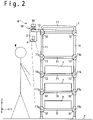
- Fig. 2 is a side view illustrating the configuration of the picking assistant system 10
- Fig. 3 is a side view illustrating the configuration of the picking assistant system on the III-III section illustrated in Fig. 1 .
- the picking assistant system 10 of this embodiment includes an article shelf 1, a projector 2, cameras 3 and 4 and confirmation switches 6.
- the article shelf 1 which is installed on a floor F, holds article boxes 7 accommodating articles P (such as parts and goods) to be picked up at desired positions.
- the article shelf 1 is constituted by pipes 11 coupled with lugs 12.
- the pipes 11 positioned on the front side of the article shelf 1 and extended in the horizontal direction (the X axis direction) may be referred to as front-side horizontal pipes 11a and the pipes 11 positioned on the rear side of the article shelf 1 and extended in the horizontal direction (the X axis direction) may be referred to as rear-side horizontal pipes 11b.
- shelf boards 11c are disposed between the lower three front-side horizontal pipes 11a and the lower three rear-side pipes 11b and the article boxes 7 are placed on the shelf boards 11c.
- An opening 1a from which articles P accommodated in the article boxes 7 are taken out is formed between every adjacent front-side horizontal pipes 11a.
- Screens 5 are hung at each opening 1a of the article shelf 1.
- the screens 5 are used as display regions on which images are projected by the projector 2.
- many screens 5 each elongated in the Z axis direction are hung at the respective openings 1a of the article shelf 1.
- the screens 5 are non-transparent or semi-transparent, and have flexibility. Appropriate fabrics or sheets may be used as the screens 5.
- the projector 2 displays instructions to a worker W on the screens 5.
- the projector 2 displays picking instruction signs which indicate articles to be picked and the number thereof, on the screens 5.
- the projector 2 is hung and held by a support mechanism 8 provided on the upper part of the article shelf 1.
- the projector 2 projects images on the screens 5 obliquely downward from above. This aims at avoiding the movement of the worker W being hindered.
- a short focus projector may be preferably used as the projector 2.
- the cameras 3 and 4 are used as an imaging device which captures images of the article shelf 1. Since the screens 5 are provided at the openings 1a of the article shelf 1, the screens 5 are reflected in the captured images. As described later, the captured images of the article shelf 1 are used to detect the motions of the screens 5. As described later, the picking assistant system 10 of this embodiment is configured to detect an operational error on the basis of the motions of the screens 5 detected from the captured images. A plurality of cameras, in this embodiment, two cameras 3 and 4, are used to capture the images of the article shelf 1. This aims at reducing the dead angle in which the images of the screens 5 cannot be captured. As illustrated in Fig.
- the worker W stands in front of the article shelf 1 when working, and this may cause a dead angle in which the images of the screens 5 cannot be captured if only one camera is provided.
- a plurality of cameras in this embodiment, two cameras 3 and 4, are provided.
- the camera 3 is coupled to the housing of the projector 2 with an arm 17 and the camera 4 is coupled to the housing of the projector 2 with an arm 18.
- Fig. 4 is an enlarged view illustrating the structure of the screens 5.
- the screens 5 are coupled to the front-side horizontal pipes 11a at the upper ends thereof and thereby hung downward from the front-side horizontal pipes 11a.
- a picking instruction sign 30 is displayed on the screens 5.
- the picking instruction sign 30 displayed as a light spot in which number symbols are included. The worker can identify an article box 7 from which articles are to be taken from the picking instruction sign 30, and recognize the number of the article(s) to be taken.
- the picking instruction sign 30 displayed on the screens 5 may include various information other than the number symbols.
- the picking instruction sign 30 may include images of goods or parts, or matters to be attended to in the operation.
- the screens 5 have such a length in the Z axis direction that the worker W inevitably touches a screen 5 when the worker W takes out an article from an article box 7. This is to cause at least one screen 5 to move when the worker W takes out an article.
- markers 31 and 32 arrayed in the vertical direction are disposed on each screen 5.
- the markers 31 and 32 are provided in order to make it easy to detect the motion of each screen 5 from the images captured by the cameras 3 and 4.
- the markers 31 and 32 are formed to have appearances which facilitate the detection of the markers 31 and 32 through image processing.
- the markers 31 and 32 are searched in the captured images and the motions of the markers 31 and 32 are then detected.
- the motions of the markers 31 and 32 in the captured images are detected as the motions of the screens 5. It would be understood that the number and shape of the markers attached to each screen 5 may be variously modified.
- Each confirmation switch 6 is used to inform the picking assistant system 10 that an article stocked in an article box 7 is picked.
- the article boxes 7 are respectively associated with the confirmation switches 6 and placed near the associated confirmation switches 6.
- the worker W presses the confirmation switch 6 associated with the specific article box 7. This allows the picking assistant system 10 to recognize that the article(s) is taken out from the specific article box 7.
- Fig. 5 is a block diagram illustrating the system configuration of the picking assistant system 10 in this embodiment.
- the picking assistant system 10 of this embodiment includes a switch controller 21 and a management terminal 22.
- the switch controller 21 is connected to the respective confirmation switches 6 via a bus 23.
- the switch controller 21 detects pressing of each confirmation switches 6.
- the switch controller 21 transmits to the management terminal 22 a switch press data which indicates that the confirmation switch 6 is pressed.
- the management terminal 22 controls the operation of the entire picking assistant system 10.
- the management terminal 22 includes an interface 24, a processor 25, a display device 26 and an input device 27.
- the interface 24 are used for data communications with the projector 2, the cameras 3, 4 and the switch controller 21.
- the processor 25 performs various data processing for controlling the operation of the entire picking assistant system 10. For example, the processor 25 generates picking instruction data which specify articles to be picked by the worker and the number thereof, and also generates display control data which instruct the projector 2 to display a picking instruction sign at a desired position, on the basis of the generated picking instruction data.
- the processor 25 When the picking assistant system 10 is used in a production line, for example, the processor 25 generates a picking instruction data corresponding to a half-finished product conveyed to the front of the picking assistant system 10 with reference to the switch press data received from the switch controller 21, and further generates a display control data corresponding to the picking instruction data.
- the display control data thus generated is transmitted to the projector 2 and the projector 2 displays a picking instruction sign at a desired position in response to the display control data.
- the processor 25 also detects the motions of the respective screens 5 from the captured images of the screens 5 obtained by the cameras 3 and 4, and detects an operational error on the basis of the detected motions of the screens 5. When the position of a screen 5 which has moved does not match the picking instruction data, for example, the processor 25 determines that an operational error has occurred. When detecting an operational error, the processor 25 asserts an alarm.
- An appropriate visual or acoustic output e.g. an alarm display on the display device 26 and an alarm sound may be used as the alarm.
- the display device 26 and the input device 27 are used as a man-machine interface of the picking assistant system 10.
- the display device 26 is used to display various information for the administrator of the picking assistant system 10.
- the input device 27 is used to input data and instructions into the management terminal 22.
- a general-purpose personal computer or laptop computer may be used as the management terminal 22.
- Fig. 5 illustrates the configuration in which the confirmation switches 6 and the switch controller 21 are connected via the bus 23 to achieve communications therebetween
- the confirmation switches 6 and the switch controller 21 may communicate with each other via wireless communications (e.g. wireless LAN (local area network)).
- wireless communications e.g. wireless LAN (local area network)
- the picking up of articles from the respective article boxes 7 may be detected on the basis of images captured by the cameras 3 and 4, without using the confirmation switches 6.
- the motion of each screen 5 (or the motions of the markers 31 and 32) may detected from the images captured by the cameras 3 and 4 and the article box 7 from which an article is taken from may be detected from the motion of each screen 5 (or the motions of the markers 31 and 32) in the captured images.
- the projector 2 is hung from the upper part of the article shelf 1 with the support mechanism 8.
- the projector 2 tends to suffer from vibrations.
- the picking instruction sign displayed on the screens 5 also vibrates, and this may make it difficult for the worker W to see the picking instruction sign.
- the vibrations tend to be increase, and the vibrations applied to the projector 2 may be a significant issue.
- the support mechanism 8 is configured to provide vibration isolation to reduce vibrations applied to the projector 2.
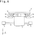
- the support mechanism 8 includes a pair of arms 13, a beam member 14 and a hanger member 15.
- the arms 13 are attached to the upper part of the article shelf 1. As illustrated in Fig. 6 , the respective arms 13 support the ends of the beam member 14 and the hanger member 15 is disposed on the beam member 14. The projector 2 is coupled to the beam member 14 with the hanger member 15 and hung from the beam member 14.
- each vibration isolation device 16 is disposed between each arm 13 and the beam member 14.
- the vibration isolation devices 16 support the beam member 14 so that the arms 13 and the beam member 14 are relatively movable with respect to each other, to thereby achieve vibration isolation.
- each vibration isolation device 16 includes a bottom plate 16a coupled to the corresponding arm 13, a top plate 16b coupled to an end portion of the beam member 14 and an elastic member 16c disposed between the bottom plate 16a and the top plate 16b.
- An anti-vibration pad formed of elastic rubber or the like may be used as the elastic member 16c, for example.
- the projector 2 may include an optical unit 2a accommodating an optical system which projects an image on the screens 5 (e.g. a light source, a light valve (e.g. a liquid crystal panel) and a lens system), an actuator 2b and a vibration sensor 2c.
- the optical unit 2a is supported so that the optical unit 2a is movable with respect to the housing of the projector 2.
- the actuator 2b displaces the optical unit 2a so as to cancel vibrations detected by the vibration sensor 2c.
- the use of the projector 2 thus configured effectively reduces the problem of the vibrations applied to the projector 2.
- a picking instruction data which specifies an article to be next picked by the worker W and the number thereof is generated by the processor 25.
- a picking instruction data which specifies parts to be assembled to the half-assembled finished product and the number thereof is generated.
- a shipper is conveyed to the front of the picking assistant system 10 and a picking instruction data which specifies goods to be put in the shipper and the number thereof is generated.
- a display control data which instructs the projector 2 to display a picking instruction sign at a desired position is generated by the processor 25 on the basis of the picking instruction data, and the generated display control data is transmitted to the projector 2.
- the projector 2 displays the picking instruction sign on the screens 5 in response to the received display control data.
- the picking instruction sign is displayed at the position in front of the article box 7 which accommodates an article to be next picked by the worker W, and this allows the worker W to recognize the article which the worker W should pick up next.
- the picking instruction sign includes the number of the articles the worker W should pick up, and this allows the worker W to recognize the number of the articles the worker W should pick up next.
- the worker W performs the picking work, referring to the picking instruction sign displayed on the screens 5.
- the worker W takes out the articles, the number of which is specified by the picking instruction sign, from the article box 7 positioned near the position at which the picking instruction sign is displayed, and performs the requested work, for example, assembles parts to a half-finished product or puts goods into a shipper.
- the switch controller 21 detects the pressing of the confirmation switch 6 and transmits a switch press data indicating that the confirmation switch 6 is pressed, to the management terminal 22.
- the processor 25 of the management terminal 22 When recognizing the pressing of the confirmation switch 6 from the switch press data, the processor 25 of the management terminal 22 generates a picking instruction data which specifies an article to be next picked by the worker W and the number thereof. Subsequent picking work is achieved in a similar way.
- the picking up of an article from an article box 7 may be detected on the basis of the images captured by the cameras 3 and 4.
- the processor 25 performs image processing on the images captured by the cameras 3 and 4, and when detecting the picking up of an article (s) from a proper article box 7 from the captured images, the processor 25 generates a picking instruction data which specifies articles to be next picked by the worker W and the number thereof.
- the motions of the screens 5 are detected and an operational error of the worker W is detected on the basis of the detected motions of the screens.
- the worker W When taking out an article from an article box 7, the worker W inevitably touches one or more screens 5 and thereby moves the screens 5. Accordingly, it is possible to detect an operational error by detecting the motions of the screens 5.
- image processing is performed on the images of the screens 5 captured by the cameras 3 and 4 by the processor 25, to thereby detect the motions of the screens 5.
- two markers 31 and 32 are attached to each screen 5 and the motion of each screen 5 is detected from the captured images.
- the markers 31 and 32 are searched in the captured images and the motions of the markers 31 and 32 are detected as the motions of the screens 5.
- the processor 25 determines that an operational error has occurred and asserts an alarm. For example, when detecting a motion of a screen 5 at a position distant from the article box 7 accommodating an article specified by the picking instruction data to be picked, the processor 25 determines that an operational error has occurred and asserts an alarm.
- the alarm may be generated in the form of lighting of an alarm lamp or generation of an alarm sound.
- the motions of the screens 5 may be detected with other appropriate measures.
- the motions of the screens 5 may be detected by using sensors which mechanically detects the motions of the screens 5; however, the method of this embodiment, in which the motions of the screens 5 are detected from the captured images, is preferable in that the motions of a large number of screens 5 can be detected with simple configuration.
- replacement of a vacant article box 7 is not detected as an operational error, even if the motions of the screens 5 do not match the picking instruction data.
- the replacement of a vacant article box 7 is performed in the normal operation, and it is unpreferable to assert an alarm for such operation.
- the picking assistant system 10 is configured to detect the motions of the article boxes 7.
- an operational error is detected on the basis of the motions of the article boxes 7, in addition to the motions of the screens 5. For example, even if the motion of a screen 5 does not match the picking instruction data, this motion is not detected as an operational error when the motion of an article box 7 is detected near the screen 5 which has moved.
- the motions of the article boxes 7 are detected by performing image processing on the images captured by the cameras 3 and 4.
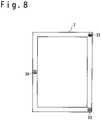
- markers are attached to the respective article boxes 7 as illustrated in Fig. 8 .
- Fig. 8 for example, three markers 33 to 35 are attached to each article box 7.
- the markers 33 to 35 are attached at such positions of each article box 7 that the cameras 3 and 4 can easily capture an image of the markers 33 to 35. Since the cameras 3 and 4 captures an image of the article box 7 from above as illustrated in Fig. 9 , it is preferable that the markers 33 to 35 are attached to the upper face of the side wall of the article box 7. It is also preferable that the markers 33 to 35 are formed to have appearances which facilitate the detection of the markers 33 to 35 through image processing.
- the processor 25 searches the markers 33 to 35 in the captured images in the image processing of the captured images, and when having found any of the markers 33 to 35, detects the motion of the marker(s) found.
- the motion of the marker(s) in the captured images is detected as the motion of an article box 7.
- the picking assistant system 10 of the embodiment which is configured to detect operational errors on the basis of the motions of the screens 5, effectively reduces operational errors.
- the approach of this embodiment, in which operational errors are detected on the basis of the motions of the screens 5, is suitable for the configuration in which a projector is used as a display device.
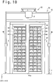
- Fig. 10 is a front view illustrating the configuration of a picking assistant system 10A in an example serving to explain aspects of the invention
- Fig. 11 is a block diagram illustrating the configuration of the picking assistant system 10A.
- the configuration of the picking assistant system 10A of the example is similar to that of the picking assistant system 10 of the embodiment.
- the confirmation switches 6 and the switch controller 21 are not provided for the picking assistant system 10A of the example.
- a detailed description is given of the picking assistant system 10A of the example.
- the picking assistant system 10A of the example includes an article shelf 41, a support frame 42, a projector 2 and cameras 3 and 4.
- the article shelf 41 and the support frame 42 are installed on the floor F.
- the support frame 42 supports the projector 2 and the cameras 3 and 4.
- the article shelf 41 is configured to be suitable for stocking relatively small articles. More specifically, the article shelf 41 includes a cabinet 43 and drawer cases 44, which are used as article boxes accommodating articles. In the configuration illustrated in Fig. 10 , drawer cases 44 arrayed in three columns and 14 rows are provided in the left half of the article shelf 41 and drawer cases 44 arrayed in three columns and 14 rows are provided in the right half.
- the cabinet 43 holds the drawer cases 44 so that the drawer cases 44 can be drawn and retracted (that is, the drawer cases 44 are movable in the +Y and -Y directions).
- the number and arrangement of the drawer cases 44 may be variously modified.
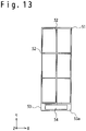
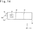
- Figs. 12 , 13 and 14 are a perspective view, upper view and side view, respectively, which illustrate the structure of a drawer case 44.
- the drawer case 44 includes a box member 51 which is open at the upper side, and the inner space of the box member 51 is partitioned into a plurality of partitions (in this example, six partitions) with partition plates 52 as illustrated in Fig. 13 .
- a grip portion 53 is attached to the front face 51a of the box member 51. A worker can draw the drawer case 44 by gripping the grip portion 53.
- the grip portion 53 has a slanting face 53a and an unfigured label 54 is stuck on the slanting face 53a.
- the label 54 of each drawer case 44 is used as a display region on which an image is projected by the projector 2.
- Markers 55 are provided on both of the side faces 51b (that is, the faces facing in the +X and -X directions) of the box member 51.
- the markers 55 are provided to facilitate detection of the motion of each drawer case 44 from images captured by the cameras 3 and 4.
- the markers 55 are formed to have appearances which facilitate detection thereof through image processing. When detecting the motion of each drawer case 44 from the captured images, markers 55 are searched in the captured images and the motions of the markers 55 are further detected. The motions of the markers 55 in the captured images are detected as the motion of the corresponding drawer case 44. It would be understood that the number and shape of the markers 55 attached to each drawer case 44 may be variously modified.
- the projector 2 displays instructions to the worker W on the label 54 provided on each drawer case 44.
- the projector 2 displays a picking instruction sign which specifies an article to be picked and the number thereof, on the label 54 of the drawer case 44 in which the article to be picked are stocked.
- the projector 2 may display a desired sign at a desired position of the article shelf 41, other than the position of on the label 54 provided on each drawer case 44.
- the projector 2 may display a sign illustrating instructions to the worker and matters to be attended to in the operation.
- the projector 2 is supported and hung by a support mechanism 45 provided on the upper part of the support frame 42 and the projector 2 displays a picking instruction sign on the label 54 of each drawer case 44 by projecting an image obliquely downward from above.
- the support mechanism 45 may be configured to provide vibration isolation as is the case with the support mechanism 8 in the embodiment.
- the projector 2 itself may be configured to cancel vibrations applied to the projector 2 as illustrated in Fig. 7 . The use of the projector 2 thus configured effectively reduces the problem of the vibrations applied to the projector 2.
- the cameras 3 and 4 are used as an imaging device which captures images of the article shelf 41. As described later, the captured images of the article shelf 41 are used to detect the motions of the drawer cases 44 in this example.
- the cameras 3 and 4 are attached to vertical poles 46 of the support frame 42. In this example, the cameras 3 and 4 are arranged to capture images of the article shelf 41 in the horizontal directions. In detail, the camera 3 is positioned on the left of the article shelf 41 (that is, in the +X direction with respect to the article shelf 41) and the camera 4 is positioned on the right of the article shelf 41 (that is, in the -X direction with respect to the article shelf 41).
- This aims at capturing images of the markers 55 provided on both of the side faces 51b of the box member 51 of each drawer case 44. As described later, the markers 55 provided on both of the side faces 51b of each drawer case 44 are used to detect the motion of each drawer case 44.
- the picking assistant system 10A of this example includes a management terminal 22 which controls the operation of the entire picking assistant system 10A.
- the management terminal 22 includes an interface 24, a processor 25, a display device 26 and an input device 27.
- the processor 25 performs various data processing for controlling the operation of the entire picking assistant system 10A.
- the processor 25 generates a picking instruction data which specifies articles to be picked by the worker and the number thereof, and also generates a display control data which instructs the projector 2 to display a picking instruction sign on the label 54 of a desired one(s) of the drawer cases 44, on the basis of the generated picking instruction data.
- the display control data thus generated is transmitted to the projector 2, and the projector 2 displays a picking instruction sign on the label 54 of the desired one(s) of the drawer cases 44 in response to the display control data.
- the processor 25 may control the projector 2 to display a desired sign at a desired position of the article shelf 41, other than the positions on the labels 54 of the drawer cases 44.
- the processor 25 also detects the motions of the respective drawer cases 44 from the captured images of the article shelf 41 obtained by the cameras 3 and 4, and detects an operational error on the basis of the detected motions of the drawer cases 44. When the position of a drawer case 44 which has moved does not match the picking instruction data, for example, the processor 25 determines that an operational error has occurred. When detecting an operational error, the processor 25 asserts an alarm. An appropriate visual or acoustic output (e.g. an alarm display on the display device 26 and an alarm sound) may be used as the alarm.
- An appropriate visual or acoustic output e.g. an alarm display on the display device 26 and an alarm sound
- a picking instruction data which specifies an article to be next picked by the worker W and the number thereof is generated by the processor 25.
- a display control data which instructs the projector 2 to display a picking instruction sign on the label 54 of the drawer case 44 which accommodates the article to be next picked is generated by the processor 25 on the basis of the picking instruction data, and the generated display control data is transmitted to the projector 2.
- the projector 2 displays the picking instruction sign on the label 54 of the relevant drawer case 44 in response to the received display control data.
- the picking instruction sign is displayed on the label 54 of the drawer case 44 which accommodates the article to be next picked by the worker W, and this allows the worker to easily recognize the article which the worker should pick up next.
- the picking instruction sign includes the number of the articles the worker should pick up, and this allows the worker to recognize the number of the articles the worker should pick up next.
- the worker performs the picking work, referring to the picking instruction sign displayed on the label 54 of the drawer case 44.
- the worker W takes out the article(s), the number of which is specified by the picking instruction sign, from the drawer case 44 on which the picking instruction sign is displayed, and performs the requested work, for example, assembles parts to a half-finished product or puts goods into a shipper.
- the processor 25 detects the motion of the drawer case 44 from the captured images. This allows the processor 25 to detect whether the article is taken out from a proper drawer case 44 from the motion of the drawer case 44.
- the markers 55 are attached to each drawer case 44, and the markers 55 are searched in the captured images in the image processing for detecting the motion of each drawer case 44 from the captured images. The motions of the markers 55 are detected as the motion of each drawer case 44.
- the processor 25 When detecting the picking up of an article(s) from a proper drawer case 44 from the captured images, the processor 25 generates a picking instruction data which specifies articles to be next picked by the worker W and the number thereof.
- the processor 25 determines that an operation error has occurred.
- the processor 25 determines that an operational error has occurred and asserts an alarm.
- the processor 25 determines that an operational error has occurred and asserts an alarm.
- the alarm may be generated in the form of lighting of an alarm lamp or generation of an alarm sound.
- the picking assistant system 10A of the example which is configured to detect operational errors on the basis of the motions of the drawer cases 44, effectively reduces operational errors.
- the approach of this example, in which operational errors are detected on the basis of the motions of the drawer cases 44, is suitable for the configuration in which a projector is used as a display device.
Applications Claiming Priority (1)
| Application Number | Priority Date | Filing Date | Title |
|---|---|---|---|
| PCT/JP2016/076868 WO2018047355A1 (ja) | 2016-09-12 | 2016-09-12 | ピッキング支援装置 |
Publications (3)
| Publication Number | Publication Date |
|---|---|
| EP3533729A1 EP3533729A1 (en) | 2019-09-04 |
| EP3533729A4 EP3533729A4 (en) | 2020-05-13 |
| EP3533729B1 true EP3533729B1 (en) | 2022-10-26 |
Family
ID=61561538
Family Applications (1)
| Application Number | Title | Priority Date | Filing Date |
|---|---|---|---|
| EP16905694.2A Active EP3533729B1 (en) | 2016-09-12 | 2016-09-12 | Picking assistance device |
Country Status (6)
| Country | Link |
|---|---|
| US (1) | US10504199B2 (ja) |
| EP (1) | EP3533729B1 (ja) |
| JP (1) | JP6496082B2 (ja) |
| CN (1) | CN108137230B (ja) |
| TW (1) | TWI641545B (ja) |
| WO (1) | WO2018047355A1 (ja) |
Families Citing this family (40)
| Publication number | Priority date | Publication date | Assignee | Title |
|---|---|---|---|---|
| US9139363B2 (en) | 2013-03-15 | 2015-09-22 | John Lert | Automated system for transporting payloads |
| US10435241B2 (en) | 2015-06-02 | 2019-10-08 | Alert Innovation Inc. | Storage and retrieval system |
| US11142398B2 (en) | 2015-06-02 | 2021-10-12 | Alert Innovation Inc. | Order fulfillment system |
| US11203486B2 (en) | 2015-06-02 | 2021-12-21 | Alert Innovation Inc. | Order fulfillment system |
| US10346793B2 (en) * | 2016-01-29 | 2019-07-09 | Walmart Apollo, Llc | Systems and methods for order filling |
| AU2017362508A1 (en) | 2016-11-17 | 2019-06-20 | Walmart Apollo, Llc | Automated-service retail system and method |
| EP3549077A1 (en) | 2016-11-29 | 2019-10-09 | Alert Innovation Inc. | Automated retail supply chain and inventory management system |
| MX2019008112A (es) | 2017-01-10 | 2019-10-24 | Alert Innovation Inc | Tienda automatizada con robots moviles intercambiables. |
| US10657580B2 (en) | 2017-01-27 | 2020-05-19 | Walmart Apollo, Llc | System for improving in-store picking performance and experience by optimizing tote-fill and order batching of items in retail store and method of using same |
| US10445691B2 (en) * | 2017-01-27 | 2019-10-15 | Walmart Apollo, Llc | System for improving order batching using location information of items in retail store and method of using same |
| US10572932B2 (en) | 2017-01-27 | 2020-02-25 | Walmart Apollo, Llc | System for providing optimal shopping routes in retail store and method of using same |
| EP4044083B1 (en) * | 2017-02-24 | 2023-09-13 | Walmart Apollo, Llc | Inventory management system and method |
| US10825076B2 (en) | 2017-04-17 | 2020-11-03 | Walmart Apollo Llc | Systems to fulfill a picked sales order and related methods therefor |
| US10846645B2 (en) | 2017-04-28 | 2020-11-24 | Walmart Apollo, Llc | Systems and methods for real-time order delay management |
| US10810542B2 (en) | 2017-05-11 | 2020-10-20 | Walmart Apollo, Llc | Systems and methods for fulfilment design and optimization |
| US11126953B2 (en) | 2017-06-14 | 2021-09-21 | Walmart Apollo, Llc | Systems and methods for automatically invoking a delivery request for an in-progress order |
| US11126954B2 (en) | 2017-06-28 | 2021-09-21 | Walmart Apollo, Llc | Systems and methods for automatically requesting delivery drivers for online orders |
| US10909612B2 (en) | 2017-07-13 | 2021-02-02 | Walmart Apollo Llc | Systems and methods for determining an order collection start time |
| US11074547B2 (en) * | 2018-04-20 | 2021-07-27 | Walmart Apollo, Llc | Systems and methods for dual optimization of pick walk and tote fill rates for order picking |
| JP6915590B2 (ja) * | 2018-06-06 | 2021-08-04 | 株式会社ダイフク | 物品搬送車 |
| US11908307B2 (en) | 2018-06-07 | 2024-02-20 | William J. Hoofe, IV | Security system |
| JP6535789B1 (ja) * | 2018-06-18 | 2019-06-26 | 日本たばこ産業株式会社 | たばこ什器 |
| WO2019244800A1 (ja) * | 2018-06-18 | 2019-12-26 | 日本たばこ産業株式会社 | たばこ什器 |
| JP6841270B2 (ja) * | 2018-06-22 | 2021-03-10 | 株式会社ダイフク | 物品搬送車 |
| US10769587B2 (en) * | 2018-07-02 | 2020-09-08 | Walmart Apollo, Llc | Systems and methods of storing and retrieving retail store product inventory |
| JP6674515B2 (ja) * | 2018-09-03 | 2020-04-01 | 三菱ロジスネクスト株式会社 | 判定装置および判定方法 |
| JP6656328B1 (ja) * | 2018-09-10 | 2020-03-04 | 株式会社アイオイ・システム | 作業支援装置 |
| US10783762B1 (en) * | 2019-10-25 | 2020-09-22 | 7-Eleven, Inc. | Custom rack for scalable position tracking system |
| US11030756B2 (en) | 2018-10-26 | 2021-06-08 | 7-Eleven, Inc. | System and method for position tracking using edge computing |
| JP6678790B1 (ja) * | 2019-02-21 | 2020-04-08 | 株式会社アイオイ・システム | 作業支援装置 |
| JP7243373B2 (ja) * | 2019-03-27 | 2023-03-22 | 凸版印刷株式会社 | 作業支援システム |
| CN110659862B (zh) * | 2019-09-26 | 2023-04-07 | 深圳市凯东源现代物流股份有限公司 | 一种仓储信息处理方法和系统 |
| US11587243B2 (en) | 2019-10-25 | 2023-02-21 | 7-Eleven, Inc. | System and method for position tracking using edge computing |
| US11501454B2 (en) | 2019-10-25 | 2022-11-15 | 7-Eleven, Inc. | Mapping wireless weight sensor array for item detection and identification |
| US11450011B2 (en) | 2019-10-25 | 2022-09-20 | 7-Eleven, Inc. | Adaptive item counting algorithm for weight sensor using sensitivity analysis of the weight sensor |
| US11657347B2 (en) | 2020-01-31 | 2023-05-23 | Walmart Apollo, Llc | Systems and methods for optimization of pick walks |
| US11868958B2 (en) * | 2020-01-31 | 2024-01-09 | Walmart Apollo, Llc | Systems and methods for optimization of pick walks |
| CN112085934A (zh) * | 2020-08-20 | 2020-12-15 | 上海姜歌机器人有限公司 | 一种针对拣货机器人的拣货提示方法及拣货机器人 |
| CN113734684A (zh) * | 2021-09-14 | 2021-12-03 | 广州丰沃信息科技有限公司 | 一种智能投影辅助拣选工作站及其拣选方法 |
| WO2023067857A1 (ja) | 2021-10-20 | 2023-04-27 | 株式会社アイオイ・システム | 作業支援装置、及び非一時記憶媒体 |
Family Cites Families (26)
| Publication number | Priority date | Publication date | Assignee | Title |
|---|---|---|---|---|
| JPS5844011A (ja) | 1981-09-11 | 1983-03-14 | 新田 豊顕 | 自動茹麺機 |
| JPS63153843A (ja) | 1986-12-17 | 1988-06-27 | Matsushita Electronics Corp | 樹脂封止型半導体装置のマ−キング方法 |
| JPH0546682Y2 (ja) * | 1987-03-28 | 1993-12-07 | ||
| DE19843902A1 (de) * | 1997-09-26 | 1999-04-01 | Denso Corp | Bildinformations-Anzeigesystem und Hologramm-Anzeigevorrichtung |
| US7084738B2 (en) | 2000-12-11 | 2006-08-01 | Asap Automation, Llc | Inventory system with image display |
| JP4074222B2 (ja) | 2003-06-09 | 2008-04-09 | 株式会社アイオイ・システム | ピッキング支援装置 |
| JP4194497B2 (ja) * | 2004-01-20 | 2008-12-10 | キヤノン株式会社 | 物品収納装置及びその物品収納方法、並びに制御プログラム |
| JP2006321590A (ja) | 2005-05-17 | 2006-11-30 | Aioi Systems Co Ltd | ピッキング支援装置 |
| US8073562B2 (en) * | 2007-01-26 | 2011-12-06 | Innovative Picking Technologies, Inc. | Picking system with pick verification |
| JP2008222386A (ja) * | 2007-03-13 | 2008-09-25 | Omron Corp | 作業支援装置 |
| WO2009058384A2 (en) * | 2007-10-30 | 2009-05-07 | Paceco Corp | Methods and apparatus processing container images and/or identifying codes for front end loaders or container handlers servicing rail cars |
| CN101710080B (zh) * | 2009-12-01 | 2011-04-06 | 湖南大学 | 一种基于机器视觉的码垛玻璃瓶检测方法与搬运机 |
| JP5556193B2 (ja) | 2010-01-26 | 2014-07-23 | セイコーエプソン株式会社 | 投写装置および投写装置の画像ブレ防止制御方法 |
| JP6127502B2 (ja) * | 2012-06-26 | 2017-05-17 | 株式会社豊田自動織機 | 作業支援装置 |
| JP2014070796A (ja) * | 2012-09-28 | 2014-04-21 | Sharp Corp | 庫内撮影装置および冷蔵庫 |
| US9663293B2 (en) * | 2012-10-08 | 2017-05-30 | Amazon Technologies, Inc. | Replenishing a retail facility |
| US9473747B2 (en) | 2013-07-25 | 2016-10-18 | Ncr Corporation | Whole store scanner |
| WO2015146805A1 (ja) * | 2014-03-25 | 2015-10-01 | コニカミノルタ株式会社 | 投光装置、及び、投光方法 |
| US9120621B1 (en) * | 2014-03-25 | 2015-09-01 | Amazon Technologies, Inc. | Verifying bin content in an automated materials handling facility |
| JP5844011B1 (ja) * | 2014-04-21 | 2016-01-13 | 株式会社 エニイワイヤ | 組立用物品管理システム |
| WO2016002622A1 (ja) * | 2014-06-30 | 2016-01-07 | 株式会社日立国際電気 | 情報表示システム |
| US9489655B1 (en) * | 2014-08-25 | 2016-11-08 | Amazon Technologies, Inc. | Distinguishing RFID tags using motion data |
| KR20160028287A (ko) * | 2014-09-03 | 2016-03-11 | 한국항공대학교산학협력단 | 자동화물 시스템의 셔틀유닛 충돌 방지 방법 |
| US9996818B1 (en) * | 2014-12-19 | 2018-06-12 | Amazon Technologies, Inc. | Counting inventory items using image analysis and depth information |
| JP6411204B2 (ja) * | 2014-12-22 | 2018-10-24 | トーヨーカネツソリューションズ株式会社 | プロジェクタ利用ピッキング装置 |
| CN104528244B (zh) * | 2014-12-22 | 2016-06-22 | 北京物资学院 | 一种光学物流拣选导引方法和系统 |
-
2016
- 2016-09-12 EP EP16905694.2A patent/EP3533729B1/en active Active
- 2016-09-12 JP JP2018508263A patent/JP6496082B2/ja active Active
- 2016-09-12 US US15/740,984 patent/US10504199B2/en active Active
- 2016-09-12 WO PCT/JP2016/076868 patent/WO2018047355A1/ja active Application Filing
- 2016-09-12 CN CN201680023215.2A patent/CN108137230B/zh active Active
-
2017
- 2017-09-08 TW TW106130793A patent/TWI641545B/zh active
Also Published As
| Publication number | Publication date |
|---|---|
| JP6496082B2 (ja) | 2019-04-03 |
| US20180342031A1 (en) | 2018-11-29 |
| CN108137230A (zh) | 2018-06-08 |
| EP3533729A1 (en) | 2019-09-04 |
| WO2018047355A1 (ja) | 2018-03-15 |
| EP3533729A4 (en) | 2020-05-13 |
| US10504199B2 (en) | 2019-12-10 |
| JPWO2018047355A1 (ja) | 2018-09-06 |
| TWI641545B (zh) | 2018-11-21 |
| TW201811636A (zh) | 2018-04-01 |
| CN108137230B (zh) | 2020-07-03 |
Similar Documents
| Publication | Publication Date | Title |
|---|---|---|
| EP3533729B1 (en) | Picking assistance device | |
| CN202676614U (zh) | 产品外观自动检测系统 | |
| US8162486B2 (en) | Remote set-up and calibration of an interactive system | |
| US20210264210A1 (en) | Learning data collection device, learning data collection system, and learning data collection method | |
| JP2007050932A (ja) | 包装機械 | |
| CN106056774B (zh) | 基于过程保护的证卡领取自助服务设备及证卡领取方法 | |
| US20170263016A1 (en) | Computer-readable storage medium storing management program, management apparatus, and management method | |
| CN109715307A (zh) | 具有工作区图像捕获设备的弯曲机以及用于表示工作区的方法 | |
| WO2016053320A1 (en) | Gesture based manipulation of three-dimensional images | |
| JP2015089586A (ja) | 作業順守支援装置 | |
| JP6902369B2 (ja) | 提示装置、提示方法およびプログラム、ならびに作業システム | |
| JP6656328B1 (ja) | 作業支援装置 | |
| US20060158616A1 (en) | Apparatus and method for interacting with a subject in an environment | |
| US20180007341A1 (en) | Technologies for automated projector placement for projected computing interactions | |
| JP2011101915A (ja) | ロボットシステム | |
| JP2011110627A (ja) | ロボット制御方法、ロボット制御プログラムおよびロボット制御方法に用いられるティーチングペンダント | |
| CN104354935A (zh) | 用于透明包装材料上拉线缺陷检测装置 | |
| US20060158521A1 (en) | Mechanical and thermal aspects of an enclosure for interactive system components and the like | |
| US20200241721A1 (en) | Interactive display apparatus and method | |
| EP3451116A1 (en) | Data processing apparatus | |
| WO2019207816A1 (ja) | シミュレーション装置およびシミュレーション方法 | |
| KR102642975B1 (ko) | 작업 가이드 장치를 통한 작업 가이드 방법 및 시스템 | |
| CN209111091U (zh) | 机器人 | |
| KR102486103B1 (ko) | 공정 중 이동 간 틸팅기능을 제공하는 워크스테이션 | |
| KR102486117B1 (ko) | 작업능률 향상을 위한 틸팅기능을 제공하는 워크스테이션 |
Legal Events
| Date | Code | Title | Description |
|---|---|---|---|
| STAA | Information on the status of an ep patent application or granted ep patent |
Free format text: STATUS: UNKNOWN |
|
| STAA | Information on the status of an ep patent application or granted ep patent |
Free format text: STATUS: THE INTERNATIONAL PUBLICATION HAS BEEN MADE |
|
| PUAI | Public reference made under article 153(3) epc to a published international application that has entered the european phase |
Free format text: ORIGINAL CODE: 0009012 |
|
| STAA | Information on the status of an ep patent application or granted ep patent |
Free format text: STATUS: REQUEST FOR EXAMINATION WAS MADE |
|
| 17P | Request for examination filed |
Effective date: 20171229 |
|
| AK | Designated contracting states |
Kind code of ref document: A1 Designated state(s): AL AT BE BG CH CY CZ DE DK EE ES FI FR GB GR HR HU IE IS IT LI LT LU LV MC MK MT NL NO PL PT RO RS SE SI SK SM TR |
|
| AX | Request for extension of the european patent |
Extension state: BA ME |
|
| DAV | Request for validation of the european patent (deleted) | ||
| DAX | Request for extension of the european patent (deleted) | ||
| A4 | Supplementary search report drawn up and despatched |
Effective date: 20200415 |
|
| RIC1 | Information provided on ipc code assigned before grant |
Ipc: G06Q 10/08 20120101ALI20200407BHEP Ipc: B65G 1/137 20060101AFI20200407BHEP Ipc: G06Q 50/28 20120101ALI20200407BHEP Ipc: H04N 9/31 20060101ALI20200407BHEP |
|
| STAA | Information on the status of an ep patent application or granted ep patent |
Free format text: STATUS: EXAMINATION IS IN PROGRESS |
|
| STAA | Information on the status of an ep patent application or granted ep patent |
Free format text: STATUS: EXAMINATION IS IN PROGRESS |
|
| 17Q | First examination report despatched |
Effective date: 20201120 |
|
| STAA | Information on the status of an ep patent application or granted ep patent |
Free format text: STATUS: EXAMINATION IS IN PROGRESS |
|
| GRAP | Despatch of communication of intention to grant a patent |
Free format text: ORIGINAL CODE: EPIDOSNIGR1 |
|
| STAA | Information on the status of an ep patent application or granted ep patent |
Free format text: STATUS: GRANT OF PATENT IS INTENDED |
|
| INTG | Intention to grant announced |
Effective date: 20220617 |
|
| GRAS | Grant fee paid |
Free format text: ORIGINAL CODE: EPIDOSNIGR3 |
|
| GRAA | (expected) grant |
Free format text: ORIGINAL CODE: 0009210 |
|
| STAA | Information on the status of an ep patent application or granted ep patent |
Free format text: STATUS: THE PATENT HAS BEEN GRANTED |
|
| AK | Designated contracting states |
Kind code of ref document: B1 Designated state(s): AL AT BE BG CH CY CZ DE DK EE ES FI FR GB GR HR HU IE IS IT LI LT LU LV MC MK MT NL NO PL PT RO RS SE SI SK SM TR |
|
| REG | Reference to a national code |
Ref country code: GB Ref legal event code: FG4D |
|
| REG | Reference to a national code |
Ref country code: CH Ref legal event code: EP |
|
| REG | Reference to a national code |
Ref country code: AT Ref legal event code: REF Ref document number: 1526913 Country of ref document: AT Kind code of ref document: T Effective date: 20221115 |
|
| REG | Reference to a national code |
Ref country code: DE Ref legal event code: R096 Ref document number: 602016075980 Country of ref document: DE |
|
| REG | Reference to a national code |
Ref country code: IE Ref legal event code: FG4D |
|
| REG | Reference to a national code |
Ref country code: LT Ref legal event code: MG9D |
|
| REG | Reference to a national code |
Ref country code: NL Ref legal event code: MP Effective date: 20221026 |
|
| REG | Reference to a national code |
Ref country code: AT Ref legal event code: MK05 Ref document number: 1526913 Country of ref document: AT Kind code of ref document: T Effective date: 20221026 |
|
| PG25 | Lapsed in a contracting state [announced via postgrant information from national office to epo] |
Ref country code: NL Free format text: LAPSE BECAUSE OF FAILURE TO SUBMIT A TRANSLATION OF THE DESCRIPTION OR TO PAY THE FEE WITHIN THE PRESCRIBED TIME-LIMIT Effective date: 20221026 |
|
| PG25 | Lapsed in a contracting state [announced via postgrant information from national office to epo] |
Ref country code: SE Free format text: LAPSE BECAUSE OF FAILURE TO SUBMIT A TRANSLATION OF THE DESCRIPTION OR TO PAY THE FEE WITHIN THE PRESCRIBED TIME-LIMIT Effective date: 20221026 Ref country code: PT Free format text: LAPSE BECAUSE OF FAILURE TO SUBMIT A TRANSLATION OF THE DESCRIPTION OR TO PAY THE FEE WITHIN THE PRESCRIBED TIME-LIMIT Effective date: 20230227 Ref country code: NO Free format text: LAPSE BECAUSE OF FAILURE TO SUBMIT A TRANSLATION OF THE DESCRIPTION OR TO PAY THE FEE WITHIN THE PRESCRIBED TIME-LIMIT Effective date: 20230126 Ref country code: LT Free format text: LAPSE BECAUSE OF FAILURE TO SUBMIT A TRANSLATION OF THE DESCRIPTION OR TO PAY THE FEE WITHIN THE PRESCRIBED TIME-LIMIT Effective date: 20221026 Ref country code: FI Free format text: LAPSE BECAUSE OF FAILURE TO SUBMIT A TRANSLATION OF THE DESCRIPTION OR TO PAY THE FEE WITHIN THE PRESCRIBED TIME-LIMIT Effective date: 20221026 Ref country code: ES Free format text: LAPSE BECAUSE OF FAILURE TO SUBMIT A TRANSLATION OF THE DESCRIPTION OR TO PAY THE FEE WITHIN THE PRESCRIBED TIME-LIMIT Effective date: 20221026 Ref country code: AT Free format text: LAPSE BECAUSE OF FAILURE TO SUBMIT A TRANSLATION OF THE DESCRIPTION OR TO PAY THE FEE WITHIN THE PRESCRIBED TIME-LIMIT Effective date: 20221026 |
|
| PG25 | Lapsed in a contracting state [announced via postgrant information from national office to epo] |
Ref country code: RS Free format text: LAPSE BECAUSE OF FAILURE TO SUBMIT A TRANSLATION OF THE DESCRIPTION OR TO PAY THE FEE WITHIN THE PRESCRIBED TIME-LIMIT Effective date: 20221026 Ref country code: PL Free format text: LAPSE BECAUSE OF FAILURE TO SUBMIT A TRANSLATION OF THE DESCRIPTION OR TO PAY THE FEE WITHIN THE PRESCRIBED TIME-LIMIT Effective date: 20221026 Ref country code: LV Free format text: LAPSE BECAUSE OF FAILURE TO SUBMIT A TRANSLATION OF THE DESCRIPTION OR TO PAY THE FEE WITHIN THE PRESCRIBED TIME-LIMIT Effective date: 20221026 Ref country code: IS Free format text: LAPSE BECAUSE OF FAILURE TO SUBMIT A TRANSLATION OF THE DESCRIPTION OR TO PAY THE FEE WITHIN THE PRESCRIBED TIME-LIMIT Effective date: 20230226 Ref country code: HR Free format text: LAPSE BECAUSE OF FAILURE TO SUBMIT A TRANSLATION OF THE DESCRIPTION OR TO PAY THE FEE WITHIN THE PRESCRIBED TIME-LIMIT Effective date: 20221026 Ref country code: GR Free format text: LAPSE BECAUSE OF FAILURE TO SUBMIT A TRANSLATION OF THE DESCRIPTION OR TO PAY THE FEE WITHIN THE PRESCRIBED TIME-LIMIT Effective date: 20230127 |
|
| REG | Reference to a national code |
Ref country code: DE Ref legal event code: R097 Ref document number: 602016075980 Country of ref document: DE |
|
| PG25 | Lapsed in a contracting state [announced via postgrant information from national office to epo] |
Ref country code: SM Free format text: LAPSE BECAUSE OF FAILURE TO SUBMIT A TRANSLATION OF THE DESCRIPTION OR TO PAY THE FEE WITHIN THE PRESCRIBED TIME-LIMIT Effective date: 20221026 Ref country code: RO Free format text: LAPSE BECAUSE OF FAILURE TO SUBMIT A TRANSLATION OF THE DESCRIPTION OR TO PAY THE FEE WITHIN THE PRESCRIBED TIME-LIMIT Effective date: 20221026 Ref country code: EE Free format text: LAPSE BECAUSE OF FAILURE TO SUBMIT A TRANSLATION OF THE DESCRIPTION OR TO PAY THE FEE WITHIN THE PRESCRIBED TIME-LIMIT Effective date: 20221026 Ref country code: DK Free format text: LAPSE BECAUSE OF FAILURE TO SUBMIT A TRANSLATION OF THE DESCRIPTION OR TO PAY THE FEE WITHIN THE PRESCRIBED TIME-LIMIT Effective date: 20221026 Ref country code: CZ Free format text: LAPSE BECAUSE OF FAILURE TO SUBMIT A TRANSLATION OF THE DESCRIPTION OR TO PAY THE FEE WITHIN THE PRESCRIBED TIME-LIMIT Effective date: 20221026 |
|
| PG25 | Lapsed in a contracting state [announced via postgrant information from national office to epo] |
Ref country code: SK Free format text: LAPSE BECAUSE OF FAILURE TO SUBMIT A TRANSLATION OF THE DESCRIPTION OR TO PAY THE FEE WITHIN THE PRESCRIBED TIME-LIMIT Effective date: 20221026 Ref country code: AL Free format text: LAPSE BECAUSE OF FAILURE TO SUBMIT A TRANSLATION OF THE DESCRIPTION OR TO PAY THE FEE WITHIN THE PRESCRIBED TIME-LIMIT Effective date: 20221026 |
|
| PLBE | No opposition filed within time limit |
Free format text: ORIGINAL CODE: 0009261 |
|
| STAA | Information on the status of an ep patent application or granted ep patent |
Free format text: STATUS: NO OPPOSITION FILED WITHIN TIME LIMIT |
|
| 26N | No opposition filed |
Effective date: 20230727 |
|
| PG25 | Lapsed in a contracting state [announced via postgrant information from national office to epo] |
Ref country code: SI Free format text: LAPSE BECAUSE OF FAILURE TO SUBMIT A TRANSLATION OF THE DESCRIPTION OR TO PAY THE FEE WITHIN THE PRESCRIBED TIME-LIMIT Effective date: 20221026 |
|
| PGFP | Annual fee paid to national office [announced via postgrant information from national office to epo] |
Ref country code: DE Payment date: 20230802 Year of fee payment: 8 |
|
| REG | Reference to a national code |
Ref country code: CH Ref legal event code: PL |