EP3532729B2 - Horizontal geteilte schraubenspindelpumpe - Google Patents
Horizontal geteilte schraubenspindelpumpe Download PDFInfo
- Publication number
- EP3532729B2 EP3532729B2 EP17801607.7A EP17801607A EP3532729B2 EP 3532729 B2 EP3532729 B2 EP 3532729B2 EP 17801607 A EP17801607 A EP 17801607A EP 3532729 B2 EP3532729 B2 EP 3532729B2
- Authority
- EP
- European Patent Office
- Prior art keywords
- housing part
- screw
- screw pump
- housing
- pump
- Prior art date
- Legal status (The legal status is an assumption and is not a legal conclusion. Google has not performed a legal analysis and makes no representation as to the accuracy of the status listed.)
- Active
Links
Images

Classifications
-
- F—MECHANICAL ENGINEERING; LIGHTING; HEATING; WEAPONS; BLASTING
- F04—POSITIVE - DISPLACEMENT MACHINES FOR LIQUIDS; PUMPS FOR LIQUIDS OR ELASTIC FLUIDS
- F04C—ROTARY-PISTON, OR OSCILLATING-PISTON, POSITIVE-DISPLACEMENT MACHINES FOR LIQUIDS; ROTARY-PISTON, OR OSCILLATING-PISTON, POSITIVE-DISPLACEMENT PUMPS
- F04C2/00—Rotary-piston machines or pumps
- F04C2/08—Rotary-piston machines or pumps of intermeshing-engagement type, i.e. with engagement of co-operating members similar to that of toothed gearing
- F04C2/12—Rotary-piston machines or pumps of intermeshing-engagement type, i.e. with engagement of co-operating members similar to that of toothed gearing of other than internal-axis type
- F04C2/14—Rotary-piston machines or pumps of intermeshing-engagement type, i.e. with engagement of co-operating members similar to that of toothed gearing of other than internal-axis type with toothed rotary pistons
- F04C2/16—Rotary-piston machines or pumps of intermeshing-engagement type, i.e. with engagement of co-operating members similar to that of toothed gearing of other than internal-axis type with toothed rotary pistons with helical teeth, e.g. chevron-shaped, screw type
-
- F—MECHANICAL ENGINEERING; LIGHTING; HEATING; WEAPONS; BLASTING
- F01—MACHINES OR ENGINES IN GENERAL; ENGINE PLANTS IN GENERAL; STEAM ENGINES
- F01C—ROTARY-PISTON OR OSCILLATING-PISTON MACHINES OR ENGINES
- F01C21/00—Component parts, details or accessories not provided for in groups F01C1/00 - F01C20/00
- F01C21/10—Outer members for co-operation with rotary pistons; Casings
-
- F—MECHANICAL ENGINEERING; LIGHTING; HEATING; WEAPONS; BLASTING
- F04—POSITIVE - DISPLACEMENT MACHINES FOR LIQUIDS; PUMPS FOR LIQUIDS OR ELASTIC FLUIDS
- F04C—ROTARY-PISTON, OR OSCILLATING-PISTON, POSITIVE-DISPLACEMENT MACHINES FOR LIQUIDS; ROTARY-PISTON, OR OSCILLATING-PISTON, POSITIVE-DISPLACEMENT PUMPS
- F04C15/00—Component parts, details or accessories of machines, pumps or pumping installations, not provided for in groups F04C2/00 - F04C14/00
- F04C15/0003—Sealing arrangements in rotary-piston machines or pumps
-
- F—MECHANICAL ENGINEERING; LIGHTING; HEATING; WEAPONS; BLASTING
- F04—POSITIVE - DISPLACEMENT MACHINES FOR LIQUIDS; PUMPS FOR LIQUIDS OR ELASTIC FLUIDS
- F04C—ROTARY-PISTON, OR OSCILLATING-PISTON, POSITIVE-DISPLACEMENT MACHINES FOR LIQUIDS; ROTARY-PISTON, OR OSCILLATING-PISTON, POSITIVE-DISPLACEMENT PUMPS
- F04C15/00—Component parts, details or accessories of machines, pumps or pumping installations, not provided for in groups F04C2/00 - F04C14/00
- F04C15/0057—Driving elements, brakes, couplings, transmission specially adapted for machines or pumps
- F04C15/0061—Means for transmitting movement from the prime mover to driven parts of the pump, e.g. clutches, couplings, transmissions
- F04C15/0069—Magnetic couplings
-
- F—MECHANICAL ENGINEERING; LIGHTING; HEATING; WEAPONS; BLASTING
- F04—POSITIVE - DISPLACEMENT MACHINES FOR LIQUIDS; PUMPS FOR LIQUIDS OR ELASTIC FLUIDS
- F04C—ROTARY-PISTON, OR OSCILLATING-PISTON, POSITIVE-DISPLACEMENT MACHINES FOR LIQUIDS; ROTARY-PISTON, OR OSCILLATING-PISTON, POSITIVE-DISPLACEMENT PUMPS
- F04C15/00—Component parts, details or accessories of machines, pumps or pumping installations, not provided for in groups F04C2/00 - F04C14/00
- F04C15/0096—Heating; Cooling
-
- F—MECHANICAL ENGINEERING; LIGHTING; HEATING; WEAPONS; BLASTING
- F04—POSITIVE - DISPLACEMENT MACHINES FOR LIQUIDS; PUMPS FOR LIQUIDS OR ELASTIC FLUIDS
- F04C—ROTARY-PISTON, OR OSCILLATING-PISTON, POSITIVE-DISPLACEMENT MACHINES FOR LIQUIDS; ROTARY-PISTON, OR OSCILLATING-PISTON, POSITIVE-DISPLACEMENT PUMPS
- F04C2240/00—Components
- F04C2240/30—Casings or housings
-
- F—MECHANICAL ENGINEERING; LIGHTING; HEATING; WEAPONS; BLASTING
- F04—POSITIVE - DISPLACEMENT MACHINES FOR LIQUIDS; PUMPS FOR LIQUIDS OR ELASTIC FLUIDS
- F04C—ROTARY-PISTON, OR OSCILLATING-PISTON, POSITIVE-DISPLACEMENT MACHINES FOR LIQUIDS; ROTARY-PISTON, OR OSCILLATING-PISTON, POSITIVE-DISPLACEMENT PUMPS
- F04C2240/00—Components
- F04C2240/70—Use of multiplicity of similar components; Modular construction
Definitions
- the invention relates to a screw pump or screw spindle pump, in particular a single- or multi-flow double-screw pump or double-screw spindle pump, comprising a multi-part housing and at least two coupled, chamber-forming rotors, each with at least one thread-shaped profile formed at least in some areas with screw-shaped channels and with partition walls delimiting the channels, wherein the rotors rotate in opposite directions and the partition walls mesh with one another like gears, a rotor housing part, wherein the rotor housing part encloses the rotors without contact, wherein the rotors form at least one delivery chamber with the rotor housing part for the fluid to be delivered, wherein the delivery chamber moves axially along the rotor axes and delivers the fluid from a suction chamber into a pressure chamber, a suction-side connection element fluidically connected to the suction chamber and a pressure-side connection element fluidically connected to the pressure chamber.
- the EP 2 606 234 A2 relates to a rotary piston pump for conveying a fluid medium containing solids, comprising an inlet opening and an outlet opening for the medium to be conveyed, two rotary pistons arranged in a pump housing with intermeshing rotary piston vanes, wherein each of the two rotary pistons is torque-proof attached to a respective shaft and can be driven by the respective shaft, and wherein the two shafts are coupled to one another by a gear arranged in a gear housing, wherein the inlet opening and the outlet opening are arranged on a connection housing.
- the invention therefore addresses the problem of providing a screw pump that allows simple manufacture and maintenance.
- a modular design of the pump can be achieved by combining different running housing parts and different connection housing parts.
- the housing parts have almost no undercuts and no double walls, which makes manufacturing the parts using the casting process much easier. This means that not only casting but also special materials can be processed well.
- the flat parting plane also offers simple and long-lasting sealing options between the housing parts of the pump housing.
- the arrangement of the suction-side and pressure-side connection elements in a common connection housing part which can be easily separated from the running housing part by the parting plane, also enables the connection housing part to remain in the pipe assembly during maintenance work. This means that the suction-side and pressure-side connection elements can remain connected to the pipes during maintenance work.
- Multi-flow screw pumps are pumps in which two or more pairs of screws are arranged in the impeller housing, which then work in parallel between a common pressure chamber and a common suction chamber.
- the parting plane runs through the suction chamber and the pressure chamber.
- Such a course of the parting plane offers advantages in terms of modularity and maintenance.
- such a course of the parting plane has further advantages in production, since hardly any undercuts are required.
- the parting plane does not run within the spindle axes, so that these are not directly exposed when the barrel housing part and the connection housing part are dismantled.
- the rotors are mounted in the barrel housing part.
- the centering of the bearing or the bearing itself are contained in the barrel housing part.
- the bearing of the rotors in the barrel housing part makes assembly easier during production and also reduces the effort required to maintain the pump. In order to store the rotors in the barrel housing part, this also has the centering for the bearing of the rotors.
- the position of the rotors in the barrel housing part can be checked before connecting to the connection housing part due to the better accessibility. This makes it easy to ensure that the barrel housing part encloses the rotors without contact and that the rotors form at least one sealed delivery chamber with the barrel housing part.
- the barrel housing part is designed as a single piece.
- the single piece design of the barrel housing part offers particular advantages in the alignment and mounting of the rotors in the barrel housing part.
- the single piece design of the barrel housing part, in particular together with the mounting of the rotors in the barrel housing part, offers the advantage that no additional tolerances need to be taken into account during assembly when positioning the rotors. Such additional tolerances usually arise because the housing part which forms the feed chamber with the rotors is different from the component which mounts the rotors.
- connection housing part is designed as a single piece.
- a single-piece design of the connection housing part makes it easier to assemble it with the other housing parts of the pump and the pipe system connected to the pump.
- the manufacture of the connection housing part is also made significantly easier by the single-piece design.
- connection housing part together with the barrel housing part forms the suction chamber and the pressure chamber.
- the formation of the suction chamber and the pressure chamber by the connection housing part and the barrel housing part offers easy accessibility to the spaces formed by the housing parts when dismantling the barrel housing part from the connection housing part.
- connection housing part has a partition between the suction chamber and the pressure chamber.
- This partition can be designed differently depending on the requirements at the location where the pump is used, for example to adapt the pump's delivery direction. If a so-called "in line" configuration of the connection elements is required, the partition between the suction chamber and the pressure chamber can be designed differently than with other desired configurations of the connection housing part, in which the connection elements are offset from one another or arranged at an angle.
- the separation of the running housing part and the connection housing part also creates flexible adaptation options for the pump thanks to the modularity gained.
- a pressure compensation element is arranged in the partition wall.
- the pressure compensation element between the pressure chamber and the suction chamber prevents damage to the pump if, for example, the pipe system connected to the pressure chamber is blocked.
- the pressure compensation element designed as an overload valve would divert the excess pressure generated in the pressure chamber towards the suction chamber and thus prevent damage to the pump and the pipe system.
- the arrangement of a pressure compensation element in the partition wall is particularly advantageous, as this can be done with little assembly effort and the construction is not prone to errors.
- An advantageous embodiment of the invention provides several division planes parallel to the rotor axes.
- additional division planes which offer the same access to the suction and pressure chamber of the pump as the first division plane to the connection housing, further additional functions such as pressure protection, flushing connections, bypass devices, etc. can be provided.
- An advantageous embodiment of the invention provides that a flat seal is arranged between the running housing part and the connection housing part.
- the flat design of the dividing plane between the running housing part and the connection housing part enables the use of a flat seal between the housing parts of the pump.
- a particular advantage here is that flat seals are relatively easy to install and are durable and not susceptible to faults.
- the flat seals offer enormous advantages, particularly with regard to media and temperature resistance.
- An alternative embodiment of the invention provides that an O-ring seal is arranged between the barrel housing part and the connection housing part.
- connection housing part At least one support foot is provided on the connection housing part.
- the arrangement of a support foot on the connection housing part enables the connection housing part to support itself from the ground. This is particularly advantageous when the barrel housing part is dismantled for maintenance and the connection housing part remains in the connected pipe assembly. This means that the connection housing part does not place any strain on the pipe assembly during maintenance work. This also makes central suspension possible. This also allows the barrel housing part to be mechanically decoupled.
- a preferred embodiment provides that the rotors can be driven by a drive arranged in a drive housing part of the multi-part housing.
- the arrangement of the drive in a drive housing part increases the modularity of the pump housing parts. In this way, different rotor housing parts and connection housing parts can be combined with different drives in order to be able to optimally adapt the screw pump to the requirements of the intended use and location.
- the drive can be connected directly via a shaft leading out of the housing.
- the drive comprises a magnetic coupling.
- a magnetic coupling into the drive of the screw pump, a mechanical separation between the conveying medium and the drive unit can be achieved, which enables the safe conveyance of, for example, flammable or otherwise reactive or toxic fluids.
- the housing has a flat parting plane between the impeller housing part and the drive housing part.
- the flat parting plane offers simple and long-lasting sealing options between the housing parts of the pump housing.
- Another advantageous design is that a flat seal is arranged between the rotor housing part and the drive housing part.
- the flat design of the dividing plane between the rotor housing part and the drive housing part enables the use of a flat seal between the housing parts of the pump.
- a particular advantage here is that flat seals are relatively easy to install, inexpensive, durable and not prone to errors.
- An alternative embodiment of the invention provides that an O-ring seal is arranged between the barrel housing part and the drive housing part.
- the barrel housing part can be heated.
- the barrel housing part can therefore also be used to directly heat the rotors placed directly in the barrel housing part.
- the direct heating of the barrel housing part makes it possible to convey media that are only liquid when heated. This can particularly be plastics, for example MDI plastics.
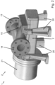
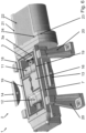
- FIG. 1 A screw pump 1 is shown schematically with the reference number 1.
- the illustration according to Figure 1 shows a screw pump 1, which comprises a multi-part housing 2.
- the housing 2 comprises a running housing part 7 and a connection housing part 15 as well as a drive housing part 21.
- a drain housing can be provided for mounting on the housing parts 7, 15, 21, wherein the drain housing preferably comprises components that enable the screw pump 1 to be drained for maintenance.
- an attachment housing with flushing connections for checking and cleaning the screw pump 1 can be provided.
- a pressure relief valve housing and a bypass housing are also possible for mounting on the modular housing parts 7, 15, 21 of the screw pump 1.
- a mountable pressure compensation housing with lines for pressure compensation of the screw spindle pump rotors can also be provided on the housing 2 of the screw pump 1.
- the attachment of a separate recirculation housing can be provided, for example to provide controlled recirculation of fluid when capacity is adjusted.
- a safety valve adapter housing as an attachment to the housing parts 7, 15, 21 of the screw pump 1, via which safety valves or bursting disks can be connected.
- An attachable gear cover is also possible.
- Other modular additional housings with additional functions are possible.
- cover plates 25 are provided on the running housing part 7, which can be removed to install an additional housing.
- the cover plates 25 also serve to simplify maintenance, since they cover openings into the interior of the pump housing 2, for example to the suction chamber 11.
- the suction-side connection element 13 and the pressure-side connection element 14 are arranged on a common connection housing part 15 of the multi-part housing 2.
- connection housing part 15 is designed in one piece. This facilitates assembly with the other housing parts 7, 21 of the pump 1, since fewer parts have to be aligned with each other.
- the separate design of the connection housing part 15 makes it possible to change the position of the connection elements 13, 14 on the connection housing part 15 by replacing this component, without any changes to the running housing part 7 being necessary. This makes it possible, for example, to change the conveying direction of the pump 1 without the running housing part 7 having to be adjusted.
- the connection housing part 15 has a total of four support feet 20 in order to be able to support itself independently from the ground. Foot heating is provided on the support feet 20.
- the running housing part 7 can be heated using these or other attachable heating elements, e.g. to achieve the desired viscosity of the conveyed fluid. Fluids to ensure.
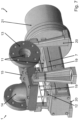
- the Figure 2 shows a screw pump 1 schematically. Compared to Figure 1 the perspective is changed so that a better view of the suction-side connection element 14 is possible.
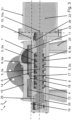
- the Figure 3 shows a schematic sectional view through the housing 2 of a screw pump 1 according to the invention along a rotor 3, 3a of the screw pump 1.
- the screw pump 1 comprises two coupled, chamber-forming rotors 3, 3a, each with at least one thread-shaped profile 4, 4a formed at least in some areas with screw-shaped channels 5, 5a and with partition walls 6, 6a delimiting the channels 5, 5a.
- the rotors 3, 3a rotate in opposite directions about the rotor axes 10, 10a, so that the partition walls 6, 6a of the two rotors 3, 3a mesh with one another like gears.
- the rotor housing part 7 forms the outer wall for the rotors 3, 3a with a spindle bore 9.
- the rotors 3, 3a form a plurality of delivery chambers 8, 8a for the fluid to be delivered with the rotor housing part 7.
- the delivery chambers 8, 8a move axially along the rotor axes 10, 10a due to the rotation of the rotors 3, 3a.
- the fluid is conveyed from a suction chamber 11 into a pressure chamber 12.
- further rotors can be provided in the screw pump 1.
- the rotors 3, 3a are mounted in the rotor housing part 7 via bearings 26.
- connection housing part 15 and the rotor housing part 7 together form the suction chamber 11 and the pressure chamber 12.
- the connection housing part 15 has a partition wall 17 between the suction chamber 11 and the pressure chamber 12.
- a pressure compensation element 18 is arranged in the partition wall 17, which can divert an overpressure generated in the pressure chamber 12 in the direction of the suction chamber 11 as an overload valve and thus prevent damage to the pump and the pipe system connected to the screw pump 1.
- the housing 2 has a flat division plane 16 running parallel to the rotor axes 10, 10a.
- This division plane 16 forms a connection flange between the connection housing part 15 and the rotor housing part 7.
- the rotors 3, 3a are driven for pumping operation via a drive 22 arranged in a drive housing part 21 of the multi-part housing 2.
- This drive 22 comprises a magnetic coupling which is arranged in a drive housing part 21 designed as a flange housing.
- a further flat division plane 23 is advantageously provided between the rotor housing part 7 and the drive housing part 21.
- a further flat seal 24 is arranged on this division plane 23 between the running housing part 7 and the drive housing part 21.
- the further add-on additional housings are preferably also connected to the pump housing 2 via planar division planes and are further preferably sealed against one another via further flat seals on these division planes. Further division planes are also possible within the running housing part 7, the connection housing part 15 or the drive housing part 21. Here too, further flat seals are suitable for sealing the housing parts against one another.
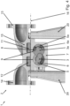
- the Figure 4 discloses a schematic sectional view through the modular housing 2 of a screw pump 1 according to the invention from the perspective of the rotor axes 10, 10a ( Fig.3 ).
- the multi-part housing 2 of the screw pump 1 comprises the rotor housing part 7, which encloses the two rotors 3, 3a in an 8-shaped spindle bore 9 without contact.
- the rotor housing part 7 thus forms the outer wall for the rotors 3, 3a.
- the rotors 3, 3a form several delivery chambers 8, 8a with the rotor housing part 7 ( Fig.3 ) for the fluid to be pumped.
- connection flanges 13, 14 can be used as connection elements 13, 14 in this area.
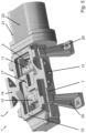
- the Figure 7 discloses a schematic exploded view of a screw pump 1 according to the invention.
- the connection housing part 15 is raised from the running housing part 7, so that the flat seal 19, which is also raised, and the suction chamber 11 and the pressure chamber 12 can be seen.
- a particular advantage is that all pump elements can be pre-assembled and tested in the rotor housing part 7 before assembly with the connection housing part 15, including the seals or the magnetic drive.
- a multi-stage pump By arranging several barrel housing parts 7 on top of each other, i.e. stacking the barrel housing parts 7, a multi-stage pump can advantageously be realized.
- connection housing parts 15 can be provided on several sides of the barrel housing part 7.
Landscapes
- Engineering & Computer Science (AREA)
- Mechanical Engineering (AREA)
- General Engineering & Computer Science (AREA)
- Rotary Pumps (AREA)
- Details And Applications Of Rotary Liquid Pumps (AREA)
Description
- Die Erfindung betrifft eine Schraubenpumpe oder Schraubenspindelpumpe, insbesondere eine ein- oder mehrflutige Doppelschraubenpumpe oder Doppelschraubenspindelpumpe, umfassend ein mehrteiliges Gehäuse und wenigstens zwei gekoppelte, kammerbildende Rotoren mit jeweils wenigstens einer zumindest bereichsweise ausgebildeten, gewindeförmigen Profilierung mit schraubenförmigen Kanälen und mit die Kanäle begrenzenden Trennwänden, wobei die Rotoren eine gegensinnige Rotordrehung ausüben und die Trennwände zahnradartig ineinandergreifen, ein Laufgehäuseteil, wobei das Laufgehäuseteil die Rotoren kontaktfrei umschließt, wobei die Rotoren mit dem Laufgehäuseteil wenigstens eine F-örderkammer für das zu fördernde Fluid bilden, wobei die Förderkammer axial entlang der Rotorenachsen wandert und das Fluid von einem Saugraum in einen Druckraum fördert, ein mit dem Saugraum fluidtechnisch verbundenes saugseitiges Anschlusselement und ein mit dem Druckraum fluidtechnisch verbundenes druckseitiges Anschlusselement.
- Derartige Schraubenpumpen sind aus der
DE 716 161 A ,DE 197 49 572 A1 ,DE 20 01 000 A ,DE 20 01 015 A ,GB 645 817 A US 5 601 414 A bekannt. Eine solche Pumpe eignet sich zur Förderung von Fluiden, wie beispielsweise flüssigem Kunststoff oder anderen chemischen Produkten. Nachteilig an der vorbekannten Pumpe ist jedoch der hohe Fertigungs- und Wartungsaufwand. Insbesondere die Lagerung der Rotoren in der abnehmbaren Seitenwand des Pumpengehäuses sorgt für aufwendige Justierungen der Rotoren nach Zerlegung der Pumpe zur Reinigung und Wartung. Die Herstellung aus Stahlguss ist aufgrund der komplizierten Form und abschnittsweiser Doppelwandigkeit zwischen Spindelbohrung und Pumpengehäuse schwierig. - Die
EP 2 606 234 A2 betrifft eine Drehkolbenpumpe zur Förderung eines Feststoffe enthaltenden fluiden Mediums, umfassend eine Einlassöffnung und eine Auslassöffnung für das zu fördernde Medium, zwei in einem Pumpengehäuse angeordnete Drehkolben mit ineinandergreifenden Drehkolbenflügeln, wobei jeder der beiden Drehkolben drehmomentfest auf jeweils einer Welle befestigt und durch die jeweilige Welle antreibbar ist, und wobei die beiden Wellen durch ein in einem Getriebegehäuse angeordnetes Getriebe miteinander gekoppelt sind, wobei die Einlassöffnung und die Auslassöffnung an einem Anschlussgehäuse angeordnet sind. - Der Erfindung stellt sich somit das Problem, eine Schraubenpumpe anzugeben, die eine einfache Fertigung und Wartung ermöglicht.
- Erfindungsgemäß wird dieses Problem durch eine Schraubenpumpe mit den Merkmalen des Patentanspruchs 1 gelöst.
- Erfindungsgemäß zeichnet sich die Schraubenpumpe dadurch aus, dass das saugseitige Anschlusselement und das druckseitige Anschlusselement an einem Anschlussgehäuseteil des mehrteiligen Gehäuses angeordnet sind, wobei das Gehäuse zwischen dem Laufgehäuseteil und dem Anschlussgehäuseteil eine weitgehend plane, parallel zu den Rotorenachsen verlaufende Teilungsebene aufweist.
- Dadurch ist eine deutlich einfachere Fertigung und Wartung möglich. Außerdem kann eine modulare Bauart der Pumpe erreicht werden, indem sich unterschiedliche Laufgehäuseteile und unterschiedliche Anschlussgehäuseteile miteinander kombinieren lassen. Zudem kommen die Gehäuseteile nahezu ohne Hinterschneidungen und ohne doppelte Wandungen aus, sodass die Fertigung der Teile im Gussverfahren deutlich vereinfacht wird. Hierdurch lassen sich neben Guss auch Sondermaterialien gut verarbeiten. Die plane Teilungsebene bietet zudem einfache und langlebige Abdichtungsmöglichkeiten zwischen den Gehäuseteilen des Pumpengehäuses an. Die Anordnung des saugseitigen und druckseitigen Anschlusselementes in einem gemeinsamen Anschlussgehäuseteil, welches sich durch die Teilungsebene vom Laufgehäuseteil einfach trennen lässt, ermöglicht es zudem, dass das Anschlussgehäuseteil bei Wartungsarbeiten im Rohrverbund verbleibt. Das heißt bei Wartungsarbeiten können das saugseitige und das druckseitige Anschlusselement mit den Rohren, verbunden bleiben.
- Unter mehrflutigen Schraubenpumpen werden Pumpen verstanden, in deren Laufgehäuseteil zwei oder mehr Schraubenpaare angeordnet sind, die dann parallel zwischen einem gemeinsamen Druckraum und einem gemeinsamen Saugraum arbeiten.
- Gemäß einer vorteilhaften Ausgestaltung der Erfindung ist vorgesehen, dass die Teilungsebene durch den Saugraum und den Druckraum verläuft. Ein derartiger Verlauf der Teilungsebene bietet Vorteile hinsichtlich der Modularität und der Wartung. Zudem hat ein derartiger Verlauf der Teilungsebene weitere Vorteile bei der Fertigung, da kaum Hinterschneidungen erforderlich sind. Die Teilungsebene verläuft nicht innerhalb der Spindelachsen, so dass diese bei Demontage von Laufgehäuseteil und Anschlussgehäuseteil nicht direkt freigelegt werden.
- Eine vorteilhafte Ausführung ist, dass die Rotoren in dem Laufgehäuseteil gelagert sind. Die Zentrierung der Lagerung oder die Lagerung selber sind im Laufgehäuseteil enthalten. Die Lagerung der Rotoren im Laufgehäuseteil macht die Montage bei der Fertigung einfacher und reduziert zudem den Aufwand bei der Wartung der Pumpe. Zur Lagerung der Rotoren in dem Laufgehäuseteil weist dieses auch die Zentrierungen für die Lagerung der Rotoren auf. Außerdem lässt sich die Position der Rotoren in dem Laufgehäuseteil aufgrund der besseren Zugänglichkeit vor der Verbindung mit dem Anschlussgehäuseteil überprüfen. Hierdurch kann einfach sichergestellt werden, dass das Laufgehäuseteil die Rotoren kontaktfrei umschließt und dass die Rotoren mit dem Laufgehäuseteil mindestens eine dichte Förderkammer ausbilden.
- Gemäß einer vorteilhaften Ausgestaltung der Erfindung ist vorgesehen, dass das Laufgehäuseteil einteilig ausgebildet ist. Die einteilige Ausbildung des Laufgehäuseteils bietet besondere Vorteile bei der Ausrichtung und Lagerung der Rotoren in dem Laufgehäuseteil. Die einteilige Ausführung des Laufgehäuseteils bietet insbesondere zusammen mit der Lagerung der Rotoren in dem Laufgehäuseteil den Vorteil, dass bei der Positionierung der Rotoren keine zusätzlichen Toleranzen bei der Montage berücksichtigt werden müssen. Solche zusätzlichen Toleranzen ergeben sich üblicherweise dadurch, dass das Gehäuseteil, welches mit den Rotoren die Förderkammer ausbildet von dem Bauteil, welches die Rotoren lagert, verschieden ist.
- Besonders vorteilhaft ist die Weiterbildung, dass das Anschlussgehäuseteil einteilig ausgebildet ist. Eine einteilige Ausgestaltung des Anschlussgehäuseteils erleichtert die Montage mit den weiteren Gehäuseteilen der Pumpe und dem mit der Pumpe verbundenen Rohrsystem. Auch die Fertigung des Anschlussgehäuseteils ist durch die einteilige Ausbildung deutlich vereinfacht.
- Eine bevorzugte Ausführung sieht vor, dass das Anschlussgehäuseteil mit dem Laufgehäuseteil zusammen den Saugraum und den Druckraum bildet. Die Bildung des Saugraums und des Druckraums durch das Anschlussgehäuseteil und das Laufgehäuseteil bietet eine einfache Zugänglichkeit der durch die Gehäuseteile gebildeten Räume bei Demontage des Laufgehäuseteils vom Anschlussgehäuseteil.
- Besonders vorteilhaft ist die Weiterbildung, dass das Anschlussgehäuseteil eine Trennwand zwischen dem Saugraum und dem Druckraum aufweist. Diese Trennwand kann abhängig von den Erfordernissen am Einsatzort der Pumpe unterschiedlich gestaltet sein, um beispielsweise die Förderrichtung der Pumpe anzupassen. Ist eine sogenannte "in line"-Konfiguration der Anschlusselemente erforderlich, kann die Trennwand zwischen dem Saugraum und dem Druckraum anders ausgestaltet sein als bei anderen gewünschten Konfigurationen des Anschlussgehäuseteils, bei denen die Anschlusselemente versetzt zueinander oder unter einem Winkel angeordnet sind. Die Trennung von Laufgehäuseteil und Anschlussgehäuseteil schafft hier ebenfalls flexible Anpassungsmöglichkeiten der Pumpe durch die gewonnene Modularität.
- Weiter vorteilhaft ist die Ausgestaltung, dass in der Trennwand ein Druckausgleichselement angeordnet ist. Das Druckausgleichselement zwischen Druckraum und Saugraum verhindert Schäden an der Pumpe, sollte beispielsweise das an den Druckraum angeschlossene Rohrsystem verstopft sein. In diesem Fall würde das als Überlastungsventil ausgestaltete Druckausgleichselement den im Druckraum erzeugten Überdruck Richtung Saugraum ableiten und so Schäden an der Pumpe und dem Rohrsystem verhindern. Von besonderem Vorteil ist die Anordnung eines Druckausgleichelements in der Trennwand, da dies mit geringem Montageaufwand zu bewerkstelligen ist und die Konstruktion fehlerunanfällig ist.
- Eine vorteilhafte Ausführungsform der Erfindung sieht mehrere zu den Rotorachsen parallele Teilungsebenen vor. Auf diesen zusätzlichen Teilungsebenen, die den gleichen Zugang zu Saug- und Druckraum der Pumpe wie die erste Teilungsebene zum Anschlussgehäuse bieten, können weitere Zusatzfunktionen wie z.B. Druckabsicherung, Spülanschlüsse, Bypasspasseinrichtungen, etc. bereitgestellt werden.
- Eine vorteilhafte Ausführungsform der Erfindung sieht vor, dass zwischen dem Laufgehäuseteil und dem Anschlussgehäuseteil eine Flachdichtung angeordnet ist. Die plane Ausgestaltung der Teilungsebene zwischen Laufgehäuseteil und Anschlussgehäuseteil ermöglicht die Verwendung einer Flachdichtung zwischen den Gehäuseteilen der Pumpe. Hier ist von besonderem Vorteil, dass Flachdichtungen sich relativ einfach montieren lassen und langlebig sowie fehlerunanfällig sind. Insbesondere hinsichtlich der Medien- und Temperaturbeständigkeit bieten die Flachdichtungen enorme Vorteile.
- Eine alternative Ausführungsform der Erfindung sieht vor, dass zwischen dem Laufgehäuseteil und dem Anschlussgehäuseteil eine O-Ring-Dichtung angeordnet ist.
- Gemäß der Erfindung ist vorgesehen, dass an dem Anschlussgehäuseteil mindestens ein Stützfuß vorgesehen ist. Die Anordnung eines Stützfußes an dem Anschlussgehäuseteil ermöglicht es, dass sich das Anschlussgehäuseteil selbstständig vom Boden abstützt. Dies ist von besonderem Vorteil, wenn das Laufgehäuseteil zur Wartung demontiert ist und das Anschlussgehäuseteil im verbundenen Rohrverbund verbleibt. Hierdurch belastet das Anschlussgehäuseteil bei den Wartungsarbeiten den Rohrverbund nicht. Außerdem ist hierdurch eine Mittenaufhängung möglich. Zudem kann hierdurch das Laufgehäuseteil mechanisch entkoppelt sein.
- Eine bevorzugte Ausführung sieht vor, dass die Rotoren über einen in einem Antriebsgehäuseteil des mehrteiligen Gehäuses angeordneten Antrieb antreibbar sind. Die Anordnung des Antriebes in einem Antriebsgehäuseteil erhöht die Modularität der Pumpengehäuseteile. So können unterschiedliche Laufgehäuseteile und Anschlussgehäuseteile mit verschiedenen Antrieben kombiniert werden, um die Schraubenpumpe an die Erfordernisse des Einsatzzweckes und -ortes optimal anpassen zu können. Der Antrieb kann direkt über eine aus dem Gehäuse geführte Welle angeschlossen sein kann.
- Gemäß einer vorteilhaften Ausgestaltung der Erfindung ist vorgesehen, dass der Antrieb eine Magnetkupplung umfasst. Mit der Einbindung einer Magnetkupplung in den Antrieb der Schraubenpumpe ist eine mechanische Trennung zwischen Fördermedium und Antriebsaggregat realisierbar, die die sichere Förderung beispielsweise von brennbaren oder sonstwie reaktiven oder giftigen Fluiden ermöglicht.
- Weiter vorteilhaft ist die Ausgestaltung, dass das Gehäuse zwischen dem Laufgehäuseteil und dem Antriebsgehäuseteil eine plan verlaufende Teilungsebene aufweist. Die plane Teilungsebene bietet einfache und langlebige Abdichtungsmöglichkeiten zwischen den Gehäuseteilen des Pumpengehäuses an.
- Weiter vorteilhaft ist die Ausgestaltung, dass zwischen dem Laufgehäuseteil und dem Antriebsgehäuseteil eine Flachdichtung angeordnet ist. Die plane Ausgestaltung der Teilungsebene zwischen Laufgehäuseteil und Antriebsgehäuseteil ermöglicht die Verwendung einer Flachdichtung zwischen den Gehäuseteilen der Pumpe. Hier ist von besonderem Vorteil, dass Flachdichtungen sich relativ einfach montieren lassen, preiswert, langlebig sowie fehlerunanfällig sind.
- Eine alternative Ausführungsform der Erfindung sieht vor, dass zwischen dem Laufgehäuseteil und dem Antriebsgehäuseteil eine O-Ring-Dichtung angeordnet ist.
- Eine weitere vorteilhafte Ausführung ist, dass das Laufgehäuseteil beheizbar ist. Mit dem Laufgehäuseteil sind damit auch die direkt im Laufgehäuseteil platzierten Rotoren direkt beheizbar. Durch die direkte Beheizung des Laufgehäuseteils ist eine Förderung von Medien möglich, die nur in erwärmtem Zustand flüssig sind. Hierbei kann es sich insbesondere um Kunststoffe, beispielsweise MDI-Kunststoffe, handeln.
- Weitere Merkmale, Einzelheiten und Vorteile der Erfindung ergeben sich aufgrund der nachfolgenden Beschreibung sowie anhand der Zeichnungen. Ausführungsbeispiele der Erfindung sind in den folgenden Zeichnungen rein schematisch dargestellt und werden nachfolgend näher beschrieben. Einander entsprechende Gegenstände oder Elemente sind in allen Figuren mit den gleichen Bezugszeichen versehen. Es zeigen:
- Figur 1
- schematische Darstellung einer erfindungsgemäßen Schraubenpumpe;
- Figur 2
- weitere schematische Darstellung einer erfindungsgemäßen Schraubenpumpe;
- Figur 3
- schematische Schnittdarstellung einer erfindungsgemäßen Schraubenpumpe;
- Figur 4
- weitere schematische Schnittdarstellung einer erfindungsgemäßen Schraubenpumpe;
- Figur 5
- weitere schematische Schnittdarstellung einer erfindungsgemäßen Schraubenpumpe;
- Figur 6
- weitere schematische Schnittdarstellung einer erfindungsgemäßen Schraubenpumpe;
- Figur 7
- schematische Explosionsdarstellung einer erfindungsgemäßen Schraubenpumpe;
- In
Figur 1 mit dem Bezugszeichen 1 bezeichnet ist eine Schraubenpumpe 1 schematisch dargestellt. Die Darstellung gemäßFigur 1 zeigt eine Schraubenpumpe 1, die ein mehrteiliges Gehäuse 2 umfasst. Das Gehäuse 2 umfasst ein Laufgehäuseteil 7 und ein Anschlussgehäuseteil 15 sowie ein Antriebsgehäuseteil 21. - Neben diesen Gehäuseteilen 7, 15, 21 können weitere Gehäuseteilkomponenten zum Anbau an diese Gehäuseteile 7, 15, 21 vorgesehen sein. So kann ein Entleerungsgehäuse zur Montage an den Gehäuseteilen 7, 15, 21 vorgesehen sein, wobei das Entleerungsgehäuse vorzugsweise Komponenten umfasst, die eine Entleerung der Schraubenpumpe 1 zur Wartung ermöglichen. Zudem kann ein Anbaugehäuse mit Spülanschlüssen zum Prüfen und Reinigen der Schraubenpumpe 1 vorgesehen sein. Auch ein Druckbegrenzungsventilgehäuse sowie ein Bypassgehäuse sind zur Montage an den modulartig aufgebauten Gehäuseteilen 7, 15, 21 der Schraubenpumpe 1 möglich. An dem Gehäuse 2 der Schraubenpumpe 1 kann zudem ein montierbares Druckausgleichsgehäuse mit Leitungen zum Druckausgleich der Schraubenspindelpumpenrotoren vorgesehen sein. Weiterhin kann der Anbau eines separaten Rezirkulationsgehäuse, beispielsweise zur Bereitstellung einer kontrollierten Rezirkulation von Fluid bei Kapazitätsanpassungen, vorgesehen sein. Außerdem ist denkbar, ein Sicherheitsventil-Adapter-Gehäuse als Anbauteil an die Gehäuseteile 7, 15, 21 der Schraubenpumpe 1 vorzusehen, über welches Sicherheitsventile oder Berstscheiben anschließbar sind. Auch eine anbaubare Getriebehaube ist vorsehbar. Weitere modulartige Zusatzgehäuse mit zusätzlichen Funktionen sind möglich. Um die modulartigen Zusatzgehäuse (nicht gezeigt) an dem Gehäuse 2 der Schraubenpumpe 1 anzubauen sind an dem Laufgehäuseteil 7 mehrere Abdeckplatten 25 vorgesehen, die zur Montage eines Zusatzgehäuses entfernt werden können. Die Abdeckplatten 25 dienen auch der einfacheren Wartung, da sie Öffnungen in das Innere des Pumpengehäuses 2, beispielsweise zu dem Saugraum 11, abdecken. Wie gut in
Figur 1 zu erkennen ist, sind das saugseitige Anschlusselement 13 und das druckseitige Anschlusselement 14 an einem gemeinsamen Anschlussgehäuseteil 15 des mehrteiligen Gehäuses 2 angeordnet. Das Anschlussgehäuseteil 15 ist einteilig ausgebildet. Dies erleichtert die Montage mit den weiteren Gehäuseteilen 7, 21 der Pumpe 1, da weniger Teile zueinander ausgerichtet werden müssen. Die separate Ausgestaltung des Anschlussgehäuseteils 15 ermöglicht es durch Austausch dieses Bauteils die Position der Anschlusselemente 13, 14 auf dem Anschlussgehäuseteil 15 zu verändern, ohne dass hierfür Änderungen an dem Laufgehäuseteil 7 erforderlich sind. Hierdurch kann beispielsweise die Förderrichtung der Pumpe 1 verändert werden, ohne dass das Laufgehäuseteil 7 angepasst werden muss. Das Anschlussgehäuseteil 15 hat insgesamt vier Stützfüße 20 um sich selbständig vom Untergrund abstützen zu können. An den Stützfüßen 20 ist eine Fußheizung vorgesehen. Über diese oder weitere anbaubare Heizelemente ist das Laufgehäuseteil 7 beheizbar, z.B. um die gewünschte Viskosität des geförderten Fluids zu gewährleisten. - Die
Figur 2 zeigt eine Schraubenpumpe 1 schematisch dargestellt. GegenüberFigur 1 ist die Perspektive geändert, so dass ein besserer Blick auf das saugseitige Anschlusselement 14 möglich ist. - Die
Figur 3 zeigt eine schematische Schnittdarstellung durch das Gehäuse 2 einer erfindungsgemäßen Schraubenpumpe 1 entlang eines Rotors 3, 3a der Schraubenpumpe 1. Die Schraubenpumpe 1 umfasst zwei gekoppelte, kammerbildende Rotoren 3, 3a mit jeweils wenigstens einer zumindest bereichsweise ausgebildeten, gewindeförmigen Profilierung 4, 4a mit schraubenförmigen Kanälen 5, 5a und mit die Kanäle 5, 5a begrenzenden Trennwänden 6, 6a. Die Rotoren 3, 3a üben im Pumpbetrieb eine gegensinnige Rotordrehung um die Rotorachsen 10, 10a aus, so dass die Trennwände 6, 6a der beiden Rotoren 3, 3a zahnradartig ineinandergreifen. Das Laufgehäuseteil 7 bildet mit einer Spindelbohrung 9 die Außenwandung für die Rotoren 3, 3a. Die Rotoren 3, 3a bilden mit dem Laufgehäuseteil 7 mehrere Förderkammern 8, 8a für das zu fördernde Fluid aus. Im Pumpbetrieb wandern die Förderkammern 8, 8a aufgrund der Rotation der Rotoren 3, 3a axial entlang der Rotorenachsen 10, 10a. Hierdurch wird das Fluid von einem Saugraum 11 in einen Druckraum 12 gefördert. Auch wenn im Ausführungsbeispiel lediglich zwei kammerbildende Rotoren 3, 3a (Fig. 4 ) gezeigt sind, ist die Erfindung nicht darauf beschränkt. So können weitere Rotoren in der Schraubenpumpe 1 vorgesehen sein. Die Rotoren 3, 3a sind über Lager 26 in dem Laufgehäuseteil 7 gelagert. Hierzu sind im Laufgehäuseteil 7 Aufnahmen oder Zentrierungen der Lagerung untergebracht. Durch die einteilige Ausbildung des Laufgehäuseteils 7 kann die Ausrichtung und Lagerung der Rotoren 3, 3a in dem Laufgehäuseteil 7 sehr einfach erfolgen. Die einteilige Ausführung des Laufgehäuseteils 7 bietet insbesondere zusammen mit der Lagerung der Rotoren 3, 3a in dem Laufgehäuseteil 7 die Möglichkeit, bei der Positionierung der Rotoren 3, 3a keine zusätzlichen Toleranzen durch weitere Bauteile berücksichtigen zu müssen. Wie zu erkennen ist, bildet das Anschlussgehäuseteil 15 mit dem Laufgehäuseteil 7 zusammen den Saugraum 11 und den Druckraum 12. Das Anschlussgehäuseteil 15 weist zwischen dem Saugraum 11 und dem Druckraum 12 eine Trennwand 17 auf. In der Trennwand 17 ist ein Druckausgleichselement 18 angeordnet, das als Überlastungsventil ein im Druckraum 12 erzeugten Überdruck in Richtung Saugraum 11 ableiten kann und so Schäden an der Pumpe und dem mit der Schraubenpumpe 1 verbundenen Rohrsystems verhindert. Zwischen dem Laufgehäuseteil 7 und dem Anschlussgehäuseteil 15 weist das Gehäuse 2 eine plane, parallel zu den Rotorenachsen 10, 10a verlaufende Teilungsebene 16 auf. Diese Teilungsebene 16 bildet einen Anschlussflansch zwischen dem Anschlussgehäuseteil 15 und dem Laufgehäuseteil 7. Die Rotoren 3, 3a sind für den Pumpbetrieb über einen in einem Antriebsgehäuseteil 21 des mehrteiligen Gehäuses 2 angeordneten Antrieb 22 angetrieben. Dieser Antrieb 22 umfasst eine Magnetkupplung, die in einem als Flanschgehäuse ausgebildeten Antriebsgehäuseteil 21 angeordnet ist. Zwischen dem Laufgehäuseteil 7 und dem Antriebsgehäuseteil 21 ist vorteilhafterweise eine weitere plan verlaufende Teilungsebene 23 vorgesehen. Auf dieser Teilungsebene 23 zwischen dem Laufgehäuseteil 7 und dem Antriebsgehäuseteil 21 ist eine weitere Flachdichtung 24 angeordnet. Die weiteren anbaubaren Zusatzgehäuse sind vorzugsweise ebenfalls über plan verlaufende Teilungsebenen mit dem Pumpengehäuse 2 verbunden und weiter vorzugsweise über weitere Flachdichtungen auf diesen Teilungsebenen gegeneinander abgedichtet. Weitere Teilungsebenen auch innerhalb des Laufgehäuseteils 7, des Anschlussgehäuseteil 15 oder des Antriebsgehäuseteils 21 sind möglich. Auch hier bieten sich weitere Flachdichtungen zur Abdichtung der Gehäuseteile gegeneinander an. - Die
Figur 4 offenbart eine schematische Schnittdarstellung durch das modulartige Gehäuse 2 einer erfindungsgemäßen Schraubenpumpe 1 aus Sicht der Rotorachsen 10, 10a (Fig. 3 ). Das mehrteilige Gehäuse 2 der Schraubenpumpe 1 umfasst das Laufgehäuseteil 7, welches die beiden Rotoren 3, 3a in einer 8-förmigen Spindelbohrung 9 kontaktfrei umschließt. Das Laufgehäuseteil 7 bildet so die Außenwandung für die Rotoren 3, 3a. Die Rotoren 3, 3a bilden mit dem Laufgehäuseteil 7 mehrere Förderkammern 8, 8a (Fig. 3 ) für das zu fördernde Fluid aus. Im Pumpbetrieb wandern die Förderkammern 8, 8a (Fig. 3 ) aufgrund der Rotation der Rotoren 3, 3a axial entlang der Rotorenachsen 10, 10a (Fig. 3 ). Hierdurch wird das Fluid von dem Saugraum 11 in den Druckraum 12 gefördert. Über ein mit dem Saugraum 11 fluidtechnisch verbundenes saugseitiges Anschlusselement 13 wird im Pumpbetrieb das zu fördernde Medium aus einem mit dem Anschlusselement 13 verbundenen Rohrsystem in den Saugraum 11 geleitet. Ein mit dem Druckraum 12 fluidtechnisch verbundenes druckseitiges Anschlusselement 14 schafft eine Verbindung zu einem Rohrsystem in welches das geförderte Medium gleitet wird. Als Anschlusselement 13, 14 in dem Bereich kommen, wie im Ausführungsbeispiel gezeigt, Anschlussflansche 13, 14 in Frage. Das Gehäuse 2 weist zwischen dem Laufgehäuseteil 7 und dem Anschlussgehäuseteil 15 eine weitgehend plane, weitgehend parallel zu den Rotorenachsen 10, 10a verlaufende Teilungsebene 16 auf. Diese Teilungsebene 16 bildet einen Anschlussflansch zwischen dem Anschlussgehäuseteil 15 und dem Laufgehäuseteil 7. Das Anschlussgehäuseteil 15 verbindet die Prozess-Anschlüsse (Saugleitung, Druckleitung) an den Anschlusselementen 13, 14 mit dem Laufgehäuseteil 7. - Die
Figur 5 zeigt eine schematische Schnittdarstellung einer erfindungsgemäßen Schraubenpumpe 1 durch das Anschlussgehäuseteil 15 und das Antriebsgehäuseteil 21 mit Antrieb 22. Die Schnittebene verläuft parallel zu den Rotorenachsen 10, 10a (Fig. 3 ) und der Teilungsebene 16 (Fig. 4 u. 6). Es ist gut zu erkennen, dass das Anschlussgehäuseteil 15 mit dem Laufgehäuseteil 7 zusammen den Saugraum 11 und den Druckraum 12 bildet. Das Anschlussgehäuseteil 15 weist eine Trennwand 17 zwischen dem Saugraum 11 und dem Druckraum 12 auf. Diese Trennwand 17 kann abhängig von den Erfordernissen am Einsatzort der Pumpe 1 unterschiedlich gestaltet sein, um beispielsweise die Förderrichtung der Pumpe 1 anzupassen. - Die
Figur 6 zeigt eine schematische Schnittdarstellung einer erfindungsgemäßen Schraubenpumpe 1 durch die Teilungsebene 16 (Fig. 4 ). Wie zu erkennen ist, verläuft die Teilungsebene 16 durch den Saugraum 11 und den Druckraum 12. Es ist weiter gut zu erkennen, dass zwischen dem Laufgehäuseteil 7 und dem Anschlussgehäuseteil 15 (Fig. 4 ) eine Flachdichtung 19 auf der planen Teilungsebene 16 angeordnet ist. Da der Schnitt auch durch das Antriebsgehäuseteil 21 und den Antrieb 22 verläuft, ist auf der Teilungsebene 23 zwischen dem Antriebsgehäuseteil 21 und dem Laufgehäuseteil 7 die zwischen den Gehäuseteilen befindliche Flachdichtung 24 zu sehen. - Die
Figur 7 offenbart eine schematische Explosionsdarstellung einer erfindungsgemäßen Schraubenpumpe 1. Hierbei ist das Anschlussgehäuseteil 15 vom Laufgehäuseteil 7 angehoben, so dass die ebenfalls angehobene Flachdichtung 19 und der Saugraum 11 sowie der Druckraum 12 zu sehen sind. - Von besonderem Vorteil ist, dass alle Pumpenelemente vor Montage mit dem Anschlussgehäuseteil 15 im Laufgehäuseteil 7 vormontierbar und testbar sind, inklusive der Dichtungen oder des Magnetantriebs.
- Durch die Anordnung mehrerer Laufgehäuseteile 7 aufeinander, also ein Stapeln der Laufgehäuseteile 7, kann mit Vorteil eine mehrstufige Pumpe realisiert werden.
- Außerdem können mehrere Anschlussgehäuseteile 15 an mehreren Seiten des Laufgehäuseteils 7 vorgesehen sein.
-
- 1
- Schraubenpumpe
- 2
- Gehäuse
- 3
- 3a Rotoren
- 4
- 4a Profilierung
- 5
- 5a schraubenförmige Kanäle
- 6
- 6a Trennwände
- 7
- Laufgehäuseteil
- 8
- Förderkammer
- 9
- Spindelbohrung
- 10
- 10a Rotorenachsen
- 11
- Saugraum
- 12
- Druckraum
- 13
- saugseitiges Anschlusselement
- 14
- druckseitiges Anschlusselement
- 15
- Anschlussgehäuseteil
- 16
- Teilungsebene A
- 17
- Trennwand
- 18
- Druckausgleichselement
- 19
- Flachdichtung A
- 20
- Stützfuß
- 21
- Antriebsgehäuseteil
- 22
- Antrieb
- 23
- Teilungsebene B
- 24
- Flachdichtung B
- 25
- Abdeckplatte
- 26
- Lager
Claims (16)
- Schraubenpumpe (1), insbesondere ein- oder mehrflutige Doppelschraubenpumpe, umfassend ein mehrteiliges Gehäuse (2, 7, 15, 21) und wenigstens zwei gekoppelte, kammerbildende Rotoren (3, 3a) mit jeweils wenigstens einer zumindest bereichsweise ausgebildeten, gewindeförmigen Profilierung (4, 4a) mit schraubenförmigen Kanälen (5, 5a) und mit die Kanäle (5, 5a) begrenzenden Trennwänden (6, 6a), wobei die Rotoren (3, 3a) eine gegensinnige Rotordrehung ausüben und die Trennwände (6, 6a) zahnradartig ineinandergreifen, ein Laufgehäuseteil (7), wobei das Laufgehäuseteil (7) die Rotoren (3, 3a) kontaktfrei umschließt, wobei die Rotoren (3, 3a) mit dem Laufgehäuseteil (7) wenigstens eine Förderkammer (8, 8a) für das zu fördernde Fluid bilden, wobei die Förderkammer (8, 8a) axial entlang der Rotorenachsen (10, 10a) wandert und das Fluid von einem Saugraum (11) in einen Druckraum (12) fördert, ein mit dem Saugraum (11) fluidtechnisch verbundenes saugseitiges Anschlusselement (13) und ein mit dem Druckraum (12) fluidtechnisch verbundenes druckseitiges Anschlusselement (14),
dadurch gekennzeichnet, dass das saugseitige Anschlusselement (13) und das druckseitige Anschlusselement (14) an einem Anschlussgehäuseteil (15) des mehrteiligen Gehäuses (2, 7, 15, 21) angeordnet sind, wobei das Gehäuse (2, 7, 15, 21) zwischen dem Laufgehäuseteil (7) und dem Anschlussgehäuseteil (15) eine plane, parallel zu den Rotorenachsen (10, 10a) verlaufende Teilungsebene (16) aufweist, wobei an dem Anschlussgehäuseteil (15) mindestens ein Stützfuß (20) vorgesehen ist. - Schraubenpumpe (1) nach Anspruch 1, dadurch gekennzeichnet, dass die Teilungsebene (16) durch den Saugraum (11) und den Druckraum (12) verläuft.
- Schraubenpumpe (1) nach Anspruch 1 oder 2, dadurch gekennzeichnet, dass die Rotoren (3, 3a) in dem Laufgehäuseteil (7) gelagert sind.
- Schraubenpumpe (1) nach einem der Ansprüche 1 bis 3, dadurch gekennzeichnet, dass das Laufgehäuseteil (7) einteilig ausgebildet ist.
- Schraubenpumpe (1) nach einem der Ansprüche 1 bis 4, dadurch gekennzeichnet, dass das Anschlussgehäuseteil (15) einteilig ausgebildet ist.
- Schraubenpumpe (1) nach einem der Ansprüche 1 bis 5, dadurch gekennzeichnet, dass das Anschlussgehäuseteil (15) mit dem Laufgehäuseteil (7) zusammen den Saugraum (11) und den Druckraum (12) bildet.
- Schraubenpumpe (1) nach einem der Ansprüche 1 bis 6, dadurch gekennzeichnet, dass das Anschlussgehäuseteil (15) eine Trennwand (17) zwischen dem Saugraum (11) und dem Druckraum (12) aufweist.
- Schraubenpumpe (1) nach einem der Ansprüche 7, dadurch gekennzeichnet, dass in der Trennwand (17) ein Druckausgleichselement (18) angeordnet ist.
- Schraubenpumpe (1) nach einem der Ansprüche 1 bis 8, dadurch gekennzeichnet, dass zwischen dem Laufgehäuseteil (7) und dem Anschlussgehäuseteil (15) eine Flachdichtung (19) angeordnet ist.
- Schraubenpumpe (1) nach einem der Ansprüche 1 bis 8, dadurch gekennzeichnet, dass zwischen dem Laufgehäuseteil (7) und dem Anschlussgehäuseteil (15) eine O-Ring-Dichtung angeordnet ist.
- Schraubenpumpe (1) nach einem der Ansprüche 1 bis 10, dadurch gekennzeichnet, dass die Rotoren (3, 3a) über einen in einem Antriebsgehäuseteil (21) des mehrteiligen Gehäuses (2, 7, 15, 21) angeordneten Antrieb (22) antreibbar sind.
- Schraubenpumpe (1) nach Anspruch 11, dadurch gekennzeichnet, dass der Antrieb (22) eine Magnetkupplung umfasst.
- Schraubenpumpe (1) nach Anspruch 11 oder 12, dadurch gekennzeichnet, dass das Gehäuse (2, 7, 15, 21) zwischen dem Laufgehäuseteil (7) und dem Antriebsgehäuseteil (21) eine plan verlaufende Teilungsebene (23) aufweist.
- Schraubenpumpe (1) nach einem der Ansprüche 11 bis 13, dadurch gekennzeichnet, dass zwischen dem Laufgehäuseteil (7) und dem Antriebsgehäuseteil (21) eine Flachdichtung (24) angeordnet ist.
- Schraubenpumpe (1) nach einem der Ansprüche 11 bis 13, dadurch gekennzeichnet, dass zwischen dem Laufgehäuseteil (7) und dem Antriebsgehäuseteil (21) eine O-Ring-Dichtung angeordnet ist.
- Schraubenpumpe (1) nach einem der Ansprüche 1 bis 15, dadurch gekennzeichnet, dass das Laufgehäuseteil (7) beheizbar ist.
Applications Claiming Priority (2)
| Application Number | Priority Date | Filing Date | Title |
|---|---|---|---|
| DE102016120579.6A DE102016120579B3 (de) | 2016-10-27 | 2016-10-27 | Horizontal geteilte Schraubenspindelpumpe |
| PCT/EP2017/077555 WO2018078073A1 (de) | 2016-10-27 | 2017-10-27 | Horizontal geteilte schraubenspindelpumpe |
Publications (3)
| Publication Number | Publication Date |
|---|---|
| EP3532729A1 EP3532729A1 (de) | 2019-09-04 |
| EP3532729B1 EP3532729B1 (de) | 2020-12-30 |
| EP3532729B2 true EP3532729B2 (de) | 2024-09-25 |
Family
ID=60421733
Family Applications (1)
| Application Number | Title | Priority Date | Filing Date |
|---|---|---|---|
| EP17801607.7A Active EP3532729B2 (de) | 2016-10-27 | 2017-10-27 | Horizontal geteilte schraubenspindelpumpe |
Country Status (7)
| Country | Link |
|---|---|
| US (1) | US11530699B2 (de) |
| EP (1) | EP3532729B2 (de) |
| CN (1) | CN110036202B (de) |
| DE (1) | DE102016120579B3 (de) |
| ES (1) | ES2858000T5 (de) |
| RU (1) | RU2019116010A (de) |
| WO (1) | WO2018078073A1 (de) |
Families Citing this family (7)
| Publication number | Priority date | Publication date | Assignee | Title |
|---|---|---|---|---|
| DE102018116772B3 (de) * | 2018-07-11 | 2019-11-07 | Netzsch Pumpen & Systeme Gmbh | Schraubenspindelpumpe und Verfahren zur Wartung einer solchen Schraubenspindelpumpe |
| DE102019128602B3 (de) * | 2019-10-23 | 2021-02-11 | Leistritz Pumpen Gmbh | Schraubenspindelpumpe |
| USD940205S1 (en) * | 2019-11-06 | 2022-01-04 | Leistritz Pumpen Gmbh | Pump for liquids |
| GB2590664A (en) * | 2019-12-23 | 2021-07-07 | Edwards S R O | Sealing between a cover plate and the pumping chamber or a multiple stage pump |
| US20250354549A1 (en) * | 2022-06-10 | 2025-11-20 | Illinois Tool Works Inc. | Screw pump and its components |
| DE102023111244A1 (de) * | 2023-05-02 | 2024-11-07 | Itt Bornemann Gmbh | Doppelflutige Pumpe |
| DE102023111408A1 (de) | 2023-05-03 | 2024-11-07 | Itt Bornemann Gmbh | Einflutige Schraubenspindelpumpe |
Family Cites Families (32)
| Publication number | Priority date | Publication date | Assignee | Title |
|---|---|---|---|---|
| DE716161C (de) * | 1936-08-14 | 1942-01-14 | Franz Burghauser Dipl Ing | Schraubenpumpe mit zwei oder mehreren Spindeln |
| US2381695A (en) * | 1943-03-11 | 1945-08-07 | Laval Steam Turbine Co | Pumping system |
| GB645817A (en) * | 1947-12-10 | 1950-11-08 | Imo Industri Ab | Improvements in screw-pumps or motors |
| US2590560A (en) * | 1948-05-10 | 1952-03-25 | Montelius Carl Oscar Torsten | Screw pump |
| CH459769A (de) * | 1964-09-11 | 1968-07-15 | Bayer Ag | Vorrichtung zur mechanischen Bearbeitung und gleichzeitigen Förderung von Flüssigkeiten und zähflüssigen, plastischen sowie pulverförmigen Massen |
| DE2001015A1 (de) * | 1969-03-25 | 1970-10-08 | Sigma Lutin | Dreispindelpumpe,insbesondere fuer hohe Druecke |
| DE2001000A1 (de) * | 1970-01-10 | 1971-07-15 | Allweiler Ag | Einstelleinrichtung an Schraubenspindelpumpen |
| CH497261A (de) * | 1970-04-01 | 1970-10-15 | Stuedli Hans | Schneckengehäuse einer Doppelschneckenpresse |
| DE2423785C2 (de) * | 1974-05-16 | 1980-06-12 | Werner & Pfleiderer, 7000 Stuttgart | Verschleißeinsatz für das Schneckengehäuse einer Doppelschneckenstrangpresse oder -Spritzgießmaschine |
| US4137006A (en) * | 1977-01-26 | 1979-01-30 | K B Southern, Inc. | Composite horizontally split casing |
| US4551065A (en) * | 1982-12-13 | 1985-11-05 | Becker John H | Composite horizontally or vertically split casing with variable casing ends |
| DE3709912A1 (de) * | 1987-03-26 | 1988-10-06 | Vogelsang Hugo Fass Masch | Vorrichtung zum verteilen von inhomogenen fluessigkeiten, insbesondere guelle |
| US5063661A (en) * | 1990-07-05 | 1991-11-12 | The United States Of America As Represented By The Secretary Of The Air Force | Method of fabricating a split compressor case |
| US5209937A (en) * | 1990-12-17 | 1993-05-11 | Kangas Waino J | Insert for barrel extruders |
| US5601414A (en) * | 1995-09-25 | 1997-02-11 | Imo Industries, Inc. | Interstage liquid/gas phase detector |
| DE19749572A1 (de) * | 1997-11-10 | 1999-05-12 | Peter Dipl Ing Frieden | Trockenlaufender Schraubenverdichter oder Vakuumpumpe |
| JP2001107922A (ja) * | 1999-10-08 | 2001-04-17 | Mitsubishi Heavy Ind Ltd | フランジレスケーシングの締結構造 |
| US6623262B1 (en) * | 2001-02-09 | 2003-09-23 | Imd Industries, Inc. | Method of reducing system pressure pulsation for positive displacement pumps |
| ATE270393T1 (de) * | 2001-04-03 | 2004-07-15 | Cfs Slagelse As | Schneckenfördereinrichtung für flüssigkeiten und/oder materialbrocken |
| TW200634230A (en) * | 2005-02-19 | 2006-10-01 | Saurer Gmbh & Co Kg | Polymer melt gear pump |
| DE202006018129U1 (de) * | 2006-11-29 | 2008-04-10 | Hugo Vogelsang Maschinenbau Gmbh | Drehkolbenpumpe |
| JP2008157446A (ja) * | 2006-11-30 | 2008-07-10 | Anest Iwata Corp | 2軸以上の回転軸間の駆動力伝達機構と該駆動力伝達機構を用いた無給油流体機械 |
| GB2455597B (en) * | 2008-07-28 | 2009-12-09 | Mono Pumps Ltd | Pump |
| DE102009052856B3 (de) * | 2009-11-11 | 2010-09-09 | Leistritz Ag | Pumpe mit einer Magnetkupplung |
| DE202010011626U1 (de) * | 2010-08-20 | 2010-10-21 | Hugo Vogelsang Maschinenbau Gmbh | Drehkolbenpumpe |
| JP5609736B2 (ja) * | 2011-03-28 | 2014-10-22 | 株式会社豊田自動織機 | 電動圧縮機 |
| ES2738511T3 (es) * | 2011-04-07 | 2020-01-23 | Circor Pumps North America Llc | Sistema y método para monitorizar el desgaste de un forro de bomba |
| DE102013102032A1 (de) * | 2013-03-01 | 2014-09-04 | Netzsch Pumpen & Systeme Gmbh | Schraubenspindelpumpe |
| US10422332B2 (en) * | 2013-03-11 | 2019-09-24 | Circor Pumps North America, Llc | Intelligent pump monitoring and control system |
| CN203146315U (zh) * | 2013-03-15 | 2013-08-21 | 温州百力仕龙野轻工设备有限公司 | 一种双螺旋输送泵 |
| GB2512095B (en) * | 2013-03-20 | 2015-07-08 | Edwards Ltd | Pump |
| WO2016004179A1 (en) * | 2014-07-03 | 2016-01-07 | Eaton Corporation | Twin rotor devices with internal clearances reduced by a coating after assembly, a coating system, and methods |
-
2016
- 2016-10-27 DE DE102016120579.6A patent/DE102016120579B3/de active Active
-
2017
- 2017-10-27 WO PCT/EP2017/077555 patent/WO2018078073A1/de not_active Ceased
- 2017-10-27 EP EP17801607.7A patent/EP3532729B2/de active Active
- 2017-10-27 US US16/345,597 patent/US11530699B2/en active Active
- 2017-10-27 CN CN201780066556.2A patent/CN110036202B/zh active Active
- 2017-10-27 RU RU2019116010A patent/RU2019116010A/ru not_active Application Discontinuation
- 2017-10-27 ES ES17801607T patent/ES2858000T5/es active Active
Also Published As
| Publication number | Publication date |
|---|---|
| WO2018078073A1 (de) | 2018-05-03 |
| ES2858000T5 (en) | 2025-02-24 |
| CN110036202B (zh) | 2020-10-30 |
| EP3532729A1 (de) | 2019-09-04 |
| DE102016120579B3 (de) | 2018-04-05 |
| US20190249662A1 (en) | 2019-08-15 |
| ES2858000T3 (es) | 2021-09-29 |
| US11530699B2 (en) | 2022-12-20 |
| RU2019116010A (ru) | 2020-11-27 |
| EP3532729B1 (de) | 2020-12-30 |
| CN110036202A (zh) | 2019-07-19 |
Similar Documents
| Publication | Publication Date | Title |
|---|---|---|
| EP3532729B2 (de) | Horizontal geteilte schraubenspindelpumpe | |
| DE69520343T2 (de) | Seitenströmungspumpe | |
| DE69206051T2 (de) | Motorgetriebenes Pumpensystem. | |
| EP2606234B1 (de) | Drehkolbenpumpe | |
| EP0166807B1 (de) | Drehschieber-Vakuumpumpe | |
| DE102005025816B4 (de) | Schraubenspindelpumpe | |
| DE1628235B1 (de) | Mehrstufiger radialturbo-verdichter | |
| EP2961988B1 (de) | Aus wenigstens zwei teilen gebildete schraubenspindelpumpe | |
| EP2348221B1 (de) | Kreiselpumpenaggregat | |
| EP1828608A2 (de) | Exzenterschneckenpumpe in kompaktbauweise | |
| EP1210519B1 (de) | Zahnradpumpe mit antriebseinrichtung und hydrauliktank | |
| DE2825616C2 (de) | Lager- und Dichtungsanordnung an den Wellen einer Zahnradpumpe | |
| EP2873862A1 (de) | Exzenterschneckenpumpe und Verwendung einer Exzenterschneckenpumpe | |
| DE29519941U1 (de) | Hydraulisches Pumpenaggregat | |
| DE10117373A1 (de) | Hydraulisches Pumpenaggregat | |
| EP0942172B1 (de) | Mehrwellenvakuumpumpe | |
| EP1714035A1 (de) | Drehkolbenpumpe mit axial beweglichem flügel | |
| DE20210003U1 (de) | Flüssigkeitsringpumpe | |
| DE19502173C2 (de) | Schraubenpumpe für drehrichtungsunabhängigen Betrieb | |
| DE1653721B2 (de) | Ein- oder mehrstufige Kreiselpumpe | |
| EP1717208B1 (de) | Vorrichtung zur Fluidbehandlung, insbesondere Abwasserbehandlung, mit einem Scheibenstapel | |
| DE102021205558A1 (de) | Hydromaschine mit Speise- und Hauptpumpe und flexiblen Tankanschlüssen | |
| EP2674571B1 (de) | Pumpenaggregat mit Flüssigkeitsringpumpe | |
| DE102013225103A1 (de) | Hydrostatische Verdrängereinheit | |
| EP4386177A1 (de) | Zahnradpumpe |
Legal Events
| Date | Code | Title | Description |
|---|---|---|---|
| STAA | Information on the status of an ep patent application or granted ep patent |
Free format text: STATUS: UNKNOWN |
|
| STAA | Information on the status of an ep patent application or granted ep patent |
Free format text: STATUS: THE INTERNATIONAL PUBLICATION HAS BEEN MADE |
|
| PUAI | Public reference made under article 153(3) epc to a published international application that has entered the european phase |
Free format text: ORIGINAL CODE: 0009012 |
|
| STAA | Information on the status of an ep patent application or granted ep patent |
Free format text: STATUS: REQUEST FOR EXAMINATION WAS MADE |
|
| 17P | Request for examination filed |
Effective date: 20190527 |
|
| AK | Designated contracting states |
Kind code of ref document: A1 Designated state(s): AL AT BE BG CH CY CZ DE DK EE ES FI FR GB GR HR HU IE IS IT LI LT LU LV MC MK MT NL NO PL PT RO RS SE SI SK SM TR |
|
| AX | Request for extension of the european patent |
Extension state: BA ME |
|
| DAV | Request for validation of the european patent (deleted) | ||
| DAX | Request for extension of the european patent (deleted) | ||
| GRAP | Despatch of communication of intention to grant a patent |
Free format text: ORIGINAL CODE: EPIDOSNIGR1 |
|
| STAA | Information on the status of an ep patent application or granted ep patent |
Free format text: STATUS: GRANT OF PATENT IS INTENDED |
|
| INTG | Intention to grant announced |
Effective date: 20200612 |
|
| GRAS | Grant fee paid |
Free format text: ORIGINAL CODE: EPIDOSNIGR3 |
|
| GRAA | (expected) grant |
Free format text: ORIGINAL CODE: 0009210 |
|
| STAA | Information on the status of an ep patent application or granted ep patent |
Free format text: STATUS: THE PATENT HAS BEEN GRANTED |
|
| AK | Designated contracting states |
Kind code of ref document: B1 Designated state(s): AL AT BE BG CH CY CZ DE DK EE ES FI FR GB GR HR HU IE IS IT LI LT LU LV MC MK MT NL NO PL PT RO RS SE SI SK SM TR |
|
| REG | Reference to a national code |
Ref country code: GB Ref legal event code: FG4D Free format text: NOT ENGLISH |
|
| REG | Reference to a national code |
Ref country code: DE Ref legal event code: R096 Ref document number: 502017008878 Country of ref document: DE |
|
| REG | Reference to a national code |
Ref country code: AT Ref legal event code: REF Ref document number: 1350195 Country of ref document: AT Kind code of ref document: T Effective date: 20210115 |
|
| REG | Reference to a national code |
Ref country code: IE Ref legal event code: FG4D Free format text: LANGUAGE OF EP DOCUMENT: GERMAN |
|
| REG | Reference to a national code |
Ref country code: NL Ref legal event code: FP |
|
| PG25 | Lapsed in a contracting state [announced via postgrant information from national office to epo] |
Ref country code: RS Free format text: LAPSE BECAUSE OF FAILURE TO SUBMIT A TRANSLATION OF THE DESCRIPTION OR TO PAY THE FEE WITHIN THE PRESCRIBED TIME-LIMIT Effective date: 20201230 Ref country code: FI Free format text: LAPSE BECAUSE OF FAILURE TO SUBMIT A TRANSLATION OF THE DESCRIPTION OR TO PAY THE FEE WITHIN THE PRESCRIBED TIME-LIMIT Effective date: 20201230 Ref country code: GR Free format text: LAPSE BECAUSE OF FAILURE TO SUBMIT A TRANSLATION OF THE DESCRIPTION OR TO PAY THE FEE WITHIN THE PRESCRIBED TIME-LIMIT Effective date: 20210331 Ref country code: NO Free format text: LAPSE BECAUSE OF FAILURE TO SUBMIT A TRANSLATION OF THE DESCRIPTION OR TO PAY THE FEE WITHIN THE PRESCRIBED TIME-LIMIT Effective date: 20210330 |
|
| PG25 | Lapsed in a contracting state [announced via postgrant information from national office to epo] |
Ref country code: BG Free format text: LAPSE BECAUSE OF FAILURE TO SUBMIT A TRANSLATION OF THE DESCRIPTION OR TO PAY THE FEE WITHIN THE PRESCRIBED TIME-LIMIT Effective date: 20210330 Ref country code: LV Free format text: LAPSE BECAUSE OF FAILURE TO SUBMIT A TRANSLATION OF THE DESCRIPTION OR TO PAY THE FEE WITHIN THE PRESCRIBED TIME-LIMIT Effective date: 20201230 Ref country code: SE Free format text: LAPSE BECAUSE OF FAILURE TO SUBMIT A TRANSLATION OF THE DESCRIPTION OR TO PAY THE FEE WITHIN THE PRESCRIBED TIME-LIMIT Effective date: 20201230 |
|
| PG25 | Lapsed in a contracting state [announced via postgrant information from national office to epo] |
Ref country code: HR Free format text: LAPSE BECAUSE OF FAILURE TO SUBMIT A TRANSLATION OF THE DESCRIPTION OR TO PAY THE FEE WITHIN THE PRESCRIBED TIME-LIMIT Effective date: 20201230 |
|
| REG | Reference to a national code |
Ref country code: LT Ref legal event code: MG9D |
|
| PG25 | Lapsed in a contracting state [announced via postgrant information from national office to epo] |
Ref country code: LT Free format text: LAPSE BECAUSE OF FAILURE TO SUBMIT A TRANSLATION OF THE DESCRIPTION OR TO PAY THE FEE WITHIN THE PRESCRIBED TIME-LIMIT Effective date: 20201230 Ref country code: CZ Free format text: LAPSE BECAUSE OF FAILURE TO SUBMIT A TRANSLATION OF THE DESCRIPTION OR TO PAY THE FEE WITHIN THE PRESCRIBED TIME-LIMIT Effective date: 20201230 Ref country code: EE Free format text: LAPSE BECAUSE OF FAILURE TO SUBMIT A TRANSLATION OF THE DESCRIPTION OR TO PAY THE FEE WITHIN THE PRESCRIBED TIME-LIMIT Effective date: 20201230 Ref country code: SK Free format text: LAPSE BECAUSE OF FAILURE TO SUBMIT A TRANSLATION OF THE DESCRIPTION OR TO PAY THE FEE WITHIN THE PRESCRIBED TIME-LIMIT Effective date: 20201230 Ref country code: RO Free format text: LAPSE BECAUSE OF FAILURE TO SUBMIT A TRANSLATION OF THE DESCRIPTION OR TO PAY THE FEE WITHIN THE PRESCRIBED TIME-LIMIT Effective date: 20201230 Ref country code: PT Free format text: LAPSE BECAUSE OF FAILURE TO SUBMIT A TRANSLATION OF THE DESCRIPTION OR TO PAY THE FEE WITHIN THE PRESCRIBED TIME-LIMIT Effective date: 20210430 |
|
| PG25 | Lapsed in a contracting state [announced via postgrant information from national office to epo] |
Ref country code: PL Free format text: LAPSE BECAUSE OF FAILURE TO SUBMIT A TRANSLATION OF THE DESCRIPTION OR TO PAY THE FEE WITHIN THE PRESCRIBED TIME-LIMIT Effective date: 20201230 |
|
| REG | Reference to a national code |
Ref country code: DE Ref legal event code: R026 Ref document number: 502017008878 Country of ref document: DE Ref country code: ES Ref legal event code: FG2A Ref document number: 2858000 Country of ref document: ES Kind code of ref document: T3 Effective date: 20210929 |
|
| PG25 | Lapsed in a contracting state [announced via postgrant information from national office to epo] |
Ref country code: IS Free format text: LAPSE BECAUSE OF FAILURE TO SUBMIT A TRANSLATION OF THE DESCRIPTION OR TO PAY THE FEE WITHIN THE PRESCRIBED TIME-LIMIT Effective date: 20210430 |
|
| PLBI | Opposition filed |
Free format text: ORIGINAL CODE: 0009260 |
|
| PLAX | Notice of opposition and request to file observation + time limit sent |
Free format text: ORIGINAL CODE: EPIDOSNOBS2 |
|
| PG25 | Lapsed in a contracting state [announced via postgrant information from national office to epo] |
Ref country code: AL Free format text: LAPSE BECAUSE OF FAILURE TO SUBMIT A TRANSLATION OF THE DESCRIPTION OR TO PAY THE FEE WITHIN THE PRESCRIBED TIME-LIMIT Effective date: 20201230 |
|
| 26 | Opposition filed |
Opponent name: LEISTRITZ PUMPEN GMBH Effective date: 20210929 |
|
| PG25 | Lapsed in a contracting state [announced via postgrant information from national office to epo] |
Ref country code: DK Free format text: LAPSE BECAUSE OF FAILURE TO SUBMIT A TRANSLATION OF THE DESCRIPTION OR TO PAY THE FEE WITHIN THE PRESCRIBED TIME-LIMIT Effective date: 20201230 |
|
| PLBB | Reply of patent proprietor to notice(s) of opposition received |
Free format text: ORIGINAL CODE: EPIDOSNOBS3 |
|
| PG25 | Lapsed in a contracting state [announced via postgrant information from national office to epo] |
Ref country code: SI Free format text: LAPSE BECAUSE OF FAILURE TO SUBMIT A TRANSLATION OF THE DESCRIPTION OR TO PAY THE FEE WITHIN THE PRESCRIBED TIME-LIMIT Effective date: 20201230 |
|
| PG25 | Lapsed in a contracting state [announced via postgrant information from national office to epo] |
Ref country code: IS Free format text: LAPSE BECAUSE OF FAILURE TO SUBMIT A TRANSLATION OF THE DESCRIPTION OR TO PAY THE FEE WITHIN THE PRESCRIBED TIME-LIMIT Effective date: 20210430 |
|
| GBPC | Gb: european patent ceased through non-payment of renewal fee |
Effective date: 20211027 |
|
| PG25 | Lapsed in a contracting state [announced via postgrant information from national office to epo] |
Ref country code: MC Free format text: LAPSE BECAUSE OF FAILURE TO SUBMIT A TRANSLATION OF THE DESCRIPTION OR TO PAY THE FEE WITHIN THE PRESCRIBED TIME-LIMIT Effective date: 20201230 |
|
| PG25 | Lapsed in a contracting state [announced via postgrant information from national office to epo] |
Ref country code: LU Free format text: LAPSE BECAUSE OF NON-PAYMENT OF DUE FEES Effective date: 20211027 Ref country code: GB Free format text: LAPSE BECAUSE OF NON-PAYMENT OF DUE FEES Effective date: 20211027 |
|
| PG25 | Lapsed in a contracting state [announced via postgrant information from national office to epo] |
Ref country code: IE Free format text: LAPSE BECAUSE OF NON-PAYMENT OF DUE FEES Effective date: 20211027 |
|
| PG25 | Lapsed in a contracting state [announced via postgrant information from national office to epo] |
Ref country code: CY Free format text: LAPSE BECAUSE OF FAILURE TO SUBMIT A TRANSLATION OF THE DESCRIPTION OR TO PAY THE FEE WITHIN THE PRESCRIBED TIME-LIMIT Effective date: 20201230 |
|
| PG25 | Lapsed in a contracting state [announced via postgrant information from national office to epo] |
Ref country code: SM Free format text: LAPSE BECAUSE OF FAILURE TO SUBMIT A TRANSLATION OF THE DESCRIPTION OR TO PAY THE FEE WITHIN THE PRESCRIBED TIME-LIMIT Effective date: 20201230 Ref country code: HU Free format text: LAPSE BECAUSE OF FAILURE TO SUBMIT A TRANSLATION OF THE DESCRIPTION OR TO PAY THE FEE WITHIN THE PRESCRIBED TIME-LIMIT; INVALID AB INITIO Effective date: 20171027 |
|
| PG25 | Lapsed in a contracting state [announced via postgrant information from national office to epo] |
Ref country code: MK Free format text: LAPSE BECAUSE OF FAILURE TO SUBMIT A TRANSLATION OF THE DESCRIPTION OR TO PAY THE FEE WITHIN THE PRESCRIBED TIME-LIMIT Effective date: 20201230 |
|
| PG25 | Lapsed in a contracting state [announced via postgrant information from national office to epo] |
Ref country code: TR Free format text: LAPSE BECAUSE OF FAILURE TO SUBMIT A TRANSLATION OF THE DESCRIPTION OR TO PAY THE FEE WITHIN THE PRESCRIBED TIME-LIMIT Effective date: 20201230 |
|
| PUAH | Patent maintained in amended form |
Free format text: ORIGINAL CODE: 0009272 |
|
| STAA | Information on the status of an ep patent application or granted ep patent |
Free format text: STATUS: PATENT MAINTAINED AS AMENDED |
|
| 27A | Patent maintained in amended form |
Effective date: 20240925 |
|
| AK | Designated contracting states |
Kind code of ref document: B2 Designated state(s): AL AT BE BG CH CY CZ DE DK EE ES FI FR GB GR HR HU IE IS IT LI LT LU LV MC MK MT NL NO PL PT RO RS SE SI SK SM TR |
|
| REG | Reference to a national code |
Ref country code: DE Ref legal event code: R102 Ref document number: 502017008878 Country of ref document: DE |
|
| PG25 | Lapsed in a contracting state [announced via postgrant information from national office to epo] |
Ref country code: MT Free format text: LAPSE BECAUSE OF FAILURE TO SUBMIT A TRANSLATION OF THE DESCRIPTION OR TO PAY THE FEE WITHIN THE PRESCRIBED TIME-LIMIT Effective date: 20201230 |
|
| REG | Reference to a national code |
Ref country code: NL Ref legal event code: FP |
|
| REG | Reference to a national code |
Ref country code: ES Ref legal event code: DC2A Ref document number: 2858000 Country of ref document: ES Kind code of ref document: T5 Effective date: 20250224 |
|
| REG | Reference to a national code |
Ref country code: CH Ref legal event code: U11 Free format text: ST27 STATUS EVENT CODE: U-0-0-U10-U11 (AS PROVIDED BY THE NATIONAL OFFICE) Effective date: 20251101 |
|
| PGFP | Annual fee paid to national office [announced via postgrant information from national office to epo] |
Ref country code: NL Payment date: 20251021 Year of fee payment: 9 |
|
| PGFP | Annual fee paid to national office [announced via postgrant information from national office to epo] |
Ref country code: DE Payment date: 20251021 Year of fee payment: 9 |
|
| PGFP | Annual fee paid to national office [announced via postgrant information from national office to epo] |
Ref country code: AT Payment date: 20251022 Year of fee payment: 9 |
|
| PGFP | Annual fee paid to national office [announced via postgrant information from national office to epo] |
Ref country code: IT Payment date: 20251024 Year of fee payment: 9 |
|
| PGFP | Annual fee paid to national office [announced via postgrant information from national office to epo] |
Ref country code: FR Payment date: 20251030 Year of fee payment: 9 |
|
| PGFP | Annual fee paid to national office [announced via postgrant information from national office to epo] |
Ref country code: BE Payment date: 20251021 Year of fee payment: 9 |
|
| PGFP | Annual fee paid to national office [announced via postgrant information from national office to epo] |
Ref country code: CH Payment date: 20251101 Year of fee payment: 9 |
|
| PGFP | Annual fee paid to national office [announced via postgrant information from national office to epo] |
Ref country code: ES Payment date: 20251216 Year of fee payment: 9 |