EP3523550B2 - Plaquette de frein et unité de freinage pour capturer des particules - Google Patents
Plaquette de frein et unité de freinage pour capturer des particules Download PDFInfo
- Publication number
- EP3523550B2 EP3523550B2 EP17780106.5A EP17780106A EP3523550B2 EP 3523550 B2 EP3523550 B2 EP 3523550B2 EP 17780106 A EP17780106 A EP 17780106A EP 3523550 B2 EP3523550 B2 EP 3523550B2
- Authority
- EP
- European Patent Office
- Prior art keywords
- shoe
- groove
- collection groove
- brake
- brake pad
- Prior art date
- Legal status (The legal status is an assumption and is not a legal conclusion. Google has not performed a legal analysis and makes no representation as to the accuracy of the status listed.)
- Active
Links
- 239000002245 particle Substances 0.000 title description 21
- 238000004891 communication Methods 0.000 claims description 18
- 239000002783 friction material Substances 0.000 claims description 7
- 239000012530 fluid Substances 0.000 claims description 4
- 238000005245 sintering Methods 0.000 claims description 2
- 230000007423 decrease Effects 0.000 description 4
- 239000000428 dust Substances 0.000 description 4
- 238000000034 method Methods 0.000 description 4
- 238000005299 abrasion Methods 0.000 description 3
- 239000007769 metal material Substances 0.000 description 2
- 230000015572 biosynthetic process Effects 0.000 description 1
- 238000007664 blowing Methods 0.000 description 1
- 238000001816 cooling Methods 0.000 description 1
- 210000005069 ears Anatomy 0.000 description 1
- 230000000694 effects Effects 0.000 description 1
- 230000001815 facial effect Effects 0.000 description 1
- 238000007667 floating Methods 0.000 description 1
- 238000003754 machining Methods 0.000 description 1
- 239000003550 marker Substances 0.000 description 1
- 239000000463 material Substances 0.000 description 1
- 239000002184 metal Substances 0.000 description 1
- 238000000465 moulding Methods 0.000 description 1
- 230000001172 regenerating effect Effects 0.000 description 1
- 210000002345 respiratory system Anatomy 0.000 description 1
- 238000005096 rolling process Methods 0.000 description 1
- 239000007787 solid Substances 0.000 description 1
- 230000001131 transforming effect Effects 0.000 description 1
- XLYOFNOQVPJJNP-UHFFFAOYSA-N water Substances O XLYOFNOQVPJJNP-UHFFFAOYSA-N 0.000 description 1
Images


Classifications
-
- F—MECHANICAL ENGINEERING; LIGHTING; HEATING; WEAPONS; BLASTING
- F16—ENGINEERING ELEMENTS AND UNITS; GENERAL MEASURES FOR PRODUCING AND MAINTAINING EFFECTIVE FUNCTIONING OF MACHINES OR INSTALLATIONS; THERMAL INSULATION IN GENERAL
- F16D—COUPLINGS FOR TRANSMITTING ROTATION; CLUTCHES; BRAKES
- F16D65/00—Parts or details
- F16D65/0031—Devices for retaining friction material debris, e.g. dust collectors or filters
-
- F—MECHANICAL ENGINEERING; LIGHTING; HEATING; WEAPONS; BLASTING
- F16—ENGINEERING ELEMENTS AND UNITS; GENERAL MEASURES FOR PRODUCING AND MAINTAINING EFFECTIVE FUNCTIONING OF MACHINES OR INSTALLATIONS; THERMAL INSULATION IN GENERAL
- F16D—COUPLINGS FOR TRANSMITTING ROTATION; CLUTCHES; BRAKES
- F16D55/00—Brakes with substantially-radial braking surfaces pressed together in axial direction, e.g. disc brakes
- F16D55/02—Brakes with substantially-radial braking surfaces pressed together in axial direction, e.g. disc brakes with axially-movable discs or pads pressed against axially-located rotating members
- F16D55/22—Brakes with substantially-radial braking surfaces pressed together in axial direction, e.g. disc brakes with axially-movable discs or pads pressed against axially-located rotating members by clamping an axially-located rotating disc between movable braking members, e.g. movable brake discs or brake pads
-
- F—MECHANICAL ENGINEERING; LIGHTING; HEATING; WEAPONS; BLASTING
- F16—ENGINEERING ELEMENTS AND UNITS; GENERAL MEASURES FOR PRODUCING AND MAINTAINING EFFECTIVE FUNCTIONING OF MACHINES OR INSTALLATIONS; THERMAL INSULATION IN GENERAL
- F16D—COUPLINGS FOR TRANSMITTING ROTATION; CLUTCHES; BRAKES
- F16D65/00—Parts or details
- F16D65/02—Braking members; Mounting thereof
- F16D65/04—Bands, shoes or pads; Pivots or supporting members therefor
- F16D65/092—Bands, shoes or pads; Pivots or supporting members therefor for axially-engaging brakes, e.g. disc brakes
-
- F—MECHANICAL ENGINEERING; LIGHTING; HEATING; WEAPONS; BLASTING
- F16—ENGINEERING ELEMENTS AND UNITS; GENERAL MEASURES FOR PRODUCING AND MAINTAINING EFFECTIVE FUNCTIONING OF MACHINES OR INSTALLATIONS; THERMAL INSULATION IN GENERAL
- F16D—COUPLINGS FOR TRANSMITTING ROTATION; CLUTCHES; BRAKES
- F16D69/00—Friction linings; Attachment thereof; Selection of coacting friction substances or surfaces
- F16D2069/004—Profiled friction surfaces, e.g. grooves, dimples
-
- F—MECHANICAL ENGINEERING; LIGHTING; HEATING; WEAPONS; BLASTING
- F16—ENGINEERING ELEMENTS AND UNITS; GENERAL MEASURES FOR PRODUCING AND MAINTAINING EFFECTIVE FUNCTIONING OF MACHINES OR INSTALLATIONS; THERMAL INSULATION IN GENERAL
- F16D—COUPLINGS FOR TRANSMITTING ROTATION; CLUTCHES; BRAKES
- F16D2200/00—Materials; Production methods therefor
- F16D2200/0004—Materials; Production methods therefor metallic
-
- F—MECHANICAL ENGINEERING; LIGHTING; HEATING; WEAPONS; BLASTING
- F16—ENGINEERING ELEMENTS AND UNITS; GENERAL MEASURES FOR PRODUCING AND MAINTAINING EFFECTIVE FUNCTIONING OF MACHINES OR INSTALLATIONS; THERMAL INSULATION IN GENERAL
- F16D—COUPLINGS FOR TRANSMITTING ROTATION; CLUTCHES; BRAKES
- F16D65/00—Parts or details
- F16D65/0037—Devices for conditioning friction surfaces, e.g. cleaning or abrasive elements
Definitions
- This invention relates to non-polluting brake systems, intended in particular to be used on road or rail vehicles.
- the invention in particular, relates to braking systems able to capture by suction, particles and dust resulting from abrasion, emitted by the friction braking.
- Document JP 2007 192268 A discloses a brake pad with a shoe and a lining made from friction material, the lining being delimited by a friction face, a mounting face, an internal edge, an external edge, a front edge, a rear edge, the lining being provided with a collection groove, open on the friction face, the shoe comprising a hole in fluid communication with the collection groove, this hole being connected to a vacuum source via communication means.
- WO2014072234 discloses a simple and autonomous device, based on the principle of suction as close as possible to the pad/disc interface.
- the capture rate is not optimum, as this depends on air conditions and, in particular, the relative wind, which is prevalent at the immediate surroundings of the brake pad.
- the invention proposes a brake pad according to claim 1.
- particles are captured before they exit the interface between the pad and the disc.
- the system can capture most of the particles which escape from the lining.
- this groove does not substantially decrease the braking effectiveness for a given total available friction contact surface area.
- the invention aims for a braking unit comprising a brake disc, a brake calliper, two pads such as previously defined and a suction device, pneumatically connected to the grooves of the pads by the communication means.
- This invention relates to a disc brake configuration.
- a disc brake configuration is very common in automobiles, commercial vehicles, heavy goods vehicles, buses, as well as in rail rolling stock, and also on two-wheelers.
- the braking action is operated on a rotor called a 'disc', connected to the wheel rim, but separate from it.
- two brake pads 10 are arranged on both sides of the disc, opposite the lateral faces of the disc.
- a pressure is selectively exerted, according to a braking control, extending to move the pads closer to each other, and to press against the faces of the disc, in other words, the pads sandwich the disc.
- a friction braking system this is therefore based on a rotor 9 (here a disc) turning around a wheel axle A, whereon two runners act through friction to decrease its speed, by transforming the kinetic energy into heat.
- the braking body 19 further comprises two runners, a calliper 5 fitted with a piston 55 and a calliper support 6.
- the rotation around the axle A enables to define a tangential (or circumferential) direction T and a radial direction R (locally orthogonal to the axle A and to the tangential direction T ).
- a standard rotational direction FW is defined, which corresponds to the forward motion.
- FW rotational direction
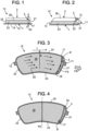
- a brake pad comprises a shoe 1 , also sometimes called a metal baseplate.
- the shoe is preferably made from metal material; it is formed like a constant full thickness pad (between 3 and 5mm typically). Its general facial form is rectangular, sometimes with a curve which follows the curve of the lateral face of the disc, whereon the pads will come to exert their force.
- the shoe 1 comprises an external face 14 intended to support the calliper and/or the piston 55 of the axle A2 and an internal face 13 , whereon the lining is attached.
- the brake pad also comprises a support body, also called a “brake lining” 2 comprising friction material, this material sometimes commonly called “Ferodo”.
- the lining 2 is likely to release particles 28 resulting from abrasion due to friction.
- the lining 2 is delimited by a friction face 26 ('rubbing' face), a mounting face 20 opposite the friction face and jointly attached to the shoe, an internal edge 23 (side of the axle A ), an external edge 24 (on the opposite side of the axle A ), a front edge 21 and a rear edge 22.
- the front edge 21 is located in a circumferential marker on the side of the disc where the disc emerges from the interface with the pad (side FW ).
- the rubbing face is identified 26 , it becomes progressively closer to the shoe as wear and tear of the lining 2 occurs in the direction of the shoe 1.
- the volume of the lining when new is represented as a dotted line, and as a continuous line, the volume after certain wear and tear.
- the thickness of the lining consequently decreases over time.
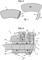
- the lining is provided with a collection groove 3 , open on the friction face 26 and arranged close to the front edge 21.
- the depth of the groove 3 corresponds the whole height of the groove, in other words, that the bottom of the groove corresponds to the internal surface area 13 of the shoe.
- an airflow FA is created in this collection groove 3 , this airflow being generated by suction coming from a vacuum source.
- the groove 3 emerges at the internal edge in an identified mouth 33 .
- the groove emerges at the external edge in an identified mouth 34 .
- the groove 3 ends by an identified blind end 31 , not emerging at the edge.
- the collection groove is unique and continuous, the collection groove is of a constant width and is substantially parallel to the front edge 21 .
- the lining comprises other grooves for the purpose of releasing water.
- the width E of the collection groove that is between 1.5mm and 4mm can be chosen, preferably near 2.5mm.
- a width E of the collection groove which can go from 2.5mm up to 6mm can be chosen.
- the groove width can be chosen, substantially proportionally to the total surface area of the lining.
- the collection groove 3 can be formed at the same time as the formation of the lining, or subsequently.
- the shoe 1 comprises two tenons or ears 11,12 which serve to hold and guide the brake pad. Each tenon is received by complementarity of form, in a housing of the calliper support 6 .
- the vehicle stops according to the tangential T and radial R directions, and the housing enables a movement of the tenon according to the axial direction A.
- the shoe comprises a hole 17 which is used as a passage for the suction of particles removed at the lining. Indeed, the shoe hole 17 emerges at the groove close to the blind end 31 , which again optimises the airflow to collect particles.
- the hole 17 in the shoe is positioned so that it is located in fluid communication with the collection groove, not necessarily close to the blind end 31 .
- the shoe comprises two holes, only one of which opposite the groove. In this case, there is only one single shoe reference, even if there are two separate pad references (see below).
- the hole 17 can have a diameter that is slightly more than the general width of the groove; however, the groove can have a larger width where the hole 17 is.
- the disc is of a constant thickness, interdependent of the wheel to brake (or the wheel axles to brake); the two runners 10A , 10B (also called 'brake pads') are intended to support the disc to brake it, using the action of the brake calliper 5 .
- the disc comprises a hub, a first annular lateral face, on the side of the calliper's piston, noted 9A perpendicular to the axle A, and a second annular face on the side of the wheel rim, noted 9B parallel to the first lateral face; the radially external edges of the lateral faces are connected by an edge called a disc edge 93 .
- the brake calliper 5 is attached by attaching to the calliper support 6 .
- this attachment is of the floating type according to A2, for example, with rods 56 (also called 'columns'), well known and therefore not detailed.
- the calliper support 6 comprises a tread intended to be attached to a suspending arm or a hub carrier, and attached U-shaped hinge-plates on the disc: more specifically, a first hinge-plate 61 on the front side, a second hinge-plate 62 on the rear side, and a connecting arc 63 which connects the hinge-plates opposite the tread.
- the tread is arranged on the internal side of the vehicle in relation to the disc 9 , and the connecting arc is arranged on the external side of the vehicle in relation to the disc 9.
- the tread is attached to the suspending arm or to the hub carried, as the case may be.
- the runners 10A , 10B are attached so that they can be moved according to A in relation to the calliper support 6 , but they are substantially immobilised in the circumferential direction T and in the radial direction R to the tenons 11, 12 and complementarities of forms already mentioned.
- the pad on the piston side in other words, opposite the wheel rim, is identified 10A , also the "bottom pad” is spoken of, it supports the first face 9A of the disc.
- the opposite identified pad 10B known as “external”, is on the side of the wheel rim, in other words, on the opposite side of the calliper's piston, it supports the second face 9B of the disc.
- the bottom pad 10A and the external pad 10B are different, because of the different configuration of their linings, but it is not excluded that for standardisation reasons, two symmetrical grooves are formed in relation to the median plane of the pad PS.
- the two pads are selectively requested, one in the direction of the other, to sandwich the disc 9 under the effect of the piston 55 , by thus producing a force PF directed according to A2 parallel to the axial wheel direction A.
- the calliper has a general U-shape attached to the disc and comprises a body 50 and fingers 51,52 arranged opposite the piston 55.
- the ratio K S3/S20 is defined.
- the ratio K ⁇ 5% can be advantageously had, or even preferably less than 4%.
- the remaining surface area S21 located below the collection groove represents less than 10% of S20.
- the suction device can be arranged in several ways.
- this suction device 8 comprises an electric motor, a filter, a turbine.
- this suction device comprises an electric motor, a filter, a turbine.
- the length of the pneumatic ducts is short, as short as possible to limit the loss of aeraulic loads.
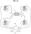
- this suction device 8 can be arranged centrally, as this is illustrated as a dotted line in figure 12 .
- Fluid communication means are provided (noted generically by the reference 4 ), in other words, for example, a pneumatic hose otherwise called pneumatic channelling, which fluidly connects the suction device with the two collection grooves.
- the communication means are formed by a flexible hose 40 of which one end is attached in the shoe hole 17 and the other end comes into the suction device.
- the flexible hose in question can be formed from one single part or several parts, in other words, with sections of hose, possibly with connectors.
- the configuration in figure 10 can be called upon, with a crossing passage 57, or the configuration in figure 11 without a crossing passage in the calliper.
- Figure 9 illustrates a solution for the attachment of the end of the flexible hose 40 in the shoe of the pad at the level of the hole 17 .
- the hole 17 can be formed by two coaxial axle bores A3 , this directed towards the lining being of a slightly larger diameter.
- the free end of the hose comprises flexible hook shapes 47 provided to cooperate with a shoulder formed where the two bores of different diameters to the hole 17 meet.
- the communication means 4 are formed by ducts or pneumatic channels of a small diameter.
- centralised suction device 80 with a filter, turbine and electric motor, as well as pneumatic channels 41,42,43,44, which respectively connect each one of the braking bodies to the central suction device.
- an electronic control unit 7 responsible for controlling the suction phases according to a predefined logic, in particular according to the different braking phases. Suction can thus be avoided, when no braking action is exercised by the driver and/or by the vehicle system.
- the electronic control unit 7 can be connected by cables 71,72,73,74 to the decentralised suction devices, located near the braking bodies.
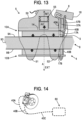
- figure 13 another variant of the invention has also been represented. Only the differences with the first embodiment and, in particular, the configuration in figure 6 will be explained.
- a first flexible hose of which one end is attached in a first hole 17A of the bottom pad 10A has been identified.
- a second flexible hose of which one end is attached in a second hole 17B of the external pad 10B has been identified.
- the first hose 40A passes through a first internal passage 57A arranged in the body of the calliper 5.
- the second hose 40B also passes through a second internal passage 57B arranged in the body of the calliper 5. This arrangement decreases the volume connected to the presence of the second hose 40B.
- the first 57A and second 57B passages are, of course, transversal.
- a brake unit comprising the brake disc 9, the brake calliper 5, two pads 10A, 10B and the suction device 8 connected to the grooves of the pads by the communication means 4.
- the pad 10A comprises a first hole 17A.
- the pad 10B comprises a second hole 17B.
- the communication means 4 comprise the first flexible hose 40A of which the end is fitted into the first hole 17A of the pad 10A.
- the communication means 4 also comprise the second flexible hose 40B of which the end is fitted into the second hole 17B of the pad 10B.
- first hose 40A is arranged in the first passage 57A of the calliper 5.
- the second hose 40B is arranged in the second passage 57B of the calliper 5.
- first 57A and second 57B passages can be separate, as in the configuration illustrated in figure 13 , but also only forming one single passage which receives the first 40A and second 40B flexible hoses.
- the second hose 40B can also be arranged in a collecting passage made on the disc 9.
- first 57A and second 57B passages of the calliper cannot comprise a flexible hose.
- the dust particles are sucked into these passages 57A and 57B without gaining any flexible hose.
- the second flexible hose 40B can be partially arranged in the collection groove 3B of the pad 10B.
- the first 40A and second 40B flexible hoses can be joined by their opposite ends to those respectively fitted into the first 17A and second 17B holes. They thus comprise a shared arm 40C which emerges at the suction device 80A.
- the unit formed by the first 17A and second 17B flexible hoses, as well as the shared arm 40C thus has a general "Y"-shape.
- this configuration has the advantage of limiting the volume of the braking unit according to the invention.
- the configuration in figure 14 can also be positioned with two hoses 40 according to the configuration in figure 6 .
Landscapes
- Engineering & Computer Science (AREA)
- General Engineering & Computer Science (AREA)
- Mechanical Engineering (AREA)
- Braking Arrangements (AREA)
Claims (10)
- Plaquette de frein dans un frein à disque d'axe A, la plaquette comprenant une semelle (1) et une garniture en matériau de friction, la garniture étant délimitée par une face de friction (26), une face de fixation (20), un bord intérieur (23), un bord extérieur (24), un bord avant (21), un bord arrière (22), la garniture étant pourvue d'une rainure de collecte (3) ouverte sur la face de friction (26) et agencée à proximité du bord avant (21), la semelle comprenant un trou (17) en communication fluide avec la rainure de collecte, ce trou pouvant être relié à une source de dépression via des moyens de communication (4), caractérisée en ce que la rainure de collecte débouche dans une embouchure repérée (33, 34) sur seulement l'un des bords choisi parmi les bords intérieur et extérieur, dans laquelle à l'opposé de ladite embouchure, la rainure de collecte (3) se termine par une extrémité borgne repérée (31), non débouchante sur le bord.
- Plaquette de frein selon la revendication 1, dans laquelle la rainure de collecte est creusée directement dans le matériau de friction, jusqu'à la surface de la semelle.
- Plaquette de frein selon la revendication 1, dans laquelle la rainure de collecte est formée directement dans le matériau de friction pendant l'opération de frittage, avec un fond de rainure qui coïncide avec la surface de la semelle.
- Plaquette de frein selon l'une des revendications 1 à 3, dans laquelle la surface S3
occupée par la rainure, est inférieure à 5 % de la surface totale disponible S20 sur la face de friction. - Plaquette de frein selon l'une des revendications 1 à 4, dans laquelle la rainure de collecte s'étend généralement radialement par rapport à l'axe A, entre ladite extrémité débouchante (33, 34) et ladite extrémité borgne (31), le trou (17) de la semelle débouchant dans la rainure à proximité de l'extrémité borgne.
- Plaquette de frein selon l'une des revendications 1 à 5, dans laquelle la rainure de collecte est unique et continue, et la rainure de collecte est de largeur constante et est substantiellement parallèle au bord avant de la garniture.
- Ensemble de frein comportant un disque de frein (9), un étrier de frein (5), deux plaquettes (10A,10B) selon l'une des revendications 1-8, et un dispositif d'aspiration (8) reliés pneumatiquement aux rainures des plaquettes par les moyens de communication (4).
- Ensemble de frein selon la revendication 7, dans lequel les moyens de communication (7) comprennent au moins un tuyau souple (40).
- Ensemble de frein selon la revendication 8, dans lequel une extrémité du tuyau souple est emmanchée dans un trou (17) de semelle.
- Ensemble de frein selon la revendication 7, dans lequel les moyens de communication sont formés au travers d'un passage (57) interne ménagé dans le corps (50) de l'étrier (5).
Applications Claiming Priority (2)
| Application Number | Priority Date | Filing Date | Title |
|---|---|---|---|
| FR1659613A FR3057040B1 (fr) | 2016-10-05 | 2016-10-05 | Plaquette de frein et ensemble de frein a captation de particules |
| PCT/EP2017/075401 WO2018065541A1 (fr) | 2016-10-05 | 2017-10-05 | Plaquette de frein et unité de freinage pour capturer des particules |
Publications (3)
| Publication Number | Publication Date |
|---|---|
| EP3523550A1 EP3523550A1 (fr) | 2019-08-14 |
| EP3523550B1 EP3523550B1 (fr) | 2020-09-09 |
| EP3523550B2 true EP3523550B2 (fr) | 2023-11-29 |
Family
ID=57906751
Family Applications (1)
| Application Number | Title | Priority Date | Filing Date |
|---|---|---|---|
| EP17780106.5A Active EP3523550B2 (fr) | 2016-10-05 | 2017-10-05 | Plaquette de frein et unité de freinage pour capturer des particules |
Country Status (10)
| Country | Link |
|---|---|
| US (1) | US10935092B2 (fr) |
| EP (1) | EP3523550B2 (fr) |
| JP (1) | JP6953522B2 (fr) |
| KR (1) | KR102526339B1 (fr) |
| CN (1) | CN109790889B (fr) |
| CA (1) | CA3038425A1 (fr) |
| FR (1) | FR3057040B1 (fr) |
| RU (1) | RU2729100C1 (fr) |
| SG (1) | SG11201902942XA (fr) |
| WO (1) | WO2018065541A1 (fr) |
Families Citing this family (29)
| Publication number | Priority date | Publication date | Assignee | Title |
|---|---|---|---|---|
| FR3069832B1 (fr) * | 2017-08-01 | 2019-09-06 | Tallano Technologie | Ensemble a friction pour systeme de freinage ferroviaire |
| FR3069831B1 (fr) * | 2017-08-01 | 2019-09-13 | Tallano Technologie | Ensemble a friction pour systeme de freinage ferroviaire |
| FR3076877B1 (fr) * | 2018-01-17 | 2020-01-03 | Tallano Technologie | Plaquette de frein a disque comprenant une rainure de collecte s'etendant en biais |
| FR3081037B1 (fr) * | 2018-05-09 | 2021-12-03 | Tallano Tech | Ensemble a friction pour systeme de frein a disques apte a filtrer une phase gazeuse issue de la friction d'une garniture |
| FR3087238B1 (fr) | 2018-10-12 | 2020-12-25 | Tallano Tech | Plaquette de frein avec collecte des particules et poussieres |
| FR3088395B1 (fr) | 2018-11-08 | 2020-11-20 | Tallano Tech | Systeme d'aspiration des particules de freinage a commande optimisee |
| FR3088393B1 (fr) | 2018-11-08 | 2020-12-11 | Tallano Tech | Systeme d'aspiration des particules de freinage a anticipation de commande |
| FR3088394B1 (fr) * | 2018-11-08 | 2020-11-20 | Tallano Tech | Systeme de captation de particules de frein a disque ferroviaire avec bague d'etancheite et mecanisme de rappel |
| FR3088392A1 (fr) | 2018-11-08 | 2020-05-15 | Tallano Technologie | Systeme d'aspiration des particules de freinage avec maintien de depression |
| FR3094428B1 (fr) | 2019-03-28 | 2021-04-16 | Tallano Tech | Système de freinage avec soufflage dans rainure de la garniture |
| FR3094429B1 (fr) | 2019-03-28 | 2021-04-16 | Tallano Tech | Système de freinage avec aspiration centrifuge dans rainure de la garniture |
| RU191317U1 (ru) * | 2019-05-27 | 2019-08-01 | Акционерное общество "Термостойкие изделия и инженерные разработки" (АО "ТИИР") | Колодка дискового тормоза |
| FR3098178B1 (fr) * | 2019-07-03 | 2021-07-30 | Tallano Tech | Système de sécurisation de pièce montée sur porte-semelle |
| DE102019213933A1 (de) * | 2019-09-12 | 2021-03-18 | Continental Teves Ag & Co. Ohg | System zum Auffangen von Abriebpartikeln einer Reibbremse |
| FR3107744B1 (fr) * | 2020-02-28 | 2022-03-18 | Tallano Tech | Détection de filtre dans un système de captation de particules de freinage |
| FR3107743B1 (fr) * | 2020-02-28 | 2024-03-29 | Tallano Tech | Limitation d’une machine par un système de captation de particules de freinage |
| FR3107656B1 (fr) * | 2020-02-28 | 2022-03-18 | Tallano Tech | Identification de filtre dans un système de captation de particules de freinage |
| DE102020107847A1 (de) | 2020-03-23 | 2021-09-23 | Knorr-Bremse Systeme für Schienenfahrzeuge GmbH | Bremsbelag |
| DE102020108533A1 (de) | 2020-03-27 | 2021-09-30 | Tallano Technologie | Scheibenbremsenbaugruppe mit Identifikationssystem |
| CN111503182A (zh) * | 2020-04-26 | 2020-08-07 | 上海第二工业大学 | 负压降温环保刹车片及负压环保刹车系统 |
| CN112628311B (zh) * | 2020-12-17 | 2023-01-03 | 山西江淮重工有限责任公司 | 偏航制动器 |
| FR3123398A1 (fr) | 2021-06-01 | 2022-12-02 | Tallano Technologie | Procédé d’aspiration des particules de freinage |
| DE102021126026A1 (de) | 2021-10-07 | 2023-04-13 | Knorr-Bremse Systeme für Nutzfahrzeuge GmbH | Scheibenbremse und Bremsbelag für eine Scheibenbremse |
| ES2910139B2 (es) * | 2022-03-01 | 2023-02-13 | Green Rk22 S L | Mecanismo de freno de disco con sistema de refrigeracion y de captacion de particulas derivadas de la friccion |
| ES2914247B2 (es) * | 2022-03-01 | 2023-01-05 | Green Rk22 S L | Fluido filtrante para retencion de particulas en suspension |
| FR3142787A1 (fr) * | 2022-12-02 | 2024-06-07 | Tallano Technologie | Perçage incliné d’entrée d’air |
| FR3145956A1 (fr) | 2023-02-21 | 2024-08-23 | Tallano Technologie | Dispositif de freinage a friction |
| FR3145955A1 (fr) | 2023-02-21 | 2024-08-23 | Tallano Technologie | Dispositif de freinage a friction |
| FR3145957A1 (fr) | 2023-02-21 | 2024-08-23 | Tallano Technologie | Dispositif de freinage a friction |
Citations (11)
| Publication number | Priority date | Publication date | Assignee | Title |
|---|---|---|---|---|
| DE3832199A1 (de) † | 1988-09-22 | 1990-03-29 | Bergische Stahlindustrie | Bremsbelaege |
| DE4401846A1 (de) † | 1994-01-22 | 1995-07-27 | Teves Gmbh Alfred | Bremsbelag für Scheibenbremse |
| DE19846887A1 (de) † | 1998-10-13 | 2000-04-20 | Wolfgang Foesel | Bremsanlage für ein Kraftfahrzeug |
| JP2007192268A (ja) † | 2006-01-18 | 2007-08-02 | Toyota Motor Corp | ディスクブレーキ装置およびブレーキパッド |
| CN101749346A (zh) † | 2008-12-09 | 2010-06-23 | 温芫鋐 | 煞车块结构 |
| WO2013084188A1 (fr) † | 2011-12-06 | 2013-06-13 | Mennie Trevor Michael | Ensemble garniture de frein |
| JP2013144585A (ja) † | 2012-01-13 | 2013-07-25 | Mitsubishi Electric Corp | エレベータ巻上機用のディスクブレーキ装置及び粉塵除去方法 |
| CN203202078U (zh) † | 2012-11-20 | 2013-09-18 | 北京天宜上佳新材料有限公司 | 一种新型燕尾结构合成闸片 |
| EP2698554A1 (fr) † | 2012-08-17 | 2014-02-19 | Bendix Spicer Foundation Brake LLC | Frein à disque |
| WO2017036802A1 (fr) † | 2015-08-31 | 2017-03-09 | Continental Teves Ag & Co. Ohg | Plaque dorsale pour une garniture de frein à disque, garniture de frein à disque et frein à disque à étrier fixe |
| WO2017106776A1 (fr) † | 2015-12-17 | 2017-06-22 | Federal-Mogul Motorparts Corporation | Garniture de friction et plaquette de frein pour un système de freinage |
Family Cites Families (23)
| Publication number | Priority date | Publication date | Assignee | Title |
|---|---|---|---|---|
| FR1322322A (fr) * | 1962-02-16 | 1963-03-29 | Ferodo Sa | Patin pour frein à disque, ses procédé et dispositif de fabrication |
| JPS5296189U (fr) * | 1976-01-19 | 1977-07-19 | ||
| US4135606A (en) * | 1977-05-02 | 1979-01-23 | Lewis Nathanial H | Capillary action brake shoe: vacuum suction type |
| JPS5942514Y2 (ja) * | 1979-07-19 | 1984-12-12 | トヨタ自動車株式会社 | 車両のブレ−キ摩擦部材摩耗粉の回収装置 |
| JPS5617428A (en) * | 1979-07-23 | 1981-02-19 | Canon Inc | Numeral input display unit of small size electronic computer |
| JPS58203238A (ja) * | 1982-04-20 | 1983-11-26 | Nippon Funmatsu Gokin Kk | ブレ−キパツド |
| JPS6016027U (ja) * | 1983-07-12 | 1985-02-02 | 本田技研工業株式会社 | デイスクブレ−キ装置 |
| JPS63215788A (ja) * | 1987-03-04 | 1988-09-08 | Akebono Brake Ind Co Ltd | 摩擦材の接着方法 |
| JPH08277866A (ja) * | 1995-04-04 | 1996-10-22 | Akebono Brake Ind Co Ltd | ブレーキパッド |
| KR100267658B1 (ko) * | 1996-12-31 | 2000-10-16 | 정몽규 | 브레이크 패드의 분진흡수장치 |
| JP2005036829A (ja) * | 2003-07-15 | 2005-02-10 | Mitsubishi Electric Corp | 摩擦式ブレーキ装置 |
| JP2005155657A (ja) * | 2003-11-20 | 2005-06-16 | Kranz:Kk | ディスクブレーキのブレーキパッド |
| JP2008281060A (ja) * | 2007-05-09 | 2008-11-20 | Toyota Motor Corp | ブレーキパッド |
| KR20130114854A (ko) * | 2012-04-10 | 2013-10-21 | 한국철도공사 | 마모한도부가 표시된 철도차량용 브레이크 라이닝 |
| PL225371B1 (pl) * | 2012-10-26 | 2017-04-28 | Przemysłowy Inst Motoryzacji | Urządzenie do redukcji emisji pyłów powstających podczas hamowania pojazdu wyposażonego w hamulec bębnowy |
| FR2997743B1 (fr) | 2012-11-08 | 2016-04-29 | Tallano Tech | Ensemble de frein a captation de particules |
| GB201507143D0 (en) * | 2014-12-17 | 2015-06-10 | Mennie Trevor M | Brake system |
| FR3034831B1 (fr) * | 2015-04-10 | 2018-04-27 | Romuald Jean Jacques Vigier | Dispositif antipollution pour frein a disque |
| CN105465250A (zh) * | 2016-01-14 | 2016-04-06 | 贵州大学 | 一种散热性较强的汽车盘式制动器摩擦衬块 |
| FR3054627B1 (fr) * | 2016-07-28 | 2019-04-26 | Renault S.A.S. | Plaquette de frein et systeme de freinage d'un vehicule automobile |
| FR3069832B1 (fr) * | 2017-08-01 | 2019-09-06 | Tallano Technologie | Ensemble a friction pour systeme de freinage ferroviaire |
| FR3071573B1 (fr) * | 2017-09-26 | 2019-09-27 | Psa Automobiles Sa | Plaquette de frein avec collecteur de poussieres |
| FR3076877B1 (fr) * | 2018-01-17 | 2020-01-03 | Tallano Technologie | Plaquette de frein a disque comprenant une rainure de collecte s'etendant en biais |
-
2016
- 2016-10-05 FR FR1659613A patent/FR3057040B1/fr active Active
-
2017
- 2017-10-05 KR KR1020197009722A patent/KR102526339B1/ko active IP Right Grant
- 2017-10-05 SG SG11201902942XA patent/SG11201902942XA/en unknown
- 2017-10-05 CN CN201780061733.8A patent/CN109790889B/zh active Active
- 2017-10-05 RU RU2019113331A patent/RU2729100C1/ru active
- 2017-10-05 WO PCT/EP2017/075401 patent/WO2018065541A1/fr unknown
- 2017-10-05 CA CA3038425A patent/CA3038425A1/fr active Pending
- 2017-10-05 US US16/339,739 patent/US10935092B2/en active Active
- 2017-10-05 JP JP2019518454A patent/JP6953522B2/ja active Active
- 2017-10-05 EP EP17780106.5A patent/EP3523550B2/fr active Active
Patent Citations (11)
| Publication number | Priority date | Publication date | Assignee | Title |
|---|---|---|---|---|
| DE3832199A1 (de) † | 1988-09-22 | 1990-03-29 | Bergische Stahlindustrie | Bremsbelaege |
| DE4401846A1 (de) † | 1994-01-22 | 1995-07-27 | Teves Gmbh Alfred | Bremsbelag für Scheibenbremse |
| DE19846887A1 (de) † | 1998-10-13 | 2000-04-20 | Wolfgang Foesel | Bremsanlage für ein Kraftfahrzeug |
| JP2007192268A (ja) † | 2006-01-18 | 2007-08-02 | Toyota Motor Corp | ディスクブレーキ装置およびブレーキパッド |
| CN101749346A (zh) † | 2008-12-09 | 2010-06-23 | 温芫鋐 | 煞车块结构 |
| WO2013084188A1 (fr) † | 2011-12-06 | 2013-06-13 | Mennie Trevor Michael | Ensemble garniture de frein |
| JP2013144585A (ja) † | 2012-01-13 | 2013-07-25 | Mitsubishi Electric Corp | エレベータ巻上機用のディスクブレーキ装置及び粉塵除去方法 |
| EP2698554A1 (fr) † | 2012-08-17 | 2014-02-19 | Bendix Spicer Foundation Brake LLC | Frein à disque |
| CN203202078U (zh) † | 2012-11-20 | 2013-09-18 | 北京天宜上佳新材料有限公司 | 一种新型燕尾结构合成闸片 |
| WO2017036802A1 (fr) † | 2015-08-31 | 2017-03-09 | Continental Teves Ag & Co. Ohg | Plaque dorsale pour une garniture de frein à disque, garniture de frein à disque et frein à disque à étrier fixe |
| WO2017106776A1 (fr) † | 2015-12-17 | 2017-06-22 | Federal-Mogul Motorparts Corporation | Garniture de friction et plaquette de frein pour un système de freinage |
Also Published As
| Publication number | Publication date |
|---|---|
| EP3523550A1 (fr) | 2019-08-14 |
| CA3038425A1 (fr) | 2018-04-12 |
| US20200049213A1 (en) | 2020-02-13 |
| JP6953522B2 (ja) | 2021-10-27 |
| KR20190091258A (ko) | 2019-08-05 |
| WO2018065541A1 (fr) | 2018-04-12 |
| US10935092B2 (en) | 2021-03-02 |
| EP3523550B1 (fr) | 2020-09-09 |
| KR102526339B1 (ko) | 2023-04-27 |
| SG11201902942XA (en) | 2019-05-30 |
| FR3057040A1 (fr) | 2018-04-06 |
| CN109790889B (zh) | 2021-12-31 |
| FR3057040B1 (fr) | 2019-05-03 |
| JP2019529840A (ja) | 2019-10-17 |
| CN109790889A (zh) | 2019-05-21 |
| RU2729100C1 (ru) | 2020-08-04 |
Similar Documents
| Publication | Publication Date | Title |
|---|---|---|
| EP3523550B2 (fr) | Plaquette de frein et unité de freinage pour capturer des particules | |
| US20170198772A1 (en) | Particle Trapping Brake Assembly With Deflector | |
| JP7148168B2 (ja) | 鉄道ブレーキングシステムのための摩擦セット | |
| US20150122601A1 (en) | Brake Assembly with Particle Capture | |
| US20150001013A1 (en) | Brake pad assembly | |
| WO2014072234A2 (fr) | Ensemble de frein avec capture de particules | |
| WO2017073574A1 (fr) | Dispositif de frein à disque | |
| JP6902538B2 (ja) | ディスクブレーキのキャリパー本体 | |
| US7703779B2 (en) | Spindle cooling device | |
| CN111108300B (zh) | 用于铁路制动系统的摩擦装置 | |
| JP2021511469A (ja) | 前部領域における吸引溝と面取りされた前部領域を備えるディスクブレーキアセンブリのブレーキパッド | |
| KR20200105924A (ko) | 비스듬히 연장하는 수집 그루브를 구비하는 디스크 브레이크 패드 | |
| CN102371846B (zh) | 转向桥 | |
| CA2641504C (fr) | Systemes de freinage avec refroidissement | |
| CN201963772U (zh) | 纯盘式机械驻车制动器 | |
| CN104196931A (zh) | 锻造分体式制动钳 | |
| CN101708712A (zh) | 大速比矿用车驱动前桥 | |
| JP6660216B2 (ja) | ブレーキ支持部材及びこれを備えるブレーキ装置 | |
| JP2007309431A (ja) | ディスクブレーキ装置 | |
| CN113879043A (zh) | 具防锁死剎车系统的轮毂结构 |
Legal Events
| Date | Code | Title | Description |
|---|---|---|---|
| STAA | Information on the status of an ep patent application or granted ep patent |
Free format text: STATUS: UNKNOWN |
|
| STAA | Information on the status of an ep patent application or granted ep patent |
Free format text: STATUS: THE INTERNATIONAL PUBLICATION HAS BEEN MADE |
|
| PUAI | Public reference made under article 153(3) epc to a published international application that has entered the european phase |
Free format text: ORIGINAL CODE: 0009012 |
|
| STAA | Information on the status of an ep patent application or granted ep patent |
Free format text: STATUS: REQUEST FOR EXAMINATION WAS MADE |
|
| 17P | Request for examination filed |
Effective date: 20190416 |
|
| AK | Designated contracting states |
Kind code of ref document: A1 Designated state(s): AL AT BE BG CH CY CZ DE DK EE ES FI FR GB GR HR HU IE IS IT LI LT LU LV MC MK MT NL NO PL PT RO RS SE SI SK SM TR |
|
| AX | Request for extension of the european patent |
Extension state: BA ME |
|
| DAV | Request for validation of the european patent (deleted) | ||
| DAX | Request for extension of the european patent (deleted) | ||
| GRAP | Despatch of communication of intention to grant a patent |
Free format text: ORIGINAL CODE: EPIDOSNIGR1 |
|
| STAA | Information on the status of an ep patent application or granted ep patent |
Free format text: STATUS: GRANT OF PATENT IS INTENDED |
|
| INTG | Intention to grant announced |
Effective date: 20200424 |
|
| GRAS | Grant fee paid |
Free format text: ORIGINAL CODE: EPIDOSNIGR3 |
|
| GRAA | (expected) grant |
Free format text: ORIGINAL CODE: 0009210 |
|
| STAA | Information on the status of an ep patent application or granted ep patent |
Free format text: STATUS: THE PATENT HAS BEEN GRANTED |
|
| AK | Designated contracting states |
Kind code of ref document: B1 Designated state(s): AL AT BE BG CH CY CZ DE DK EE ES FI FR GB GR HR HU IE IS IT LI LT LU LV MC MK MT NL NO PL PT RO RS SE SI SK SM TR |
|
| REG | Reference to a national code |
Ref country code: GB Ref legal event code: FG4D |
|
| REG | Reference to a national code |
Ref country code: AT Ref legal event code: REF Ref document number: 1311958 Country of ref document: AT Kind code of ref document: T Effective date: 20200915 Ref country code: CH Ref legal event code: EP |
|
| REG | Reference to a national code |
Ref country code: IE Ref legal event code: FG4D |
|
| REG | Reference to a national code |
Ref country code: DE Ref legal event code: R096 Ref document number: 602017023411 Country of ref document: DE |
|
| REG | Reference to a national code |
Ref country code: LT Ref legal event code: MG4D |
|
| PG25 | Lapsed in a contracting state [announced via postgrant information from national office to epo] |
Ref country code: BG Free format text: LAPSE BECAUSE OF FAILURE TO SUBMIT A TRANSLATION OF THE DESCRIPTION OR TO PAY THE FEE WITHIN THE PRESCRIBED TIME-LIMIT Effective date: 20201209 Ref country code: SE Free format text: LAPSE BECAUSE OF FAILURE TO SUBMIT A TRANSLATION OF THE DESCRIPTION OR TO PAY THE FEE WITHIN THE PRESCRIBED TIME-LIMIT Effective date: 20200909 Ref country code: LT Free format text: LAPSE BECAUSE OF FAILURE TO SUBMIT A TRANSLATION OF THE DESCRIPTION OR TO PAY THE FEE WITHIN THE PRESCRIBED TIME-LIMIT Effective date: 20200909 Ref country code: HR Free format text: LAPSE BECAUSE OF FAILURE TO SUBMIT A TRANSLATION OF THE DESCRIPTION OR TO PAY THE FEE WITHIN THE PRESCRIBED TIME-LIMIT Effective date: 20200909 Ref country code: GR Free format text: LAPSE BECAUSE OF FAILURE TO SUBMIT A TRANSLATION OF THE DESCRIPTION OR TO PAY THE FEE WITHIN THE PRESCRIBED TIME-LIMIT Effective date: 20201210 Ref country code: FI Free format text: LAPSE BECAUSE OF FAILURE TO SUBMIT A TRANSLATION OF THE DESCRIPTION OR TO PAY THE FEE WITHIN THE PRESCRIBED TIME-LIMIT Effective date: 20200909 Ref country code: NO Free format text: LAPSE BECAUSE OF FAILURE TO SUBMIT A TRANSLATION OF THE DESCRIPTION OR TO PAY THE FEE WITHIN THE PRESCRIBED TIME-LIMIT Effective date: 20201209 |
|
| REG | Reference to a national code |
Ref country code: AT Ref legal event code: MK05 Ref document number: 1311958 Country of ref document: AT Kind code of ref document: T Effective date: 20200909 |
|
| REG | Reference to a national code |
Ref country code: NL Ref legal event code: MP Effective date: 20200909 |
|
| PG25 | Lapsed in a contracting state [announced via postgrant information from national office to epo] |
Ref country code: RS Free format text: LAPSE BECAUSE OF FAILURE TO SUBMIT A TRANSLATION OF THE DESCRIPTION OR TO PAY THE FEE WITHIN THE PRESCRIBED TIME-LIMIT Effective date: 20200909 Ref country code: PL Free format text: LAPSE BECAUSE OF FAILURE TO SUBMIT A TRANSLATION OF THE DESCRIPTION OR TO PAY THE FEE WITHIN THE PRESCRIBED TIME-LIMIT Effective date: 20200909 Ref country code: LV Free format text: LAPSE BECAUSE OF FAILURE TO SUBMIT A TRANSLATION OF THE DESCRIPTION OR TO PAY THE FEE WITHIN THE PRESCRIBED TIME-LIMIT Effective date: 20200909 |
|
| PG25 | Lapsed in a contracting state [announced via postgrant information from national office to epo] |
Ref country code: CZ Free format text: LAPSE BECAUSE OF FAILURE TO SUBMIT A TRANSLATION OF THE DESCRIPTION OR TO PAY THE FEE WITHIN THE PRESCRIBED TIME-LIMIT Effective date: 20200909 Ref country code: PT Free format text: LAPSE BECAUSE OF FAILURE TO SUBMIT A TRANSLATION OF THE DESCRIPTION OR TO PAY THE FEE WITHIN THE PRESCRIBED TIME-LIMIT Effective date: 20210111 Ref country code: RO Free format text: LAPSE BECAUSE OF FAILURE TO SUBMIT A TRANSLATION OF THE DESCRIPTION OR TO PAY THE FEE WITHIN THE PRESCRIBED TIME-LIMIT Effective date: 20200909 Ref country code: EE Free format text: LAPSE BECAUSE OF FAILURE TO SUBMIT A TRANSLATION OF THE DESCRIPTION OR TO PAY THE FEE WITHIN THE PRESCRIBED TIME-LIMIT Effective date: 20200909 Ref country code: SM Free format text: LAPSE BECAUSE OF FAILURE TO SUBMIT A TRANSLATION OF THE DESCRIPTION OR TO PAY THE FEE WITHIN THE PRESCRIBED TIME-LIMIT Effective date: 20200909 |
|
| PG25 | Lapsed in a contracting state [announced via postgrant information from national office to epo] |
Ref country code: AL Free format text: LAPSE BECAUSE OF FAILURE TO SUBMIT A TRANSLATION OF THE DESCRIPTION OR TO PAY THE FEE WITHIN THE PRESCRIBED TIME-LIMIT Effective date: 20200909 Ref country code: AT Free format text: LAPSE BECAUSE OF FAILURE TO SUBMIT A TRANSLATION OF THE DESCRIPTION OR TO PAY THE FEE WITHIN THE PRESCRIBED TIME-LIMIT Effective date: 20200909 Ref country code: ES Free format text: LAPSE BECAUSE OF FAILURE TO SUBMIT A TRANSLATION OF THE DESCRIPTION OR TO PAY THE FEE WITHIN THE PRESCRIBED TIME-LIMIT Effective date: 20200909 Ref country code: IS Free format text: LAPSE BECAUSE OF FAILURE TO SUBMIT A TRANSLATION OF THE DESCRIPTION OR TO PAY THE FEE WITHIN THE PRESCRIBED TIME-LIMIT Effective date: 20210109 |
|
| REG | Reference to a national code |
Ref country code: CH Ref legal event code: PL |
|
| REG | Reference to a national code |
Ref country code: DE Ref legal event code: R026 Ref document number: 602017023411 Country of ref document: DE |
|
| PLBI | Opposition filed |
Free format text: ORIGINAL CODE: 0009260 |
|
| PLAX | Notice of opposition and request to file observation + time limit sent |
Free format text: ORIGINAL CODE: EPIDOSNOBS2 |
|
| PG25 | Lapsed in a contracting state [announced via postgrant information from national office to epo] |
Ref country code: MC Free format text: LAPSE BECAUSE OF FAILURE TO SUBMIT A TRANSLATION OF THE DESCRIPTION OR TO PAY THE FEE WITHIN THE PRESCRIBED TIME-LIMIT Effective date: 20200909 Ref country code: LU Free format text: LAPSE BECAUSE OF NON-PAYMENT OF DUE FEES Effective date: 20201005 Ref country code: SK Free format text: LAPSE BECAUSE OF FAILURE TO SUBMIT A TRANSLATION OF THE DESCRIPTION OR TO PAY THE FEE WITHIN THE PRESCRIBED TIME-LIMIT Effective date: 20200909 |
|
| 26 | Opposition filed |
Opponent name: VRI-VERBAND DER REIBBELAGINDUSTRIE E.V. Effective date: 20210608 |
|
| REG | Reference to a national code |
Ref country code: BE Ref legal event code: MM Effective date: 20201031 |
|
| PG25 | Lapsed in a contracting state [announced via postgrant information from national office to epo] |
Ref country code: SI Free format text: LAPSE BECAUSE OF FAILURE TO SUBMIT A TRANSLATION OF THE DESCRIPTION OR TO PAY THE FEE WITHIN THE PRESCRIBED TIME-LIMIT Effective date: 20200909 Ref country code: DK Free format text: LAPSE BECAUSE OF FAILURE TO SUBMIT A TRANSLATION OF THE DESCRIPTION OR TO PAY THE FEE WITHIN THE PRESCRIBED TIME-LIMIT Effective date: 20200909 Ref country code: LI Free format text: LAPSE BECAUSE OF NON-PAYMENT OF DUE FEES Effective date: 20201031 Ref country code: BE Free format text: LAPSE BECAUSE OF NON-PAYMENT OF DUE FEES Effective date: 20201031 Ref country code: CH Free format text: LAPSE BECAUSE OF NON-PAYMENT OF DUE FEES Effective date: 20201031 |
|
| PLBB | Reply of patent proprietor to notice(s) of opposition received |
Free format text: ORIGINAL CODE: EPIDOSNOBS3 |
|
| PG25 | Lapsed in a contracting state [announced via postgrant information from national office to epo] |
Ref country code: IE Free format text: LAPSE BECAUSE OF NON-PAYMENT OF DUE FEES Effective date: 20201005 |
|
| PG25 | Lapsed in a contracting state [announced via postgrant information from national office to epo] |
Ref country code: TR Free format text: LAPSE BECAUSE OF FAILURE TO SUBMIT A TRANSLATION OF THE DESCRIPTION OR TO PAY THE FEE WITHIN THE PRESCRIBED TIME-LIMIT Effective date: 20200909 Ref country code: MT Free format text: LAPSE BECAUSE OF FAILURE TO SUBMIT A TRANSLATION OF THE DESCRIPTION OR TO PAY THE FEE WITHIN THE PRESCRIBED TIME-LIMIT Effective date: 20200909 Ref country code: CY Free format text: LAPSE BECAUSE OF FAILURE TO SUBMIT A TRANSLATION OF THE DESCRIPTION OR TO PAY THE FEE WITHIN THE PRESCRIBED TIME-LIMIT Effective date: 20200909 |
|
| PG25 | Lapsed in a contracting state [announced via postgrant information from national office to epo] |
Ref country code: MK Free format text: LAPSE BECAUSE OF FAILURE TO SUBMIT A TRANSLATION OF THE DESCRIPTION OR TO PAY THE FEE WITHIN THE PRESCRIBED TIME-LIMIT Effective date: 20200909 |
|
| PG25 | Lapsed in a contracting state [announced via postgrant information from national office to epo] |
Ref country code: NL Free format text: LAPSE BECAUSE OF NON-PAYMENT OF DUE FEES Effective date: 20200923 |
|
| P01 | Opt-out of the competence of the unified patent court (upc) registered |
Effective date: 20230530 |
|
| PUAH | Patent maintained in amended form |
Free format text: ORIGINAL CODE: 0009272 |
|
| STAA | Information on the status of an ep patent application or granted ep patent |
Free format text: STATUS: PATENT MAINTAINED AS AMENDED |
|
| 27A | Patent maintained in amended form |
Effective date: 20231129 |
|
| AK | Designated contracting states |
Kind code of ref document: B2 Designated state(s): AL AT BE BG CH CY CZ DE DK EE ES FI FR GB GR HR HU IE IS IT LI LT LU LV MC MK MT NL NO PL PT RO RS SE SI SK SM TR |
|
| REG | Reference to a national code |
Ref country code: DE Ref legal event code: R102 Ref document number: 602017023411 Country of ref document: DE |
|
| PGFP | Annual fee paid to national office [announced via postgrant information from national office to epo] |
Ref country code: FR Payment date: 20230921 Year of fee payment: 7 |
|
| PGFP | Annual fee paid to national office [announced via postgrant information from national office to epo] |
Ref country code: GB Payment date: 20231019 Year of fee payment: 7 |
|
| PGFP | Annual fee paid to national office [announced via postgrant information from national office to epo] |
Ref country code: IT Payment date: 20231010 Year of fee payment: 7 Ref country code: DE Payment date: 20231011 Year of fee payment: 7 |