EP3522252B1 - Montierte batterie - Google Patents
Montierte batterie Download PDFInfo
- Publication number
- EP3522252B1 EP3522252B1 EP17855435.8A EP17855435A EP3522252B1 EP 3522252 B1 EP3522252 B1 EP 3522252B1 EP 17855435 A EP17855435 A EP 17855435A EP 3522252 B1 EP3522252 B1 EP 3522252B1
- Authority
- EP
- European Patent Office
- Prior art keywords
- assembled battery
- fixing part
- cell
- plate
- holder
- Prior art date
- Legal status (The legal status is an assumption and is not a legal conclusion. Google has not performed a legal analysis and makes no representation as to the accuracy of the status listed.)
- Active
Links
Images


Classifications
-
- H—ELECTRICITY
- H01—ELECTRIC ELEMENTS
- H01M—PROCESSES OR MEANS, e.g. BATTERIES, FOR THE DIRECT CONVERSION OF CHEMICAL ENERGY INTO ELECTRICAL ENERGY
- H01M50/00—Constructional details or processes of manufacture of the non-active parts of electrochemical cells other than fuel cells, e.g. hybrid cells
- H01M50/10—Primary casings; Jackets or wrappings
- H01M50/172—Arrangements of electric connectors penetrating the casing
- H01M50/174—Arrangements of electric connectors penetrating the casing adapted for the shape of the cells
- H01M50/176—Arrangements of electric connectors penetrating the casing adapted for the shape of the cells for prismatic or rectangular cells
-
- H—ELECTRICITY
- H01—ELECTRIC ELEMENTS
- H01M—PROCESSES OR MEANS, e.g. BATTERIES, FOR THE DIRECT CONVERSION OF CHEMICAL ENERGY INTO ELECTRICAL ENERGY
- H01M50/00—Constructional details or processes of manufacture of the non-active parts of electrochemical cells other than fuel cells, e.g. hybrid cells
- H01M50/20—Mountings; Secondary casings or frames; Racks, modules or packs; Suspension devices; Shock absorbers; Transport or carrying devices; Holders
- H01M50/204—Racks, modules or packs for multiple batteries or multiple cells
- H01M50/207—Racks, modules or packs for multiple batteries or multiple cells characterised by their shape
- H01M50/209—Racks, modules or packs for multiple batteries or multiple cells characterised by their shape adapted for prismatic or rectangular cells
-
- H—ELECTRICITY
- H01—ELECTRIC ELEMENTS
- H01M—PROCESSES OR MEANS, e.g. BATTERIES, FOR THE DIRECT CONVERSION OF CHEMICAL ENERGY INTO ELECTRICAL ENERGY
- H01M50/00—Constructional details or processes of manufacture of the non-active parts of electrochemical cells other than fuel cells, e.g. hybrid cells
- H01M50/20—Mountings; Secondary casings or frames; Racks, modules or packs; Suspension devices; Shock absorbers; Transport or carrying devices; Holders
- H01M50/218—Mountings; Secondary casings or frames; Racks, modules or packs; Suspension devices; Shock absorbers; Transport or carrying devices; Holders characterised by the material
- H01M50/22—Mountings; Secondary casings or frames; Racks, modules or packs; Suspension devices; Shock absorbers; Transport or carrying devices; Holders characterised by the material of the casings or racks
- H01M50/222—Inorganic material
- H01M50/224—Metals
-
- H—ELECTRICITY
- H01—ELECTRIC ELEMENTS
- H01M—PROCESSES OR MEANS, e.g. BATTERIES, FOR THE DIRECT CONVERSION OF CHEMICAL ENERGY INTO ELECTRICAL ENERGY
- H01M50/00—Constructional details or processes of manufacture of the non-active parts of electrochemical cells other than fuel cells, e.g. hybrid cells
- H01M50/20—Mountings; Secondary casings or frames; Racks, modules or packs; Suspension devices; Shock absorbers; Transport or carrying devices; Holders
- H01M50/218—Mountings; Secondary casings or frames; Racks, modules or packs; Suspension devices; Shock absorbers; Transport or carrying devices; Holders characterised by the material
- H01M50/22—Mountings; Secondary casings or frames; Racks, modules or packs; Suspension devices; Shock absorbers; Transport or carrying devices; Holders characterised by the material of the casings or racks
- H01M50/229—Composite material consisting of a mixture of organic and inorganic materials
-
- H—ELECTRICITY
- H01—ELECTRIC ELEMENTS
- H01M—PROCESSES OR MEANS, e.g. BATTERIES, FOR THE DIRECT CONVERSION OF CHEMICAL ENERGY INTO ELECTRICAL ENERGY
- H01M50/00—Constructional details or processes of manufacture of the non-active parts of electrochemical cells other than fuel cells, e.g. hybrid cells
- H01M50/20—Mountings; Secondary casings or frames; Racks, modules or packs; Suspension devices; Shock absorbers; Transport or carrying devices; Holders
- H01M50/262—Mountings; Secondary casings or frames; Racks, modules or packs; Suspension devices; Shock absorbers; Transport or carrying devices; Holders with fastening means, e.g. locks
-
- H—ELECTRICITY
- H01—ELECTRIC ELEMENTS
- H01M—PROCESSES OR MEANS, e.g. BATTERIES, FOR THE DIRECT CONVERSION OF CHEMICAL ENERGY INTO ELECTRICAL ENERGY
- H01M50/00—Constructional details or processes of manufacture of the non-active parts of electrochemical cells other than fuel cells, e.g. hybrid cells
- H01M50/20—Mountings; Secondary casings or frames; Racks, modules or packs; Suspension devices; Shock absorbers; Transport or carrying devices; Holders
- H01M50/289—Mountings; Secondary casings or frames; Racks, modules or packs; Suspension devices; Shock absorbers; Transport or carrying devices; Holders characterised by spacing elements or positioning means within frames, racks or packs
- H01M50/291—Mountings; Secondary casings or frames; Racks, modules or packs; Suspension devices; Shock absorbers; Transport or carrying devices; Holders characterised by spacing elements or positioning means within frames, racks or packs characterised by their shape
-
- H—ELECTRICITY
- H01—ELECTRIC ELEMENTS
- H01M—PROCESSES OR MEANS, e.g. BATTERIES, FOR THE DIRECT CONVERSION OF CHEMICAL ENERGY INTO ELECTRICAL ENERGY
- H01M50/00—Constructional details or processes of manufacture of the non-active parts of electrochemical cells other than fuel cells, e.g. hybrid cells
- H01M50/20—Mountings; Secondary casings or frames; Racks, modules or packs; Suspension devices; Shock absorbers; Transport or carrying devices; Holders
- H01M50/296—Mountings; Secondary casings or frames; Racks, modules or packs; Suspension devices; Shock absorbers; Transport or carrying devices; Holders characterised by terminals of battery packs
-
- H—ELECTRICITY
- H01—ELECTRIC ELEMENTS
- H01M—PROCESSES OR MEANS, e.g. BATTERIES, FOR THE DIRECT CONVERSION OF CHEMICAL ENERGY INTO ELECTRICAL ENERGY
- H01M50/00—Constructional details or processes of manufacture of the non-active parts of electrochemical cells other than fuel cells, e.g. hybrid cells
- H01M50/50—Current conducting connections for cells or batteries
- H01M50/502—Interconnectors for connecting terminals of adjacent batteries; Interconnectors for connecting cells outside a battery casing
- H01M50/507—Interconnectors for connecting terminals of adjacent batteries; Interconnectors for connecting cells outside a battery casing comprising an arrangement of two or more busbars within a container structure, e.g. busbar modules
-
- H—ELECTRICITY
- H01—ELECTRIC ELEMENTS
- H01M—PROCESSES OR MEANS, e.g. BATTERIES, FOR THE DIRECT CONVERSION OF CHEMICAL ENERGY INTO ELECTRICAL ENERGY
- H01M50/00—Constructional details or processes of manufacture of the non-active parts of electrochemical cells other than fuel cells, e.g. hybrid cells
- H01M50/50—Current conducting connections for cells or batteries
- H01M50/502—Interconnectors for connecting terminals of adjacent batteries; Interconnectors for connecting cells outside a battery casing
- H01M50/509—Interconnectors for connecting terminals of adjacent batteries; Interconnectors for connecting cells outside a battery casing characterised by the type of connection, e.g. mixed connections
- H01M50/51—Connection only in series
-
- H—ELECTRICITY
- H01—ELECTRIC ELEMENTS
- H01M—PROCESSES OR MEANS, e.g. BATTERIES, FOR THE DIRECT CONVERSION OF CHEMICAL ENERGY INTO ELECTRICAL ENERGY
- H01M50/00—Constructional details or processes of manufacture of the non-active parts of electrochemical cells other than fuel cells, e.g. hybrid cells
- H01M50/50—Current conducting connections for cells or batteries
- H01M50/502—Interconnectors for connecting terminals of adjacent batteries; Interconnectors for connecting cells outside a battery casing
- H01M50/521—Interconnectors for connecting terminals of adjacent batteries; Interconnectors for connecting cells outside a battery casing characterised by the material
- H01M50/522—Inorganic material
-
- H—ELECTRICITY
- H01—ELECTRIC ELEMENTS
- H01M—PROCESSES OR MEANS, e.g. BATTERIES, FOR THE DIRECT CONVERSION OF CHEMICAL ENERGY INTO ELECTRICAL ENERGY
- H01M50/00—Constructional details or processes of manufacture of the non-active parts of electrochemical cells other than fuel cells, e.g. hybrid cells
- H01M50/50—Current conducting connections for cells or batteries
- H01M50/543—Terminals
- H01M50/547—Terminals characterised by the disposition of the terminals on the cells
- H01M50/55—Terminals characterised by the disposition of the terminals on the cells on the same side of the cell
-
- H—ELECTRICITY
- H01—ELECTRIC ELEMENTS
- H01M—PROCESSES OR MEANS, e.g. BATTERIES, FOR THE DIRECT CONVERSION OF CHEMICAL ENERGY INTO ELECTRICAL ENERGY
- H01M50/00—Constructional details or processes of manufacture of the non-active parts of electrochemical cells other than fuel cells, e.g. hybrid cells
- H01M50/50—Current conducting connections for cells or batteries
- H01M50/543—Terminals
- H01M50/552—Terminals characterised by their shape
- H01M50/553—Terminals adapted for prismatic, pouch or rectangular cells
-
- Y—GENERAL TAGGING OF NEW TECHNOLOGICAL DEVELOPMENTS; GENERAL TAGGING OF CROSS-SECTIONAL TECHNOLOGIES SPANNING OVER SEVERAL SECTIONS OF THE IPC; TECHNICAL SUBJECTS COVERED BY FORMER USPC CROSS-REFERENCE ART COLLECTIONS [XRACs] AND DIGESTS
- Y02—TECHNOLOGIES OR APPLICATIONS FOR MITIGATION OR ADAPTATION AGAINST CLIMATE CHANGE
- Y02E—REDUCTION OF GREENHOUSE GAS [GHG] EMISSIONS, RELATED TO ENERGY GENERATION, TRANSMISSION OR DISTRIBUTION
- Y02E60/00—Enabling technologies; Technologies with a potential or indirect contribution to GHG emissions mitigation
- Y02E60/10—Energy storage using batteries
Definitions
- the present invention relates to an assembled battery including multiple rechargeable batteries which can be recharged and discharged repeatedly and are connected to each other.
- an electrode terminal of a unit cell may be damaged by the fastening torque of connection when an external terminal cable is directly connected to a positive electrode terminal or a negative electrode terminal of the unit cell included in the assembled battery
- a method is adopted in which a busbar is provided at an electrode terminal of the unit cell and the busbar and the external terminal cable are bolted to each other at a fixing part provided separately from the electrode terminal of the unit cell.
- the fixing part receives a force in the rotational direction with respect to the axis of the bolt.
- the fixing part rotates by the force in the rotation direction, the fastening force of the bolt cannot be sufficient, and thus the magnitude of the fastening force of the bolt is dependent on the strength of the fixing part.
- a battery module has a battery body in which a plurality of battery cells held by a battery holder are arranged side by side, and in the battery body, an end plate is provided at both ends of the battery cells in the side by side arrangement direction. Further, an inclusion is interposed between at least one of the end plates and the battery cells adjacent to the end plate, and the battery holder has a facing portion that faces the inclusion.
- PTL 1 discloses a structure in which a fixing part is integrated with an end plate made of resin.
- a fixing part is applied with a force in a rotational direction for fastening a busbar and an external terminal cable; however when the fixing part is subjected to this force and thereby deformed, the fastening force cannot be secured, and thus the fastening force is dependent on the strength of the fixing part.
- a fixing part and an end plate are integrated to downsize the assembled battery. However, since the fastening force is received only by the strength of the member made of resin, there still remains a challenge for the fastening force.
- the present invention has been made in view of the above problem, and it is an object of the present invention to provide an assembled battery in which the fastening force between a busbar and an external terminal cable at a fixing part is improved while downsizing the assembled battery.
- the present invention provides an assembled battery according to claim 1.
- Dependent claims refer to preferred embodiments of the present invention.
- the present invention it is possible to lower the height of the assembled battery by lowering the position of the fixing part having a certain volume toward a bottom of a can and to further reduce the length in the longitudinal direction of the assembled battery by utilizing the thickness of the end plates to accommodate the volume of the fixing parts. These together allow the assembled battery to be downsized.
- allowing the fitting parts of the plate-shaped members to surround the terminal fixing parts of the cell holders allows the end plates to receive the force in the rotational direction applied to the fixing parts, thereby enabling an increase in the strength of the fixing parts and improvement of the fastening force between a busbar and an external terminal cable at the fixing part.
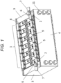
- FIG. 1 is an external perspective view of an assembled battery according to a first embodiment of the present invention.
- FIG. 2 is an exploded external perspective view of the assembled battery of FIG. 1 . Note that FIG. 2 is partially omitted.
- a cell stack 1 is sandwiched between a pair of end holders 2 and between a pair of end plates 3 which are plate-shaped members, which are all integrated with a pair of side frames 4, with intermediate busbars 5 forming a power line among cells and end busbars 6 and external terminal cables 7 forming a power line between the assembled battery and the outside thereof.
- the cell stack will be described with reference to FIGS. 1 and 2 .
- the cell stack 1 includes a plurality of unit cells 8 and the plurality of intermediate holders 9.
- Each of the unit cells has a flat rectangular parallelepiped shape and has a pair of wide surfaces.
- the plurality of unit cells included in the cell stack is stacked and arranged such that wide surfaces of adjacent unit cells face each other. Adjacent unit cells are arranged in reversed directions such that positions of a positive electrode terminal and a negative electrode terminal provided on each cell lid are reversed.
- Each pair of a positive electrode terminal and a negative electrode terminal of adjacent unit cells is electrically connected by an intermediate busbar 5 which is a flat conductive member made of metal. That is, the plurality of unit cells included in the assembled battery according to the present embodiment is electrically connected in series.
- an end busbar 6 is provided at a positive electrode terminal or a negative electrode terminal of the unit cells at both ends of the cell stack.
- a unit cell 8 included in the cell stack 1 will be described.
- Each of the plurality of unit cells has the same structure.
- a unit cell includes a square cell container consisting of a cell can and a cell lid.
- a material of the cell can and the cell lid may be, for example, aluminum or an aluminum alloy.
- a cell can has a shape of a rectangular box having two surfaces with large areas (wide surfaces), two surfaces with small areas (narrow side surfaces), one bottom plate, and an opening.
- a cell lid has a rectangular flat plate shape and is laser welded so as to close the opening of the cell can. That is, the cell lid seals the cell can.
- the square cell container consisting of the cell lid and the cell has a hollow rectangular parallelepiped shape.
- the cell lid is provided with a positive electrode terminal and a negative electrode terminal. Inside the cell container, a charge/discharge element is housed while covered with an insulating case. A positive electrode of the charge/discharge element is connected to a positive electrode terminal, and a negative electrode of the charge/discharge element is connected to a negative electrode terminal.
- the cell lid is drilled and formed with an injection hole for injecting electrolytic solution into the cell container. The injection hole is sealed with a liquid stopper after injection of the electrolytic solution.
- a nonaqueous electrolyte in which a lithium salt such as lithium hexafluorophosphate (LiPF6) is dissolved in a carbonic acid ester-based organic solvent such as ethylene carbonate can be used.
- the cell lid is provided with a gas discharge valve.
- the gas discharge valve is formed by partially thinning the cell lid by press working. The gas discharge valve opens, when gas is generated by heat generation due to an abnormality in the unit cell such as overcharge and the pressure inside the cell container rises and reaches a predetermined pressure, to discharge the gas from the inside and thereby reduces the pressure inside the cell container.
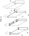
- FIG. 3 is a partial perspective view for explaining the positional relationship among an intermediate holder 9, an end holder 2, a unit cells 8 located at an end of the cell stack, and an end plate 3.
- the intermediate holder 9, the end holder 2, and the end plate 3 will be described with reference to the drawing.
- a plurality of intermediate holders 9 is stacked in the longitudinal direction of the cell stack.
- the material of the intermediate holder 9 is a resin having insulation properties and heat resistance, for example, engineering plastics such as polybutylene terephthalate (PBT) and polycarbonate (PC) or rubber. Since each of the intermediate holders 9 is interposed between the unit cells, the insulation property is secured between adjacent unit cells.
- An intermediate holder 9 has an isolation part 9A and a connection part 9B.
- the isolation part 9A faces a wide surface of a cell and prevents wide surfaces of two adjacent cells from coming into contact with each other.
- the connection part 9B has a ridge part and a valley part and is used for connecting an adjacent intermediate holder and the end holder which will be described later.
- the end holder 2 is arranged between the unit cell 8 arranged at the front end of the cell stack and the end plate 3 and between the unit cell 8 arranged at the rear end and the end plate 3. Since the end holders 2 are each interposed between each pair of the unit cells 8 and the end plates 3, the insulation property between the end plates and the unit cells is secured.
- the end holder 2 has an isolation part 2A, a connection part 2B, and a fixing part 2C.
- the isolation part 2A faces the wide surface of the cell and the end plate and prevents the wide surface of the cell and the end plate from coming into contact with each other.
- the connection part 2B has a ridge part and a valley part and is used for connection with the adjacent intermediate holder.
- the fixing part 2C protrudes from the end holder toward the end plate 3.
- the fixing part 2C is a part for fastening and electrically connecting the end busbar and the external terminal cable and is integrated with an insert nut 10 or an insert bolt.
- the fixing part is structured to be inserted in an accommodating part 3A of the end plate 3, which will be described later, and transfers the rotational torque applied to the fixing part when the end busbar and the external terminal cable are fastened, which ensures stability of the fixing part.
- Adjacent intermediate holders or an intermediate holder and an end holder are connected by fitting connection parts of the respective holders. Specifically, fitting a connection part 9B of an intermediate holder and a connection part 9B of an adjacent intermediate holder results in connection of the adjacent intermediate holders, and fitting a connection part 9B of an intermediate holder and a connection part 2B of an end holder results in connection of the intermediate holder and the end holder.
- the end plate 3 has a rectangular flat plate shape and is formed to have substantially the same size as that of the unit cell 8.
- the end plates are each arranged at the front and the rear in the stacking direction of the cell stack and sandwich the cell stack via the pair of end holders.
- the accommodating part 3A has such a shape as a top surface of the end plate being recessed, with a part of the recess open to the end holder side.
- the shape of the accommodating part 3A is substantially the same as the shape of the fixing part 2C.
- the material of the end plate is a metal such as aluminum or an aluminum alloy.
- the shape of the fixing part of the end holder is not limited.
- a curved surface A may be included as illustrated in FIG. 3 , or a rectangular shape with no curved surface may be employed as illustrated in FIG. 4 .
- the fixing part is a rectangle having no curved surface. This is because, as illustrated in FIG. 5 , when a width Lw of the fixing part is equal to a protruding length Lh of the fixing part, a rectangular shape allows a larger contact area between the fixing part and the end plate.
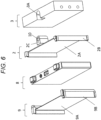
- the position of the fixing part is not limited and may be at a position facing an electrode terminal to be connected with the end busbar as illustrated in FIGS. 3 and 4 or as illustrated in FIG. 6 , may be at a position in the center of two electrode terminals.
- the fixing part is provided at the former position, since the distance between the fixing part and the electrode terminal is short, the end busbar can be shortened to reduce the wiring resistance.
- two types of end holders are necessary. However, in the case of providing fixing parts at the latter position, only one type of shape can be employed for end holders.
- the side frames 4 are arranged symmetrically on the left and right in the stacking direction of the cell stack. As illustrated in FIG. 1 , the side frames 4 are physically connected by the pair of end plates 3 and bolts 11.
- the side frames 4 are manufactured by cutting a metal plate such as a stainless steel plate or a steel plate having a predetermined thickness into pieces having a predetermined width and then bending and working on details.
- the cell stack 1, together with the end holders 2, is sandwiched by the end plates 3 while the end holders 2 are in contact with the cell stack 1 in the front and rear in the stacking direction thereof, and then the side frames 4 are screwed to the end plates 3 by the bolts 11.
- the side frames 4 are screwed to the end plates 3 by the bolts 11
- the cell stack and the end cell holders sandwiched between the pair of end plates are held in a state of being compressed by a predetermined amount.
- the method of fixing the side frames to the end plates using the bolts has been described; however, the side frames may be fixed to the end plates by rivets or by caulking, welding, or other means.
- the fixing parts can be accommodated in the accommodating parts of the end plates, the assembled battery can be downsized. Moreover, since the rotary torque applied to the fixing parts can be received by the accommodating parts of the rigid end plates, the fastening force between an end busbar and an external terminal cable at the fixing part can be increased.
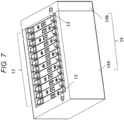
- FIG. 7 is a schematic diagram illustrating an assembled battery according to a second embodiment of the present invention.
- FIG. 8 is an exploded external perspective view of the assembled battery of FIG. 7 .
- the assembled battery according to the present embodiment has the same structure as that of the assembled battery according to the first embodiment except for the side frames and the end plates, and thus description will be given with reference to this figure, and overlapping description on the same structure will be omitted.
- a cell stack 12 is sandwiched between a pair of end holders 13, which are housed in an assembled battery housing 14.
- the assembled battery housing 14 is includes a large part 14A and a small part 14B.
- the assembled battery of the present embodiment is formed by sliding and inserting the cell stack 12 sandwiched by the end holders 13 into the large part 14A of the assembled battery housing 14 from a side thereof, placing the small part 14B to abut against one of the end holders, and then screwing the large part 14A and the small part 14B together by bolts 15.
- FIG. 9 is an external perspective view of the assembled battery housing 14.
- the assembled battery housing 14 has a rectangular box shape having two plate-shaped surfaces (longitudinal surfaces 12C) having large areas, two plate-shaped surfaces (lateral surfaces 12D) having small areas, one plate-shaped bottom 12E, and an opening 12F.
- the material of the assembled battery housing is not limited, but is a metal such as an aluminum alloy or a resin having rigidity such as a glass epoxy resin or a fiber reinforced plastic (FRP) resin.
- the lateral surfaces 14D of the assembled battery housing each have an accommodating part 14G.
- the accommodating part 14G has such a shape as the inner side of the lateral surface 14D being recessed, and the shape can have a curved surface or be a rectangular in accordance with the shape of a fixing part to be accommodated in the accommodating part.
- the position of the accommodating part may be provided at any position in accordance with the position of the fixing part.
- the fixing parts can be accommodated in the accommodating parts of the robust housing, the assembled battery can be downsized with increased the mechanical strength of the assembled battery itself. Moreover, since the rotary torque applied to the fixing parts can be received by the accommodating parts of the rigid assembled battery housing, the fastening force between an end busbar and an external terminal cable at the fixing part can be increased.
- the terminal fixing parts are provided on cell holders at positions facing external terminals of cells. This is to minimize the wiring distance and to reduce the wiring resistance.
- the positions of the terminal fixing parts are not limited to this and may be provided, for example, in the central parts of the cell holders. Such a structure allows the terminal fixing parts to be arranged at the positions where the rigidity is highest in the end plates, thereby enabling provision of the assembled battery which is difficult to break with the increased fastening force between the busbar and the external terminal cable at the fixing part.
- the assembled battery according to the present invention includes: a group of cells in which a plurality of cells, each having electrode terminals, is stacked; plate-shaped members arranged at ends of the group of cells; and cell holders arranged between the plate-shaped members and the group of cells.
- Each of the cell holders is provided with a terminal fixing part of the assembled battery, and each of the plate-shaped members has a fitting part to be fitted to the terminal fixing part.
- the terminal fixing parts have a rectangular shape.
- Such a structure allows the contact area of the terminal fixing parts and the accommodating parts to be increased, and thus the connection between the terminal fixing parts and the accommodating parts can be further strengthened.
- a head of a bolt or a nut is insert-molded in each the terminal fixing parts.
- each of the terminal fixing parts is arranged on a cell holder at a position facing an external terminal.
- Such a structure allows the distance between the external terminal and the terminal fixing part to be minimized.
- each of the terminal fixing parts is arranged at the central portion of a cell holder.
- Such a structure allows the terminal fixing parts to be arranged at the positions where the rigidity is highest in the end plates, thereby enabling provision of the assembled battery which is difficult to break with the increased fastening force between the busbar and the external terminal cable at the fixing part.
Landscapes
- Chemical & Material Sciences (AREA)
- Chemical Kinetics & Catalysis (AREA)
- Electrochemistry (AREA)
- General Chemical & Material Sciences (AREA)
- Inorganic Chemistry (AREA)
- Engineering & Computer Science (AREA)
- Composite Materials (AREA)
- Materials Engineering (AREA)
- Battery Mounting, Suspending (AREA)
- Connection Of Batteries Or Terminals (AREA)
Claims (7)
- Eine Zusammengebaute Batterie umfassend:eine Gruppe von Zellen (8), in der eine Vielzahl von Zellen (8), die jeweils Elektrodenanschlüsse aufweisen, gestapelt ist;plattenförmige Elemente, die an Enden der Gruppe von Zellen (8) angeordnet sind; undZellenhalter (2), die zwischen den plattenförmigen Elementen und der Gruppe von Zellen (8) angeordnet sind,wobei jeder der Zellenhalter (2) mit einem Anschlussbefestigungsteil (2C) der zusammengebauten Batterie versehen ist und jedes der plattenförmigen Elemente ein Passteil (3A, 14G) aufweist, das an das Anschlussbefestigungsteil (2C) zu passen ist, und das Anschlussbefestigungsteil (2C) in dem Anschlusspassteil (3A, 14G) aufgenommen ist.
- Zusammengebaute Batterie nach Anspruch 1,
wobei die plattenförmigen Elemente Endplatten (3) sind. - Zusammengebaute Batterie nach Anspruch 1,
wobei die plattenförmigen Elemente ein Teil eines Gehäuses (14) sind. - Zusammengebaute Batterie nach Anspruch 2 oder 3,
wobei der Anschlussbefestigungsteil (2C) eine rechteckige Form aufweist. - Zusammengebaute Batterie nach einem der Ansprüche 2 bis 4,
wobei ein Kopf eines Bolzens oder einer Mutter (10) in den Anschlussbefestigungsteil (2C) einsatzgeformt ist. - Zusammengebaute Batterie nach einem der Ansprüche 2 bis 5,
wobei der Anschlussbefestigungsteil (2C) an dem Zellenhalter (2) an einer Position angeordnet ist, die einem externen Anschluss einer der Zellen (8) zugewandt ist. - Zusammengebaute Batterie nach einem der Ansprüche 2 bis 5,
wobei der Anschlussbefestigungsteil (2C) an einem mittleren Abschnitt des Zellenhalters (2) angeordnet ist.
Applications Claiming Priority (2)
| Application Number | Priority Date | Filing Date | Title |
|---|---|---|---|
| JP2016194553A JP6752674B2 (ja) | 2016-09-30 | 2016-09-30 | 組電池 |
| PCT/JP2017/028348 WO2018061477A1 (ja) | 2016-09-30 | 2017-08-04 | 組電池 |
Publications (3)
| Publication Number | Publication Date |
|---|---|
| EP3522252A1 EP3522252A1 (de) | 2019-08-07 |
| EP3522252A4 EP3522252A4 (de) | 2020-05-13 |
| EP3522252B1 true EP3522252B1 (de) | 2025-04-23 |
Family
ID=61762715
Family Applications (1)
| Application Number | Title | Priority Date | Filing Date |
|---|---|---|---|
| EP17855435.8A Active EP3522252B1 (de) | 2016-09-30 | 2017-08-04 | Montierte batterie |
Country Status (5)
| Country | Link |
|---|---|
| US (1) | US11264666B2 (de) |
| EP (1) | EP3522252B1 (de) |
| JP (1) | JP6752674B2 (de) |
| CN (1) | CN109792010B (de) |
| WO (1) | WO2018061477A1 (de) |
Families Citing this family (17)
| Publication number | Priority date | Publication date | Assignee | Title |
|---|---|---|---|---|
| US11699832B2 (en) | 2017-09-14 | 2023-07-11 | Vehicle Energy Japan Inc. | Battery module |
| JP6770542B2 (ja) * | 2018-02-22 | 2020-10-14 | 本田技研工業株式会社 | 電源装置 |
| KR102315847B1 (ko) | 2018-10-05 | 2021-10-21 | 주식회사 엘지에너지솔루션 | 용접 불량을 방지할 수 있는 전지팩 프레임을 포함하는 전지팩 및 이를 제조하기 위한 가압 지그 |
| JP7174482B2 (ja) * | 2018-10-16 | 2022-11-17 | ビークルエナジージャパン株式会社 | 電池モジュール |
| JP7056520B2 (ja) * | 2018-11-08 | 2022-04-19 | トヨタ自動車株式会社 | 電池パック |
| CN210403878U (zh) * | 2019-08-15 | 2020-04-24 | 宁德时代新能源科技股份有限公司 | 电池模组 |
| US11791511B2 (en) | 2019-11-19 | 2023-10-17 | Sion Power Corporation | Thermally insulating compressible components for battery packs |
| EP4062484A1 (de) | 2019-11-19 | 2022-09-28 | Sion Power Corporation | Batterien sowie zugehörige systeme und verfahren |
| US11984575B2 (en) | 2019-11-19 | 2024-05-14 | Sion Power Corporation | Battery alignment, and associated systems and methods |
| US11978917B2 (en) | 2019-11-19 | 2024-05-07 | Sion Power Corporation | Batteries with components including carbon fiber, and associated systems and methods |
| CN111064251B (zh) * | 2019-12-27 | 2021-12-28 | 安徽正熹标王新能源有限公司 | 一种电池自动充电系统 |
| KR102874744B1 (ko) * | 2020-03-12 | 2025-10-22 | 주식회사 엘지에너지솔루션 | 에너지 밀도가 향상된 전지 모듈 및 이를 포함하는 전지 팩 |
| JPWO2023145584A1 (de) * | 2022-01-26 | 2023-08-03 | ||
| JP2023136702A (ja) * | 2022-03-17 | 2023-09-29 | 株式会社Gsユアサ | 蓄電装置 |
| JP7597085B2 (ja) * | 2022-07-19 | 2024-12-10 | トヨタ自動車株式会社 | 電池パックケース |
| JP7810828B2 (ja) * | 2022-12-26 | 2026-02-03 | ビークルエナジージャパン株式会社 | 組電池 |
| JPWO2024209796A1 (de) * | 2023-04-06 | 2024-10-10 |
Family Cites Families (24)
| Publication number | Priority date | Publication date | Assignee | Title |
|---|---|---|---|---|
| JP4457812B2 (ja) * | 2004-08-30 | 2010-04-28 | 新神戸電機株式会社 | 組電池及びモジュール電池 |
| KR101103755B1 (ko) * | 2008-09-03 | 2012-01-06 | 에스케이이노베이션 주식회사 | 버스 바 구비 리튬 2차 전지 단위 셋 및 버스 바 구비 리튬2차 전지 셋 |
| JP5288971B2 (ja) | 2008-09-27 | 2013-09-11 | 三洋電機株式会社 | バッテリシステム |
| KR101700254B1 (ko) * | 2009-05-14 | 2017-01-26 | 가부시키가이샤 지에스 유아사 | 집합 전지 |
| JP2011049158A (ja) * | 2009-07-29 | 2011-03-10 | Sanyo Electric Co Ltd | バッテリモジュール、バッテリシステムおよび電動車両 |
| JP2011222490A (ja) * | 2010-03-24 | 2011-11-04 | Denso Corp | 電池パック |
| JP5243507B2 (ja) * | 2010-09-14 | 2013-07-24 | 本田技研工業株式会社 | 電池モジュール |
| JP5394343B2 (ja) * | 2010-09-14 | 2014-01-22 | 本田技研工業株式会社 | 電池モジュール |
| EP2659531B1 (de) * | 2010-12-28 | 2016-10-05 | Yazaki Corporation | Stromversorgungsvorrichtung |
| JP2012256466A (ja) * | 2011-06-08 | 2012-12-27 | Honda Motor Co Ltd | バッテリモジュール |
| JP5956798B2 (ja) | 2012-03-23 | 2016-07-27 | 富士重工業株式会社 | バッテリモジュール |
| JP5668742B2 (ja) * | 2012-10-18 | 2015-02-12 | トヨタ自動車株式会社 | 蓄電モジュールおよび蓄電装置 |
| JP5712188B2 (ja) * | 2012-11-07 | 2015-05-07 | 本田技研工業株式会社 | 蓄電装置 |
| US9774023B2 (en) | 2013-05-21 | 2017-09-26 | Samsung Sdi Co., Ltd. | Battery module |
| JP6026961B2 (ja) * | 2013-06-18 | 2016-11-16 | 豊田合成株式会社 | 電池セル、電池ユニットおよび電池スタック |
| DE102013111146A1 (de) * | 2013-10-09 | 2015-04-09 | Dr. Ing. H.C. F. Porsche Aktiengesellschaft | Batteriemodul für ein Kraftfahrzeug |
| US10003107B2 (en) | 2014-01-17 | 2018-06-19 | Sanyo Electric Co., Ltd. | Power source device |
| JP6264085B2 (ja) * | 2014-02-20 | 2018-01-24 | 株式会社豊田自動織機 | 電池モジュール |
| JP6254904B2 (ja) * | 2014-05-26 | 2017-12-27 | 本田技研工業株式会社 | 蓄電モジュール及びその固定構造 |
| JP6237479B2 (ja) * | 2014-06-05 | 2017-11-29 | 株式会社豊田自動織機 | 電池モジュール及び電池パック |
| JP6106635B2 (ja) * | 2014-07-11 | 2017-04-05 | 本田技研工業株式会社 | 蓄電モジュール |
| DE102014216407A1 (de) * | 2014-08-19 | 2016-02-25 | Robert Bosch Gmbh | Aufnahme für ein Batteriemodul und Batteriemodul aufweisend eine derartige Aufnahme |
| JP6382640B2 (ja) * | 2014-08-27 | 2018-08-29 | 三洋電機株式会社 | バッテリシステム |
| JP6571513B2 (ja) * | 2015-12-22 | 2019-09-04 | 株式会社Gsユアサ | 蓄電装置 |
-
2016
- 2016-09-30 JP JP2016194553A patent/JP6752674B2/ja active Active
-
2017
- 2017-08-04 WO PCT/JP2017/028348 patent/WO2018061477A1/ja not_active Ceased
- 2017-08-04 CN CN201780042939.6A patent/CN109792010B/zh active Active
- 2017-08-04 EP EP17855435.8A patent/EP3522252B1/de active Active
- 2017-08-04 US US16/330,689 patent/US11264666B2/en active Active
Also Published As
| Publication number | Publication date |
|---|---|
| JP6752674B2 (ja) | 2020-09-09 |
| EP3522252A4 (de) | 2020-05-13 |
| CN109792010B (zh) | 2022-03-04 |
| EP3522252A1 (de) | 2019-08-07 |
| WO2018061477A1 (ja) | 2018-04-05 |
| US11264666B2 (en) | 2022-03-01 |
| JP2018056087A (ja) | 2018-04-05 |
| US20210305646A1 (en) | 2021-09-30 |
| CN109792010A (zh) | 2019-05-21 |
Similar Documents
| Publication | Publication Date | Title |
|---|---|---|
| EP3522252B1 (de) | Montierte batterie | |
| JP6496455B2 (ja) | バッテリーモジュール及びこれを含むバッテリーパック | |
| US11699832B2 (en) | Battery module | |
| KR102444124B1 (ko) | 배터리 모듈 및 이를 포함하는 배터리 팩 | |
| EP2562842B1 (de) | Batteriemodul | |
| EP3010072A1 (de) | Batteriepack | |
| EP2490283A2 (de) | Wiederaufladbare Batterie | |
| KR102210461B1 (ko) | 단위전지모듈과 이를 포함하는 전지모듈 및 전지모듈의 제조방법과 이를 포함하는 전지팩 | |
| EP3664185B1 (de) | Elektroausrüstungsanordnung und batteriepack damit | |
| CN113273022A (zh) | 电池模组、电池组及车辆 | |
| US20130252078A1 (en) | Secondary battery | |
| EP2830121B1 (de) | Wiederaufladbare Batterie | |
| US9153809B2 (en) | Secondary battery including retainer for electrode assembly | |
| KR101783917B1 (ko) | 후크 구조가 구비된 컴팩트 이차전지 모듈 | |
| EP3930028B1 (de) | Batteriemodul | |
| CN217114627U (zh) | 电池和用电装置 | |
| JP6876119B2 (ja) | 電池モジュール | |
| US11848455B2 (en) | Battery module | |
| CN110622340B (zh) | 电池组件以及电池组件的制造方法 | |
| KR102569937B1 (ko) | 전극 리드 연결용 커넥터 및 이를 이용한 배터리 모듈 | |
| CN223743793U (zh) | 电池单体、电池装置、储能装置及用电装置 | |
| CN120432821A (zh) | 电池组和用电设备 |
Legal Events
| Date | Code | Title | Description |
|---|---|---|---|
| STAA | Information on the status of an ep patent application or granted ep patent |
Free format text: STATUS: THE INTERNATIONAL PUBLICATION HAS BEEN MADE |
|
| PUAI | Public reference made under article 153(3) epc to a published international application that has entered the european phase |
Free format text: ORIGINAL CODE: 0009012 |
|
| STAA | Information on the status of an ep patent application or granted ep patent |
Free format text: STATUS: REQUEST FOR EXAMINATION WAS MADE |
|
| 17P | Request for examination filed |
Effective date: 20190430 |
|
| AK | Designated contracting states |
Kind code of ref document: A1 Designated state(s): AL AT BE BG CH CY CZ DE DK EE ES FI FR GB GR HR HU IE IS IT LI LT LU LV MC MK MT NL NO PL PT RO RS SE SI SK SM TR |
|
| AX | Request for extension of the european patent |
Extension state: BA ME |
|
| DAV | Request for validation of the european patent (deleted) | ||
| DAX | Request for extension of the european patent (deleted) | ||
| RAP1 | Party data changed (applicant data changed or rights of an application transferred) |
Owner name: VEHICLE ENERGY JAPAN INC. |
|
| A4 | Supplementary search report drawn up and despatched |
Effective date: 20200409 |
|
| RIC1 | Information provided on ipc code assigned before grant |
Ipc: H01M 2/06 20060101ALI20200403BHEP Ipc: H01M 2/20 20060101ALI20200403BHEP Ipc: H01M 2/30 20060101ALI20200403BHEP Ipc: H01M 2/10 20060101AFI20200403BHEP |
|
| STAA | Information on the status of an ep patent application or granted ep patent |
Free format text: STATUS: EXAMINATION IS IN PROGRESS |
|
| 17Q | First examination report despatched |
Effective date: 20211015 |
|
| RAP1 | Party data changed (applicant data changed or rights of an application transferred) |
Owner name: VEHICLE ENERGY JAPAN INC. |
|
| REG | Reference to a national code |
Ipc: H01M0050176000 Ref country code: DE Ref legal event code: R079 Ref document number: 602017089090 Country of ref document: DE Free format text: PREVIOUS MAIN CLASS: H01M0002100000 Ipc: H01M0050176000 |
|
| GRAP | Despatch of communication of intention to grant a patent |
Free format text: ORIGINAL CODE: EPIDOSNIGR1 |
|
| STAA | Information on the status of an ep patent application or granted ep patent |
Free format text: STATUS: GRANT OF PATENT IS INTENDED |
|
| RIC1 | Information provided on ipc code assigned before grant |
Ipc: H01M 50/553 20210101ALI20241105BHEP Ipc: H01M 50/507 20210101ALI20241105BHEP Ipc: H01M 50/209 20210101ALI20241105BHEP Ipc: H01M 50/176 20210101AFI20241105BHEP |
|
| INTG | Intention to grant announced |
Effective date: 20241121 |
|
| GRAS | Grant fee paid |
Free format text: ORIGINAL CODE: EPIDOSNIGR3 |
|
| GRAA | (expected) grant |
Free format text: ORIGINAL CODE: 0009210 |
|
| STAA | Information on the status of an ep patent application or granted ep patent |
Free format text: STATUS: THE PATENT HAS BEEN GRANTED |
|
| AK | Designated contracting states |
Kind code of ref document: B1 Designated state(s): AL AT BE BG CH CY CZ DE DK EE ES FI FR GB GR HR HU IE IS IT LI LT LU LV MC MK MT NL NO PL PT RO RS SE SI SK SM TR |
|
| REG | Reference to a national code |
Ref country code: GB Ref legal event code: FG4D |
|
| REG | Reference to a national code |
Ref country code: CH Ref legal event code: EP |
|
| REG | Reference to a national code |
Ref country code: DE Ref legal event code: R096 Ref document number: 602017089090 Country of ref document: DE |
|
| REG | Reference to a national code |
Ref country code: IE Ref legal event code: FG4D |
|
| REG | Reference to a national code |
Ref country code: NL Ref legal event code: MP Effective date: 20250423 |
|
| PG25 | Lapsed in a contracting state [announced via postgrant information from national office to epo] |
Ref country code: NL Free format text: LAPSE BECAUSE OF FAILURE TO SUBMIT A TRANSLATION OF THE DESCRIPTION OR TO PAY THE FEE WITHIN THE PRESCRIBED TIME-LIMIT Effective date: 20250423 |
|
| REG | Reference to a national code |
Ref country code: AT Ref legal event code: MK05 Ref document number: 1788719 Country of ref document: AT Kind code of ref document: T Effective date: 20250423 |
|
| PG25 | Lapsed in a contracting state [announced via postgrant information from national office to epo] |
Ref country code: PT Free format text: LAPSE BECAUSE OF FAILURE TO SUBMIT A TRANSLATION OF THE DESCRIPTION OR TO PAY THE FEE WITHIN THE PRESCRIBED TIME-LIMIT Effective date: 20250825 Ref country code: FI Free format text: LAPSE BECAUSE OF FAILURE TO SUBMIT A TRANSLATION OF THE DESCRIPTION OR TO PAY THE FEE WITHIN THE PRESCRIBED TIME-LIMIT Effective date: 20250423 Ref country code: ES Free format text: LAPSE BECAUSE OF FAILURE TO SUBMIT A TRANSLATION OF THE DESCRIPTION OR TO PAY THE FEE WITHIN THE PRESCRIBED TIME-LIMIT Effective date: 20250423 |
|
| PGFP | Annual fee paid to national office [announced via postgrant information from national office to epo] |
Ref country code: DE Payment date: 20250901 Year of fee payment: 9 |
|
| REG | Reference to a national code |
Ref country code: LT Ref legal event code: MG9D |
|
| PG25 | Lapsed in a contracting state [announced via postgrant information from national office to epo] |
Ref country code: GR Free format text: LAPSE BECAUSE OF FAILURE TO SUBMIT A TRANSLATION OF THE DESCRIPTION OR TO PAY THE FEE WITHIN THE PRESCRIBED TIME-LIMIT Effective date: 20250724 Ref country code: NO Free format text: LAPSE BECAUSE OF FAILURE TO SUBMIT A TRANSLATION OF THE DESCRIPTION OR TO PAY THE FEE WITHIN THE PRESCRIBED TIME-LIMIT Effective date: 20250723 |
|
| PG25 | Lapsed in a contracting state [announced via postgrant information from national office to epo] |
Ref country code: PL Free format text: LAPSE BECAUSE OF FAILURE TO SUBMIT A TRANSLATION OF THE DESCRIPTION OR TO PAY THE FEE WITHIN THE PRESCRIBED TIME-LIMIT Effective date: 20250423 |
|
| PG25 | Lapsed in a contracting state [announced via postgrant information from national office to epo] |
Ref country code: BG Free format text: LAPSE BECAUSE OF FAILURE TO SUBMIT A TRANSLATION OF THE DESCRIPTION OR TO PAY THE FEE WITHIN THE PRESCRIBED TIME-LIMIT Effective date: 20250423 |
|
| PG25 | Lapsed in a contracting state [announced via postgrant information from national office to epo] |
Ref country code: HR Free format text: LAPSE BECAUSE OF FAILURE TO SUBMIT A TRANSLATION OF THE DESCRIPTION OR TO PAY THE FEE WITHIN THE PRESCRIBED TIME-LIMIT Effective date: 20250423 |
|
| PG25 | Lapsed in a contracting state [announced via postgrant information from national office to epo] |
Ref country code: AT Free format text: LAPSE BECAUSE OF FAILURE TO SUBMIT A TRANSLATION OF THE DESCRIPTION OR TO PAY THE FEE WITHIN THE PRESCRIBED TIME-LIMIT Effective date: 20250423 |
|
| PGFP | Annual fee paid to national office [announced via postgrant information from national office to epo] |
Ref country code: FR Payment date: 20250827 Year of fee payment: 9 |
|
| PG25 | Lapsed in a contracting state [announced via postgrant information from national office to epo] |
Ref country code: RS Free format text: LAPSE BECAUSE OF FAILURE TO SUBMIT A TRANSLATION OF THE DESCRIPTION OR TO PAY THE FEE WITHIN THE PRESCRIBED TIME-LIMIT Effective date: 20250723 |
|
| PG25 | Lapsed in a contracting state [announced via postgrant information from national office to epo] |
Ref country code: IS Free format text: LAPSE BECAUSE OF FAILURE TO SUBMIT A TRANSLATION OF THE DESCRIPTION OR TO PAY THE FEE WITHIN THE PRESCRIBED TIME-LIMIT Effective date: 20250823 |
|
| PG25 | Lapsed in a contracting state [announced via postgrant information from national office to epo] |
Ref country code: LV Free format text: LAPSE BECAUSE OF FAILURE TO SUBMIT A TRANSLATION OF THE DESCRIPTION OR TO PAY THE FEE WITHIN THE PRESCRIBED TIME-LIMIT Effective date: 20250423 |
|
| PG25 | Lapsed in a contracting state [announced via postgrant information from national office to epo] |
Ref country code: SM Free format text: LAPSE BECAUSE OF FAILURE TO SUBMIT A TRANSLATION OF THE DESCRIPTION OR TO PAY THE FEE WITHIN THE PRESCRIBED TIME-LIMIT Effective date: 20250423 Ref country code: DK Free format text: LAPSE BECAUSE OF FAILURE TO SUBMIT A TRANSLATION OF THE DESCRIPTION OR TO PAY THE FEE WITHIN THE PRESCRIBED TIME-LIMIT Effective date: 20250423 |
|
| PG25 | Lapsed in a contracting state [announced via postgrant information from national office to epo] |
Ref country code: CZ Free format text: LAPSE BECAUSE OF FAILURE TO SUBMIT A TRANSLATION OF THE DESCRIPTION OR TO PAY THE FEE WITHIN THE PRESCRIBED TIME-LIMIT Effective date: 20250423 |
|
| PG25 | Lapsed in a contracting state [announced via postgrant information from national office to epo] |
Ref country code: EE Free format text: LAPSE BECAUSE OF FAILURE TO SUBMIT A TRANSLATION OF THE DESCRIPTION OR TO PAY THE FEE WITHIN THE PRESCRIBED TIME-LIMIT Effective date: 20250423 |
|
| REG | Reference to a national code |
Ref country code: DE Ref legal event code: R097 Ref document number: 602017089090 Country of ref document: DE |
|
| PG25 | Lapsed in a contracting state [announced via postgrant information from national office to epo] |
Ref country code: SK Free format text: LAPSE BECAUSE OF FAILURE TO SUBMIT A TRANSLATION OF THE DESCRIPTION OR TO PAY THE FEE WITHIN THE PRESCRIBED TIME-LIMIT Effective date: 20250423 Ref country code: RO Free format text: LAPSE BECAUSE OF FAILURE TO SUBMIT A TRANSLATION OF THE DESCRIPTION OR TO PAY THE FEE WITHIN THE PRESCRIBED TIME-LIMIT Effective date: 20250423 |
|
| PG25 | Lapsed in a contracting state [announced via postgrant information from national office to epo] |
Ref country code: IT Free format text: LAPSE BECAUSE OF FAILURE TO SUBMIT A TRANSLATION OF THE DESCRIPTION OR TO PAY THE FEE WITHIN THE PRESCRIBED TIME-LIMIT Effective date: 20250423 |
|
| PLBE | No opposition filed within time limit |
Free format text: ORIGINAL CODE: 0009261 |
|
| STAA | Information on the status of an ep patent application or granted ep patent |
Free format text: STATUS: NO OPPOSITION FILED WITHIN TIME LIMIT |
|
| REG | Reference to a national code |
Ref country code: CH Ref legal event code: L10 Free format text: ST27 STATUS EVENT CODE: U-0-0-L10-L00 (AS PROVIDED BY THE NATIONAL OFFICE) Effective date: 20260304 |
|
| REG | Reference to a national code |
Ref country code: CH Ref legal event code: H13 Free format text: ST27 STATUS EVENT CODE: U-0-0-H10-H13 (AS PROVIDED BY THE NATIONAL OFFICE) Effective date: 20260324 |
|
| PG25 | Lapsed in a contracting state [announced via postgrant information from national office to epo] |
Ref country code: MC Free format text: LAPSE BECAUSE OF FAILURE TO SUBMIT A TRANSLATION OF THE DESCRIPTION OR TO PAY THE FEE WITHIN THE PRESCRIBED TIME-LIMIT Effective date: 20250423 |
|
| 26N | No opposition filed |
Effective date: 20260126 |
|
| PG25 | Lapsed in a contracting state [announced via postgrant information from national office to epo] |
Ref country code: LU Free format text: LAPSE BECAUSE OF NON-PAYMENT OF DUE FEES Effective date: 20250804 |