EP3514892B1 - Connecteur enfichable - Google Patents
Connecteur enfichable Download PDFInfo
- Publication number
- EP3514892B1 EP3514892B1 EP18208607.4A EP18208607A EP3514892B1 EP 3514892 B1 EP3514892 B1 EP 3514892B1 EP 18208607 A EP18208607 A EP 18208607A EP 3514892 B1 EP3514892 B1 EP 3514892B1
- Authority
- EP
- European Patent Office
- Prior art keywords
- plug
- extension
- electrical contacts
- mating
- casing wall
- Prior art date
- Legal status (The legal status is an assumption and is not a legal conclusion. Google has not performed a legal analysis and makes no representation as to the accuracy of the status listed.)
- Active
Links
- 230000013011 mating Effects 0.000 claims description 32
- 230000000903 blocking effect Effects 0.000 claims description 3
- 238000003780 insertion Methods 0.000 description 78
- 230000037431 insertion Effects 0.000 description 78
- 238000000034 method Methods 0.000 description 11
- 230000005540 biological transmission Effects 0.000 description 6
- 230000003993 interaction Effects 0.000 description 4
- 238000000465 moulding Methods 0.000 description 4
- 238000005299 abrasion Methods 0.000 description 3
- 230000006735 deficit Effects 0.000 description 2
- 230000008034 disappearance Effects 0.000 description 1
- 230000002349 favourable effect Effects 0.000 description 1
- 230000003287 optical effect Effects 0.000 description 1
- 230000000149 penetrating effect Effects 0.000 description 1
- 230000002265 prevention Effects 0.000 description 1
- 230000008054 signal transmission Effects 0.000 description 1
Images


Classifications
-
- H—ELECTRICITY
- H01—ELECTRIC ELEMENTS
- H01R—ELECTRICALLY-CONDUCTIVE CONNECTIONS; STRUCTURAL ASSOCIATIONS OF A PLURALITY OF MUTUALLY-INSULATED ELECTRICAL CONNECTING ELEMENTS; COUPLING DEVICES; CURRENT COLLECTORS
- H01R13/00—Details of coupling devices of the kinds covered by groups H01R12/70 or H01R24/00 - H01R33/00
- H01R13/64—Means for preventing incorrect coupling
- H01R13/642—Means for preventing incorrect coupling by position or shape of contact members
-
- H—ELECTRICITY
- H01—ELECTRIC ELEMENTS
- H01R—ELECTRICALLY-CONDUCTIVE CONNECTIONS; STRUCTURAL ASSOCIATIONS OF A PLURALITY OF MUTUALLY-INSULATED ELECTRICAL CONNECTING ELEMENTS; COUPLING DEVICES; CURRENT COLLECTORS
- H01R13/00—Details of coupling devices of the kinds covered by groups H01R12/70 or H01R24/00 - H01R33/00
- H01R13/64—Means for preventing incorrect coupling
-
- G—PHYSICS
- G02—OPTICS
- G02B—OPTICAL ELEMENTS, SYSTEMS OR APPARATUS
- G02B6/00—Light guides; Structural details of arrangements comprising light guides and other optical elements, e.g. couplings
- G02B6/24—Coupling light guides
- G02B6/36—Mechanical coupling means
- G02B6/38—Mechanical coupling means having fibre to fibre mating means
- G02B6/3807—Dismountable connectors, i.e. comprising plugs
- G02B6/381—Dismountable connectors, i.e. comprising plugs of the ferrule type, e.g. fibre ends embedded in ferrules, connecting a pair of fibres
- G02B6/3825—Dismountable connectors, i.e. comprising plugs of the ferrule type, e.g. fibre ends embedded in ferrules, connecting a pair of fibres with an intermediate part, e.g. adapter, receptacle, linking two plugs
-
- G—PHYSICS
- G02—OPTICS
- G02B—OPTICAL ELEMENTS, SYSTEMS OR APPARATUS
- G02B6/00—Light guides; Structural details of arrangements comprising light guides and other optical elements, e.g. couplings
- G02B6/24—Coupling light guides
- G02B6/36—Mechanical coupling means
- G02B6/38—Mechanical coupling means having fibre to fibre mating means
- G02B6/3807—Dismountable connectors, i.e. comprising plugs
- G02B6/3833—Details of mounting fibres in ferrules; Assembly methods; Manufacture
- G02B6/3847—Details of mounting fibres in ferrules; Assembly methods; Manufacture with means preventing fibre end damage, e.g. recessed fibre surfaces
- G02B6/3849—Details of mounting fibres in ferrules; Assembly methods; Manufacture with means preventing fibre end damage, e.g. recessed fibre surfaces using mechanical protective elements, e.g. caps, hoods, sealing membranes
-
- G—PHYSICS
- G02—OPTICS
- G02B—OPTICAL ELEMENTS, SYSTEMS OR APPARATUS
- G02B6/00—Light guides; Structural details of arrangements comprising light guides and other optical elements, e.g. couplings
- G02B6/24—Coupling light guides
- G02B6/36—Mechanical coupling means
- G02B6/38—Mechanical coupling means having fibre to fibre mating means
- G02B6/3807—Dismountable connectors, i.e. comprising plugs
- G02B6/3833—Details of mounting fibres in ferrules; Assembly methods; Manufacture
- G02B6/3865—Details of mounting fibres in ferrules; Assembly methods; Manufacture fabricated by using moulding techniques
-
- G—PHYSICS
- G02—OPTICS
- G02B—OPTICAL ELEMENTS, SYSTEMS OR APPARATUS
- G02B6/00—Light guides; Structural details of arrangements comprising light guides and other optical elements, e.g. couplings
- G02B6/24—Coupling light guides
- G02B6/36—Mechanical coupling means
- G02B6/38—Mechanical coupling means having fibre to fibre mating means
- G02B6/3807—Dismountable connectors, i.e. comprising plugs
- G02B6/3869—Mounting ferrules to connector body, i.e. plugs
-
- G—PHYSICS
- G02—OPTICS
- G02B—OPTICAL ELEMENTS, SYSTEMS OR APPARATUS
- G02B6/00—Light guides; Structural details of arrangements comprising light guides and other optical elements, e.g. couplings
- G02B6/24—Coupling light guides
- G02B6/36—Mechanical coupling means
- G02B6/38—Mechanical coupling means having fibre to fibre mating means
- G02B6/3807—Dismountable connectors, i.e. comprising plugs
- G02B6/3873—Connectors using guide surfaces for aligning ferrule ends, e.g. tubes, sleeves, V-grooves, rods, pins, balls
- G02B6/3874—Connectors using guide surfaces for aligning ferrule ends, e.g. tubes, sleeves, V-grooves, rods, pins, balls using tubes, sleeves to align ferrules
- G02B6/3878—Connectors using guide surfaces for aligning ferrule ends, e.g. tubes, sleeves, V-grooves, rods, pins, balls using tubes, sleeves to align ferrules comprising a plurality of ferrules, branching and break-out means
- G02B6/3879—Linking of individual connector plugs to an overconnector, e.g. using clamps, clips, common housings comprising several individual connector plugs
-
- H—ELECTRICITY
- H01—ELECTRIC ELEMENTS
- H01R—ELECTRICALLY-CONDUCTIVE CONNECTIONS; STRUCTURAL ASSOCIATIONS OF A PLURALITY OF MUTUALLY-INSULATED ELECTRICAL CONNECTING ELEMENTS; COUPLING DEVICES; CURRENT COLLECTORS
- H01R13/00—Details of coupling devices of the kinds covered by groups H01R12/70 or H01R24/00 - H01R33/00
- H01R13/46—Bases; Cases
- H01R13/502—Bases; Cases composed of different pieces
-
- H—ELECTRICITY
- H01—ELECTRIC ELEMENTS
- H01R—ELECTRICALLY-CONDUCTIVE CONNECTIONS; STRUCTURAL ASSOCIATIONS OF A PLURALITY OF MUTUALLY-INSULATED ELECTRICAL CONNECTING ELEMENTS; COUPLING DEVICES; CURRENT COLLECTORS
- H01R13/00—Details of coupling devices of the kinds covered by groups H01R12/70 or H01R24/00 - H01R33/00
- H01R13/64—Means for preventing incorrect coupling
- H01R13/645—Means for preventing incorrect coupling by exchangeable elements on case or base
-
- G—PHYSICS
- G02—OPTICS
- G02B—OPTICAL ELEMENTS, SYSTEMS OR APPARATUS
- G02B6/00—Light guides; Structural details of arrangements comprising light guides and other optical elements, e.g. couplings
- G02B6/24—Coupling light guides
- G02B6/42—Coupling light guides with opto-electronic elements
- G02B6/4296—Coupling light guides with opto-electronic elements coupling with sources of high radiant energy, e.g. high power lasers, high temperature light sources
- G02B2006/4297—Coupling light guides with opto-electronic elements coupling with sources of high radiant energy, e.g. high power lasers, high temperature light sources having protection means, e.g. protecting humans against accidental exposure to harmful laser radiation
-
- H—ELECTRICITY
- H01—ELECTRIC ELEMENTS
- H01R—ELECTRICALLY-CONDUCTIVE CONNECTIONS; STRUCTURAL ASSOCIATIONS OF A PLURALITY OF MUTUALLY-INSULATED ELECTRICAL CONNECTING ELEMENTS; COUPLING DEVICES; CURRENT COLLECTORS
- H01R13/00—Details of coupling devices of the kinds covered by groups H01R12/70 or H01R24/00 - H01R33/00
- H01R13/62—Means for facilitating engagement or disengagement of coupling parts or for holding them in engagement
- H01R13/625—Casing or ring with bayonet engagement
-
- H—ELECTRICITY
- H01—ELECTRIC ELEMENTS
- H01R—ELECTRICALLY-CONDUCTIVE CONNECTIONS; STRUCTURAL ASSOCIATIONS OF A PLURALITY OF MUTUALLY-INSULATED ELECTRICAL CONNECTING ELEMENTS; COUPLING DEVICES; CURRENT COLLECTORS
- H01R13/00—Details of coupling devices of the kinds covered by groups H01R12/70 or H01R24/00 - H01R33/00
- H01R13/66—Structural association with built-in electrical component
- H01R13/70—Structural association with built-in electrical component with built-in switch
- H01R13/71—Contact members of coupling parts operating as switch, e.g. linear or rotational movement required after mechanical engagement of coupling part to establish electrical connection
Definitions
- the present invention relates to a plug connection according to the preamble of patent claim 1.
- Plug connections for the transmission of electric current are known in the prior art and e.g. in the Community designs 001229827, in particular 001229827-0001 and -0006, 002677641, in particular 002677641-0001, and 001393623-0001 and -0002.
- the projections and the corresponding receiving slots when properly operated in the prior art, prevent connectors that do not belong together from being inserted into one another. Furthermore, it is ensured that associated connectors can only be plugged into each other when used correctly in the specified or intended insertion position.
- a generic connector with additional molded part and counter-molded part is in the EP 2 209 171 A1 shown.
- the invention proposes a connector according to claim 1.
- the male connector in the interior of the extension process additionally has at least one molded part and the female connector in the interior of the extension process receptacle additionally has at least one countermolded part, the molded part and the countermolded part jointly a blocking device for preventing electrical contacting of the electrical contacts with the electrical ones Form counter-contacts when inserting the plug-in extension into the plug-in extension receptacle, starting from a position deviating from the clearly defined insertion position.
- the invention provides that the insertion extension can be inserted into the insertion extension receptacle starting from the predetermined insertion position in the insertion direction to achieve a fully inserted position and can be rotated around the insertion direction from the fully inserted position into an end position, in the end position the electrical contacts are electrically contacted with the electrical counter contacts.
- the insertion direction advantageously coincides with the longitudinal central axes of the insertion extension and the insertion extension receptacle or is coaxial with these.
- the end position mentioned in which the electrical contacts are electrically contacted with the electrical mating contacts, is only reached when a linear insertion process in the insertion direction initially takes place, starting from the clearly specified insertion position. With this linear insertion process, the fully inserted position is reached, from which the insertion extension, preferably the entire male connector, is then rotated around the insertion direction into the end position.
- the receiving slot in which the receiving slot is also arranged, at least one receiving channel running in a circumferential direction and adjoining the receiving slot is arranged, in which the projection during rotation from the fully inserted position into the end position is led.
- the molded part in the interior of the male connector and the counterpart in the interior of the female connector provides an additional security measure that prevents the electrical contacts of the male connector from being accidentally connected to the electrical mating contacts of the female connector in an incorrectly conductive manner, that is, electrically contacted .
- damage or even complete disappearance of the projections and / or receiving slots due to abrasion, wear or other wear and tear so that these can no longer ensure that the male and female plug connectors start exclusively from the clearly defined plug-in position, i.e.
- the molded part and the corresponding counter-molded part still form an additional security measure, which, when the female and male plug connectors are incorrectly plugged into one another, still ensures that it at least does not incorrect electrical contacting of the electrical contacts and the electrical counter-contacts occurs.
- the connectors are inserted incorrectly or intentionally, usually with the appropriate use of force. In this case too, at least one incorrect electrical contact between the electrical contacts and the electrical counter-contacts can be prevented by the interaction of the molded part and the counter-molded part.
- the projections and / or receiving slots on the plug-in extension point outward, on a surface or outer surface of the plug-in extension wall facing away from the interior of the plug-in extension.
- the consequence of this is that they are exposed to increased wear and tear and can therefore be damaged or even removed entirely.
- the arrangement of the molded part in the interior of the insertion process and the counterpart in the interior of the insertion process has the advantage that the molded part and the The countermold is or is particularly well protected from the corresponding plug-in extension wall or the corresponding plug-in extension wall against external influences and in particular against abrasion or other impairments, which further contributes to the safe prevention of electrical contacting of the electrical contacts with the wrong electrical counter-contacts.
- the electrical contact could also be referred to as an electrically conductive connection of the electrical contacts to the electrical counter-contacts.
- plug connections according to the invention can be both an electrical signal transmission, in which rather low electrical powers are transmitted, and an electrical transmission of power with correspondingly high currents and / or voltages.
- Plug connections according to the invention can thus be used both for electrical data transmission and for electrical power transmission, e.g. be designed for the power supply of electrical devices.
- plug connections for the transmission of electrical energy and / or electrical signals are also possible.
- plug connections according to the invention do not necessarily have to be limited to transmitting only electrical currents and / or voltages.
- plug connections according to the invention e.g. optical data transmission or the like can also be integrated.
- Both the male connector and the female connector of the plug connection according to the invention can be cable connectors, that is to say connectors which are connected directly to the cable, but also so-called chassis connectors, that is to say connectors which are attached to device housings.
- the female connector could also be called a socket.
- the projections could also be referred to as elevations, and the receiving slots could also be referred to as depressions or depressions or grooves.
- the projections can be arranged both on the plug-in extension wall and on the plug-in receiving wall and protrude beyond them. They can point inwards, i.e. towards the respective interior, but also outwards.
- the receiving slots can also be provided both on the plug-in extension wall and on the plug-in receiving wall or in the respective wall. Mixed forms are also conceivable. It can be one, but also several projections and / or receiving slots per jacket wall. In the following, the protrusion and the receiving slot are usually spoken of in singular numbers. But this is only a linguistic simplification.
- it can be one or more projections or one or more receiving slots.
- the projections and the corresponding receiving slots serve to ensure that the male connector in the undamaged state of the projections and receiving slots can only be inserted into the insertion extension receptacle in the insertion direction, starting from the unambiguous insertion position specified by the projection and the insertion slot. Put simply, the protrusions and slots in the undamaged condition and with proper handling actually ensure that the male connector is not inserted incorrectly into the female connector.
- the molded part according to the invention in cooperation with the corresponding counter-molded part at least prevents the male connector from being inserted into the female connector to such an extent that the electrical connector Contacts and the electrical counter contacts are connected incorrectly.
- the unambiguous insertion position predefined by the projection and the receiving slot is also referred to here briefly as the unambiguous predefined insertion position or only as the predefined insertion position.
- the shape and position of the receiving slot corresponding to a respective projection corresponds to the shape and position or location of the corresponding projection so that in the undamaged state of the projection and receiving slot and when used correctly, insertion is only possible starting from the clearly specified insertion position .
- electrical counter-contacts is only used to clarify that these are the electrical contact elements of the female connector. Neither the concept of the electrical contacts of the male connector nor that of the electrical mating contacts of the female connector says anything about the number and physical configuration of the respective electrical contact elements. This can be designed very differently and correspondingly to one another. Both the number of electrical contacts of the male connector and the number of electrical mating contacts of the female connector can vary. It can be one, two, three or more electrical contacts and accordingly also one, two, three or more electrical counter-contacts. Three electrical contacts and correspondingly three electrical mating contacts are particularly preferred. As a rule, in the case of plug connections according to the invention, the number of electrical contacts of the male plug connector corresponds to the number of electrical mating contacts of the female plug connector.
- the molded part has at least one stop surface and the counter-molded part has at least one counter-stop surface, the stop surface and the counter-stop surface when the plug is inserted to form the locking device Push the extension in the insertion direction into the insertion receptacle starting from a position deviating from the clearly specified insertion position and to prevent the electrical contacting of the electrical contacts with the electrical mating contacts from completely inserting the insertion extension in the insertion direction into the insertion extension.
- molded part and counter-molded part as well as the stop surface and counter-stop surface is, like the electrical contacts and the electrical counter-contacts, ultimately also a convention that only serves to simplify and simplify the linguistic assignment to the male or female connector unify. These terms therefore say nothing about the specific design and arrangement in the respective connector.
- the molded part is arranged centrally in the interior of the extension, preferably on a longitudinal central axis of the extension.
- the molded part is preferably located between the electrical contacts in the interior of the insertion extension.
- the counter-molded part is also advantageously arranged centrally in the interior of the insertion extension, preferably on a longitudinal central axis of the insertion extension.
- the counter-shaped part is preferably also located between the electrical counter-contacts.
- a part which is the molded part or the counter-molded part, has at least one free space into which the other of these parts penetrates into the plug-in extension receptacle starting from the predetermined plug-in position when the plug-in extension is inserted in the plug-in direction.
- the free space can thus be formed both on the molded part and on the counter-molded part.
- the other part in each case, that is to say the corresponding counterpart or the molded part, can then correspondingly penetrate into this free space when the insertion extension is inserted, starting from the clearly defined insertion position.
- the free space can be V-shaped. It can also be several, for example two opposing free spaces.
- the part penetrating into the free space or the free spaces that is to say correspondingly the molded part or the counter-molded part, is rotatably mounted in the free space, particularly preferably rotatably mounted between two rotary stops.
- the, preferably all, electrical contacts are arranged on a common circular path of the electrical contacts and / or that the, preferably all, electrical counter contacts are arranged on a common circular path of the electrical counter contacts. It is preferably also provided that an outer surface of the insert wall wall and / or an inner surface of the extension wall wall apart from projections or receiving slots arranged there and / or receiving channels arranged there is or are at least partially circular cylinder jacket-shaped.
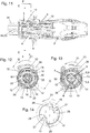
- the male connector 2 of the connector 1 according to the invention shown here by way of example is a cable connector in this example and in Fig. 1 in a perspective and in Fig. 2 shown in a side view.
- Fig. 3 shows a view in the direction of the plug-in extension 4 of this male connector 2.
- the corresponding female connector 3 is designed as a so-called chassis socket or as a so-called chassis connector, which is intended to be attached to the housing of an electrical device.
- a female connector 3 according to the invention like the male connector 2 shown here, could also be designed as a cable connector, without this having to change anything in the components essential to the invention. this applies the other way round also for the male connector 2. This could also basically be designed as a chassis connector.
- the female connector 3 shown here can be screwed or otherwise fastened to the housing of the electrical device by means of the fastening holes 36 in the flange 33 in a manner known per se.
- Fig. 4 shows a perspective view of this female connector 3
- Fig. 5 a side view.
- Fig. 6 shows a look into the insertion extension interior 11 of this female connector 3 or its insertion extension 8.
- the male connector 2 has a housing 29, through which the plug-in extension 4 projects.
- the cable grommet 31 On the opposite side of the plug-in extension 4 is the cable grommet 31, through which an electrical cable can be inserted into the male connector 2 in a manner known per se and can be contacted there at the electrical contacts 6 of the plug-in extension 4 or male connector 2 .
- the housing 29, the cable grommet 31 and the slider 30 are ultimately not relevant to the invention and, like the interior of the housing 29 and the cable grommet 31, can be designed as is known per se in the prior art.
- the plug-in extension 4 has a plug-in extension jacket wall 5 which, in the exemplary embodiment shown, is designed in the shape of a circular cylinder jacket, apart from the projections 12 arranged thereon and facing outward, that is to say in particular has an outer surface 25 in the form of a cylindrical cylinder jacket.
- a total of 4 projections 12 are arranged on the outer surface 25, projecting outwards. These four projections 12 differ in their shape and also in their position. As already stated at the beginning, there may also be more or less and differently shaped and also differently arranged projections 12.
- Corresponding receiving slots 13 could equally well be located in the plug-in extension wall 5, if the corresponding projections 12 were formed in the plug-in extension jacket wall 9 of the plug-in extension 4 of the female connector 3. Mixed forms are also conceivable, in which both projections 12 and receiving slots 13 are arranged both on the plug-in extension wall 5 and on the plug-in extension wall 9.
- the plug-in extension jacket wall 5 in any case surrounds the plug-in extension interior 7, in which the electrical contacts 6 are located.
- the plug-in extension jacket wall 5, as in the exemplary embodiment shown here, is advantageously made so long that the electrical contacts 6 are arranged completely recessed in the plug-in extension interior 7 and do not project beyond it.
- the recessed electrical contacts 6 are clearly visible in the insertion extension interior 7. It can also be seen that in this exemplary embodiment they are arranged on a common circular path 23.
- the molded part 15 with its outward-facing stop surfaces 17 is arranged centrally in the insertion interior 7. The shape and function of this molded part 15 and in particular its interaction with the counter-molded part 16 of the female connector 3 is explained in more detail below.
- the centrally arranged molded part 15 lies here on the longitudinal central axis 19 of the insertion extension 4 and between the electrical contacts 6.
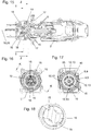
- the insertion extension jacket wall 9 of the insertion extension 8 surrounds the insertion extension interior 11 in which the electrical mating contacts 10 are arranged.
- these electrical mating contacts 10 are also all arranged on a common circular path 24 and are arranged sunk in the insertion extension receptacle interior 11.
- the external contacts 34 which are in conductive connection with the electrical mating contacts 10, are used to connect cables or the like and are at the rear, ie on the side facing away from the flange 33, beyond the housing 32 of the female connector 3.
- Central to the insert extension receptacle interior 11 is also the counter-shaped part 16 according to the invention with its two Counter stop surfaces 18, the two free spaces 27 and the rotary stops 28 are arranged.
- the longitudinal central axis 20 of the insertion extension receptacle 8 also runs through the counter-molding 16.
- the insertion extension receptacle jacket wall 9 has a circular-cylindrical inner surface 26, which in this exemplary embodiment is broken through by the receiving slots 13.
- Each receiving slot 13 is adjoined by a receiving channel 22, which is likewise arranged in the plug-in extension receiving jacket wall 9 and breaks through the inner surface 26.
- the male connector 2 with its insertion extension 4 is inserted into the insertion extension receptacle 8 in the insertion direction 14, starting from the clear insertion position in the insertion direction 14 predetermined by the projections 12 and the corresponding receiving slots 13.
- the fully inserted position can be reached, in which the electrical contacts 6 in this exemplary embodiment are not yet electrically conductively connected or contacted to the electrical counter-contacts 10.
- the plug-in extension 4 In order to reach the end position, in which this is the case, the plug-in extension 4 must first be rotated in the circumferential direction 21 starting from the fully inserted position; only then does the electrical contacts 6 make electrical contact with the electrical contacts in this exemplary embodiment Mating contacts 10.
- a seal 35 known per se is located in the plug-in extension space 8 of the female connector 3.
- the front end of the plug-in extension jacket wall 5 is pressed against this seal 35 in the fully inserted position.
- the plug-in extension 4 or the entire male connector 2 To reach the end position according to the 11 to 14 and thus for the electrical contacting of the electrical contacts 6 with the electrical mating contacts 10, the plug-in extension 4 or the entire male connector 2, starting from the fully inserted position according to FIG 7 to 10 rotated in the circumferential direction 21.
- the projections 12 of the insertion extension are guided in the receiving channels 22 of the insertion extension receiving jacket wall 9.
- the electrical contacts 6 are then electrically connected to the electrical mating contacts 10, as is particularly good in the 11 and 13 you can see.
Landscapes
- Physics & Mathematics (AREA)
- General Physics & Mathematics (AREA)
- Optics & Photonics (AREA)
- Details Of Connecting Devices For Male And Female Coupling (AREA)
- Connector Housings Or Holding Contact Members (AREA)
Claims (8)
- Raccord enfichable (1) pour la transmission d'un courant électrique, comprenant un connecteur mâle (2) et un connecteur femelle (3), le connecteur mâle (2) étant muni d'un tenon d'enfichage (4) avec une paroi d'enveloppe du tenon d'enfichage (5) et des contacts électriques (6), les contacts électriques (6) étant disposés dans un espace intérieur du tenon d'enfichage (7) entouré par la paroi d'enveloppe du tenon d'enfichage (5), et le connecteur femelle (3) étant muni d'un logement du tenon d'enfichage (8) avec une paroi d'enveloppe du logement du tenon d'enfichage (9) et de contre-contacts électriques (10), les contre-contacts électriques (10) étant disposés dans un espace intérieur du logement du tenon d'enfichage (11) entouré par la paroi d'enveloppe du logement du tenon d'enfichage (9), au moins une saillie (12) étant disposée sur une paroi d'enveloppe, qui est la paroi d'enveloppe du tenon d'enfichage (5) ou la paroi d'enveloppe du logement du tenon d'enfichage (9), et l'autre de ces parois d'enveloppe étant munie d'au moins une fente de réception (13) correspondant à la saillie (12), le tenon d'enfichage (4), dans un état intact de la saillie (12) et de la fente de réception (13), ne pouvant être inséré dans le logement du tenon d'enfichage (8) dans une direction d'enfichage (14) qu'en partant d'une position d'enfichage non ambiguë prédéterminée par la saillie (12) et la fente de réception (13), et le connecteur mâle (2) étant muni en outre d'au moins une partie profilée (15) dans l'espace intérieur du tenon d'enfichage (7) et le connecteur femelle (3) étant muni en outre d'au moins une contrepartie profilée (16) dans l'espace intérieur du logement du tenon d'enfichage (11), la partie profilée (15) et la contrepartie profilée (16) formant ensemble un dispositif de blocage pour empêcher un contact électrique des contacts électriques (6) avec les contre-contacts électriques (10) durant un enfichage du tenon d'enfichage (4) dans le logement du tenon d'enfichage (8) en partant d'une position différente de la position prédéterminée sans ambigüité, caractérisé en ce que, en partant de la position d'enfichage sans ambigüité prédéterminée, le tenon d'enfichage (4) peut être enfiché dans le logement du tenon d'enfichage (8) dans la direction enfichable (14) pour atteindre une position complètement enfichée, et, en partant de la position complètement enfichée, il peut être tournée autour de la direction enfichable (14) dans une position finale, les contacts électriques (6), dans la position finale, étant en contact électrique avec les contre-contacts électriques (10), au moins un canal de réception (22), situé à la suite de la fente de réception (13) et s'étendant en direction circonférentielle (21), étant disposé dans la paroi d'enveloppe dans laquelle est également disposée la fente de réception (13), canal dans lequel la saillie (12) est guidée lors de la rotation depuis la position complètement enfichée dans la position finale.
- Raccord enfichable (1) selon la revendication 1, caractérisé en ce que la partie profilée (15) est munie d'au moins une surface de butée (17) et la contrepartie profilée (16) est munie d'au moins une contre-surface de butée (18), la surface de butée (17) et la contre-surface de butée (18), pour former le dispositif de blocage, venant en butée l'une contre l'autre lors de l'enfichage du tenon d'enfichage (4) dans le logement du tenon d'enfichage (8) dans la direction d'enfichage en partant d'une position qui diffère de la position d'enfichage sans ambigüité prédéterminée, et la surface de butée (17) et la contre-surface de butée (18), afin d'empêcher les contacts électriques (6) d'établir un contact électrique avec les contre-contacts électriques (10), empêchant que le tenon d'enfichage (4) ne soit entièrement enfiché dans le logement du tenon d'enfichage (8) dans la direction d'enfichage (14).
- Raccord enfichable (1) selon la revendication 1 ou 2, caractérisé en ce que la partie profilée (15) est disposée au centre dans l'espace intérieur du tenon d'enfichage (7), de préférence sur un axe central longitudinal (19) du tenon d'enfichage (4), et/ou entre les contacts électriques (6).
- Raccord enfichable (1) selon l'une des revendications 1 à 3, caractérisé en ce que la contrepartie profilée (16) est disposée de façon centrée dans l'espace intérieur du logement de tenon d'enfichage (11), de préférence sur un axe central longitudinal (20) du logement du tenon d'enfichage (8), et/ou entre les contre-contacts électriques (10).
- Raccord enfichable (1) selon l'une des revendications 1 à 4, caractérisé en ce qu'une pluralité de saillies (12), de préférence quatre, de formes différentes les unes des autres et/ou disposées en des positions différentes les unes des autres sont disposées sur une paroi d'enveloppe qui est la paroi d'enveloppe du tenon d'enfichage (5) ou la paroi d'enveloppe du logement du tenon d'enfichage (9), et l'autre de ces parois d'enveloppe est munie d'un nombre de fentes de réception (13) correspondant aux saillies (12), lesquelles fentes de réception sont de formes différentes les unes des autres et/ou disposées en des positions différentes les unes des autres.
- Raccord enfichable (1) selon l'une des revendications 1 à 5, caractérisé en ce que les contacts électriques (6), de préférence tous, sont disposés sur un tracé circulaire commun (23) des contacts électriques (6) et/ou en ce que les contre-contacts électriques (10), de préférence tous, sont disposés sur un tracé circulaire commun (24) des contre-contacts électriques (10).
- Raccord enfichable (1) selon l'une des revendications 1 à 6, caractérisé en ce qu'une surface extérieure (25) de la paroi d'enveloppe du tenon d'enfichage (5) et/ou une surface intérieure (26) de la paroi d'enveloppe du logement du tenon d'enfichage (9) est ou sont formée(s) au moins par endroit sous la forme d'une enveloppe cylindrique circulaire, à l'exception des saillies (12) ou fentes de réception (13) disposées dessus et/ou des canaux de réception (22) disposés dessus.
- Raccord enfichable (1) selon l'une des revendications 1 à 7, caractérisé en ce qu'une partie, qui est la partie profilée (15) ou la contrepartie profilée (16), est munie d'au moins un espace libre (27), de préférence en forme de V considéré en vue de dessus, espace libre dans lequel pénètre l'autre de ces parties lors de l'enfichage du tenon d'enfichage (4) dans le logement du tenon d'enfichage (8) dans la direction d'enfichage (14) en partant de la position d'enfichage sans ambigüité prédéfinie, la pièce pénétrant dans l'espace libre (27) pouvant de préférence tourner dans l'espace libre (27) entre deux butées de rotation (28).
Priority Applications (2)
| Application Number | Priority Date | Filing Date | Title |
|---|---|---|---|
| EP19216920.9A EP3641070A1 (fr) | 2018-01-23 | 2018-11-27 | Connecteur enfichable |
| EP20202736.3A EP3787128A1 (fr) | 2018-01-23 | 2018-11-27 | Raccordement enfichable |
Applications Claiming Priority (1)
| Application Number | Priority Date | Filing Date | Title |
|---|---|---|---|
| DE102018101431.7A DE102018101431A1 (de) | 2018-01-23 | 2018-01-23 | Steckverbindung |
Related Child Applications (3)
| Application Number | Title | Priority Date | Filing Date |
|---|---|---|---|
| EP19216920.9A Division EP3641070A1 (fr) | 2018-01-23 | 2018-11-27 | Connecteur enfichable |
| EP19216920.9A Division-Into EP3641070A1 (fr) | 2018-01-23 | 2018-11-27 | Connecteur enfichable |
| EP20202736.3A Division EP3787128A1 (fr) | 2018-01-23 | 2018-11-27 | Raccordement enfichable |
Publications (2)
| Publication Number | Publication Date |
|---|---|
| EP3514892A1 EP3514892A1 (fr) | 2019-07-24 |
| EP3514892B1 true EP3514892B1 (fr) | 2020-05-20 |
Family
ID=64500270
Family Applications (3)
| Application Number | Title | Priority Date | Filing Date |
|---|---|---|---|
| EP19216920.9A Withdrawn EP3641070A1 (fr) | 2018-01-23 | 2018-11-27 | Connecteur enfichable |
| EP18208607.4A Active EP3514892B1 (fr) | 2018-01-23 | 2018-11-27 | Connecteur enfichable |
| EP20202736.3A Pending EP3787128A1 (fr) | 2018-01-23 | 2018-11-27 | Raccordement enfichable |
Family Applications Before (1)
| Application Number | Title | Priority Date | Filing Date |
|---|---|---|---|
| EP19216920.9A Withdrawn EP3641070A1 (fr) | 2018-01-23 | 2018-11-27 | Connecteur enfichable |
Family Applications After (1)
| Application Number | Title | Priority Date | Filing Date |
|---|---|---|---|
| EP20202736.3A Pending EP3787128A1 (fr) | 2018-01-23 | 2018-11-27 | Raccordement enfichable |
Country Status (5)
| Country | Link |
|---|---|
| US (2) | US10823914B2 (fr) |
| EP (3) | EP3641070A1 (fr) |
| JP (2) | JP6705027B2 (fr) |
| CN (2) | CN112886338B (fr) |
| DE (1) | DE102018101431A1 (fr) |
Cited By (1)
| Publication number | Priority date | Publication date | Assignee | Title |
|---|---|---|---|---|
| WO2023232256A1 (fr) | 2022-06-02 | 2023-12-07 | Neutrik Ag | Connecteur intégré |
Families Citing this family (3)
| Publication number | Priority date | Publication date | Assignee | Title |
|---|---|---|---|---|
| US10615530B2 (en) | 2017-06-06 | 2020-04-07 | Amphenol Corporation | Spring loaded electrical connector |
| DE102018101431A1 (de) * | 2018-01-23 | 2019-07-25 | Neutrik Ag | Steckverbindung |
| CN113097790B (zh) * | 2021-04-08 | 2022-10-21 | 山东聚辰电缆有限公司 | 一种电力电缆接头及电力电缆接头的连接工艺 |
Citations (1)
| Publication number | Priority date | Publication date | Assignee | Title |
|---|---|---|---|---|
| WO2019138196A1 (fr) * | 2018-01-12 | 2019-07-18 | Societe D'exploitation Des Procedes Marechal | Socle de prise equipe d'un disque et d'un obturateur |
Family Cites Families (42)
| Publication number | Priority date | Publication date | Assignee | Title |
|---|---|---|---|---|
| US2986612A (en) * | 1959-04-06 | 1961-05-30 | Hubbell Inc Harvey | Electrical connectors for industrial uses |
| US3351887A (en) * | 1965-06-28 | 1967-11-07 | Eldon D Jones | Interlocking electrical connection |
| US3339039A (en) * | 1965-09-10 | 1967-08-29 | Arrow Hart & Hegeman Electric | Electrical connector with contactprotecting and arc-quenching shield |
| AT313404B (de) * | 1970-03-31 | 1974-02-25 | Staff & Schwarz Gmbh | Elektrische Kupplung zum Verbinden elektrischer Leitungen |
| JPH0229176U (fr) * | 1988-08-18 | 1990-02-26 | ||
| JP2779104B2 (ja) | 1992-11-12 | 1998-07-23 | 日本原子力研究所 | 簡易着脱電気コネクター |
| DE19851301C2 (de) * | 1998-11-06 | 2001-05-17 | Framatome Connectors Int | Elektrischer Steckverbinder für Zünder |
| JP2000208209A (ja) | 1999-01-14 | 2000-07-28 | D D K Ltd | 電源接続用コネクタ |
| US6394661B1 (en) * | 1999-02-09 | 2002-05-28 | Fiber Systems International | Fiber optic connector having receptacle housing for radially aligning mating inserts |
| US6234683B1 (en) * | 1999-09-13 | 2001-05-22 | Stratos Lightwave, Inc. | Field repairable hermaphroditic connector |
| US6394856B1 (en) * | 2000-01-04 | 2002-05-28 | Tyco Electronics Corp. | Electrical connector with programmable keying |
| US6986686B2 (en) * | 2001-02-23 | 2006-01-17 | Olympus Corporation | Electrical plug for supplying electric power from a power supply to a medical instrument |
| US6764351B2 (en) * | 2001-08-27 | 2004-07-20 | Campagnie Deutsch GmbH | Electrical connector |
| US7429170B2 (en) * | 2005-10-31 | 2008-09-30 | Owens-Illinois Closure Inc. | Method and machine for compression molding closure shells |
| DE102006001630A1 (de) * | 2006-01-11 | 2007-07-12 | Neutrik Aktiengesellschaft | Steckerbuchse |
| JP4557915B2 (ja) | 2006-03-24 | 2010-10-06 | 株式会社七星科学研究所 | シャッター付き電気コネクタ |
| JP4777148B2 (ja) | 2006-05-31 | 2011-09-21 | 矢崎総業株式会社 | コネクタ |
| EP2130270A1 (fr) * | 2007-03-27 | 2009-12-09 | Van-System s.r.l | Prise électrique |
| US7585116B2 (en) * | 2007-04-12 | 2009-09-08 | Fiber Systems International | Fiber optic connector having hermaphroditic coupling mechanism |
| US7435112B1 (en) * | 2008-02-08 | 2008-10-14 | Tyco Electronics Corporation | Electrical connector having a mechanical mating cycle limitation |
| JP5341532B2 (ja) * | 2009-01-19 | 2013-11-13 | 第一電子工業株式会社 | 1対の誤嵌合防止キー及び該キーを用いた電気コネクタ |
| JP4847564B2 (ja) * | 2009-07-22 | 2011-12-28 | 日本航空電子工業株式会社 | コネクタ組立体 |
| JP4925372B2 (ja) * | 2009-12-28 | 2012-04-25 | 日本航空電子工業株式会社 | 光コネクタアダプタ |
| US8550843B2 (en) * | 2010-11-22 | 2013-10-08 | Andrew Llc | Tabbed connector interface |
| JP5775335B2 (ja) | 2011-03-16 | 2015-09-09 | 矢崎総業株式会社 | 突き当てコネクタ |
| DE102011113062A1 (de) * | 2011-09-09 | 2013-03-14 | Amphenol-Tuchel Electronics Gmbh | Kontaktgeschützter Steckverbinder |
| CN102870023B (zh) * | 2012-06-26 | 2014-07-30 | 华为技术有限公司 | 光纤连接头、光纤适配器及光纤连接器 |
| JP5946377B2 (ja) * | 2012-09-07 | 2016-07-06 | 矢崎総業株式会社 | コネクタ |
| US9252539B2 (en) * | 2012-11-02 | 2016-02-02 | Hubbell Incorporated | Internally switched female receptacle or connector with plug-latching safety interlock |
| DE202013006297U1 (de) | 2013-07-11 | 2013-07-25 | Rosenberger Hochfrequenztechnik Gmbh & Co. Kg | Steckverbinder |
| EP3234672B1 (fr) * | 2014-12-19 | 2021-09-08 | CommScope Telecommunications (Shanghai) Co. Ltd. | Connecteur de fibres optiques de l'état solide à ressort pré-comprimé |
| US9755382B2 (en) * | 2015-03-13 | 2017-09-05 | Senko Advanced Components, Inc. | Connector system with interchangeable connector modules for optical fibers, electrical conductors, or both |
| USD779434S1 (en) * | 2015-04-09 | 2017-02-21 | Neutrik Ag | Electrical connector |
| DE202015003177U1 (de) | 2015-04-30 | 2015-05-13 | Rosenberger Hochfrequenztechnik Gmbh & Co. Kg | Steckverbindung und Satz von Steckverbindungen |
| EP3391115A4 (fr) * | 2015-12-16 | 2019-07-17 | Commscope Technologies LLC | Connecteur à fibre optique installé sur le terrain |
| US10128594B2 (en) * | 2015-12-22 | 2018-11-13 | Biosense Webster (Israel) Ltd. | Connectors having three-dimensional surfaces |
| US9905956B2 (en) * | 2015-12-22 | 2018-02-27 | Biosense Webster (Israel) Ltd. | Preventing unwanted contact between terminals |
| DE102016101255A1 (de) * | 2016-01-25 | 2017-07-27 | Neutrik Ag | Verbinder |
| JP2018081144A (ja) * | 2016-11-14 | 2018-05-24 | 住友電気工業株式会社 | 光コネクタ |
| JP2019000797A (ja) * | 2017-06-14 | 2019-01-10 | 大日本印刷株式会社 | ウェブクリーナーおよびウェブクリーナーシステム |
| DE102018101431A1 (de) * | 2018-01-23 | 2019-07-25 | Neutrik Ag | Steckverbindung |
| GB2594946A (en) * | 2020-05-12 | 2021-11-17 | Gyrus Medical Ltd | RF Shaver connector |
-
2018
- 2018-01-23 DE DE102018101431.7A patent/DE102018101431A1/de active Pending
- 2018-11-27 EP EP19216920.9A patent/EP3641070A1/fr not_active Withdrawn
- 2018-11-27 EP EP18208607.4A patent/EP3514892B1/fr active Active
- 2018-11-27 EP EP20202736.3A patent/EP3787128A1/fr active Pending
-
2019
- 2019-01-07 JP JP2019000797A patent/JP6705027B2/ja active Active
- 2019-01-11 US US16/245,751 patent/US10823914B2/en active Active
- 2019-01-23 CN CN202110187223.3A patent/CN112886338B/zh active Active
- 2019-01-23 CN CN201910063569.5A patent/CN110071397B/zh active Active
-
2020
- 2020-05-12 JP JP2020084081A patent/JP7333286B2/ja active Active
- 2020-10-13 US US17/068,968 patent/US11409050B2/en active Active
Patent Citations (1)
| Publication number | Priority date | Publication date | Assignee | Title |
|---|---|---|---|---|
| WO2019138196A1 (fr) * | 2018-01-12 | 2019-07-18 | Societe D'exploitation Des Procedes Marechal | Socle de prise equipe d'un disque et d'un obturateur |
Cited By (1)
| Publication number | Priority date | Publication date | Assignee | Title |
|---|---|---|---|---|
| WO2023232256A1 (fr) | 2022-06-02 | 2023-12-07 | Neutrik Ag | Connecteur intégré |
Also Published As
| Publication number | Publication date |
|---|---|
| EP3514892A1 (fr) | 2019-07-24 |
| EP3787128A1 (fr) | 2021-03-03 |
| CN110071397A (zh) | 2019-07-30 |
| EP3641070A1 (fr) | 2020-04-22 |
| US20190227239A1 (en) | 2019-07-25 |
| US10823914B2 (en) | 2020-11-03 |
| JP2019129148A (ja) | 2019-08-01 |
| JP2020181818A (ja) | 2020-11-05 |
| CN112886338B (zh) | 2023-05-09 |
| CN110071397B (zh) | 2021-02-05 |
| JP7333286B2 (ja) | 2023-08-24 |
| JP6705027B2 (ja) | 2020-06-03 |
| US20210026079A1 (en) | 2021-01-28 |
| US11409050B2 (en) | 2022-08-09 |
| DE102018101431A1 (de) | 2019-07-25 |
| CN112886338A (zh) | 2021-06-01 |
Similar Documents
| Publication | Publication Date | Title |
|---|---|---|
| EP3514892B1 (fr) | Connecteur enfichable | |
| DE102006016882B4 (de) | Steckverbinder | |
| EP1730815B1 (fr) | Fiche de raccordement coaxiale pour cartes a circuits imprimes, munie d'une compensation de tolerance par ressort | |
| DE69838831T2 (de) | Elektrischer Verbinder mit Kontaktlagessicherungsvorrichtung | |
| EP2517313B1 (fr) | Système de connexion par connecteur pour connexion électrique enfichable protégée contre l'humidité | |
| EP3057183B1 (fr) | Connecteur étanche | |
| DE102006004238B4 (de) | Steckverbinder | |
| EP0856918A2 (fr) | Douille de connection coaxiale | |
| EP3122589B1 (fr) | Dispositif embrochable réalisé sous forme de prolongateur ou de fiche | |
| EP3176885B1 (fr) | Systeme de connecteur a fiches | |
| DE3408323A1 (de) | Elektrischer verbinder | |
| EP3516741B1 (fr) | Connecteur doté d'une protection | |
| DE102015015202B4 (de) | Steckverbinder und Stecksystem | |
| EP3961821B1 (fr) | Dispositif de connexion doté d'un connecteur enfichable et d'un connecteur enfichable complémentaire | |
| EP3386033B1 (fr) | Corps isolant d'une unité de connecteur | |
| EP3937313B1 (fr) | Connecteur à fiches électrique | |
| DE102015201089A1 (de) | Zwischengehäuse mit einer CPA-Aufnahme und Steckverbindersysteme umfassend ein solches | |
| EP1959523A1 (fr) | Dispositif de codage pour connecteur à fiches | |
| DE102018122848A1 (de) | Modulelement zur Aufnahme in einem Halterahmen für einen Steckverbinder | |
| DE102015217409A1 (de) | lsolationskörper für ein steckbares Verbindungselement | |
| EP3096410B1 (fr) | Connecteur a fiches comprenant un verrou destine au verrouillage secondaire de partenaires de contact | |
| EP3713018B1 (fr) | Connecteur enfichable électrique | |
| EP3306755B1 (fr) | Direct connecteur muni de pions de codage amovibles | |
| EP1134850B1 (fr) | Adaptateur et connecteur pour un adaptateur | |
| DE102020109823A1 (de) | Entladestecker für einen Akku eines Elektrofahrrades |
Legal Events
| Date | Code | Title | Description |
|---|---|---|---|
| PUAI | Public reference made under article 153(3) epc to a published international application that has entered the european phase |
Free format text: ORIGINAL CODE: 0009012 |
|
| STAA | Information on the status of an ep patent application or granted ep patent |
Free format text: STATUS: THE APPLICATION HAS BEEN PUBLISHED |
|
| AK | Designated contracting states |
Kind code of ref document: A1 Designated state(s): AL AT BE BG CH CY CZ DE DK EE ES FI FR GB GR HR HU IE IS IT LI LT LU LV MC MK MT NL NO PL PT RO RS SE SI SK SM TR |
|
| AX | Request for extension of the european patent |
Extension state: BA ME |
|
| STAA | Information on the status of an ep patent application or granted ep patent |
Free format text: STATUS: REQUEST FOR EXAMINATION WAS MADE |
|
| 17P | Request for examination filed |
Effective date: 20190927 |
|
| RBV | Designated contracting states (corrected) |
Designated state(s): AL AT BE BG CH CY CZ DE DK EE ES FI FR GB GR HR HU IE IS IT LI LT LU LV MC MK MT NL NO PL PT RO RS SE SI SK SM TR |
|
| GRAP | Despatch of communication of intention to grant a patent |
Free format text: ORIGINAL CODE: EPIDOSNIGR1 |
|
| STAA | Information on the status of an ep patent application or granted ep patent |
Free format text: STATUS: GRANT OF PATENT IS INTENDED |
|
| GRAS | Grant fee paid |
Free format text: ORIGINAL CODE: EPIDOSNIGR3 |
|
| RIC1 | Information provided on ipc code assigned before grant |
Ipc: H01R 13/64 20060101AFI20191112BHEP Ipc: H01R 13/71 20060101ALN20191112BHEP Ipc: H01R 13/625 20060101ALN20191112BHEP |
|
| INTG | Intention to grant announced |
Effective date: 20191127 |
|
| GRAJ | Information related to disapproval of communication of intention to grant by the applicant or resumption of examination proceedings by the epo deleted |
Free format text: ORIGINAL CODE: EPIDOSDIGR1 |
|
| GRAL | Information related to payment of fee for publishing/printing deleted |
Free format text: ORIGINAL CODE: EPIDOSDIGR3 |
|
| STAA | Information on the status of an ep patent application or granted ep patent |
Free format text: STATUS: REQUEST FOR EXAMINATION WAS MADE |
|
| GRAR | Information related to intention to grant a patent recorded |
Free format text: ORIGINAL CODE: EPIDOSNIGR71 |
|
| STAA | Information on the status of an ep patent application or granted ep patent |
Free format text: STATUS: GRANT OF PATENT IS INTENDED |
|
| INTC | Intention to grant announced (deleted) | ||
| RIC1 | Information provided on ipc code assigned before grant |
Ipc: H01R 13/71 20060101ALN20200108BHEP Ipc: H01R 13/625 20060101ALN20200108BHEP Ipc: H01R 13/64 20060101AFI20200108BHEP |
|
| RIN1 | Information on inventor provided before grant (corrected) |
Inventor name: DOBLER, OLIVER |
|
| INTG | Intention to grant announced |
Effective date: 20200124 |
|
| GRAA | (expected) grant |
Free format text: ORIGINAL CODE: 0009210 |
|
| STAA | Information on the status of an ep patent application or granted ep patent |
Free format text: STATUS: THE PATENT HAS BEEN GRANTED |
|
| AK | Designated contracting states |
Kind code of ref document: B1 Designated state(s): AL AT BE BG CH CY CZ DE DK EE ES FI FR GB GR HR HU IE IS IT LI LT LU LV MC MK MT NL NO PL PT RO RS SE SI SK SM TR |
|
| REG | Reference to a national code |
Ref country code: GB Ref legal event code: FG4D Free format text: NOT ENGLISH |
|
| REG | Reference to a national code |
Ref country code: CH Ref legal event code: EP |
|
| REG | Reference to a national code |
Ref country code: DE Ref legal event code: R096 Ref document number: 502018001485 Country of ref document: DE |
|
| REG | Reference to a national code |
Ref country code: AT Ref legal event code: REF Ref document number: 1273235 Country of ref document: AT Kind code of ref document: T Effective date: 20200615 |
|
| REG | Reference to a national code |
Ref country code: CH Ref legal event code: NV Representative=s name: ALDO ROEMPLER PATENTANWALT, CH |
|
| REG | Reference to a national code |
Ref country code: LT Ref legal event code: MG4D |
|
| REG | Reference to a national code |
Ref country code: NL Ref legal event code: MP Effective date: 20200520 |
|
| PG25 | Lapsed in a contracting state [announced via postgrant information from national office to epo] |
Ref country code: IS Free format text: LAPSE BECAUSE OF FAILURE TO SUBMIT A TRANSLATION OF THE DESCRIPTION OR TO PAY THE FEE WITHIN THE PRESCRIBED TIME-LIMIT Effective date: 20200920 Ref country code: PT Free format text: LAPSE BECAUSE OF FAILURE TO SUBMIT A TRANSLATION OF THE DESCRIPTION OR TO PAY THE FEE WITHIN THE PRESCRIBED TIME-LIMIT Effective date: 20200921 Ref country code: FI Free format text: LAPSE BECAUSE OF FAILURE TO SUBMIT A TRANSLATION OF THE DESCRIPTION OR TO PAY THE FEE WITHIN THE PRESCRIBED TIME-LIMIT Effective date: 20200520 Ref country code: SE Free format text: LAPSE BECAUSE OF FAILURE TO SUBMIT A TRANSLATION OF THE DESCRIPTION OR TO PAY THE FEE WITHIN THE PRESCRIBED TIME-LIMIT Effective date: 20200520 Ref country code: LT Free format text: LAPSE BECAUSE OF FAILURE TO SUBMIT A TRANSLATION OF THE DESCRIPTION OR TO PAY THE FEE WITHIN THE PRESCRIBED TIME-LIMIT Effective date: 20200520 Ref country code: NO Free format text: LAPSE BECAUSE OF FAILURE TO SUBMIT A TRANSLATION OF THE DESCRIPTION OR TO PAY THE FEE WITHIN THE PRESCRIBED TIME-LIMIT Effective date: 20200820 Ref country code: GR Free format text: LAPSE BECAUSE OF FAILURE TO SUBMIT A TRANSLATION OF THE DESCRIPTION OR TO PAY THE FEE WITHIN THE PRESCRIBED TIME-LIMIT Effective date: 20200821 |
|
| PG25 | Lapsed in a contracting state [announced via postgrant information from national office to epo] |
Ref country code: BG Free format text: LAPSE BECAUSE OF FAILURE TO SUBMIT A TRANSLATION OF THE DESCRIPTION OR TO PAY THE FEE WITHIN THE PRESCRIBED TIME-LIMIT Effective date: 20200820 Ref country code: RS Free format text: LAPSE BECAUSE OF FAILURE TO SUBMIT A TRANSLATION OF THE DESCRIPTION OR TO PAY THE FEE WITHIN THE PRESCRIBED TIME-LIMIT Effective date: 20200520 Ref country code: LV Free format text: LAPSE BECAUSE OF FAILURE TO SUBMIT A TRANSLATION OF THE DESCRIPTION OR TO PAY THE FEE WITHIN THE PRESCRIBED TIME-LIMIT Effective date: 20200520 Ref country code: HR Free format text: LAPSE BECAUSE OF FAILURE TO SUBMIT A TRANSLATION OF THE DESCRIPTION OR TO PAY THE FEE WITHIN THE PRESCRIBED TIME-LIMIT Effective date: 20200520 |
|
| PG25 | Lapsed in a contracting state [announced via postgrant information from national office to epo] |
Ref country code: NL Free format text: LAPSE BECAUSE OF FAILURE TO SUBMIT A TRANSLATION OF THE DESCRIPTION OR TO PAY THE FEE WITHIN THE PRESCRIBED TIME-LIMIT Effective date: 20200520 Ref country code: AL Free format text: LAPSE BECAUSE OF FAILURE TO SUBMIT A TRANSLATION OF THE DESCRIPTION OR TO PAY THE FEE WITHIN THE PRESCRIBED TIME-LIMIT Effective date: 20200520 |
|
| PG25 | Lapsed in a contracting state [announced via postgrant information from national office to epo] |
Ref country code: DK Free format text: LAPSE BECAUSE OF FAILURE TO SUBMIT A TRANSLATION OF THE DESCRIPTION OR TO PAY THE FEE WITHIN THE PRESCRIBED TIME-LIMIT Effective date: 20200520 Ref country code: ES Free format text: LAPSE BECAUSE OF FAILURE TO SUBMIT A TRANSLATION OF THE DESCRIPTION OR TO PAY THE FEE WITHIN THE PRESCRIBED TIME-LIMIT Effective date: 20200520 Ref country code: SM Free format text: LAPSE BECAUSE OF FAILURE TO SUBMIT A TRANSLATION OF THE DESCRIPTION OR TO PAY THE FEE WITHIN THE PRESCRIBED TIME-LIMIT Effective date: 20200520 Ref country code: EE Free format text: LAPSE BECAUSE OF FAILURE TO SUBMIT A TRANSLATION OF THE DESCRIPTION OR TO PAY THE FEE WITHIN THE PRESCRIBED TIME-LIMIT Effective date: 20200520 Ref country code: CZ Free format text: LAPSE BECAUSE OF FAILURE TO SUBMIT A TRANSLATION OF THE DESCRIPTION OR TO PAY THE FEE WITHIN THE PRESCRIBED TIME-LIMIT Effective date: 20200520 Ref country code: RO Free format text: LAPSE BECAUSE OF FAILURE TO SUBMIT A TRANSLATION OF THE DESCRIPTION OR TO PAY THE FEE WITHIN THE PRESCRIBED TIME-LIMIT Effective date: 20200520 Ref country code: IT Free format text: LAPSE BECAUSE OF FAILURE TO SUBMIT A TRANSLATION OF THE DESCRIPTION OR TO PAY THE FEE WITHIN THE PRESCRIBED TIME-LIMIT Effective date: 20200520 |
|
| REG | Reference to a national code |
Ref country code: DE Ref legal event code: R097 Ref document number: 502018001485 Country of ref document: DE |
|
| PG25 | Lapsed in a contracting state [announced via postgrant information from national office to epo] |
Ref country code: PL Free format text: LAPSE BECAUSE OF FAILURE TO SUBMIT A TRANSLATION OF THE DESCRIPTION OR TO PAY THE FEE WITHIN THE PRESCRIBED TIME-LIMIT Effective date: 20200520 Ref country code: SK Free format text: LAPSE BECAUSE OF FAILURE TO SUBMIT A TRANSLATION OF THE DESCRIPTION OR TO PAY THE FEE WITHIN THE PRESCRIBED TIME-LIMIT Effective date: 20200520 |
|
| REG | Reference to a national code |
Ref country code: CH Ref legal event code: NV Representative=s name: ABP PATENT NETWORK AG, CH |
|
| REG | Reference to a national code |
Ref country code: DE Ref legal event code: R082 Ref document number: 502018001485 Country of ref document: DE Representative=s name: KAMINSKI HARMANN PATENTANWAELTE AG, LI Ref country code: DE Ref legal event code: R082 Ref document number: 502018001485 Country of ref document: DE Representative=s name: ABP BURGER RECHTSANWALTSGESELLSCHAFT MBH, DE |
|
| PLBE | No opposition filed within time limit |
Free format text: ORIGINAL CODE: 0009261 |
|
| STAA | Information on the status of an ep patent application or granted ep patent |
Free format text: STATUS: NO OPPOSITION FILED WITHIN TIME LIMIT |
|
| 26N | No opposition filed |
Effective date: 20210223 |
|
| PG25 | Lapsed in a contracting state [announced via postgrant information from national office to epo] |
Ref country code: SI Free format text: LAPSE BECAUSE OF FAILURE TO SUBMIT A TRANSLATION OF THE DESCRIPTION OR TO PAY THE FEE WITHIN THE PRESCRIBED TIME-LIMIT Effective date: 20200520 |
|
| PG25 | Lapsed in a contracting state [announced via postgrant information from national office to epo] |
Ref country code: MC Free format text: LAPSE BECAUSE OF FAILURE TO SUBMIT A TRANSLATION OF THE DESCRIPTION OR TO PAY THE FEE WITHIN THE PRESCRIBED TIME-LIMIT Effective date: 20200520 |
|
| PG25 | Lapsed in a contracting state [announced via postgrant information from national office to epo] |
Ref country code: LU Free format text: LAPSE BECAUSE OF NON-PAYMENT OF DUE FEES Effective date: 20201127 |
|
| REG | Reference to a national code |
Ref country code: BE Ref legal event code: MM Effective date: 20201130 |
|
| PG25 | Lapsed in a contracting state [announced via postgrant information from national office to epo] |
Ref country code: IE Free format text: LAPSE BECAUSE OF NON-PAYMENT OF DUE FEES Effective date: 20201127 |
|
| PG25 | Lapsed in a contracting state [announced via postgrant information from national office to epo] |
Ref country code: MT Free format text: LAPSE BECAUSE OF FAILURE TO SUBMIT A TRANSLATION OF THE DESCRIPTION OR TO PAY THE FEE WITHIN THE PRESCRIBED TIME-LIMIT Effective date: 20200520 Ref country code: CY Free format text: LAPSE BECAUSE OF FAILURE TO SUBMIT A TRANSLATION OF THE DESCRIPTION OR TO PAY THE FEE WITHIN THE PRESCRIBED TIME-LIMIT Effective date: 20200520 |
|
| PG25 | Lapsed in a contracting state [announced via postgrant information from national office to epo] |
Ref country code: MK Free format text: LAPSE BECAUSE OF FAILURE TO SUBMIT A TRANSLATION OF THE DESCRIPTION OR TO PAY THE FEE WITHIN THE PRESCRIBED TIME-LIMIT Effective date: 20200520 |
|
| PG25 | Lapsed in a contracting state [announced via postgrant information from national office to epo] |
Ref country code: BE Free format text: LAPSE BECAUSE OF NON-PAYMENT OF DUE FEES Effective date: 20201130 |
|
| REG | Reference to a national code |
Ref country code: DE Ref legal event code: R082 Ref document number: 502018001485 Country of ref document: DE Representative=s name: KAMINSKI HARMANN PATENTANWAELTE AG, LI Ref country code: DE Ref legal event code: R082 Country of ref document: DE |
|
| REG | Reference to a national code |
Ref country code: DE Ref legal event code: R082 Ref document number: 502018001485 Country of ref document: DE Representative=s name: KAMINSKI HARMANN PATENTANWAELTE AG, LI |
|
| PGFP | Annual fee paid to national office [announced via postgrant information from national office to epo] |
Ref country code: GB Payment date: 20231123 Year of fee payment: 6 |
|
| PGFP | Annual fee paid to national office [announced via postgrant information from national office to epo] |
Ref country code: TR Payment date: 20231124 Year of fee payment: 6 Ref country code: FR Payment date: 20231120 Year of fee payment: 6 Ref country code: DE Payment date: 20231121 Year of fee payment: 6 Ref country code: CH Payment date: 20231202 Year of fee payment: 6 Ref country code: AT Payment date: 20231121 Year of fee payment: 6 |