EP3176885B1 - Systeme de connecteur a fiches - Google Patents
Systeme de connecteur a fiches Download PDFInfo
- Publication number
- EP3176885B1 EP3176885B1 EP16187168.6A EP16187168A EP3176885B1 EP 3176885 B1 EP3176885 B1 EP 3176885B1 EP 16187168 A EP16187168 A EP 16187168A EP 3176885 B1 EP3176885 B1 EP 3176885B1
- Authority
- EP
- European Patent Office
- Prior art keywords
- plug connector
- connector
- plug
- connection
- bayonet
- Prior art date
- Legal status (The legal status is an assumption and is not a legal conclusion. Google has not performed a legal analysis and makes no representation as to the accuracy of the status listed.)
- Active
Links
- 230000037431 insertion Effects 0.000 claims description 26
- 238000003780 insertion Methods 0.000 claims description 26
- 230000000295 complement effect Effects 0.000 claims description 19
- 239000000463 material Substances 0.000 claims description 8
- 230000002441 reversible effect Effects 0.000 claims description 3
- 239000013013 elastic material Substances 0.000 claims 1
- 230000013011 mating Effects 0.000 description 5
- 230000005489 elastic deformation Effects 0.000 description 3
- 208000012886 Vertigo Diseases 0.000 description 2
- 239000000243 solution Substances 0.000 description 2
- 230000000712 assembly Effects 0.000 description 1
- 238000000429 assembly Methods 0.000 description 1
- 230000001419 dependent effect Effects 0.000 description 1
- 239000000834 fixative Substances 0.000 description 1
- 238000001746 injection moulding Methods 0.000 description 1
- 238000004519 manufacturing process Methods 0.000 description 1
Images

Classifications
-
- H—ELECTRICITY
- H01—ELECTRIC ELEMENTS
- H01R—ELECTRICALLY-CONDUCTIVE CONNECTIONS; STRUCTURAL ASSOCIATIONS OF A PLURALITY OF MUTUALLY-INSULATED ELECTRICAL CONNECTING ELEMENTS; COUPLING DEVICES; CURRENT COLLECTORS
- H01R13/00—Details of coupling devices of the kinds covered by groups H01R12/70 or H01R24/00 - H01R33/00
- H01R13/62—Means for facilitating engagement or disengagement of coupling parts or for holding them in engagement
- H01R13/629—Additional means for facilitating engagement or disengagement of coupling parts, e.g. aligning or guiding means, levers, gas pressure electrical locking indicators, manufacturing tolerances
- H01R13/631—Additional means for facilitating engagement or disengagement of coupling parts, e.g. aligning or guiding means, levers, gas pressure electrical locking indicators, manufacturing tolerances for engagement only
-
- H—ELECTRICITY
- H01—ELECTRIC ELEMENTS
- H01R—ELECTRICALLY-CONDUCTIVE CONNECTIONS; STRUCTURAL ASSOCIATIONS OF A PLURALITY OF MUTUALLY-INSULATED ELECTRICAL CONNECTING ELEMENTS; COUPLING DEVICES; CURRENT COLLECTORS
- H01R13/00—Details of coupling devices of the kinds covered by groups H01R12/70 or H01R24/00 - H01R33/00
- H01R13/62—Means for facilitating engagement or disengagement of coupling parts or for holding them in engagement
- H01R13/639—Additional means for holding or locking coupling parts together, after engagement, e.g. separate keylock, retainer strap
-
- H—ELECTRICITY
- H01—ELECTRIC ELEMENTS
- H01R—ELECTRICALLY-CONDUCTIVE CONNECTIONS; STRUCTURAL ASSOCIATIONS OF A PLURALITY OF MUTUALLY-INSULATED ELECTRICAL CONNECTING ELEMENTS; COUPLING DEVICES; CURRENT COLLECTORS
- H01R24/00—Two-part coupling devices, or either of their cooperating parts, characterised by their overall structure
- H01R24/38—Two-part coupling devices, or either of their cooperating parts, characterised by their overall structure having concentrically or coaxially arranged contacts
- H01R24/40—Two-part coupling devices, or either of their cooperating parts, characterised by their overall structure having concentrically or coaxially arranged contacts specially adapted for high frequency
-
- H—ELECTRICITY
- H01—ELECTRIC ELEMENTS
- H01R—ELECTRICALLY-CONDUCTIVE CONNECTIONS; STRUCTURAL ASSOCIATIONS OF A PLURALITY OF MUTUALLY-INSULATED ELECTRICAL CONNECTING ELEMENTS; COUPLING DEVICES; CURRENT COLLECTORS
- H01R13/00—Details of coupling devices of the kinds covered by groups H01R12/70 or H01R24/00 - H01R33/00
- H01R13/02—Contact members
- H01R13/20—Pins, blades, or sockets shaped, or provided with separate member, to retain co-operating parts together
- H01R13/213—Pins, blades, or sockets shaped, or provided with separate member, to retain co-operating parts together by bayonet connection
-
- H—ELECTRICITY
- H01—ELECTRIC ELEMENTS
- H01R—ELECTRICALLY-CONDUCTIVE CONNECTIONS; STRUCTURAL ASSOCIATIONS OF A PLURALITY OF MUTUALLY-INSULATED ELECTRICAL CONNECTING ELEMENTS; COUPLING DEVICES; CURRENT COLLECTORS
- H01R13/00—Details of coupling devices of the kinds covered by groups H01R12/70 or H01R24/00 - H01R33/00
- H01R13/62—Means for facilitating engagement or disengagement of coupling parts or for holding them in engagement
- H01R13/625—Casing or ring with bayonet engagement
-
- H—ELECTRICITY
- H01—ELECTRIC ELEMENTS
- H01R—ELECTRICALLY-CONDUCTIVE CONNECTIONS; STRUCTURAL ASSOCIATIONS OF A PLURALITY OF MUTUALLY-INSULATED ELECTRICAL CONNECTING ELEMENTS; COUPLING DEVICES; CURRENT COLLECTORS
- H01R24/00—Two-part coupling devices, or either of their cooperating parts, characterised by their overall structure
- H01R24/005—Two-part coupling devices, or either of their cooperating parts, characterised by their overall structure requiring successive relative motions to complete the coupling, e.g. bayonet type
-
- H—ELECTRICITY
- H01—ELECTRIC ELEMENTS
- H01R—ELECTRICALLY-CONDUCTIVE CONNECTIONS; STRUCTURAL ASSOCIATIONS OF A PLURALITY OF MUTUALLY-INSULATED ELECTRICAL CONNECTING ELEMENTS; COUPLING DEVICES; CURRENT COLLECTORS
- H01R24/00—Two-part coupling devices, or either of their cooperating parts, characterised by their overall structure
- H01R24/38—Two-part coupling devices, or either of their cooperating parts, characterised by their overall structure having concentrically or coaxially arranged contacts
-
- H—ELECTRICITY
- H01—ELECTRIC ELEMENTS
- H01R—ELECTRICALLY-CONDUCTIVE CONNECTIONS; STRUCTURAL ASSOCIATIONS OF A PLURALITY OF MUTUALLY-INSULATED ELECTRICAL CONNECTING ELEMENTS; COUPLING DEVICES; CURRENT COLLECTORS
- H01R13/00—Details of coupling devices of the kinds covered by groups H01R12/70 or H01R24/00 - H01R33/00
- H01R13/62—Means for facilitating engagement or disengagement of coupling parts or for holding them in engagement
- H01R13/627—Snap or like fastening
- H01R13/6271—Latching means integral with the housing
-
- H—ELECTRICITY
- H01—ELECTRIC ELEMENTS
- H01R—ELECTRICALLY-CONDUCTIVE CONNECTIONS; STRUCTURAL ASSOCIATIONS OF A PLURALITY OF MUTUALLY-INSULATED ELECTRICAL CONNECTING ELEMENTS; COUPLING DEVICES; CURRENT COLLECTORS
- H01R2103/00—Two poles
-
- H—ELECTRICITY
- H01—ELECTRIC ELEMENTS
- H01R—ELECTRICALLY-CONDUCTIVE CONNECTIONS; STRUCTURAL ASSOCIATIONS OF A PLURALITY OF MUTUALLY-INSULATED ELECTRICAL CONNECTING ELEMENTS; COUPLING DEVICES; CURRENT COLLECTORS
- H01R2201/00—Connectors or connections adapted for particular applications
- H01R2201/26—Connectors or connections adapted for particular applications for vehicles
Definitions
- the invention relates to a male connector assembly.
- connection is required for a wide range of applications, e.g. as connections for coaxial cables in high-frequency applications or as connections for other components to one another and to cables, e.g. in the automotive sector.
- the problem with the connection is that loosening of the two plug connections must be avoided. Therefore, a large number of fixing means are known which are intended to prevent the two connectors from becoming detached from one another.
- a fixed connection can therefore be made using a wide variety of fixing means, e.g. using several additional auxiliary elements that create a connection by means of a rotary movement.
- This type of connection is preferably selected for at least approximately cylindrical connectors.
- the connection is achieved via sliding elements which snap into one another via spring elements.
- KR 101 132 375 B1 discloses a connector arrangement according to the preamble of claim 1.
- various additional parts such as pins, snap connections, spring elements, etc. are proposed as a safeguard against unscrewing the connector.
- U.S. 3,805,379 B are locking balls, which are applied in the direction of openings of a locking ring, proposed as a safeguard against unscrewing the connector.
- a connection between a connector and a housing is in the DE 382375 A1 proposed, which deals with the attachment of lamps to a base.
- the U.S. 2006/0172580 A1 proposes a fixation of the plug connection via several means to be connected to one another. In this case, the connection is made mainly by first unscrewing the elements and fixing them by means of spring arms that engage or snap into the corresponding counterparts.
- the DE 91 05436 U1 discloses a connector assembly with an actuating element designed as a rotary ring for fixing the two connectors.
- an actuating element designed as a rotary ring for fixing the two connectors.
- the rotary ring is turned over both connectors by means of a bayonet-type connection so that it accommodates part of the connector.
- the final fixation of the two connectors takes place via locking projections arranged on the outer circumference of one of the connectors and locking recesses arranged inside the rotary ring, which lock together in the end position when the rotary ring is turned open.
- a plug connector arrangement according to claim 1 is proposed with a first plug connector, which is designed to be connected at a first end to a first electrical component and to be connected at a second end to a second plug connector that is complementary to the first plug connector, the first Connector comprises at least a first part of a bayonet-like connection and at least a first locking element of a locking device, which is arranged such that it extends in a plug-in direction.
- the arrangement of the latching element in the insertion direction makes it possible to connect a complementary second connector to the first connector in such a way that both connectors can be dimensioned to a minimum, and as a result several connector arrangements can be arranged very close to one another.
- a bayonet-type connection is understood to be a connection in which one of the two connectors has at least one insertion bevel with a first guide means and the other of the two connectors has a second guide means that fits into the insertion bevel via the first guide means.
- the two connectors are brought together or separated, depending on the direction of movement.
- no overtravel is required or used with a bayonet-type connection.
- Overtravel refers to the guide means snapping into a bulge in the insertion bevel, as a result of which the guide means cannot simply be moved out of the end region of the insertion bevel without the application of force.
- the disadvantage of an overtravel is that in order to release the connection, the plug connectors have to move axially towards one another, so that the electrical contact is passed over several times, which is not advantageous.
- the first part of the bayonet-like connection is formed as an insertion bevel arranged between the first end and the second end and running obliquely to a plug-in direction of the connector, and the first latching element is arranged on the end face of the second end of the first connector is.
- the arrangement of the first latching element on the connector specifies which second connector can be connected to the first connector. Due to the correspondingly arranged first latching element, a miniaturization of both the plug connector and the plug connector arrangement produced from two complementary plug connectors connected to one another is achieved.
- a corresponding arrangement of the first part and the locking element to each other and to the second end of the connector ensures that when There is no overtravel when two connectors are brought together or separated.
- the first latching element is a latching recess or a latching lug.
- the first connector comprises at least two first parts of a bayonet-type connection. In a further embodiment it is provided that the first connector comprises at least two first latching elements. In a further embodiment, the at least two first latching elements are arranged symmetrically to one another.
- the connector arrangement also has a second connector, which is complementary to the first connector and can be plugged into it, and which is set up to be connected to a second electrical component with a first end area and to the first connector with a second end area to be connected.
- the second connector comprises at least a second part of a bayonet-type connection that is complementary to the first connector, and at least one second latching element of a latching device, which is arranged in such a way that it extends in a plugging direction, the at least one second latching element having a shape that matches that of the first Has locking element complementary shape.
- the second part of the bayonet-like connection is arranged at the second end of the second connector as a second guide means and the second latching element is arranged at a distance from the second part of the bayonet-like connection in the direction of the first end of the second connector.
- the second connector is designed to complement the first connector and thus has the same advantages, above all that miniaturization of the overall system made up of the first and second connectors can be achieved.
- first and/or the second plug connector is/are formed in one piece, in two pieces or in several pieces.
- a one-piece connector is very inexpensive, while a two-piece connector has the advantage that assembly on the corresponding component, e.g., a cable, can be simplified. There is also the possibility of constructing the connector in several pieces, if necessary. Which connector is chosen depends on the application.
- the first part of the bayonet-like connection and the second part of the bayonet-like connection are formed and arranged so as to complement one another in such a way that the first connector can be brought together with or separated from the second connector.
- the first latching element and the second latching element are formed and arranged so as to complement one another in such a way that the first latching element latches with the second latching element in a position in which the two connectors are in an end position of the bayonet-like connection.
- the connector arrangement made up of the first and second connectors results in a miniaturization of the connector arrangement, so that a plurality of connector arrangements can be arranged close to one another and are easy to assemble.
- the connector arrangement combines all the advantages of the individual connectors.
- the first part of the bayonet-type connection is designed as a guide lug and the first locking element is designed as a locking lug, elastic deformation of the guide lug and/or the locking lug and/or the material of the plug connector when they are brought together or takes place when the connector is pulled apart in or against the plug-in direction, with the deformation being reversible.
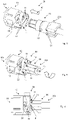
- Figures 1 and 2 12 show views of two complementary first and second connectors 10 and 20 according to an embodiment of a connector assembly of the present invention.
- figure 3 shows the in figure 2 connector 20 shown as a two-piece connector.
- the inside figure 3 Connector shown differs from the one in figure 2 connector shown only in that it is designed in two parts for better pluggability on eg cable and can be connected via connecting elements 23 to form a complete connector.
- the connecting elements 23 can be designed in different ways, as a snap connection, as a screw connection, they can be glued, welded or connected to one another in any other way, as long as the connector is firmly seated on the component.
- a first connector 10 is thus shown, which can be connected at a first end region 101 to an electrical component, for example a cable, a socket or another component.
- an electrical component for example a cable, a socket or another component.
- the first connector 10 can be connected to a second end region 202 of a second, in figure 2 shown, connector 20 are connected, which has a complementary to the first connector 10 shape.
- the body of the first connector 10 has insertion aids 12 and 13 for bringing the two connectors 10 and 20 together.
- the insertion aids 12 and 13 shown comprise insertion bevels 13 arranged opposite one another on the body of the first connector 10, which enable the bayonet-like closure, and a first guide means 12, which is arranged on the end face or end face of the first connector 10 as a recess in the circumference to Record guide lug 22 of a second connector 20 and lead into the insertion slope 13.
- the insertion aid 12 and 13 serves as the first part of a bayonet-like connection in conjunction with the complementary second part of the bayonet-like connection, which is shown in figure 2 correspondingly shown as guide lugs 22 .
- the second connector 20 shown can be connected at a first end region 201 to an electrical component, for example a cable will. At its second end area 202 it is formed in such a way that it can be connected to the first plug connector 10 .
- it is formed as a complementary connector to the first connector 10 in such a way that it has a second guide means 22 as the second part of the bayonet-like connection, which is designed as a guide lug 22 .
- the first and second connectors 10 and 20 are substantially cylindrical. However, any other suitable form can be used as long as the connection of the present invention can be done.
- FIG 1 two insertion bevels 13 and two first guide means 12 are shown. However, depending on the application, only one insertion bevel 13 and one first guide means 12 or more than two insertion bevels 13 or first guide means 12 can be provided. Accordingly, the second connector 20 is selected for connection to the first connector 10.
- the first guide means 12 shown are formed in such a way that they form a circumferential recess on the end face or end face of the first connector 10, so that a second guide means 22 complementary thereto, e.g. a guide lug, can be passed through and then guided into the insertion bevel 13 to become.
- the first guide means 12 formed as a recess has the advantage that, even in its end position, it does not protrude further out of the plug connector arrangement, or only protrudes slightly further than the second guide means 22 of the second plug connector 20, which is inserted via the bayonet-type connection.
- first connector 10 for secure fixing of the connection on its front side or face four first locking elements 11, of which two are arranged next to each other and the other two locking elements 11 opposite.
- the first latching elements 11 are arranged on the end face or end face or in the vicinity, ie at a small distance from the end face of the second end 102 of the first connector 10, in order to latch with corresponding, complementarily shaped second latching elements 21 of the second connector 20 in the plugging direction .
- the arrangement of the locking elements 11 depends on the application.
- the second plug connector 20 shown has a spaced-apart area from its second end area 202, on which the guide lugs 22 are arranged, to the in figure 1 shown locking recesses 11 complementary second locking elements 21, which are formed as locking lugs 21.
- the second latching elements 21 are so on the second connector in figure 2 arranged so that they are in the insertion direction, i.e. in the direction in which the first connector is brought together with or apart from the second connector (see reference number 40 in figure 4 ), With the first locking elements of the first connector 10 can engage.
- the shape of the latching elements 11 and 21 is chosen so that a firm connection with as little play as possible is formed after they have snapped into one another. Shapes such as triangles, trapezoids, nubs or other shapes can be selected that allow them to be locked together.
- the connector material is selected in such a way that it prevents intermodulation in high-frequency applications or is intermodulation-resistant. Furthermore, the material should have a certain elasticity, since elastic deformation and reshaping to the original shape of at least the guide element 22 embodied as a guide lug is necessary to avoid overtravel in the bayonet-type connection.
- a latching element can also be designed to be correspondingly elastic. This is useful when the guide lug 22 and locking lug 21 are arranged on the same connector. It is advantageous if the guide lug 22 is arranged closer to the second end region 202 of the connector than the latching lug 21, which in turn is arranged at a distance from the guide lug 22.
- the guide lugs 22 of the second connector 20 are inserted into the guide recesses 12 of the first connector 10. Then the connectors 10 and 20 are positioned relative to each other as in figure 5 shown rotated so that the guide lugs 22 are guided in the chamfers 13 until the locking elements 21 of the second connector 20 on the Face or face of the first connector 10 meet. this is in figure 6 shown. In figure 6 it can be seen that the guide lugs 22 have not yet reached their end position and the locking elements 11, 21 have not yet locked together. In order to get to the end position or to achieve locking, the two connectors are rotated further.
- the distance between the guide lugs 22 and the locking lugs 21 is stretched elastically by the material between the insertion bevel 13 and the end face or end face of the first connector 10, which corresponds to a wedge in the direction of rotation.
- the material of the second connector 20 can deform elastically back into its original shape, while the latching elements 21 latch with one another.
- a residual tension of the guide lugs 22 in the axial direction, ie in the insertion direction 40 can remain. Due to the elastic deformability of the guide lugs 22 and/or the latching elements 21, an overtravel inside the connectors 10, 20, ie in the electrically connected components, can be avoided, which leads to greater reliability.
- FIG 7 a connector assembly 30 is shown in which the first connector 10 has been brought together with the second connector 20 and the end position has been reached, ie the latching elements 11 and 21 are latched together. Due to the space-saving bayonet-like connection and the latching elements 11, 21 arranged accordingly in the insertion direction, the plug connector arrangement 30 requires very little space and is easy to assemble. Thus, multiple connector assemblies can be placed next to each other at a small distance, which in turn achieves cost savings.
Landscapes
- Details Of Connecting Devices For Male And Female Coupling (AREA)
Claims (8)
- Système de connecteur enfichable (30), comprenant un premier connecteur (10) et un deuxième connecteur (20) réalisé de manière complémentaire par rapport au premier connecteur (10), le premier connecteur (10) étant conçu pour être relié à un premier composant électrique à l'aide d'une première extrémité (101) et au deuxième connecteur (20) à l'aide d'une deuxième extrémité (102), et le deuxième connecteur (20) étant conçu pour être relié à un deuxième composant électrique à l'aide d'une première extrémité (201) et au premier connecteur (10) à l'aide d'une deuxième extrémité (202), le premier connecteur (10) présentant :- au moins une première partie (12, 13) d'une connexion de type baïonnette, la première partie (12, 13) de la connexion de type baïonnette étant réalisée sous la forme d'un chanfrein d'introduction (13) disposé entre la première extrémité (101) et la deuxième extrémité (102) et s'étendant de manière oblique dans une direction d'enfichage (40) du connecteur (10) ainsi que sous la forme d'un premier moyen de guidage (12) s'étendant le long de la direction d'enfichage (40) sur la face de la deuxième extrémité (102),- au moins un premier élément d'arrêt (11) d'un dispositif d'arrêt, disposé sur la face de la deuxième extrémité (102) du premier connecteur (10), étant disposé de telle sorte qu'il s'étend dans une direction d'enfichage (40), le premier moyen de guidage (12) et le premier élément d'arrêt (11) étant disposés en différents points de la face,le deuxième connecteur (20) présentant- au moins une deuxième partie (22) d'une connexion de type baïonnette, conçue et disposée de telle sorte qu'une fois reliée, elle est en prise avec le chanfrein d'introduction (13) du premier connecteur (10),- au moins un deuxième élément d'arrêt (21) placé à distance de la face de la deuxième extrémité (202) du deuxième connecteur (20) dans la direction de la première extrémité (201) et disposé de telle sorte qu'il est bloqué à l'aide du premier élément d'arrêt (11) correspondants du premier connecteur (10) une fois le deuxième connecteur (20) relié au premier connecteur (10),
caractérisé en ce quela connexion de type baïonnette ne présente pas de surcourse si bien que lorsque la deuxième partie (22) de la connexion de type baïonnette du deuxième connecteur (20) est introduite dans le chanfrein d'introduction (13) par le biais du premier moyen de guidage (12) et mue le long du chanfrein d'introduction (13) il n'y a pas encliquetage de la deuxième partie dans un évasement du chanfrein d'introduction (13), et en ce quele deuxième élément d'arrêt (21) du deuxième connecteur et/ou la deuxième partie (22) de la connexion de type baïonnette du deuxième connecteur et/ou le premier connecteur (10) et/ou le deuxième connecteur (20) sont réalisés à partir d'un matériau élastique. - Système de connecteur enfichable (30) selon l'une des revendications précédentes, le premier élément d'arrêt (11) consistant en un évidement d'arrêt (11) ou un tenon d'arrêt.
- Système de connecteur (30) selon l'une des revendications précédentes, le premier connecteur (10) présentant au moins deux premiers éléments d'arrêt (11).
- Système de connecteur (30) selon la revendication 3, lesdits au moins deux premiers éléments d'arrêt (11) étant disposés symétriquement l'un par rapport à l'autre.
- Système de connecteur (30) selon l'une des revendications 1 à 4, le premier connecteur (10, 20) étant réalisé d'un seul tenant ou en deux ou plusieurs pièces.
- Système de connecteur (30) selon l'une des revendications précédentes, le deuxième connecteur (20) étant réalisé d'un seul tenant ou en deux ou plusieurs pièces.
- Système de connecteur (30) selon l'une des revendications précédentes,- la première partie (12, 13) de la connexion de type baïonnette et la deuxième partie (22) de la connexion de type baïonnette étant réalisées de manière complémentaire l'une par rapport à l'autre et disposées de telle sorte que le premier connecteur (10) peut être assemblé au deuxième connecteur (20) ou en être séparé, et- le premier élément d'arrêt (11) et le deuxième élément d'arrêt (21) étant réalisés de manière complémentaire l'un par rapport à l'autre et disposés de telle sorte que le premier élément d'arrêt (11) et le deuxième élément d'arrêt (21) sont bloqués dans une position dans laquelle les deux connecteurs (10, 20) se trouvent dans une position de fin de course de la connexion de type baïonnette (12, 13; 22).
- Système de connecteur enfichable (30) selon la revendication 7, le deuxième moyen de guidage (22) de la connexion de type baïonnette étant réalisé sous la forme d'un tenon de guidage et le deuxième élément d'arrêt (21) sous la forme d'un tenon d'arrêt (21), une déformation élastique du tenon de guidage (22) et/ou du tenon d'arrêt (21) et/ou du matériau du connecteur (10, 20) intervenant dans ou contre la direction d'enfichage (40) lors de la jonction ou de la séparation des connecteurs (10, 20), cette déformation étant réversible.
Applications Claiming Priority (1)
| Application Number | Priority Date | Filing Date | Title |
|---|---|---|---|
| DE102015120921.7A DE102015120921B4 (de) | 2015-12-02 | 2015-12-02 | Steckverbinder und Steckerverbinderanordnung |
Publications (2)
| Publication Number | Publication Date |
|---|---|
| EP3176885A1 EP3176885A1 (fr) | 2017-06-07 |
| EP3176885B1 true EP3176885B1 (fr) | 2022-03-30 |
Family
ID=56855357
Family Applications (1)
| Application Number | Title | Priority Date | Filing Date |
|---|---|---|---|
| EP16187168.6A Active EP3176885B1 (fr) | 2015-12-02 | 2016-09-05 | Systeme de connecteur a fiches |
Country Status (4)
| Country | Link |
|---|---|
| US (1) | US9859652B2 (fr) |
| EP (1) | EP3176885B1 (fr) |
| CN (1) | CN106921088B (fr) |
| DE (1) | DE102015120921B4 (fr) |
Families Citing this family (7)
| Publication number | Priority date | Publication date | Assignee | Title |
|---|---|---|---|---|
| ES2851343T3 (es) * | 2015-02-13 | 2021-09-06 | Tbi Ind Gmbh | Acoplamiento para cables eléctricos |
| CN108988003A (zh) * | 2018-09-03 | 2018-12-11 | 深圳澳华电气股份有限公司 | 自锁防水连接器 |
| DE102018131561A1 (de) * | 2018-12-10 | 2020-06-10 | Harting Electric Gmbh & Co. Kg | Kontaktträger für Kontaktelement und Kontaktelement |
| CN111370899B (zh) * | 2020-04-03 | 2022-04-12 | 昆山电科速联电子科技有限公司 | 一种扣式电子连接器 |
| CN111740237A (zh) * | 2020-07-20 | 2020-10-02 | 江苏英曼电子工业有限公司 | 螺旋锁扣装置 |
| CN113629451B (zh) * | 2021-07-20 | 2024-04-16 | 中航光电科技股份有限公司 | 连接器二次锁紧机构、插头及连接器组件 |
| DE102021129803A1 (de) * | 2021-11-16 | 2023-05-17 | Zumtobel Lighting Gmbh | Kontaktierungselement zum Anschluss eines elektrischen oder elektronischen Moduls an eine längliche Leuchtentragschiene |
Citations (3)
| Publication number | Priority date | Publication date | Assignee | Title |
|---|---|---|---|---|
| FR1188157A (fr) * | 1957-12-06 | 1959-09-21 | Souriau & Cie | Perfectionnements apportés aux prises de courant |
| US3805379A (en) * | 1971-10-26 | 1974-04-23 | Trw Inc | Method of assembling an electrical connector to effect a preloading thereof |
| US4059324A (en) * | 1976-09-15 | 1977-11-22 | The Bendix Corporation | Electrical connector |
Family Cites Families (23)
| Publication number | Priority date | Publication date | Assignee | Title |
|---|---|---|---|---|
| US4477864A (en) * | 1982-07-15 | 1984-10-16 | General Motors Corporation | Lamp assembly |
| US4758181A (en) * | 1987-07-27 | 1988-07-19 | General Motors Corporation | Locking arrangement for a lamp socket assembly |
| DE9003016U1 (de) * | 1990-03-12 | 1991-07-11 | Grote & Hartmann Gmbh & Co Kg, 5600 Wuppertal | Steckerkupplung für eine elektrische Steckerverbindung zur Durchkontaktierung einer Wand, insbesondere einer Karosseriewand eines Kraftfahrzeugs |
| DE9105436U1 (de) | 1991-05-02 | 1991-06-13 | Amp Inc., Harrisburg, Pa. | Steckverbinderanordnung |
| US5209678A (en) * | 1992-01-09 | 1993-05-11 | Telect, Inc. | Telecommunications front access coaxial jack and plug assembly with releasable locking feature |
| US6206714B1 (en) * | 1999-02-01 | 2001-03-27 | Litton Systems, Inc. | Plug and adapter for existing single pole electrical receptacle |
| JP3687728B2 (ja) * | 1999-08-02 | 2005-08-24 | 矢崎総業株式会社 | 電気コネクタハウジング及びその嵌合検知方法 |
| US6226068B1 (en) * | 1999-08-27 | 2001-05-01 | Amphenol Corporation | Self-locking bayonet coupling mechanism |
| EP1617524A1 (fr) | 2004-07-14 | 2006-01-18 | Coninvers Elektrotechnische Bauelemente GmbH | Connecteur électrique |
| EP2104186A1 (fr) * | 2008-03-21 | 2009-09-23 | Bocchiotti S.p.A. Societa' per l'Industria Elettrotecnica | Corps de douille ou prise électrique |
| DE102008061934B4 (de) * | 2008-12-12 | 2011-02-24 | Tyco Electronics Amp Gmbh | Hochstromsteckverbinder |
| US9061367B2 (en) * | 2010-04-13 | 2015-06-23 | Illinois Tool Works Inc. | Weld electrical and gas connector with sealed gas flow |
| DE102010021303B4 (de) * | 2010-04-28 | 2019-01-17 | Amphenol-Tuchel Electronics Gmbh | Elektrische Steckverbindung, insbesondere Rundsteckverbindung |
| CH703180A1 (de) * | 2010-06-11 | 2011-12-15 | Multi Holding Ag | Steckverbindung für die Übertragung elektrischer Energie. |
| KR101132375B1 (ko) * | 2012-01-11 | 2012-04-03 | 배복만 | 동축케이블 커넥터의 체결구조 |
| JP2015111962A (ja) | 2012-03-27 | 2015-06-18 | シャープ株式会社 | 並列運転電源システム |
| JP6177337B2 (ja) * | 2012-11-12 | 2017-08-09 | デルフィ・インターナショナル・オペレーションズ・ルクセンブルク・エス・アー・エール・エル | 自動二次ロックを備えたコネクタアセンブリ |
| JP2014241265A (ja) * | 2013-06-12 | 2014-12-25 | ファナック株式会社 | 係合方式を選択可能な電気コネクタ、および電気コネクタを備える電動機 |
| JP6106544B2 (ja) * | 2013-07-02 | 2017-04-05 | 矢崎総業株式会社 | 回転式コネクタ |
| JP6031006B2 (ja) * | 2013-07-02 | 2016-11-24 | 矢崎総業株式会社 | 端子金具の接続構造及び回転嵌合式コネクタ |
| JP2015076296A (ja) * | 2013-10-10 | 2015-04-20 | Smk株式会社 | コネクタのターミナル係止構造 |
| US9477049B2 (en) | 2013-12-20 | 2016-10-25 | Senko Advanced Components, Inc. | Lockable connectors and connection assemblies |
| US9543677B1 (en) * | 2015-07-29 | 2017-01-10 | Stein Industries Inc. | Quick connector |
-
2015
- 2015-12-02 DE DE102015120921.7A patent/DE102015120921B4/de active Active
-
2016
- 2016-09-05 EP EP16187168.6A patent/EP3176885B1/fr active Active
- 2016-10-11 CN CN201610886117.3A patent/CN106921088B/zh active Active
- 2016-10-25 US US15/333,917 patent/US9859652B2/en active Active
Patent Citations (3)
| Publication number | Priority date | Publication date | Assignee | Title |
|---|---|---|---|---|
| FR1188157A (fr) * | 1957-12-06 | 1959-09-21 | Souriau & Cie | Perfectionnements apportés aux prises de courant |
| US3805379A (en) * | 1971-10-26 | 1974-04-23 | Trw Inc | Method of assembling an electrical connector to effect a preloading thereof |
| US4059324A (en) * | 1976-09-15 | 1977-11-22 | The Bendix Corporation | Electrical connector |
Also Published As
| Publication number | Publication date |
|---|---|
| DE102015120921B4 (de) | 2017-10-19 |
| US20170162981A1 (en) | 2017-06-08 |
| CN106921088A (zh) | 2017-07-04 |
| US9859652B2 (en) | 2018-01-02 |
| CN106921088B (zh) | 2019-08-09 |
| DE102015120921A1 (de) | 2017-06-08 |
| EP3176885A1 (fr) | 2017-06-07 |
Similar Documents
| Publication | Publication Date | Title |
|---|---|---|
| EP3176885B1 (fr) | Systeme de connecteur a fiches | |
| EP2076943B1 (fr) | Connecteur xlr | |
| EP1796225B1 (fr) | Dispositif pour un câble de connexion coulissant axialement dans un boîtier de connecteur | |
| EP3937313B1 (fr) | Connecteur à fiches électrique | |
| EP3665748B1 (fr) | Pièce de connecteur enfichable munie d'un élément de verrouillage | |
| DE102019114257B4 (de) | Steckverbinder mit Verriegelungssystem | |
| EP3895256B1 (fr) | Connecteur enfichable rond présentant un dispositif de verrouillage | |
| EP3476009B1 (fr) | Connecteur | |
| EP0847604B1 (fr) | Connecteur electrique pourvu d'un coulisseau de stabilisation du contact | |
| EP1362393A1 (fr) | Connecteur enfichable comportant un boitier et un insert de verrouillage | |
| DE19920481C1 (de) | Selbstverriegelnde elektrische Steckverbindung, insbesondere für Kfz-Anwendungen | |
| EP3713018B1 (fr) | Connecteur enfichable électrique | |
| WO2017009286A1 (fr) | Partie de connecteur enfichable électrique multipôle et ensemble connecteur enfichable | |
| DE29918358U1 (de) | Kuppler für Koaxialsteckverbinder | |
| DE102019114262B3 (de) | Steckverbinder mit Verriegelungssystem | |
| EP3756249B1 (fr) | Connecteur comprenant un élément de polarisation ainsi qu'un système et un procédé pour le montage, le branchement et le débranchement de ce connecteur | |
| EP3403298B1 (fr) | Connecteur enfichable | |
| EP3345261B1 (fr) | Porte-contact | |
| DE10326834B4 (de) | Steckverbinder | |
| EP3790121A1 (fr) | Connecteur enfichable et système enfichable | |
| DE102021118012A1 (de) | Steckverbinder mit wählbarer Entriegelung | |
| EP2587595B1 (fr) | Connexion à fiche et procédé d'actionnement d'une connexion à fiche pour applications haute tension | |
| DE102008006046A1 (de) | Elektrische Steckvorrichtung | |
| DE10346367B4 (de) | Freidrehbarer HF-Winkelsteckverbinder | |
| DE102021119480B3 (de) | Elektrischer Steckverbinder und Elektrisches Steckverbindersystem |
Legal Events
| Date | Code | Title | Description |
|---|---|---|---|
| 17P | Request for examination filed |
Effective date: 20160905 |
|
| AK | Designated contracting states |
Kind code of ref document: A1 Designated state(s): AL AT BE BG CH CY CZ DE DK EE ES FI FR GB GR HR HU IE IS IT LI LT LU LV MC MK MT NL NO PL PT RO RS SE SI SK SM TR |
|
| AX | Request for extension of the european patent |
Extension state: BA ME |
|
| PUAI | Public reference made under article 153(3) epc to a published international application that has entered the european phase |
Free format text: ORIGINAL CODE: 0009012 |
|
| STAA | Information on the status of an ep patent application or granted ep patent |
Free format text: STATUS: REQUEST FOR EXAMINATION WAS MADE |
|
| STAA | Information on the status of an ep patent application or granted ep patent |
Free format text: STATUS: EXAMINATION IS IN PROGRESS |
|
| 17Q | First examination report despatched |
Effective date: 20180523 |
|
| RAP1 | Party data changed (applicant data changed or rights of an application transferred) |
Owner name: KATHREIN SE |
|
| RAP1 | Party data changed (applicant data changed or rights of an application transferred) |
Owner name: ERICSSON AB |
|
| RAP1 | Party data changed (applicant data changed or rights of an application transferred) |
Owner name: TELEFONAKTIEBOLAGET LM ERICSSON (PUBL) |
|
| STAA | Information on the status of an ep patent application or granted ep patent |
Free format text: STATUS: EXAMINATION IS IN PROGRESS |
|
| GRAP | Despatch of communication of intention to grant a patent |
Free format text: ORIGINAL CODE: EPIDOSNIGR1 |
|
| STAA | Information on the status of an ep patent application or granted ep patent |
Free format text: STATUS: GRANT OF PATENT IS INTENDED |
|
| RIC1 | Information provided on ipc code assigned before grant |
Ipc: H01R 24/00 20110101AFI20210604BHEP Ipc: H01R 24/40 20110101ALI20210604BHEP Ipc: H01R 13/625 20060101ALI20210604BHEP Ipc: H01R 13/627 20060101ALI20210604BHEP |
|
| INTG | Intention to grant announced |
Effective date: 20210623 |
|
| GRAJ | Information related to disapproval of communication of intention to grant by the applicant or resumption of examination proceedings by the epo deleted |
Free format text: ORIGINAL CODE: EPIDOSDIGR1 |
|
| STAA | Information on the status of an ep patent application or granted ep patent |
Free format text: STATUS: EXAMINATION IS IN PROGRESS |
|
| GRAP | Despatch of communication of intention to grant a patent |
Free format text: ORIGINAL CODE: EPIDOSNIGR1 |
|
| STAA | Information on the status of an ep patent application or granted ep patent |
Free format text: STATUS: GRANT OF PATENT IS INTENDED |
|
| INTC | Intention to grant announced (deleted) | ||
| INTG | Intention to grant announced |
Effective date: 20211026 |
|
| GRAS | Grant fee paid |
Free format text: ORIGINAL CODE: EPIDOSNIGR3 |
|
| GRAA | (expected) grant |
Free format text: ORIGINAL CODE: 0009210 |
|
| STAA | Information on the status of an ep patent application or granted ep patent |
Free format text: STATUS: THE PATENT HAS BEEN GRANTED |
|
| AK | Designated contracting states |
Kind code of ref document: B1 Designated state(s): AL AT BE BG CH CY CZ DE DK EE ES FI FR GB GR HR HU IE IS IT LI LT LU LV MC MK MT NL NO PL PT RO RS SE SI SK SM TR |
|
| REG | Reference to a national code |
Ref country code: GB Ref legal event code: FG4D Free format text: NOT ENGLISH |
|
| REG | Reference to a national code |
Ref country code: CH Ref legal event code: EP |
|
| REG | Reference to a national code |
Ref country code: AT Ref legal event code: REF Ref document number: 1480053 Country of ref document: AT Kind code of ref document: T Effective date: 20220415 |
|
| REG | Reference to a national code |
Ref country code: DE Ref legal event code: R096 Ref document number: 502016014692 Country of ref document: DE |
|
| REG | Reference to a national code |
Ref country code: IE Ref legal event code: FG4D Free format text: LANGUAGE OF EP DOCUMENT: GERMAN |
|
| REG | Reference to a national code |
Ref country code: LT Ref legal event code: MG9D |
|
| PG25 | Lapsed in a contracting state [announced via postgrant information from national office to epo] |
Ref country code: SE Free format text: LAPSE BECAUSE OF FAILURE TO SUBMIT A TRANSLATION OF THE DESCRIPTION OR TO PAY THE FEE WITHIN THE PRESCRIBED TIME-LIMIT Effective date: 20220330 Ref country code: RS Free format text: LAPSE BECAUSE OF FAILURE TO SUBMIT A TRANSLATION OF THE DESCRIPTION OR TO PAY THE FEE WITHIN THE PRESCRIBED TIME-LIMIT Effective date: 20220330 Ref country code: NO Free format text: LAPSE BECAUSE OF FAILURE TO SUBMIT A TRANSLATION OF THE DESCRIPTION OR TO PAY THE FEE WITHIN THE PRESCRIBED TIME-LIMIT Effective date: 20220630 Ref country code: LT Free format text: LAPSE BECAUSE OF FAILURE TO SUBMIT A TRANSLATION OF THE DESCRIPTION OR TO PAY THE FEE WITHIN THE PRESCRIBED TIME-LIMIT Effective date: 20220330 Ref country code: HR Free format text: LAPSE BECAUSE OF FAILURE TO SUBMIT A TRANSLATION OF THE DESCRIPTION OR TO PAY THE FEE WITHIN THE PRESCRIBED TIME-LIMIT Effective date: 20220330 Ref country code: BG Free format text: LAPSE BECAUSE OF FAILURE TO SUBMIT A TRANSLATION OF THE DESCRIPTION OR TO PAY THE FEE WITHIN THE PRESCRIBED TIME-LIMIT Effective date: 20220630 |
|
| REG | Reference to a national code |
Ref country code: NL Ref legal event code: MP Effective date: 20220330 |
|
| PG25 | Lapsed in a contracting state [announced via postgrant information from national office to epo] |
Ref country code: LV Free format text: LAPSE BECAUSE OF FAILURE TO SUBMIT A TRANSLATION OF THE DESCRIPTION OR TO PAY THE FEE WITHIN THE PRESCRIBED TIME-LIMIT Effective date: 20220330 Ref country code: GR Free format text: LAPSE BECAUSE OF FAILURE TO SUBMIT A TRANSLATION OF THE DESCRIPTION OR TO PAY THE FEE WITHIN THE PRESCRIBED TIME-LIMIT Effective date: 20220701 Ref country code: FI Free format text: LAPSE BECAUSE OF FAILURE TO SUBMIT A TRANSLATION OF THE DESCRIPTION OR TO PAY THE FEE WITHIN THE PRESCRIBED TIME-LIMIT Effective date: 20220330 |
|
| PG25 | Lapsed in a contracting state [announced via postgrant information from national office to epo] |
Ref country code: NL Free format text: LAPSE BECAUSE OF FAILURE TO SUBMIT A TRANSLATION OF THE DESCRIPTION OR TO PAY THE FEE WITHIN THE PRESCRIBED TIME-LIMIT Effective date: 20220330 |
|
| PG25 | Lapsed in a contracting state [announced via postgrant information from national office to epo] |
Ref country code: SM Free format text: LAPSE BECAUSE OF FAILURE TO SUBMIT A TRANSLATION OF THE DESCRIPTION OR TO PAY THE FEE WITHIN THE PRESCRIBED TIME-LIMIT Effective date: 20220330 Ref country code: SK Free format text: LAPSE BECAUSE OF FAILURE TO SUBMIT A TRANSLATION OF THE DESCRIPTION OR TO PAY THE FEE WITHIN THE PRESCRIBED TIME-LIMIT Effective date: 20220330 Ref country code: RO Free format text: LAPSE BECAUSE OF FAILURE TO SUBMIT A TRANSLATION OF THE DESCRIPTION OR TO PAY THE FEE WITHIN THE PRESCRIBED TIME-LIMIT Effective date: 20220330 Ref country code: PT Free format text: LAPSE BECAUSE OF FAILURE TO SUBMIT A TRANSLATION OF THE DESCRIPTION OR TO PAY THE FEE WITHIN THE PRESCRIBED TIME-LIMIT Effective date: 20220801 Ref country code: ES Free format text: LAPSE BECAUSE OF FAILURE TO SUBMIT A TRANSLATION OF THE DESCRIPTION OR TO PAY THE FEE WITHIN THE PRESCRIBED TIME-LIMIT Effective date: 20220330 Ref country code: EE Free format text: LAPSE BECAUSE OF FAILURE TO SUBMIT A TRANSLATION OF THE DESCRIPTION OR TO PAY THE FEE WITHIN THE PRESCRIBED TIME-LIMIT Effective date: 20220330 Ref country code: CZ Free format text: LAPSE BECAUSE OF FAILURE TO SUBMIT A TRANSLATION OF THE DESCRIPTION OR TO PAY THE FEE WITHIN THE PRESCRIBED TIME-LIMIT Effective date: 20220330 |
|
| PG25 | Lapsed in a contracting state [announced via postgrant information from national office to epo] |
Ref country code: PL Free format text: LAPSE BECAUSE OF FAILURE TO SUBMIT A TRANSLATION OF THE DESCRIPTION OR TO PAY THE FEE WITHIN THE PRESCRIBED TIME-LIMIT Effective date: 20220330 Ref country code: IS Free format text: LAPSE BECAUSE OF FAILURE TO SUBMIT A TRANSLATION OF THE DESCRIPTION OR TO PAY THE FEE WITHIN THE PRESCRIBED TIME-LIMIT Effective date: 20220730 Ref country code: AL Free format text: LAPSE BECAUSE OF FAILURE TO SUBMIT A TRANSLATION OF THE DESCRIPTION OR TO PAY THE FEE WITHIN THE PRESCRIBED TIME-LIMIT Effective date: 20220330 |
|
| REG | Reference to a national code |
Ref country code: DE Ref legal event code: R097 Ref document number: 502016014692 Country of ref document: DE |
|
| PG25 | Lapsed in a contracting state [announced via postgrant information from national office to epo] |
Ref country code: DK Free format text: LAPSE BECAUSE OF FAILURE TO SUBMIT A TRANSLATION OF THE DESCRIPTION OR TO PAY THE FEE WITHIN THE PRESCRIBED TIME-LIMIT Effective date: 20220330 |
|
| PLBE | No opposition filed within time limit |
Free format text: ORIGINAL CODE: 0009261 |
|
| STAA | Information on the status of an ep patent application or granted ep patent |
Free format text: STATUS: NO OPPOSITION FILED WITHIN TIME LIMIT |
|
| 26N | No opposition filed |
Effective date: 20230103 |
|
| REG | Reference to a national code |
Ref country code: DE Ref legal event code: R119 Ref document number: 502016014692 Country of ref document: DE |
|
| PG25 | Lapsed in a contracting state [announced via postgrant information from national office to epo] |
Ref country code: MC Free format text: LAPSE BECAUSE OF FAILURE TO SUBMIT A TRANSLATION OF THE DESCRIPTION OR TO PAY THE FEE WITHIN THE PRESCRIBED TIME-LIMIT Effective date: 20220330 |
|
| REG | Reference to a national code |
Ref country code: CH Ref legal event code: PL |
|
| REG | Reference to a national code |
Ref country code: BE Ref legal event code: MM Effective date: 20220930 |
|
| PG25 | Lapsed in a contracting state [announced via postgrant information from national office to epo] |
Ref country code: SI Free format text: LAPSE BECAUSE OF FAILURE TO SUBMIT A TRANSLATION OF THE DESCRIPTION OR TO PAY THE FEE WITHIN THE PRESCRIBED TIME-LIMIT Effective date: 20220330 |
|
| PG25 | Lapsed in a contracting state [announced via postgrant information from national office to epo] |
Ref country code: LU Free format text: LAPSE BECAUSE OF NON-PAYMENT OF DUE FEES Effective date: 20220905 |
|
| PG25 | Lapsed in a contracting state [announced via postgrant information from national office to epo] |
Ref country code: LI Free format text: LAPSE BECAUSE OF NON-PAYMENT OF DUE FEES Effective date: 20220930 Ref country code: IT Free format text: LAPSE BECAUSE OF FAILURE TO SUBMIT A TRANSLATION OF THE DESCRIPTION OR TO PAY THE FEE WITHIN THE PRESCRIBED TIME-LIMIT Effective date: 20220330 Ref country code: IE Free format text: LAPSE BECAUSE OF NON-PAYMENT OF DUE FEES Effective date: 20220905 Ref country code: FR Free format text: LAPSE BECAUSE OF NON-PAYMENT OF DUE FEES Effective date: 20220930 Ref country code: DE Free format text: LAPSE BECAUSE OF NON-PAYMENT OF DUE FEES Effective date: 20230401 Ref country code: CH Free format text: LAPSE BECAUSE OF NON-PAYMENT OF DUE FEES Effective date: 20220930 |
|
| PG25 | Lapsed in a contracting state [announced via postgrant information from national office to epo] |
Ref country code: BE Free format text: LAPSE BECAUSE OF NON-PAYMENT OF DUE FEES Effective date: 20220930 |
|
| REG | Reference to a national code |
Ref country code: AT Ref legal event code: MM01 Ref document number: 1480053 Country of ref document: AT Kind code of ref document: T Effective date: 20220905 |
|
| PG25 | Lapsed in a contracting state [announced via postgrant information from national office to epo] |
Ref country code: AT Free format text: LAPSE BECAUSE OF NON-PAYMENT OF DUE FEES Effective date: 20220905 |
|
| PG25 | Lapsed in a contracting state [announced via postgrant information from national office to epo] |
Ref country code: HU Free format text: LAPSE BECAUSE OF FAILURE TO SUBMIT A TRANSLATION OF THE DESCRIPTION OR TO PAY THE FEE WITHIN THE PRESCRIBED TIME-LIMIT; INVALID AB INITIO Effective date: 20160905 |
|
| PG25 | Lapsed in a contracting state [announced via postgrant information from national office to epo] |
Ref country code: CY Free format text: LAPSE BECAUSE OF FAILURE TO SUBMIT A TRANSLATION OF THE DESCRIPTION OR TO PAY THE FEE WITHIN THE PRESCRIBED TIME-LIMIT Effective date: 20220330 |
|
| PG25 | Lapsed in a contracting state [announced via postgrant information from national office to epo] |
Ref country code: MK Free format text: LAPSE BECAUSE OF FAILURE TO SUBMIT A TRANSLATION OF THE DESCRIPTION OR TO PAY THE FEE WITHIN THE PRESCRIBED TIME-LIMIT Effective date: 20220330 |
|
| PG25 | Lapsed in a contracting state [announced via postgrant information from national office to epo] |
Ref country code: TR Free format text: LAPSE BECAUSE OF FAILURE TO SUBMIT A TRANSLATION OF THE DESCRIPTION OR TO PAY THE FEE WITHIN THE PRESCRIBED TIME-LIMIT Effective date: 20220330 |
|
| PG25 | Lapsed in a contracting state [announced via postgrant information from national office to epo] |
Ref country code: MT Free format text: LAPSE BECAUSE OF FAILURE TO SUBMIT A TRANSLATION OF THE DESCRIPTION OR TO PAY THE FEE WITHIN THE PRESCRIBED TIME-LIMIT Effective date: 20220330 |
|
| PGFP | Annual fee paid to national office [announced via postgrant information from national office to epo] |
Ref country code: GB Payment date: 20240927 Year of fee payment: 9 |