EP3176885B1 - Connector assembly - Google Patents
Connector assembly Download PDFInfo
- Publication number
- EP3176885B1 EP3176885B1 EP16187168.6A EP16187168A EP3176885B1 EP 3176885 B1 EP3176885 B1 EP 3176885B1 EP 16187168 A EP16187168 A EP 16187168A EP 3176885 B1 EP3176885 B1 EP 3176885B1
- Authority
- EP
- European Patent Office
- Prior art keywords
- plug connector
- connector
- plug
- connection
- bayonet
- Prior art date
- Legal status (The legal status is an assumption and is not a legal conclusion. Google has not performed a legal analysis and makes no representation as to the accuracy of the status listed.)
- Active
Links
- 230000037431 insertion Effects 0.000 claims description 26
- 238000003780 insertion Methods 0.000 claims description 26
- 230000000295 complement effect Effects 0.000 claims description 19
- 239000000463 material Substances 0.000 claims description 8
- 230000002441 reversible effect Effects 0.000 claims description 3
- 239000013013 elastic material Substances 0.000 claims 1
- 230000013011 mating Effects 0.000 description 5
- 230000005489 elastic deformation Effects 0.000 description 3
- 208000012886 Vertigo Diseases 0.000 description 2
- 239000000243 solution Substances 0.000 description 2
- 230000000712 assembly Effects 0.000 description 1
- 238000000429 assembly Methods 0.000 description 1
- 230000001419 dependent effect Effects 0.000 description 1
- 239000000834 fixative Substances 0.000 description 1
- 238000001746 injection moulding Methods 0.000 description 1
- 238000004519 manufacturing process Methods 0.000 description 1
Images

Classifications
-
- H—ELECTRICITY
- H01—ELECTRIC ELEMENTS
- H01R—ELECTRICALLY-CONDUCTIVE CONNECTIONS; STRUCTURAL ASSOCIATIONS OF A PLURALITY OF MUTUALLY-INSULATED ELECTRICAL CONNECTING ELEMENTS; COUPLING DEVICES; CURRENT COLLECTORS
- H01R13/00—Details of coupling devices of the kinds covered by groups H01R12/70 or H01R24/00 - H01R33/00
- H01R13/62—Means for facilitating engagement or disengagement of coupling parts or for holding them in engagement
- H01R13/629—Additional means for facilitating engagement or disengagement of coupling parts, e.g. aligning or guiding means, levers, gas pressure electrical locking indicators, manufacturing tolerances
- H01R13/631—Additional means for facilitating engagement or disengagement of coupling parts, e.g. aligning or guiding means, levers, gas pressure electrical locking indicators, manufacturing tolerances for engagement only
-
- H—ELECTRICITY
- H01—ELECTRIC ELEMENTS
- H01R—ELECTRICALLY-CONDUCTIVE CONNECTIONS; STRUCTURAL ASSOCIATIONS OF A PLURALITY OF MUTUALLY-INSULATED ELECTRICAL CONNECTING ELEMENTS; COUPLING DEVICES; CURRENT COLLECTORS
- H01R13/00—Details of coupling devices of the kinds covered by groups H01R12/70 or H01R24/00 - H01R33/00
- H01R13/62—Means for facilitating engagement or disengagement of coupling parts or for holding them in engagement
- H01R13/639—Additional means for holding or locking coupling parts together, after engagement, e.g. separate keylock, retainer strap
-
- H—ELECTRICITY
- H01—ELECTRIC ELEMENTS
- H01R—ELECTRICALLY-CONDUCTIVE CONNECTIONS; STRUCTURAL ASSOCIATIONS OF A PLURALITY OF MUTUALLY-INSULATED ELECTRICAL CONNECTING ELEMENTS; COUPLING DEVICES; CURRENT COLLECTORS
- H01R24/00—Two-part coupling devices, or either of their cooperating parts, characterised by their overall structure
- H01R24/38—Two-part coupling devices, or either of their cooperating parts, characterised by their overall structure having concentrically or coaxially arranged contacts
- H01R24/40—Two-part coupling devices, or either of their cooperating parts, characterised by their overall structure having concentrically or coaxially arranged contacts specially adapted for high frequency
-
- H—ELECTRICITY
- H01—ELECTRIC ELEMENTS
- H01R—ELECTRICALLY-CONDUCTIVE CONNECTIONS; STRUCTURAL ASSOCIATIONS OF A PLURALITY OF MUTUALLY-INSULATED ELECTRICAL CONNECTING ELEMENTS; COUPLING DEVICES; CURRENT COLLECTORS
- H01R13/00—Details of coupling devices of the kinds covered by groups H01R12/70 or H01R24/00 - H01R33/00
- H01R13/02—Contact members
- H01R13/20—Pins, blades, or sockets shaped, or provided with separate member, to retain co-operating parts together
- H01R13/213—Pins, blades, or sockets shaped, or provided with separate member, to retain co-operating parts together by bayonet connection
-
- H—ELECTRICITY
- H01—ELECTRIC ELEMENTS
- H01R—ELECTRICALLY-CONDUCTIVE CONNECTIONS; STRUCTURAL ASSOCIATIONS OF A PLURALITY OF MUTUALLY-INSULATED ELECTRICAL CONNECTING ELEMENTS; COUPLING DEVICES; CURRENT COLLECTORS
- H01R13/00—Details of coupling devices of the kinds covered by groups H01R12/70 or H01R24/00 - H01R33/00
- H01R13/62—Means for facilitating engagement or disengagement of coupling parts or for holding them in engagement
- H01R13/625—Casing or ring with bayonet engagement
-
- H—ELECTRICITY
- H01—ELECTRIC ELEMENTS
- H01R—ELECTRICALLY-CONDUCTIVE CONNECTIONS; STRUCTURAL ASSOCIATIONS OF A PLURALITY OF MUTUALLY-INSULATED ELECTRICAL CONNECTING ELEMENTS; COUPLING DEVICES; CURRENT COLLECTORS
- H01R24/00—Two-part coupling devices, or either of their cooperating parts, characterised by their overall structure
- H01R24/005—Two-part coupling devices, or either of their cooperating parts, characterised by their overall structure requiring successive relative motions to complete the coupling, e.g. bayonet type
-
- H—ELECTRICITY
- H01—ELECTRIC ELEMENTS
- H01R—ELECTRICALLY-CONDUCTIVE CONNECTIONS; STRUCTURAL ASSOCIATIONS OF A PLURALITY OF MUTUALLY-INSULATED ELECTRICAL CONNECTING ELEMENTS; COUPLING DEVICES; CURRENT COLLECTORS
- H01R24/00—Two-part coupling devices, or either of their cooperating parts, characterised by their overall structure
- H01R24/38—Two-part coupling devices, or either of their cooperating parts, characterised by their overall structure having concentrically or coaxially arranged contacts
-
- H—ELECTRICITY
- H01—ELECTRIC ELEMENTS
- H01R—ELECTRICALLY-CONDUCTIVE CONNECTIONS; STRUCTURAL ASSOCIATIONS OF A PLURALITY OF MUTUALLY-INSULATED ELECTRICAL CONNECTING ELEMENTS; COUPLING DEVICES; CURRENT COLLECTORS
- H01R13/00—Details of coupling devices of the kinds covered by groups H01R12/70 or H01R24/00 - H01R33/00
- H01R13/62—Means for facilitating engagement or disengagement of coupling parts or for holding them in engagement
- H01R13/627—Snap or like fastening
- H01R13/6271—Latching means integral with the housing
-
- H—ELECTRICITY
- H01—ELECTRIC ELEMENTS
- H01R—ELECTRICALLY-CONDUCTIVE CONNECTIONS; STRUCTURAL ASSOCIATIONS OF A PLURALITY OF MUTUALLY-INSULATED ELECTRICAL CONNECTING ELEMENTS; COUPLING DEVICES; CURRENT COLLECTORS
- H01R2103/00—Two poles
-
- H—ELECTRICITY
- H01—ELECTRIC ELEMENTS
- H01R—ELECTRICALLY-CONDUCTIVE CONNECTIONS; STRUCTURAL ASSOCIATIONS OF A PLURALITY OF MUTUALLY-INSULATED ELECTRICAL CONNECTING ELEMENTS; COUPLING DEVICES; CURRENT COLLECTORS
- H01R2201/00—Connectors or connections adapted for particular applications
- H01R2201/26—Connectors or connections adapted for particular applications for vehicles
Definitions
- the invention relates to a male connector assembly.
- connection is required for a wide range of applications, e.g. as connections for coaxial cables in high-frequency applications or as connections for other components to one another and to cables, e.g. in the automotive sector.
- the problem with the connection is that loosening of the two plug connections must be avoided. Therefore, a large number of fixing means are known which are intended to prevent the two connectors from becoming detached from one another.
- a fixed connection can therefore be made using a wide variety of fixing means, e.g. using several additional auxiliary elements that create a connection by means of a rotary movement.
- This type of connection is preferably selected for at least approximately cylindrical connectors.
- the connection is achieved via sliding elements which snap into one another via spring elements.
- KR 101 132 375 B1 discloses a connector arrangement according to the preamble of claim 1.
- various additional parts such as pins, snap connections, spring elements, etc. are proposed as a safeguard against unscrewing the connector.
- U.S. 3,805,379 B are locking balls, which are applied in the direction of openings of a locking ring, proposed as a safeguard against unscrewing the connector.
- a connection between a connector and a housing is in the DE 382375 A1 proposed, which deals with the attachment of lamps to a base.
- the U.S. 2006/0172580 A1 proposes a fixation of the plug connection via several means to be connected to one another. In this case, the connection is made mainly by first unscrewing the elements and fixing them by means of spring arms that engage or snap into the corresponding counterparts.
- the DE 91 05436 U1 discloses a connector assembly with an actuating element designed as a rotary ring for fixing the two connectors.
- an actuating element designed as a rotary ring for fixing the two connectors.
- the rotary ring is turned over both connectors by means of a bayonet-type connection so that it accommodates part of the connector.
- the final fixation of the two connectors takes place via locking projections arranged on the outer circumference of one of the connectors and locking recesses arranged inside the rotary ring, which lock together in the end position when the rotary ring is turned open.
- a plug connector arrangement according to claim 1 is proposed with a first plug connector, which is designed to be connected at a first end to a first electrical component and to be connected at a second end to a second plug connector that is complementary to the first plug connector, the first Connector comprises at least a first part of a bayonet-like connection and at least a first locking element of a locking device, which is arranged such that it extends in a plug-in direction.
- the arrangement of the latching element in the insertion direction makes it possible to connect a complementary second connector to the first connector in such a way that both connectors can be dimensioned to a minimum, and as a result several connector arrangements can be arranged very close to one another.
- a bayonet-type connection is understood to be a connection in which one of the two connectors has at least one insertion bevel with a first guide means and the other of the two connectors has a second guide means that fits into the insertion bevel via the first guide means.
- the two connectors are brought together or separated, depending on the direction of movement.
- no overtravel is required or used with a bayonet-type connection.
- Overtravel refers to the guide means snapping into a bulge in the insertion bevel, as a result of which the guide means cannot simply be moved out of the end region of the insertion bevel without the application of force.
- the disadvantage of an overtravel is that in order to release the connection, the plug connectors have to move axially towards one another, so that the electrical contact is passed over several times, which is not advantageous.
- the first part of the bayonet-like connection is formed as an insertion bevel arranged between the first end and the second end and running obliquely to a plug-in direction of the connector, and the first latching element is arranged on the end face of the second end of the first connector is.
- the arrangement of the first latching element on the connector specifies which second connector can be connected to the first connector. Due to the correspondingly arranged first latching element, a miniaturization of both the plug connector and the plug connector arrangement produced from two complementary plug connectors connected to one another is achieved.
- a corresponding arrangement of the first part and the locking element to each other and to the second end of the connector ensures that when There is no overtravel when two connectors are brought together or separated.
- the first latching element is a latching recess or a latching lug.
- the first connector comprises at least two first parts of a bayonet-type connection. In a further embodiment it is provided that the first connector comprises at least two first latching elements. In a further embodiment, the at least two first latching elements are arranged symmetrically to one another.
- the connector arrangement also has a second connector, which is complementary to the first connector and can be plugged into it, and which is set up to be connected to a second electrical component with a first end area and to the first connector with a second end area to be connected.
- the second connector comprises at least a second part of a bayonet-type connection that is complementary to the first connector, and at least one second latching element of a latching device, which is arranged in such a way that it extends in a plugging direction, the at least one second latching element having a shape that matches that of the first Has locking element complementary shape.
- the second part of the bayonet-like connection is arranged at the second end of the second connector as a second guide means and the second latching element is arranged at a distance from the second part of the bayonet-like connection in the direction of the first end of the second connector.
- the second connector is designed to complement the first connector and thus has the same advantages, above all that miniaturization of the overall system made up of the first and second connectors can be achieved.
- first and/or the second plug connector is/are formed in one piece, in two pieces or in several pieces.
- a one-piece connector is very inexpensive, while a two-piece connector has the advantage that assembly on the corresponding component, e.g., a cable, can be simplified. There is also the possibility of constructing the connector in several pieces, if necessary. Which connector is chosen depends on the application.
- the first part of the bayonet-like connection and the second part of the bayonet-like connection are formed and arranged so as to complement one another in such a way that the first connector can be brought together with or separated from the second connector.
- the first latching element and the second latching element are formed and arranged so as to complement one another in such a way that the first latching element latches with the second latching element in a position in which the two connectors are in an end position of the bayonet-like connection.
- the connector arrangement made up of the first and second connectors results in a miniaturization of the connector arrangement, so that a plurality of connector arrangements can be arranged close to one another and are easy to assemble.
- the connector arrangement combines all the advantages of the individual connectors.
- the first part of the bayonet-type connection is designed as a guide lug and the first locking element is designed as a locking lug, elastic deformation of the guide lug and/or the locking lug and/or the material of the plug connector when they are brought together or takes place when the connector is pulled apart in or against the plug-in direction, with the deformation being reversible.
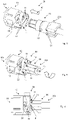
- Figures 1 and 2 12 show views of two complementary first and second connectors 10 and 20 according to an embodiment of a connector assembly of the present invention.
- figure 3 shows the in figure 2 connector 20 shown as a two-piece connector.
- the inside figure 3 Connector shown differs from the one in figure 2 connector shown only in that it is designed in two parts for better pluggability on eg cable and can be connected via connecting elements 23 to form a complete connector.
- the connecting elements 23 can be designed in different ways, as a snap connection, as a screw connection, they can be glued, welded or connected to one another in any other way, as long as the connector is firmly seated on the component.
- a first connector 10 is thus shown, which can be connected at a first end region 101 to an electrical component, for example a cable, a socket or another component.
- an electrical component for example a cable, a socket or another component.
- the first connector 10 can be connected to a second end region 202 of a second, in figure 2 shown, connector 20 are connected, which has a complementary to the first connector 10 shape.
- the body of the first connector 10 has insertion aids 12 and 13 for bringing the two connectors 10 and 20 together.
- the insertion aids 12 and 13 shown comprise insertion bevels 13 arranged opposite one another on the body of the first connector 10, which enable the bayonet-like closure, and a first guide means 12, which is arranged on the end face or end face of the first connector 10 as a recess in the circumference to Record guide lug 22 of a second connector 20 and lead into the insertion slope 13.
- the insertion aid 12 and 13 serves as the first part of a bayonet-like connection in conjunction with the complementary second part of the bayonet-like connection, which is shown in figure 2 correspondingly shown as guide lugs 22 .
- the second connector 20 shown can be connected at a first end region 201 to an electrical component, for example a cable will. At its second end area 202 it is formed in such a way that it can be connected to the first plug connector 10 .
- it is formed as a complementary connector to the first connector 10 in such a way that it has a second guide means 22 as the second part of the bayonet-like connection, which is designed as a guide lug 22 .
- the first and second connectors 10 and 20 are substantially cylindrical. However, any other suitable form can be used as long as the connection of the present invention can be done.
- FIG 1 two insertion bevels 13 and two first guide means 12 are shown. However, depending on the application, only one insertion bevel 13 and one first guide means 12 or more than two insertion bevels 13 or first guide means 12 can be provided. Accordingly, the second connector 20 is selected for connection to the first connector 10.
- the first guide means 12 shown are formed in such a way that they form a circumferential recess on the end face or end face of the first connector 10, so that a second guide means 22 complementary thereto, e.g. a guide lug, can be passed through and then guided into the insertion bevel 13 to become.
- the first guide means 12 formed as a recess has the advantage that, even in its end position, it does not protrude further out of the plug connector arrangement, or only protrudes slightly further than the second guide means 22 of the second plug connector 20, which is inserted via the bayonet-type connection.
- first connector 10 for secure fixing of the connection on its front side or face four first locking elements 11, of which two are arranged next to each other and the other two locking elements 11 opposite.
- the first latching elements 11 are arranged on the end face or end face or in the vicinity, ie at a small distance from the end face of the second end 102 of the first connector 10, in order to latch with corresponding, complementarily shaped second latching elements 21 of the second connector 20 in the plugging direction .
- the arrangement of the locking elements 11 depends on the application.
- the second plug connector 20 shown has a spaced-apart area from its second end area 202, on which the guide lugs 22 are arranged, to the in figure 1 shown locking recesses 11 complementary second locking elements 21, which are formed as locking lugs 21.
- the second latching elements 21 are so on the second connector in figure 2 arranged so that they are in the insertion direction, i.e. in the direction in which the first connector is brought together with or apart from the second connector (see reference number 40 in figure 4 ), With the first locking elements of the first connector 10 can engage.
- the shape of the latching elements 11 and 21 is chosen so that a firm connection with as little play as possible is formed after they have snapped into one another. Shapes such as triangles, trapezoids, nubs or other shapes can be selected that allow them to be locked together.
- the connector material is selected in such a way that it prevents intermodulation in high-frequency applications or is intermodulation-resistant. Furthermore, the material should have a certain elasticity, since elastic deformation and reshaping to the original shape of at least the guide element 22 embodied as a guide lug is necessary to avoid overtravel in the bayonet-type connection.
- a latching element can also be designed to be correspondingly elastic. This is useful when the guide lug 22 and locking lug 21 are arranged on the same connector. It is advantageous if the guide lug 22 is arranged closer to the second end region 202 of the connector than the latching lug 21, which in turn is arranged at a distance from the guide lug 22.
- the guide lugs 22 of the second connector 20 are inserted into the guide recesses 12 of the first connector 10. Then the connectors 10 and 20 are positioned relative to each other as in figure 5 shown rotated so that the guide lugs 22 are guided in the chamfers 13 until the locking elements 21 of the second connector 20 on the Face or face of the first connector 10 meet. this is in figure 6 shown. In figure 6 it can be seen that the guide lugs 22 have not yet reached their end position and the locking elements 11, 21 have not yet locked together. In order to get to the end position or to achieve locking, the two connectors are rotated further.
- the distance between the guide lugs 22 and the locking lugs 21 is stretched elastically by the material between the insertion bevel 13 and the end face or end face of the first connector 10, which corresponds to a wedge in the direction of rotation.
- the material of the second connector 20 can deform elastically back into its original shape, while the latching elements 21 latch with one another.
- a residual tension of the guide lugs 22 in the axial direction, ie in the insertion direction 40 can remain. Due to the elastic deformability of the guide lugs 22 and/or the latching elements 21, an overtravel inside the connectors 10, 20, ie in the electrically connected components, can be avoided, which leads to greater reliability.
- FIG 7 a connector assembly 30 is shown in which the first connector 10 has been brought together with the second connector 20 and the end position has been reached, ie the latching elements 11 and 21 are latched together. Due to the space-saving bayonet-like connection and the latching elements 11, 21 arranged accordingly in the insertion direction, the plug connector arrangement 30 requires very little space and is easy to assemble. Thus, multiple connector assemblies can be placed next to each other at a small distance, which in turn achieves cost savings.
Description
Die Erfindung betrifft eine Steckerverbinderanordnung.The invention relates to a male connector assembly.
Elektrische Steckverbindungen werden für vielseitige Anwendungen benötigt, z.B. als Verbindungen für Koaxialkabel bei Hochfrequenzanwendungen oder als Verbindung für andere Komponenten untereinander und mit Kabeln, z.B. im Automobilbereich. Problematisch bei der Verbindung ist, dass ein Lösen der beiden Steckverbindungen vermieden werden muss. Deshalb ist eine Vielzahl von Fixierungsmitteln bekannt, die ein Lösen der beiden Steckverbinder voneinander verhindern sollen. Eine feste Verbindung kann also über unterschiedlichste Fixierungsmittel erfolgen, z.B. über mehrere zusätzliche Hilfselemente, die mittels Drehbewegung eine Verbindung schaffen. Diese Verbindungsart wird bevorzugt bei zumindest annähernd zylindrischen Steckverbindern gewählt. Alternativ wird die Verbindung bei beispielsweise rechteckigen Steckverbindern über Schiebeelemente, die ineinander über Federelemente einrasten, erzielt.Electrical plug-in connections are required for a wide range of applications, e.g. as connections for coaxial cables in high-frequency applications or as connections for other components to one another and to cables, e.g. in the automotive sector. The problem with the connection is that loosening of the two plug connections must be avoided. Therefore, a large number of fixing means are known which are intended to prevent the two connectors from becoming detached from one another. A fixed connection can therefore be made using a wide variety of fixing means, e.g. using several additional auxiliary elements that create a connection by means of a rotary movement. This type of connection is preferably selected for at least approximately cylindrical connectors. Alternatively, in the case of rectangular plug connectors, for example, the connection is achieved via sliding elements which snap into one another via spring elements.
Unterschiedliche Fixierungsmittel zur Fixierung von Steckern werden in der
Die
Die bisher vorgeschlagenen Steckverbindungsanordnungen können für moderne Hochfrequenzanwendungen nur bedingt verwendet werden, da sie entweder eine große Anzahl von Teilen benötigen oder einen zu hohen Platzbedarf haben. Bei Lösungen mit mehreren Teilen besteht das Problem, dass diese Teile aufgrund ihrer Anzahl alleine kostenintensiv sind. Außerdem besteht die Gefahr, dass Intermodulationen entstehen können, wenn die Teile nicht genau aufeinander abgestimmt sind oder nicht intermodulationsfreies Material verwendet wird, um Verschleiß zu verhindern. Außerdem ist die Montage der Teile aufwändig und damit kostenintensiv. Bei Lösungen, die eine geringere Anzahl von Teilen benötigen, besteht das Problem, dass die beispielsweise aufgrund eines zur Verbindung benötigten Drehrings einen gewissen Platzbedarf haben, so dass mehrere Steckverbindungen nicht in geringem Abstand zueinander nebeneinander angeordnet werden können, was wiederum Kosten verursacht.The previously proposed connector arrangements can only be used to a limited extent for modern high-frequency applications, since they either require a large number of parts or have too much space. In the case of solutions with several parts, there is the problem that these parts alone are cost-intensive because of their number. There is also a risk that intermodulation can occur if the parts are not precisely matched or if intermodulation-free material is not used to prevent wear. In addition, the assembly of the parts is complex and therefore expensive. With solutions that require a smaller number of parts, there is the problem that they require a certain amount of space, for example due to a rotary ring required for the connection, so that several plug connections cannot be arranged next to one another at a small distance from one another, which in turn causes costs.
Deshalb ist es eine Aufgabe dieser Erfindung, zueinander passende Steckverbinder einer Steckerverbinderanordnung bereitzustellen, durch welche die oben genannten Probleme gelöst werden. Vor allem soll eine Miniaturisierung der Steckverbinder bzw. des Gesamtsystems der Steckerverbinderanordnung realisiert werden. Diese Aufgabe wird erfindungsgemäß durch die Merkmale des unabhängigen Patentanspruchs gelöst. Vorteilhafte Ausgestaltungen sind Gegenstand der abhängigen Ansprüche.It is therefore an object of this invention to provide mating connectors of a connector assembly which solve the above problems. Above all, miniaturization of the plug connectors or the overall system of the plug connector arrangement is to be implemented. This object is achieved according to the invention by the features of the independent patent claim. Advantageous configurations are the subject matter of the dependent claims.
Vorgeschlagen wird erfindungsgemäß eine Steckerverbinderanordnung nach Anspruch 1 mit einem erste Steckverbinder, der dazu eingerichtet ist, mit einem ersten Ende mit einer ersten elektrischen Komponente verbunden zu werden und mit einem zweiten Ende mit einem zum ersten Steckverbinder komplementären zweiten Steckverbinder verbunden zu werden, wobei der erste Steckverbinder zumindest einen ersten Teil einer bajonettartigen Verbindung und zumindest ein erstes Rastelement einer Rasteinrichtung umfasst, das derart angeordnet ist, dass es sich in eine Steckrichtung erstreckt.According to the invention, a plug connector arrangement according to claim 1 is proposed with a first plug connector, which is designed to be connected at a first end to a first electrical component and to be connected at a second end to a second plug connector that is complementary to the first plug connector, the first Connector comprises at least a first part of a bayonet-like connection and at least a first locking element of a locking device, which is arranged such that it extends in a plug-in direction.
Durch die Bereitstellung der Kombination aus bajonettartiger Verbindung und Rastelement, das in Steckrichtung angeordnet ist, werden keine zusätzlichen Elemente wie Schieber oder Adapter zu Fixierung des Steckverbinders benötigt.By providing the combination of bayonet-type connection and latching element, which is arranged in the plug-in direction, no additional elements such as slides or adapters are required to fix the connector.
Außerdem ist es durch die Anordnung des Rastelements in Steckrichtung möglich, einen komplementären zweiten Steckverbinder mit dem ersten Steckverbinder so zu verbinden, dass eine minimale Dimensionierung beider Steckverbinder möglich ist und dadurch mehrere Steckverbinderanordnungen sehr nah nebeneinander angeordnet werden können.In addition, the arrangement of the latching element in the insertion direction makes it possible to connect a complementary second connector to the first connector in such a way that both connectors can be dimensioned to a minimum, and as a result several connector arrangements can be arranged very close to one another.
Unter einer bajonettartigen Verbindung wird eine Verbindung verstanden, bei der einer der beiden Steckverbinder zumindest eine bezüglich der Steckrichtung schräg verlaufende Einführschräge mit einem ersten Führungsmittel aufweist und der andere der beiden Steckverbinder ein über das erste Führungsmittel in die Einführschräge passendes zweites Führungsmittel aufweist. Durch Einführen des zweiten Führungsmittels in die Einführschräge über das erste Führungsmittel und Drehen des zweiten Führungsmittels entlang der Einführschräge erfolgt je nach Bewegungsrichtung ein Zusammenführen bzw. ein Auseinanderführen der beiden Steckverbinder. Anders als bei Bajonettverbindungen wird bei einer bajonettartigen Verbindung kein Überhub benötigt bzw. verwendet. Unter Überhub wird ein Einschnappen des Führungsmittels in eine Ausbuchtung in der Einführschräge bezeichnet, wodurch ein einfaches Herausbewegen des Führungsmittels aus dem Endbereich der Einführschräge nicht ohne Krafteinwirkung erfolgen kann. Nachteilig an einem Überhub ist, dass zum Lösen der Verbindung eine axiale Bewegung der Steckverbinder aufeinander zu erfolgen muss, so dass ein nicht vorteilhaftes mehrfaches Überfahren des elektrischen Kontaktes erfolgt.A bayonet-type connection is understood to be a connection in which one of the two connectors has at least one insertion bevel with a first guide means and the other of the two connectors has a second guide means that fits into the insertion bevel via the first guide means. By inserting the second guide into the insertion bevel via the first guide and rotating the second guide along the insertion bevel, the two connectors are brought together or separated, depending on the direction of movement. Unlike bayonet connections, no overtravel is required or used with a bayonet-type connection. Overtravel refers to the guide means snapping into a bulge in the insertion bevel, as a result of which the guide means cannot simply be moved out of the end region of the insertion bevel without the application of force. The disadvantage of an overtravel is that in order to release the connection, the plug connectors have to move axially towards one another, so that the electrical contact is passed over several times, which is not advantageous.
In der erfindungsgemäßen Ausführung ist vorgesehen, dass der erste Teil der bajonettartigen Verbindung als eine zwischen dem ersten Ende und dem zweiten Ende angeordnete, zu einer Steckrichtung des Steckverbinders schräg verlaufende Einführschräge gebildet ist und das erste Rastelement an der Stirnfläche des zweiten Endes des ersten Steckverbinders angeordnet ist.In the embodiment according to the invention, it is provided that the first part of the bayonet-like connection is formed as an insertion bevel arranged between the first end and the second end and running obliquely to a plug-in direction of the connector, and the first latching element is arranged on the end face of the second end of the first connector is.
Die Anordnung des ersten Rastelements an dem Steckverbinder gibt vor, welcher zweite Steckverbinder mit dem ersten Steckverbinder verbunden werden kann. Durch das entsprechend angeordnete erste Rastelement wird eine Miniaturisierung sowohl der Steckverbinder als auch der aus zwei komplementären miteinander verbundenen Steckverbindern erzeugten Steckverbinderanordnung erreicht.The arrangement of the first latching element on the connector specifies which second connector can be connected to the first connector. Due to the correspondingly arranged first latching element, a miniaturization of both the plug connector and the plug connector arrangement produced from two complementary plug connectors connected to one another is achieved.
Durch eine entsprechende Anordnung des ersten Teils und des Rastelements zueinander und zum zweiten Ende des Steckverbinders wird sichergestellt, dass beim Zusammenführen oder Auseinanderführen von zwei Steckverbindern kein Überhub entsteht.A corresponding arrangement of the first part and the locking element to each other and to the second end of the connector ensures that when There is no overtravel when two connectors are brought together or separated.
In einer weiteren Ausführung ist vorgesehen, dass das erste Rastelement eine Rastausnehmung oder eine Rastnase ist.In a further embodiment it is provided that the first latching element is a latching recess or a latching lug.
In einer weiteren Ausführung ist vorgesehen, dass der erste Steckverbinder zumindest zwei erste Teile einer bajonettartigen Verbindung umfasst. In einer weiteren Ausführung ist vorgesehen, dass der erste Steckverbinder zumindest zwei erste Rastelemente umfasst. In einer weiteren Ausführung sind die zumindest zwei ersten Rastelemente symmetrisch zueinander angeordnet.In a further embodiment it is provided that the first connector comprises at least two first parts of a bayonet-type connection. In a further embodiment it is provided that the first connector comprises at least two first latching elements. In a further embodiment, the at least two first latching elements are arranged symmetrically to one another.
Durch die Bereitstellung von mehreren ersten Teilen der bajonettartigen Verbindung und/oder mehreren Rastelementen, die als Rastausnehmungen, Rastnasen oder einer Kombination daraus gebildet sind, wird eine noch bessere Fixierung von Steckverbindern ermöglicht.The provision of a plurality of first parts of the bayonet-type connection and/or a plurality of latching elements, which are formed as latching recesses, latching lugs or a combination thereof, enables connectors to be fixed in place even better.
Die Steckverbinderanordnung weist des Weiteren einen zweiten Steckverbinder auf, der zu dem ersten Steckverbinder komplementär und damit in Steckverbindung bringbar ist, und der dazu eingerichtet ist, mit einem ersten Endbereich mit einer zweiten elektrischen Komponente verbunden zu werden und mit einem zweiten Endbereich mit dem ersten Steckverbinder verbunden zu werden. Der zweite Steckverbinder umfasst zumindest einen zweiten zu dem ersten Steckverbinder komplementären Teil einer bajonettartigen Verbindung, und zumindest ein zweites Rastelement einer Rasteinrichtung, das derart angeordnet ist, dass es sich in eine Steckrichtung erstreckt, wobei das zumindest eine zweite Rastelement eine zu der Form des ersten Rastelements komplementäre Form aufweist.The connector arrangement also has a second connector, which is complementary to the first connector and can be plugged into it, and which is set up to be connected to a second electrical component with a first end area and to the first connector with a second end area to be connected. The second connector comprises at least a second part of a bayonet-type connection that is complementary to the first connector, and at least one second latching element of a latching device, which is arranged in such a way that it extends in a plugging direction, the at least one second latching element having a shape that matches that of the first Has locking element complementary shape.
In der erfindungsgemäßen Ausführung ist vorgesehen, dass der zweite Teil der bajonettartigen Verbindung an dem zweiten Ende des zweiten Steckverbinders als zweites Führungsmittel angeordnet ist und das zweite Rastelement zu dem zweiten Teil der bajonettartigen Verbindung in Richtung erstes Ende des zweiten Steckverbinders beabstandet angeordnet ist.In the embodiment according to the invention it is provided that the second part of the bayonet-like connection is arranged at the second end of the second connector as a second guide means and the second latching element is arranged at a distance from the second part of the bayonet-like connection in the direction of the first end of the second connector.
Der zweite Steckverbinder ist komplementär zu dem ersten Steckverbinder aufgebaut und weist damit dieselben Vorteile auf, vor allem, dass eine Miniaturisierung des Gesamtsystems aus erstem und zweitem Stecker erzielt werden kann.The second connector is designed to complement the first connector and thus has the same advantages, above all that miniaturization of the overall system made up of the first and second connectors can be achieved.
Vorgesehen ist im Rahmen der vorliegenden Erfindung ferner, dass der erste und/oder der zweite Steckverbinder einstückig, zweistückig oder mehrstückig ausgebildet ist bzw. sind.It is also provided within the scope of the present invention that the first and/or the second plug connector is/are formed in one piece, in two pieces or in several pieces.
Ein einstückig ausgebildeter Steckverbinder ist sehr kostengünstig, während ein zweistückig ausgebildeter Steckverbinder den Vorteil hat, dass die Montage auf der entsprechenden Komponente, z.B. einem Kabel, vereinfacht werden kann. Es besteht auch die Möglichkeit, den Steckverbinder mehrstückig auszubilden, wenn nötig. Welcher Steckverbinder gewählt wird hängt von der Anwendung ab.A one-piece connector is very inexpensive, while a two-piece connector has the advantage that assembly on the corresponding component, e.g., a cable, can be simplified. There is also the possibility of constructing the connector in several pieces, if necessary. Which connector is chosen depends on the application.
In einer Ausführungsform sind der erste Teil der bajonettartigen Verbindung und der zweite Teil der bajonettartigen Verbindung derart komplementär zueinander gebildet und angeordnet, dass dadurch der erste Steckverbinder mit dem zweiten Steckverbinder zusammengeführt bzw. auseinandergeführt werden kann. Das erste Rastelement und das zweite Rastelement sind derart komplementär zueinander gebildet und angeordnet, dass das erste Rastelement mit dem zweiten Rastelement in einer Stellung verrastet, in der sich die beiden Steckverbinder in einer Endposition der bajonettartigen Verbindung befinden.In one embodiment, the first part of the bayonet-like connection and the second part of the bayonet-like connection are formed and arranged so as to complement one another in such a way that the first connector can be brought together with or separated from the second connector. The first latching element and the second latching element are formed and arranged so as to complement one another in such a way that the first latching element latches with the second latching element in a position in which the two connectors are in an end position of the bayonet-like connection.
Durch die Steckverbinderanordnung aus erstem und zweitem Steckverbinder wird eine Miniaturisierung der Steckverbinderanordnung erzielt, so dass mehrere Steckverbinderanordnungen eng nebeneinander und einfach zu montieren angeordnet werden können. Die Steckverbinderanordnung vereint alle Vorteile der einzelnen Steckverbinder.The connector arrangement made up of the first and second connectors results in a miniaturization of the connector arrangement, so that a plurality of connector arrangements can be arranged close to one another and are easy to assemble. The connector arrangement combines all the advantages of the individual connectors.
In einer weiteren Ausführung ist vorgesehen, dass, wenn der erste Teil der bajonettartigen Verbindung als Führungsnase ausgebildet ist, und das erste Rastelement als Rastnase ausgebildet ist, ein elastisches Verformen der Führungsnase und/oder der Rastnase und/oder des Materials des Steckverbinders beim Zusammenführen oder beim Auseinanderführen der Steckverbinder in oder gegen die Steckrichtung erfolgt, wobei die Verformung reversibel ist.In a further embodiment it is provided that when the first part of the bayonet-type connection is designed as a guide lug and the first locking element is designed as a locking lug, elastic deformation of the guide lug and/or the locking lug and/or the material of the plug connector when they are brought together or takes place when the connector is pulled apart in or against the plug-in direction, with the deformation being reversible.
Durch das elastische Verformen kann beim Zusammenführen oder Auseinanderführen ein Überhub vermieden werden. Ferner wird durch die Reversibilität ein zusätzlicher Schutz vor einem Herausgleiten aus der bajonettartigen Verbindung vermieden.Due to the elastic deformation, an overtravel can be avoided when bringing them together or moving them apart. Furthermore, the reversibility avoids additional protection against slipping out of the bayonet-type connection.
Weitere Merkmale und Vorteile der Erfindung ergeben sich aus der nachfolgenden Beschreibung von Ausführungsbeispielen der Erfindung, anhand der Figuren der Zeichnung, die erfindungsgemäße Einzelheiten zeigt, und aus den Ansprüchen.Further features and advantages of the invention result from the following description of exemplary embodiments of the invention, with reference to the figures in FIG Drawing showing details of the invention and from the claims.
Bevorzugte Ausführungsformen der Erfindung werden nachfolgend anhand der beigefügten Zeichnung näher erläutert.
-
Fig. 1 zeigt eine Ansicht eines Steckverbinders gemäß einer Ausführung einer Steckerverbinderanordnung der vorliegenden Erfindung. -
Fig. 2 zeigt eine Ansicht eines zu einem inFigur 1 gezeigten Steckverbinder komplementären Steckverbinders gemäß einer Ausführung einer Steckerverbinderanordnung der vorliegenden Erfindung. -
Fig. 3 zeigt eine Ansicht eines inFigur 2 gezeigten, zweiteilig ausgebildeten Steckverbinders gemäß einer Ausführung der vorliegenden Erfindung. -
Fig. 4 zeigt eine Ansicht eines Zusammenführens des ersten und des zweiten Steckverbinders gemäß einer Ausführung der vorliegenden Erfindung. -
Fig. 5 zeigt eine Ansicht eines Zusammenführens und Drehens des ersten und des zweiten Steckverbinders gemäß einer Ausführung der vorliegenden Erfindung. -
Fig. 6 zeigt eine Ansicht eines Zusammenführens und Drehens bis kurz vor der Endposition des ersten und des zweiten Steckverbinders gemäß einer Ausführung der vorliegenden Erfindung. -
Fig. 7 zeigt eine Ansicht einer Steckerverbinderanordnung in Endposition gemäß einer Ausführung der vorliegenden Erfindung.
-
1 12 is a view of a connector according to an embodiment of a connector assembly of the present invention. -
2 shows a view one to one infigure 1 shown connector complementary connector according to an embodiment of a connector assembly of the present invention. -
3 shows a view of an infigure 2 shown, two-piece connector according to an embodiment of the present invention. -
4 12 is a view of mating the first and second connectors according to an embodiment of the present invention. -
figure 5 Fig. 12 shows a mating and rotating view of the first and second connectors according to an embodiment of the present invention. -
6 Fig. 12 shows a view of bringing together and rotating to just before the final position of the first and second connectors according to an embodiment of the present invention. -
7 Figure 12 shows a final position view of a male connector assembly according to an embodiment of the present invention.
In den nachfolgenden Figurenbeschreibungen sind gleiche Elemente bzw. Funktionen mit gleichen Bezugszeichen versehen.In the following descriptions of the figures, the same elements or functions are provided with the same reference symbols.
Der in
In der nachfolgenden Beschreibung wird der in
In
Dazu weist der Körper des ersten Steckverbinders 10 Einführhilfen 12 und 13 zum Zusammenführen der beiden Steckverbinder 10 und 20 auf. Die in
Der in
In dem in
In
Das bzw. die in
Zusätzlich zu der platzsparenden bajonettartigen Verbindung weist der in
Der in
Die Form der Rastelemente 11 und 21 wird so gewählt, dass eine feste, möglichst spielfreie Verbindung nach dem Einrasten ineinander entsteht. Es können Formen wie Dreiecke, Trapeze, Noppen oder andere Formen gewählt werden, die ein Verrasten miteinander ermöglichen. Vorteilhaft ist die Wahl von einfach herzustellenden Formen, z.B. durch Spritzgießen.The shape of the latching
Das Material der Steckverbinder ist derart gewählt, dass es bei HochfrequenzAnwendungen Intermodulation verhindert bzw. intermodulationsfest ist. Ferner sollte das Material eine gewisse Elastizität aufweisen, da zur Vermeidung eines Überhubs bei der bajonettartigen Verbindung ein elastisches Verformen und Rückformen zur Ursprungsform von zumindest dem als Führungsnase ausgebildeten Führungselement 22 erforderlich ist. Ebenso kann auch ein Rastelement entsprechend elastisch ausgebildet sein. Dies bietet sich an, wenn Führungsnase 22 und Rastnase 21 an demselben Steckverbinder angeordnet sind. Dabei ist es vorteilhaft, wenn die Führungsnase 22 näher an dem zweiten Endbereich 202 des Steckverbinders angeordnet ist als die Rastnase 21, die wiederum in einem Abstand zu der Führungsnase 22 angeordnet ist. Beim Zusammenführen der beiden Steckverbinder, wie in
In
Das Lösen der Steckerverbinderanordnung erfolgt, indem der Vorgang des Zusammenführens umgekehrt ausgeführt wird. Mittels Kraftaufwand, der durch die entsprechende Wahl der Schrägen der Rastelemente 11 bzw. 21 bestimmt wird, kann die Verrastung gelöst werden. Durch die elastische Verformbarkeit der Führungsmittel 22 bzw. Ratselemente 21 und/oder des Materials des Steckverbinders erfolgt auch beim Lösen der Steckerverbinderanordnung kein Überhub an den elektrischen Komponenten.Release of the male connector assembly is accomplished by reversing the mating operation. By applying force, which is determined by the appropriate selection of the bevels of the locking
Durch das axiale Zusammenführen der Steckverbinder ist ein minimaler Platzbedarf Realisiert, ohne dabei die sichere Fixierung der Steckverbinder zu gefährden.Due to the fact that the connectors are brought together axially, a minimum of space is required without jeopardizing the secure fixing of the connectors.
- 1010
- Erster SteckverbinderFirst connector
- 101101
- Erstes EndeFirst ending
- 102102
- Zweites Endesecond ending
- 1111
- Erstes RastelementFirst locking element
- 1212
- Erstes FührungsmittelFirst guide
- 1313
- Einführschrägelead-in bevel
- 2020
- Zweiter SteckverbinderSecond connector
- 201201
- Erster EndbereichFirst end area
- 202202
- Zweiter EndbereichSecond end area
- 2121
- Zweites RastelementSecond locking element
- 2222
- Zweiter Teil der bajonettartigen Verbindung bzw. Zweites FührungsmittelSecond part of the bayonet-like connection or second guide means
- 2323
- Verbindungselementefasteners
- 3030
- Steckerverbinderanordnungconnector assembly
- 4040
- Steckrichtungmating direction
Claims (8)
- A plug connector arrangement (30), comprising a first plug connector (10) and a second plug connector (20) which is designed to be complementary to the first plug connector (10), wherein the first plug connector (10) is configured to be connected to a first electrical component with a first end (101) and to be connected to the second plug connector (20) with a second end (102), and wherein the second plug connector (20) is configured to be connected to a second electrical component with a first end (201) and to be connected to the first plug connector (10) with a second end (202), wherein the first plug connector (10) comprises:- at least one first part (12, 13) of a bayonet-like connection, wherein the first part (12, 13) of the bayonet-like connection is configured as an insertion bevel (13) arranged between the first end (101) and the second end (102) and extending obliquely with respect to a plug-in direction (40) of the plug connector (10), and as a first guide means (12) which extends along the plug-in direction (40) on the end face of the second end (102),- at least one first latching element (11) of a latching device which is arranged on the end face of the second end (102) of the first plug-in connector (10) and which is arranged in such a way that it extends in a plug-in direction (40), wherein the first guide means (12) and the first latching element (11) are arranged at different positions of the end face,wherein the second plug connector (20) comprises- at least one second part (22) of a bayonet-like connection which is configured and arranged in such a way that it is in engagement with the insertion bevel (13) of the first plug-in connector (10) after connection,- at least one second latching element (21) which is arranged at a distance to the end face of the second end (202) of the second plug connector (20) in a direction of the first end (201) and which is arranged in such a way that, after the second plug connector (20) has been connected to the first plug connector (10), it is latched with the corresponding first latching element (11) of the first plug connector (10),
characterized in thatthe bayonet-like connection has no overstroke, so that when the second part (22) of the bayonet-like connection of the second plug connector (20) is inserted into the insertion bevel (13) via the first guide means (12) and moved along the insertion bevel (13), the second part (22) is not snapped into a bulge of the insertion bevel (13), and in thatthe second latching element (21) of the second plug connector and/or the second part (22) of the bayonet-like connection of the second plug connector and/or the first plug connector (10) and/or the second plug connector (20) is formed of an elastic material. - The plug connector arrangement (30) according to one of the preceding claims, wherein the first latching element (11) is a latching recess (11) or a latching lug.
- The plug connector arrangement (30) according to one of the preceding claims, wherein the first plug connector (10) comprises at least two first latching elements (11).
- The plug connector arrangement (30) according to claim 3, wherein the at least two first latching elements (11) are arranged symmetrically with respect to one another.
- The plug connector arrangement (30) according to one of claims 1 to 4, wherein the first plug connector (10, 20) is formed in one piece, in two pieces or in multiple pieces.
- The plug connector arrangement (30) according to one of the preceding claims, wherein the second plug connector (20) is formed in one piece, in two pieces or in multiple pieces.
- The plug connector arrangement (30) according to one of the preceding claims, wherein- the first part (12, 13) of the bayonet-like connection and the second part (22) of the bayonet-like connection are formed and arranged in a complementary manner to each other so that the first plug connector (10) and the second plug connector (20) can be brought together and moved apart from one another, and- the first latching element (11) and the second latching element (21) are formed and arranged in a complementary manner to each other so that the first latching element (11) latches with the second latching element (21) in a position in which the two plug connectors (10, 20) are located in an end position of the bayonet-like connection (12, 13, 22).
- The plug connector arrangement (30) according to claim 7, wherein the second
guide means (22) of the bayonet-like connection is configured as a guiding lug and the second latching element (21) is configured as a latching lug, wherein the guiding lug (22) and/or the latching lug (21) and/or the material of the plug connector (10, 20) is elastically deformed when bringing together or moving apart from one another the plug connectors (10, 20) in or against the plug-in direction (40), wherein the deformation is reversible.
Applications Claiming Priority (1)
| Application Number | Priority Date | Filing Date | Title |
|---|---|---|---|
| DE102015120921.7A DE102015120921B4 (en) | 2015-12-02 | 2015-12-02 | Connector and plug connector assembly |
Publications (2)
| Publication Number | Publication Date |
|---|---|
| EP3176885A1 EP3176885A1 (en) | 2017-06-07 |
| EP3176885B1 true EP3176885B1 (en) | 2022-03-30 |
Family
ID=56855357
Family Applications (1)
| Application Number | Title | Priority Date | Filing Date |
|---|---|---|---|
| EP16187168.6A Active EP3176885B1 (en) | 2015-12-02 | 2016-09-05 | Connector assembly |
Country Status (4)
| Country | Link |
|---|---|
| US (1) | US9859652B2 (en) |
| EP (1) | EP3176885B1 (en) |
| CN (1) | CN106921088B (en) |
| DE (1) | DE102015120921B4 (en) |
Families Citing this family (7)
| Publication number | Priority date | Publication date | Assignee | Title |
|---|---|---|---|---|
| EP3257110B1 (en) * | 2015-02-13 | 2020-12-02 | TBi Industries GmbH | Coupling for power cables |
| CN108988003A (en) * | 2018-09-03 | 2018-12-11 | 深圳澳华电气股份有限公司 | Self-locking water-proof connector |
| DE102018131561A1 (en) * | 2018-12-10 | 2020-06-10 | Harting Electric Gmbh & Co. Kg | Contact carrier for contact element and contact element |
| CN111370899B (en) * | 2020-04-03 | 2022-04-12 | 昆山电科速联电子科技有限公司 | Buckle type electronic connector |
| CN111740237A (en) * | 2020-07-20 | 2020-10-02 | 江苏英曼电子工业有限公司 | Spiral locking device |
| CN113629451B (en) * | 2021-07-20 | 2024-04-16 | 中航光电科技股份有限公司 | Connector secondary locking mechanism, plug and connector assembly |
| DE102021129803A1 (en) * | 2021-11-16 | 2023-05-17 | Zumtobel Lighting Gmbh | Contacting element for connecting an electrical or electronic module to an elongated light mounting rail |
Citations (3)
| Publication number | Priority date | Publication date | Assignee | Title |
|---|---|---|---|---|
| FR1188157A (en) * | 1957-12-06 | 1959-09-21 | Souriau & Cie | Improvements to power outlets |
| US3805379A (en) * | 1971-10-26 | 1974-04-23 | Trw Inc | Method of assembling an electrical connector to effect a preloading thereof |
| US4059324A (en) * | 1976-09-15 | 1977-11-22 | The Bendix Corporation | Electrical connector |
Family Cites Families (23)
| Publication number | Priority date | Publication date | Assignee | Title |
|---|---|---|---|---|
| US4477864A (en) * | 1982-07-15 | 1984-10-16 | General Motors Corporation | Lamp assembly |
| US4758181A (en) * | 1987-07-27 | 1988-07-19 | General Motors Corporation | Locking arrangement for a lamp socket assembly |
| DE9003016U1 (en) * | 1990-03-12 | 1991-07-11 | Grote & Hartmann Gmbh & Co Kg, 5600 Wuppertal, De | |
| DE9105436U1 (en) | 1991-05-02 | 1991-06-13 | Amp Inc., Harrisburg, Pa., Us | |
| US5209678A (en) * | 1992-01-09 | 1993-05-11 | Telect, Inc. | Telecommunications front access coaxial jack and plug assembly with releasable locking feature |
| US6206714B1 (en) * | 1999-02-01 | 2001-03-27 | Litton Systems, Inc. | Plug and adapter for existing single pole electrical receptacle |
| JP3687728B2 (en) * | 1999-08-02 | 2005-08-24 | 矢崎総業株式会社 | Electric connector housing and fitting detection method thereof |
| US6226068B1 (en) * | 1999-08-27 | 2001-05-01 | Amphenol Corporation | Self-locking bayonet coupling mechanism |
| EP1617524A1 (en) | 2004-07-14 | 2006-01-18 | Coninvers Elektrotechnische Bauelemente GmbH | Electrical connector |
| EP2104186A1 (en) * | 2008-03-21 | 2009-09-23 | Bocchiotti S.p.A. Societa' per l'Industria Elettrotecnica | Body for electrical socket or plug |
| DE102008061934B4 (en) * | 2008-12-12 | 2011-02-24 | Tyco Electronics Amp Gmbh | High Power Connectors |
| US9061367B2 (en) * | 2010-04-13 | 2015-06-23 | Illinois Tool Works Inc. | Weld electrical and gas connector with sealed gas flow |
| DE102010021303B4 (en) * | 2010-04-28 | 2019-01-17 | Amphenol-Tuchel Electronics Gmbh | Electrical connector, in particular round connector |
| CH703180A1 (en) * | 2010-06-11 | 2011-12-15 | Multi Holding Ag | Plug connection for the transmission of electric energy. |
| KR101132375B1 (en) * | 2012-01-11 | 2012-04-03 | 배복만 | Fixing structure of coaxial cable connector |
| JP2015111962A (en) | 2012-03-27 | 2015-06-18 | シャープ株式会社 | Parallel operation power supply system |
| CN104904074B (en) * | 2012-11-12 | 2016-12-14 | 德尔福国际业务卢森堡公司 | There is the connector assembly of automatic auxiliary lock |
| JP2014241265A (en) * | 2013-06-12 | 2014-12-25 | ファナック株式会社 | Electric connector capable of selecting engagement system, and electric motor with electric connector |
| JP6106544B2 (en) * | 2013-07-02 | 2017-04-05 | 矢崎総業株式会社 | Rotary connector |
| JP6031006B2 (en) * | 2013-07-02 | 2016-11-24 | 矢崎総業株式会社 | Terminal fitting connection structure and rotation fitting type connector |
| JP2015076296A (en) * | 2013-10-10 | 2015-04-20 | Smk株式会社 | Terminal locking structure of connector |
| US9477049B2 (en) | 2013-12-20 | 2016-10-25 | Senko Advanced Components, Inc. | Lockable connectors and connection assemblies |
| US9543677B1 (en) * | 2015-07-29 | 2017-01-10 | Stein Industries Inc. | Quick connector |
-
2015
- 2015-12-02 DE DE102015120921.7A patent/DE102015120921B4/en active Active
-
2016
- 2016-09-05 EP EP16187168.6A patent/EP3176885B1/en active Active
- 2016-10-11 CN CN201610886117.3A patent/CN106921088B/en active Active
- 2016-10-25 US US15/333,917 patent/US9859652B2/en active Active
Patent Citations (3)
| Publication number | Priority date | Publication date | Assignee | Title |
|---|---|---|---|---|
| FR1188157A (en) * | 1957-12-06 | 1959-09-21 | Souriau & Cie | Improvements to power outlets |
| US3805379A (en) * | 1971-10-26 | 1974-04-23 | Trw Inc | Method of assembling an electrical connector to effect a preloading thereof |
| US4059324A (en) * | 1976-09-15 | 1977-11-22 | The Bendix Corporation | Electrical connector |
Also Published As
| Publication number | Publication date |
|---|---|
| EP3176885A1 (en) | 2017-06-07 |
| CN106921088B (en) | 2019-08-09 |
| DE102015120921B4 (en) | 2017-10-19 |
| US9859652B2 (en) | 2018-01-02 |
| US20170162981A1 (en) | 2017-06-08 |
| CN106921088A (en) | 2017-07-04 |
| DE102015120921A1 (en) | 2017-06-08 |
Similar Documents
| Publication | Publication Date | Title |
|---|---|---|
| EP3176885B1 (en) | Connector assembly | |
| EP2076943B1 (en) | Xlr connector | |
| EP1796225B1 (en) | Device for an axial sliding connector ending-cable to a connector housing | |
| EP3937313B1 (en) | Electric plug connector | |
| EP3476009B1 (en) | Connector | |
| EP3259810B1 (en) | Connector with damping element | |
| DE102014110466B4 (en) | Connector with a low-wear sealing function and a device consisting of a connector and a mating connector | |
| EP0847604B1 (en) | Electrical connector with contact securing slide | |
| EP1362393A1 (en) | Plug connector having a housing and a clamping insert | |
| DE19920481C1 (en) | Self-locking electrical connector, especially for automotive applications | |
| DE102019114257B4 (en) | Connector with locking system | |
| WO2017009286A1 (en) | Multipolar electric plug connector part, and plug connector arrangement | |
| EP3665748B1 (en) | Electrical connector part having a locking element | |
| EP3756249B1 (en) | Plug connector comprising polarisation element, and system and method for mounting, for plugging. and for separating said plug connector | |
| EP3403298B1 (en) | Plug connector | |
| EP3713018B1 (en) | Electric connector | |
| DE102019114262B3 (en) | Connector with locking system | |
| EP3790121A1 (en) | Connector and connector system | |
| DE10326834B4 (en) | Connectors | |
| EP2587595B1 (en) | Plug-in connection and method for operating a plug-in connection for high voltage applications | |
| DE102008006046A1 (en) | Electrical plug and socket device, has contact bushes and/or contact pins conducted and/or fixed in receptacles in its axis-proximate operating positions by leading angles during joining of contact support and collar part | |
| DE10346367B4 (en) | Freely rotatable HF-angle connector | |
| DE102021119480B3 (en) | Electrical connector and Electrical connector system | |
| EP3345261B1 (en) | Contact carrier | |
| DE102021118012A1 (en) | Connector with selectable release |
Legal Events
| Date | Code | Title | Description |
|---|---|---|---|
| 17P | Request for examination filed |
Effective date: 20160905 |
|
| AK | Designated contracting states |
Kind code of ref document: A1 Designated state(s): AL AT BE BG CH CY CZ DE DK EE ES FI FR GB GR HR HU IE IS IT LI LT LU LV MC MK MT NL NO PL PT RO RS SE SI SK SM TR |
|
| AX | Request for extension of the european patent |
Extension state: BA ME |
|
| PUAI | Public reference made under article 153(3) epc to a published international application that has entered the european phase |
Free format text: ORIGINAL CODE: 0009012 |
|
| STAA | Information on the status of an ep patent application or granted ep patent |
Free format text: STATUS: REQUEST FOR EXAMINATION WAS MADE |
|
| STAA | Information on the status of an ep patent application or granted ep patent |
Free format text: STATUS: EXAMINATION IS IN PROGRESS |
|
| 17Q | First examination report despatched |
Effective date: 20180523 |
|
| RAP1 | Party data changed (applicant data changed or rights of an application transferred) |
Owner name: KATHREIN SE |
|
| RAP1 | Party data changed (applicant data changed or rights of an application transferred) |
Owner name: ERICSSON AB |
|
| RAP1 | Party data changed (applicant data changed or rights of an application transferred) |
Owner name: TELEFONAKTIEBOLAGET LM ERICSSON (PUBL) |
|
| STAA | Information on the status of an ep patent application or granted ep patent |
Free format text: STATUS: EXAMINATION IS IN PROGRESS |
|
| GRAP | Despatch of communication of intention to grant a patent |
Free format text: ORIGINAL CODE: EPIDOSNIGR1 |
|
| STAA | Information on the status of an ep patent application or granted ep patent |
Free format text: STATUS: GRANT OF PATENT IS INTENDED |
|
| RIC1 | Information provided on ipc code assigned before grant |
Ipc: H01R 24/00 20110101AFI20210604BHEP Ipc: H01R 24/40 20110101ALI20210604BHEP Ipc: H01R 13/625 20060101ALI20210604BHEP Ipc: H01R 13/627 20060101ALI20210604BHEP |
|
| INTG | Intention to grant announced |
Effective date: 20210623 |
|
| GRAJ | Information related to disapproval of communication of intention to grant by the applicant or resumption of examination proceedings by the epo deleted |
Free format text: ORIGINAL CODE: EPIDOSDIGR1 |
|
| STAA | Information on the status of an ep patent application or granted ep patent |
Free format text: STATUS: EXAMINATION IS IN PROGRESS |
|
| GRAP | Despatch of communication of intention to grant a patent |
Free format text: ORIGINAL CODE: EPIDOSNIGR1 |
|
| STAA | Information on the status of an ep patent application or granted ep patent |
Free format text: STATUS: GRANT OF PATENT IS INTENDED |
|
| INTC | Intention to grant announced (deleted) | ||
| INTG | Intention to grant announced |
Effective date: 20211026 |
|
| GRAS | Grant fee paid |
Free format text: ORIGINAL CODE: EPIDOSNIGR3 |
|
| GRAA | (expected) grant |
Free format text: ORIGINAL CODE: 0009210 |
|
| STAA | Information on the status of an ep patent application or granted ep patent |
Free format text: STATUS: THE PATENT HAS BEEN GRANTED |
|
| AK | Designated contracting states |
Kind code of ref document: B1 Designated state(s): AL AT BE BG CH CY CZ DE DK EE ES FI FR GB GR HR HU IE IS IT LI LT LU LV MC MK MT NL NO PL PT RO RS SE SI SK SM TR |
|
| REG | Reference to a national code |
Ref country code: GB Ref legal event code: FG4D Free format text: NOT ENGLISH |
|
| REG | Reference to a national code |
Ref country code: CH Ref legal event code: EP |
|
| REG | Reference to a national code |
Ref country code: AT Ref legal event code: REF Ref document number: 1480053 Country of ref document: AT Kind code of ref document: T Effective date: 20220415 |
|
| REG | Reference to a national code |
Ref country code: DE Ref legal event code: R096 Ref document number: 502016014692 Country of ref document: DE |
|
| REG | Reference to a national code |
Ref country code: IE Ref legal event code: FG4D Free format text: LANGUAGE OF EP DOCUMENT: GERMAN |
|
| REG | Reference to a national code |
Ref country code: LT Ref legal event code: MG9D |
|
| PG25 | Lapsed in a contracting state [announced via postgrant information from national office to epo] |
Ref country code: SE Free format text: LAPSE BECAUSE OF FAILURE TO SUBMIT A TRANSLATION OF THE DESCRIPTION OR TO PAY THE FEE WITHIN THE PRESCRIBED TIME-LIMIT Effective date: 20220330 Ref country code: RS Free format text: LAPSE BECAUSE OF FAILURE TO SUBMIT A TRANSLATION OF THE DESCRIPTION OR TO PAY THE FEE WITHIN THE PRESCRIBED TIME-LIMIT Effective date: 20220330 Ref country code: NO Free format text: LAPSE BECAUSE OF FAILURE TO SUBMIT A TRANSLATION OF THE DESCRIPTION OR TO PAY THE FEE WITHIN THE PRESCRIBED TIME-LIMIT Effective date: 20220630 Ref country code: LT Free format text: LAPSE BECAUSE OF FAILURE TO SUBMIT A TRANSLATION OF THE DESCRIPTION OR TO PAY THE FEE WITHIN THE PRESCRIBED TIME-LIMIT Effective date: 20220330 Ref country code: HR Free format text: LAPSE BECAUSE OF FAILURE TO SUBMIT A TRANSLATION OF THE DESCRIPTION OR TO PAY THE FEE WITHIN THE PRESCRIBED TIME-LIMIT Effective date: 20220330 Ref country code: BG Free format text: LAPSE BECAUSE OF FAILURE TO SUBMIT A TRANSLATION OF THE DESCRIPTION OR TO PAY THE FEE WITHIN THE PRESCRIBED TIME-LIMIT Effective date: 20220630 |
|
| REG | Reference to a national code |
Ref country code: NL Ref legal event code: MP Effective date: 20220330 |
|
| PG25 | Lapsed in a contracting state [announced via postgrant information from national office to epo] |
Ref country code: LV Free format text: LAPSE BECAUSE OF FAILURE TO SUBMIT A TRANSLATION OF THE DESCRIPTION OR TO PAY THE FEE WITHIN THE PRESCRIBED TIME-LIMIT Effective date: 20220330 Ref country code: GR Free format text: LAPSE BECAUSE OF FAILURE TO SUBMIT A TRANSLATION OF THE DESCRIPTION OR TO PAY THE FEE WITHIN THE PRESCRIBED TIME-LIMIT Effective date: 20220701 Ref country code: FI Free format text: LAPSE BECAUSE OF FAILURE TO SUBMIT A TRANSLATION OF THE DESCRIPTION OR TO PAY THE FEE WITHIN THE PRESCRIBED TIME-LIMIT Effective date: 20220330 |
|
| PG25 | Lapsed in a contracting state [announced via postgrant information from national office to epo] |
Ref country code: NL Free format text: LAPSE BECAUSE OF FAILURE TO SUBMIT A TRANSLATION OF THE DESCRIPTION OR TO PAY THE FEE WITHIN THE PRESCRIBED TIME-LIMIT Effective date: 20220330 |
|
| PG25 | Lapsed in a contracting state [announced via postgrant information from national office to epo] |
Ref country code: SM Free format text: LAPSE BECAUSE OF FAILURE TO SUBMIT A TRANSLATION OF THE DESCRIPTION OR TO PAY THE FEE WITHIN THE PRESCRIBED TIME-LIMIT Effective date: 20220330 Ref country code: SK Free format text: LAPSE BECAUSE OF FAILURE TO SUBMIT A TRANSLATION OF THE DESCRIPTION OR TO PAY THE FEE WITHIN THE PRESCRIBED TIME-LIMIT Effective date: 20220330 Ref country code: RO Free format text: LAPSE BECAUSE OF FAILURE TO SUBMIT A TRANSLATION OF THE DESCRIPTION OR TO PAY THE FEE WITHIN THE PRESCRIBED TIME-LIMIT Effective date: 20220330 Ref country code: PT Free format text: LAPSE BECAUSE OF FAILURE TO SUBMIT A TRANSLATION OF THE DESCRIPTION OR TO PAY THE FEE WITHIN THE PRESCRIBED TIME-LIMIT Effective date: 20220801 Ref country code: ES Free format text: LAPSE BECAUSE OF FAILURE TO SUBMIT A TRANSLATION OF THE DESCRIPTION OR TO PAY THE FEE WITHIN THE PRESCRIBED TIME-LIMIT Effective date: 20220330 Ref country code: EE Free format text: LAPSE BECAUSE OF FAILURE TO SUBMIT A TRANSLATION OF THE DESCRIPTION OR TO PAY THE FEE WITHIN THE PRESCRIBED TIME-LIMIT Effective date: 20220330 Ref country code: CZ Free format text: LAPSE BECAUSE OF FAILURE TO SUBMIT A TRANSLATION OF THE DESCRIPTION OR TO PAY THE FEE WITHIN THE PRESCRIBED TIME-LIMIT Effective date: 20220330 |
|
| PG25 | Lapsed in a contracting state [announced via postgrant information from national office to epo] |
Ref country code: PL Free format text: LAPSE BECAUSE OF FAILURE TO SUBMIT A TRANSLATION OF THE DESCRIPTION OR TO PAY THE FEE WITHIN THE PRESCRIBED TIME-LIMIT Effective date: 20220330 Ref country code: IS Free format text: LAPSE BECAUSE OF FAILURE TO SUBMIT A TRANSLATION OF THE DESCRIPTION OR TO PAY THE FEE WITHIN THE PRESCRIBED TIME-LIMIT Effective date: 20220730 Ref country code: AL Free format text: LAPSE BECAUSE OF FAILURE TO SUBMIT A TRANSLATION OF THE DESCRIPTION OR TO PAY THE FEE WITHIN THE PRESCRIBED TIME-LIMIT Effective date: 20220330 |
|
| REG | Reference to a national code |
Ref country code: DE Ref legal event code: R097 Ref document number: 502016014692 Country of ref document: DE |
|
| PG25 | Lapsed in a contracting state [announced via postgrant information from national office to epo] |
Ref country code: DK Free format text: LAPSE BECAUSE OF FAILURE TO SUBMIT A TRANSLATION OF THE DESCRIPTION OR TO PAY THE FEE WITHIN THE PRESCRIBED TIME-LIMIT Effective date: 20220330 |
|
| PLBE | No opposition filed within time limit |
Free format text: ORIGINAL CODE: 0009261 |
|
| STAA | Information on the status of an ep patent application or granted ep patent |
Free format text: STATUS: NO OPPOSITION FILED WITHIN TIME LIMIT |
|
| 26N | No opposition filed |
Effective date: 20230103 |
|
| REG | Reference to a national code |
Ref country code: DE Ref legal event code: R119 Ref document number: 502016014692 Country of ref document: DE |
|
| PG25 | Lapsed in a contracting state [announced via postgrant information from national office to epo] |
Ref country code: MC Free format text: LAPSE BECAUSE OF FAILURE TO SUBMIT A TRANSLATION OF THE DESCRIPTION OR TO PAY THE FEE WITHIN THE PRESCRIBED TIME-LIMIT Effective date: 20220330 |
|
| REG | Reference to a national code |
Ref country code: CH Ref legal event code: PL |
|
| REG | Reference to a national code |
Ref country code: BE Ref legal event code: MM Effective date: 20220930 |
|
| PG25 | Lapsed in a contracting state [announced via postgrant information from national office to epo] |
Ref country code: SI Free format text: LAPSE BECAUSE OF FAILURE TO SUBMIT A TRANSLATION OF THE DESCRIPTION OR TO PAY THE FEE WITHIN THE PRESCRIBED TIME-LIMIT Effective date: 20220330 |
|
| PG25 | Lapsed in a contracting state [announced via postgrant information from national office to epo] |
Ref country code: LU Free format text: LAPSE BECAUSE OF NON-PAYMENT OF DUE FEES Effective date: 20220905 |
|
| PG25 | Lapsed in a contracting state [announced via postgrant information from national office to epo] |
Ref country code: LI Free format text: LAPSE BECAUSE OF NON-PAYMENT OF DUE FEES Effective date: 20220930 Ref country code: IT Free format text: LAPSE BECAUSE OF FAILURE TO SUBMIT A TRANSLATION OF THE DESCRIPTION OR TO PAY THE FEE WITHIN THE PRESCRIBED TIME-LIMIT Effective date: 20220330 Ref country code: IE Free format text: LAPSE BECAUSE OF NON-PAYMENT OF DUE FEES Effective date: 20220905 Ref country code: FR Free format text: LAPSE BECAUSE OF NON-PAYMENT OF DUE FEES Effective date: 20220930 Ref country code: DE Free format text: LAPSE BECAUSE OF NON-PAYMENT OF DUE FEES Effective date: 20230401 Ref country code: CH Free format text: LAPSE BECAUSE OF NON-PAYMENT OF DUE FEES Effective date: 20220930 |
|
| PG25 | Lapsed in a contracting state [announced via postgrant information from national office to epo] |
Ref country code: BE Free format text: LAPSE BECAUSE OF NON-PAYMENT OF DUE FEES Effective date: 20220930 |
|
| PGFP | Annual fee paid to national office [announced via postgrant information from national office to epo] |
Ref country code: GB Payment date: 20230927 Year of fee payment: 8 |
|
| REG | Reference to a national code |
Ref country code: AT Ref legal event code: MM01 Ref document number: 1480053 Country of ref document: AT Kind code of ref document: T Effective date: 20220905 |
|
| PG25 | Lapsed in a contracting state [announced via postgrant information from national office to epo] |
Ref country code: AT Free format text: LAPSE BECAUSE OF NON-PAYMENT OF DUE FEES Effective date: 20220905 |
|
| PG25 | Lapsed in a contracting state [announced via postgrant information from national office to epo] |
Ref country code: HU Free format text: LAPSE BECAUSE OF FAILURE TO SUBMIT A TRANSLATION OF THE DESCRIPTION OR TO PAY THE FEE WITHIN THE PRESCRIBED TIME-LIMIT; INVALID AB INITIO Effective date: 20160905 |