JP6106544B2 - Rotary connector - Google Patents
Rotary connector Download PDFInfo
- Publication number
- JP6106544B2 JP6106544B2 JP2013139098A JP2013139098A JP6106544B2 JP 6106544 B2 JP6106544 B2 JP 6106544B2 JP 2013139098 A JP2013139098 A JP 2013139098A JP 2013139098 A JP2013139098 A JP 2013139098A JP 6106544 B2 JP6106544 B2 JP 6106544B2
- Authority
- JP
- Japan
- Prior art keywords
- housing body
- housing
- connector
- connecting pin
- circumferential groove
- Prior art date
- Legal status (The legal status is an assumption and is not a legal conclusion. Google has not performed a legal analysis and makes no representation as to the accuracy of the status listed.)
- Active
Links
- 230000008878 coupling Effects 0.000 claims description 20
- 238000010168 coupling process Methods 0.000 claims description 20
- 238000005859 coupling reaction Methods 0.000 claims description 20
- 230000002093 peripheral effect Effects 0.000 claims description 12
- 238000012856 packing Methods 0.000 claims description 11
- 238000007789 sealing Methods 0.000 claims description 6
- 238000003825 pressing Methods 0.000 claims description 5
- 239000002184 metal Substances 0.000 description 13
- 230000007246 mechanism Effects 0.000 description 7
- 230000006835 compression Effects 0.000 description 6
- 238000007906 compression Methods 0.000 description 6
- 238000009434 installation Methods 0.000 description 3
- 230000004323 axial length Effects 0.000 description 2
- 238000002788 crimping Methods 0.000 description 2
- 238000003780 insertion Methods 0.000 description 2
- 230000037431 insertion Effects 0.000 description 2
- 230000013011 mating Effects 0.000 description 2
- 238000006073 displacement reaction Methods 0.000 description 1
- 230000000694 effects Effects 0.000 description 1
- 230000005489 elastic deformation Effects 0.000 description 1
- 230000006872 improvement Effects 0.000 description 1
- 239000000463 material Substances 0.000 description 1
- 238000000034 method Methods 0.000 description 1
- 230000000717 retained effect Effects 0.000 description 1
- 238000004904 shortening Methods 0.000 description 1
- 230000009466 transformation Effects 0.000 description 1
Images


Classifications
-
- H—ELECTRICITY
- H01—ELECTRIC ELEMENTS
- H01R—ELECTRICALLY-CONDUCTIVE CONNECTIONS; STRUCTURAL ASSOCIATIONS OF A PLURALITY OF MUTUALLY-INSULATED ELECTRICAL CONNECTING ELEMENTS; COUPLING DEVICES; CURRENT COLLECTORS
- H01R13/00—Details of coupling devices of the kinds covered by groups H01R12/70 or H01R24/00 - H01R33/00
- H01R13/46—Bases; Cases
- H01R13/52—Dustproof, splashproof, drip-proof, waterproof, or flameproof cases
- H01R13/5205—Sealing means between cable and housing, e.g. grommet
-
- H—ELECTRICITY
- H01—ELECTRIC ELEMENTS
- H01R—ELECTRICALLY-CONDUCTIVE CONNECTIONS; STRUCTURAL ASSOCIATIONS OF A PLURALITY OF MUTUALLY-INSULATED ELECTRICAL CONNECTING ELEMENTS; COUPLING DEVICES; CURRENT COLLECTORS
- H01R13/00—Details of coupling devices of the kinds covered by groups H01R12/70 or H01R24/00 - H01R33/00
- H01R13/46—Bases; Cases
- H01R13/502—Bases; Cases composed of different pieces
-
- H—ELECTRICITY
- H01—ELECTRIC ELEMENTS
- H01R—ELECTRICALLY-CONDUCTIVE CONNECTIONS; STRUCTURAL ASSOCIATIONS OF A PLURALITY OF MUTUALLY-INSULATED ELECTRICAL CONNECTING ELEMENTS; COUPLING DEVICES; CURRENT COLLECTORS
- H01R13/00—Details of coupling devices of the kinds covered by groups H01R12/70 or H01R24/00 - H01R33/00
- H01R13/62—Means for facilitating engagement or disengagement of coupling parts or for holding them in engagement
- H01R13/625—Casing or ring with bayonet engagement
-
- H—ELECTRICITY
- H01—ELECTRIC ELEMENTS
- H01R—ELECTRICALLY-CONDUCTIVE CONNECTIONS; STRUCTURAL ASSOCIATIONS OF A PLURALITY OF MUTUALLY-INSULATED ELECTRICAL CONNECTING ELEMENTS; COUPLING DEVICES; CURRENT COLLECTORS
- H01R39/00—Rotary current collectors, distributors or interrupters
-
- H—ELECTRICITY
- H01—ELECTRIC ELEMENTS
- H01R—ELECTRICALLY-CONDUCTIVE CONNECTIONS; STRUCTURAL ASSOCIATIONS OF A PLURALITY OF MUTUALLY-INSULATED ELECTRICAL CONNECTING ELEMENTS; COUPLING DEVICES; CURRENT COLLECTORS
- H01R13/00—Details of coupling devices of the kinds covered by groups H01R12/70 or H01R24/00 - H01R33/00
- H01R13/02—Contact members
- H01R13/22—Contacts for co-operating by abutting
- H01R13/24—Contacts for co-operating by abutting resilient; resiliently-mounted
- H01R13/2464—Contacts for co-operating by abutting resilient; resiliently-mounted characterized by the contact point
- H01R13/2492—Contacts for co-operating by abutting resilient; resiliently-mounted characterized by the contact point multiple contact points
-
- H—ELECTRICITY
- H01—ELECTRIC ELEMENTS
- H01R—ELECTRICALLY-CONDUCTIVE CONNECTIONS; STRUCTURAL ASSOCIATIONS OF A PLURALITY OF MUTUALLY-INSULATED ELECTRICAL CONNECTING ELEMENTS; COUPLING DEVICES; CURRENT COLLECTORS
- H01R13/00—Details of coupling devices of the kinds covered by groups H01R12/70 or H01R24/00 - H01R33/00
- H01R13/46—Bases; Cases
- H01R13/52—Dustproof, splashproof, drip-proof, waterproof, or flameproof cases
- H01R13/5202—Sealing means between parts of housing or between housing part and a wall, e.g. sealing rings
-
- H—ELECTRICITY
- H01—ELECTRIC ELEMENTS
- H01R—ELECTRICALLY-CONDUCTIVE CONNECTIONS; STRUCTURAL ASSOCIATIONS OF A PLURALITY OF MUTUALLY-INSULATED ELECTRICAL CONNECTING ELEMENTS; COUPLING DEVICES; CURRENT COLLECTORS
- H01R13/00—Details of coupling devices of the kinds covered by groups H01R12/70 or H01R24/00 - H01R33/00
- H01R13/46—Bases; Cases
- H01R13/52—Dustproof, splashproof, drip-proof, waterproof, or flameproof cases
- H01R13/5219—Sealing means between coupling parts, e.g. interfacial seal
- H01R13/5221—Sealing means between coupling parts, e.g. interfacial seal having cable sealing means
-
- H—ELECTRICITY
- H01—ELECTRIC ELEMENTS
- H01R—ELECTRICALLY-CONDUCTIVE CONNECTIONS; STRUCTURAL ASSOCIATIONS OF A PLURALITY OF MUTUALLY-INSULATED ELECTRICAL CONNECTING ELEMENTS; COUPLING DEVICES; CURRENT COLLECTORS
- H01R13/00—Details of coupling devices of the kinds covered by groups H01R12/70 or H01R24/00 - H01R33/00
- H01R13/62—Means for facilitating engagement or disengagement of coupling parts or for holding them in engagement
- H01R13/627—Snap or like fastening
- H01R13/6278—Snap or like fastening comprising a pin snapping into a recess
-
- H—ELECTRICITY
- H01—ELECTRIC ELEMENTS
- H01R—ELECTRICALLY-CONDUCTIVE CONNECTIONS; STRUCTURAL ASSOCIATIONS OF A PLURALITY OF MUTUALLY-INSULATED ELECTRICAL CONNECTING ELEMENTS; COUPLING DEVICES; CURRENT COLLECTORS
- H01R2101/00—One pole
Landscapes
- Details Of Connecting Devices For Male And Female Coupling (AREA)
- Connector Housings Or Holding Contact Members (AREA)
Description
本発明は、嵌合させたコネクタハウジング相互を相対回転させることで、コネクタハウジング相互の結合状態がロックされる回転式コネクタに関する。 The present invention relates to a rotary connector in which a coupled state of connector housings is locked by relatively rotating the fitted connector housings.
図11〜図16は、下記特許文献1に開示された回転式コネクタを示している。
この回転式コネクタ100は、外周の横断面形状が円形の胴部111を備える第1コネクタハウジング110と、胴部111が嵌合する円筒部121を備える第2コネクタハウジング120と、を備えている。
11 to 16 show a rotary connector disclosed in
The
第1コネクタハウジング110の胴部111の外周面には、周方向に離間した2箇所に、連結用溝部112が形成されている。それぞれの連結用溝部112は、胴部111の先端部から該胴部111の中心軸O1に沿って延設された軸方向溝112aと、該軸方向溝112aの終端から胴部111の周方向に沿って延設された周方向溝112bと、を備えている。また、胴部111の基端には、胴部111と同心の略円柱状で胴部111よりも大きな径の太径部114が形成されている。そして、胴部111と太径部114との間の境目に形成される段差面115には、図11及び図13に示すように、ロックピン116が、装備されている。
On the outer peripheral surface of the
ロックピン116は、図13及び図14に示すように、段差面115に穿設されたピン支持孔115aに、保持されている。ピン支持孔115aは、胴部111の中心軸O1に沿って形成されている。ロックピン116は、ピン支持孔115aに摺動可能に嵌合する。そして、ピン支持孔115aに収容されたロックピン116は、図14に示すように、ピン支持孔115aに圧入されたスリーブ117によって抜け止めされる。また、ロックピン116は、ピン支持孔115a内に圧縮状態で配置された圧縮コイルばね118によって、ピン支持孔115aから突出する方向に付勢される。
As shown in FIGS. 13 and 14, the
ロックピン116は、通常、圧縮コイルばね118の付勢力によって、先端部がピン支持孔115aから突出した状態に保持されている。このロックピン116は、圧縮コイルばね118の圧縮により、全長がピン支持孔115a内に格納された状態に変位することができる。
The
第2コネクタハウジング120は、円筒部121の先端の内周の2箇所に連結用突起122が突設されると共に、円筒部121の先端の外周にピン係合溝126が形成されている。
In the second connector housing 120,
連結用突起122は、第1コネクタハウジング110の連結用溝部112に係合する突起である。この連結用突起122は、当該連結用突起122の位置を胴部111の軸方向溝112aの位置に位置合わせした状態で円筒部121に胴部111を嵌合させると、軸方向溝112a内に進入して、軸方向溝112aの終端に到達する。その状態で、第1コネクタハウジング110と第2コネクタハウジング120とを相対回転させると、連結用突起122が周方向溝112b内に進入して、コネクタハウジング相互間における軸方向への相対変位が規制される。
The
なお、円筒部121と胴部111とを軸方向に嵌合させているときには、ロックピン116は円筒部121の前端によってピン支持孔115aに押し込まれて、全長がピン支持孔115a内に格納される。
When the
ピン係合溝126は、コネクタハウジング相互の相対回転によって、連結用突起122が周方向溝112bの終端に到達したときに、ピン支持孔115a内に格納されていたロックピン116が突入する溝である。このピン係合溝126にロックピン116が突入することで、コネクタハウジング相互の相対回転が規制されて、コネクタハウジング相互の結合状態がロックされる。
The
特許文献1に記載の回転式コネクタ100の場合、コネクタハウジング相互のロック状態を解除するには、図15に示すように専用の工具130をピン係合溝126の隙間に割り込ませて、図16に示すようにロックピン116がピン支持孔115a内に格納された状態にした後、コネクタハウジング相互の相対回転操作を行う。
In the case of the
以上に説明した特許文献1における回転式コネクタ100では、コネクタハウジング相互の結合状態をロックする機構に使用されているロックピン116やスリーブ117や圧縮コイルばね118が、いずれもコネクタハウジングとは別体の独立部品である。そのため、構成部品点数や組み立て工程数の増加により、コストアップを招くという問題があった。
In the
また、図15及び図16に示したように、ロック解除に専用の工具130が必要になるという問題もあった。
Further, as shown in FIGS. 15 and 16, there is a problem that a
また、ロックピン116や圧縮コイルばね118などの細長い部品が、コネクタハウジングの軸方向に直列状に並ぶため、これらの部品を保持するコネクタハウジングの軸方向の長さが長大化する。その結果、コネクタ全長が長くなり、十分な設置スペースの確保が難しい車両への搭載性が低下するという問題もあった。
Further, since the elongated parts such as the
そこで、本発明の目的は、上記課題を解消することに係り、構成部品の削減によりコストの低減を図ることができ、しかも、工具を使わずにコネクタハウジング相互を簡単に着脱することができ、更に、コネクタ全長を短縮して車両への搭載性を向上させることのできる回転式コネクタを提供することにある。 Therefore, an object of the present invention is to solve the above-mentioned problems, and can reduce the cost by reducing the number of components, and can easily attach and detach the connector housings without using a tool, Furthermore, it is providing the rotary connector which can shorten the connector full length and can improve the mounting property to a vehicle.
本発明の前述した目的は、下記の構成により達成される。
(1) 外周の横断面形状が円形であり第1端子金具を収容した第1ハウジング本体と、前記第1ハウジング本体に径方向に沿って突出して設けられた連結用ピンと、を備えた第1コネクタハウジングと、
外周の横断面形状が円形であり前記第1ハウジング本体が嵌合すると共に前記第1端子金具に接続する第2端子金具を収容した第2ハウジング本体と、前記第2ハウジング本体の前記第1コネクタハウジング側の端部から前記第2ハウジング本体の中心軸方向に沿って延在するように切欠形成されて前記第2ハウジング本体の中心軸方向に沿って前記第1ハウジング本体を前記第2ハウジング本体に嵌合させたときに前記連結用ピンが進入する軸方向溝と、前記軸方向溝の終端から前記第2ハウジング本体の周方向の一側に前記周方向に沿って延設されて前記第2ハウジング本体と前記第1ハウジング本体とを相対回転させたときに前記連結用ピンが移動する周方向溝と、前記周方向溝内に突出して設けられたロック部であって、前記周方向溝の始端と終端との間の範囲の一部に位置している前記連結用ピンに接触することにより前記周方向溝から退出すると共に当該ロック部と前記第2ハウジング本体との間の間隙に入るように弾性変形し、前記連結用ピンが前記周方向溝の終端に到達したときに前記周方向溝の始端側から前記連結用ピンに接触して前記連結用ピンの戻り方向への移動を規制する前記ロック部と、前記軸方向溝の径方向の外側に設けられると共に前記軸方向溝の上方を跨いで前記周方向溝の両側の壁部と繋がっている連結壁と、を備えた第2コネクタハウジングと、
を備え、
前記ロック部は、前記周方向溝の終端に位置している前記連結用ピンから前記周方向溝の始端側に向かう所定以上の押圧力を受けた場合には、前記連結用ピンの前記周方向溝の始端側への移動を許容することを特徴とする回転式コネクタ。
The above-described object of the present invention is achieved by the following configuration.
(1) A first housing body including a first housing body having a circular outer cross-sectional shape and accommodating a first terminal fitting, and a connecting pin provided to project from the first housing body along a radial direction. A connector housing;
A second housing body that has a circular outer cross-sectional shape and is fitted with the first housing body and accommodates a second terminal fitting connected to the first terminal fitting, and the first connector of the second housing body A notch is formed so as to extend from the end on the housing side along the central axis direction of the second housing body, and the first housing body is moved along the central axis direction of the second housing body. An axial groove into which the connecting pin enters when fitted to the second housing body, and extends from the terminal end of the axial groove along one circumferential direction of the second housing body along the circumferential direction. 2 a circumferential groove in which the connecting pin moves when the housing body and the first housing body are rotated relative to each other, and a lock portion protruding from the circumferential groove, the circumferential direction By contacting the connecting pin located in a part of the range between the starting end and the terminal end of the housing, and withdrawing from the circumferential groove and entering the gap between the lock portion and the second housing body When the connecting pin reaches the end of the circumferential groove, the connecting pin comes into contact with the connecting pin from the start end side of the circumferential groove to restrict the return of the connecting pin in the return direction. And a connecting wall that is provided on the radially outer side of the axial groove and is connected to the wall portions on both sides of the circumferential groove across the upper side of the axial groove . A connector housing;
With
When the locking portion receives a pressing force of a predetermined level or more toward the start end side of the circumferential groove from the coupling pin located at the end of the circumferential groove, the circumferential direction of the coupling pin A rotary connector characterized by allowing movement to the start end side of a groove.
(2) 前記第1ハウジング本体の基端側から外部に導出する電線の外周と前記第1ハウジング本体の基端側の内周部との間を水密に封止する第1ゴム栓と、
前記第2ハウジング本体の基端側から外部に導出する電線の外周と前記第2ハウジング本体の基端側の内周部との間を水密に封止する第2ゴム栓と、
前記第1ハウジング本体と前記第2ハウジング本体との嵌合部に装備されて前記第1ハウジング本体と前記第2ハウジング本体との嵌合部を水密に封止するパッキンと、
を備えたことを特徴とする上記(1)に記載の回転式コネクタ。
(2) a first rubber plug for watertightly sealing between the outer periphery of the electric wire led out from the proximal end side of the first housing body and the inner peripheral portion of the proximal end side of the first housing body;
A second rubber plug for watertightly sealing between the outer periphery of the electric wire led out from the base end side of the second housing body and the inner peripheral portion of the base end side of the second housing body;
A packing provided in a fitting portion between the first housing body and the second housing body to seal the fitting portion between the first housing body and the second housing body in a watertight manner;
The rotary connector as set forth in (1) above, comprising:
上記(1)の構成によれば、第1コネクタハウジングと第2コネクタハウジングとは、第2ハウジング本体の軸方向溝の位置に第1ハウジング本体の連結用ピンの位置を整合させた対峙状態で、これらの第2ハウジング本体と第1ハウジング本体とを第2ハウジング本体の中心軸の方向に沿って突き合わせて、各連結用ピンを対応する軸方向溝の終端に到達させ、次いで、ハウジング本体相互を相対回転させて、第1ハウジング本体上の各連結用ピンを第2ハウジング本体上の各周方向溝に進入させると、これらのハウジング本体相互の軸方向の移動が規制され、コネクタハウジング相互が結合状態になる。 According to the configuration of (1) above, the first connector housing and the second connector housing are in an opposed state in which the position of the connecting pin of the first housing body is aligned with the position of the axial groove of the second housing body. The second housing body and the first housing body are abutted along the direction of the central axis of the second housing body so that each connecting pin reaches the end of the corresponding axial groove, and then the housing body mutual When the connecting pins on the first housing body are inserted into the circumferential grooves on the second housing body, the movement of the housing bodies in the axial direction is restricted. It becomes a combined state.
更に、各連結用ピンが各周方向溝の終端に到達するまで、コネクタハウジング相互を相対回転させると、ロック部が、周方向溝の始端側から連結用ピンに弾性接触して、連結用ピンの戻り方向への移動を規制するため、コネクタハウジング相互の結合状態がロックされる。 Furthermore, when the connector housings are rotated relative to each other until each connecting pin reaches the end of each circumferential groove, the locking portion elastically contacts the connecting pin from the start end side of the circumferential groove, and the connecting pin In order to restrict the movement of the connector housing in the return direction, the coupling state of the connector housings is locked.
即ち、上記(1)の構成によれば、第2コネクタハウジングに一体形成されたロック部によって、コネクタハウジング相互の結合状態がロックされる。言い換えると、上記(1)の構成によれば、ロック機構にはコネクタハウジングと別体の部品を使用していないため、ロック機構にコネクタハウジングと別体の複数の部品を使用していた従来の回転式コネクタと比較すると、構成部品の削減によりコストの低減を図ることができる。 That is, according to the configuration of (1) above, the coupling state of the connector housings is locked by the lock portion formed integrally with the second connector housing. In other words, according to the configuration of (1) above, since the lock mechanism does not use a separate component from the connector housing, the lock mechanism uses a plurality of components separate from the connector housing. Compared with a rotary connector, the cost can be reduced by reducing the number of components.
また、上記(1)の構成によれば、それぞれのコネクタハウジングのハウジング本体間の結合状態がロックされている状態で、ロック時とは逆方向にハウジング本体相互間に回転操作力を付与して、連結用ピンからロック部に、周方向溝の始端側に向かう所定以上の押圧力を作用させると、ロック解除状態となり、連結用ピンが周方向溝の始端側へ移動することが可能になる。従って、連結用ピンが周方向溝の始端(即ち、軸方向溝の終端)に到達するまで、コネクタハウジング相互を回転操作した後、コネクタハウジング相互を軸方向に引き離すことで、コネクタハウジング相互を離脱状態にすることができる。 Further, according to the configuration of (1), in the state where the connection state between the housing bodies of the respective connector housings is locked, a rotational operation force is applied between the housing bodies in the opposite direction to the locked state. When a predetermined pressure or more toward the start end side of the circumferential groove is applied from the connecting pin to the lock portion, the lock is released, and the connecting pin can move to the start end side of the circumferential groove. . Therefore, after rotating the connector housings until the connecting pin reaches the start end of the circumferential groove (that is, the end of the axial groove), the connector housings are separated from each other by pulling them apart in the axial direction. Can be in a state.
即ち、上記(1)の構成によれば、工具を使わずに、軸方向の移動操作と周方向への回転操作だけで、コネクタハウジング相互を簡単に着脱することができる。 That is, according to the configuration of (1) above, the connector housings can be easily attached and detached with only a moving operation in the axial direction and a rotating operation in the circumferential direction without using a tool.
また、上記(1)の構成によれば、ロック機構となるロック部は、第2コネクタハウジング上で周方向に沿って延設されており、コネクタハウジングの軸方向にはそれほどスペースを占有しない。そのため、ロック部を有する第2コネクタハウジングの軸方向の長さを短縮させて、コネクタ全長の短縮を図ることができる。従って、十分な設置スペースの確保が難しい車両への搭載性を向上させることもできる。 Further, according to the configuration of (1), the lock portion serving as the lock mechanism extends along the circumferential direction on the second connector housing, and does not occupy much space in the axial direction of the connector housing. Therefore, it is possible to reduce the overall length of the connector by shortening the axial length of the second connector housing having the lock portion. Therefore, it is possible to improve the mountability on a vehicle in which it is difficult to secure a sufficient installation space.
上記(2)の構成によれば、コネクタハウジング相互の結合状態がロックされている状態では、第1コネクタハウジングの基端に装備された第1ゴム栓とコネクタハウジング相互の嵌合部に装備されたパッキンと第2コネクタハウジングの基端に装備された第2ゴム栓とによって、コネクタ内部が防水状態に保たれる。従って、車両等において防水性が要求されるエンジンルーム等での配線接続にも、良好に使用することができる。 According to the configuration of (2) above, when the coupling state between the connector housings is locked, the first rubber plug provided at the base end of the first connector housing and the fitting portion between the connector housings are provided. The inside of the connector is kept waterproof by the packing and the second rubber plug provided at the proximal end of the second connector housing. Therefore, it can be satisfactorily used for wiring connection in an engine room or the like that requires waterproofness in a vehicle or the like.
本発明による回転式コネクタによれば、構成部品の削減によりコストの低減を図ることができ、しかも、工具を使わずにコネクタハウジング相互を簡単に着脱することができ、更に、コネクタ全長を短縮して車両への搭載性を向上させることができる。 According to the rotary connector of the present invention, the cost can be reduced by reducing the number of components, and the connector housings can be easily attached and detached without using a tool, and the overall length of the connector can be shortened. Thus, the mounting property on the vehicle can be improved.
以上、本発明について簡潔に説明した。更に、以下に説明される発明を実施するための形態(以下、「実施形態」という。)を添付の図面を参照して通読することにより、本発明の詳細は更に明確化されるであろう。 The present invention has been briefly described above. Further, the details of the present invention will be further clarified by reading through a mode for carrying out the invention described below (hereinafter referred to as “embodiment”) with reference to the accompanying drawings. .
以下、本発明に係る回転式コネクタの好適な実施形態について、図面を参照して詳細に説明する。 DESCRIPTION OF EXEMPLARY EMBODIMENTS Hereinafter, preferred embodiments of a rotary connector according to the invention will be described in detail with reference to the drawings.
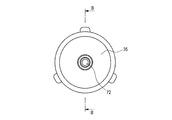
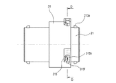
図1〜図10は本発明に係る回転式コネクタの一実施形態を示したもので、図1は本発明に係る回転式コネクタの一実施形態の組立状態の斜視図、図2は図1のA矢視図、図3は図2のB−B線に沿う断面図、図4は本発明の一実施形態の回転式コネクタの分解斜視図、図5は本発明の一実施形態の第1コネクタハウジングと第2コネクタハウジングとの対峙状態の斜視図、図6は本発明の一実施形態の第1コネクタハウジングと第2コネクタハウジングとの対峙状態の平面図、図7は本発明の一実施形態において、コネクタハウジング相互が軸方向に嵌合して、第2ハウジング本体の軸方向溝の終端に連結用ピンが到達した状態における外観図、図8は図7のD−D線に沿う断面図、図9は本発明の一実施形態において、コネクタハウジング相互の結合がロックされた状態の外観図、図10は図9のE−E線に沿う断面図である。 1 to 10 show an embodiment of a rotary connector according to the present invention, FIG. 1 is a perspective view of an assembled state of an embodiment of the rotary connector according to the present invention, and FIG. FIG. 3 is a cross-sectional view taken along line BB in FIG. 2, FIG. 4 is an exploded perspective view of a rotary connector according to one embodiment of the present invention, and FIG. 5 is a first view according to one embodiment of the present invention. FIG. 6 is a plan view of the first connector housing and the second connector housing according to one embodiment of the present invention, and FIG. 7 is one embodiment of the present invention. FIG. 8 is a cross-sectional view taken along line D-D in FIG. 7, in which the connector housings are fitted in the axial direction and the connecting pin reaches the end of the axial groove of the second housing body. FIG. 9 shows a connector housing according to an embodiment of the present invention. Appearance of the state where the mutual coupling is locked, and FIG. 10 is a sectional view taken along line E-E in FIG.
この一実施形態の回転式コネクタ10は、図1〜図5に示すように、第1コネクタハウジング20と、この第1コネクタハウジング20に嵌合接続される第2コネクタハウジング30と、を備えている。
As shown in FIGS. 1 to 5, the
第1コネクタハウジング20は、図3及び図4に示すように、第1端子金具50を収容する略筒状の第1ハウジング本体21と、該第1ハウジング本体21の先端(図3では、左端)側の内周に嵌合装着されるフロントホルダー22と、第1ハウジング本体21の先端側の外周に嵌合装着される環状のパッキン23と、第1ハウジング本体21の基端(図3では右端)側の内周に嵌合装着される第1ゴム栓24と、第1ハウジング本体21の基端を覆うリアホルダー25と、を備えている。
As shown in FIGS. 3 and 4, the
第1ハウジング本体21に収容される第1端子金具50は、先端を相手の端子金具の先端に突き当てることで相手の端子金具に導通接続される突き当てタイプの端子金具である。この第1端子金具50は、金属板のプレス成形品で、図3に示すように、当該第1端子金具50の中心軸上に延在する第1端子本体51と、この第1端子本体51の先端に装備された環状の第1環状部52と、この第1環状部52の外周の複数箇所に装備された複数の接触用ばね片53と、を備えている。
The first terminal fitting 50 accommodated in the
第1端子本体51の基端には、電線加締め片51aが装備されていて、電線71が第1端子金具50の中心軸と略同軸に圧着接続される。第1端子本体51の先端に形成された第1環状部52は、第1端子金具50の中心軸と同心の環状に形成されている。第1環状部52の外周に装備される接触用ばね片53は、第1環状部52の外周に沿って周方向に延出した弾性片に接点用突部を突出形成したものである。接触用ばね片53の接点用突部は、第1環状部52の先端よりも相手端子側に突出した状態に装備されている。
An electric
第1ハウジング本体21は、図3に示すように、内周にフロントホルダー22が嵌合する先端側円筒部211と、該先端側円筒部211の後端に連なると共に先端側円筒部211よりも外径が大きな円筒状の胴部212と、この胴部212の後端に連なると共に胴部212よりも外径が小さな円筒状の基端円筒部213と、を備えている。
As shown in FIG. 3, the first housing
先端側円筒部211及び胴部212及び基端円筒部213は、いずれも、外周の横断面形状が円形である。また、先端側円筒部211及び胴部212及び基端円筒部213は、同心の筒状である。また、胴部212は、外観的には、先端側円筒部211の基端側に鍔状に張り出している。
As for the front end side
先端側円筒部211の前端面には、図5に示すように、第1端子金具50の先端の外周に係合して第1端子金具50を回り止めする切欠211aが設けられている。
As shown in FIG. 5, the front end surface of the distal end side
本実施形態の第1ハウジング本体21の場合、胴部212の外周の周方向に離間した3箇所に、連結用ピン214が設けられている。3箇所の連結用ピン214は、円柱状で、胴部212の径方向の外方に向かって突出して設けられている。また、連結用ピン214が装備される3箇所は、胴部212の外周を3等分する位置である。
In the case of the
第1ハウジング本体21の基端円筒部213の外周には、図3に示すように、リアホルダー25を係止するための係止突起213aが突設されている。係止突起213aは、基端円筒部213の外周の2箇所に設けられている。
As shown in FIG. 3, a locking
フロントホルダー22は、図3に示すように、先端側円筒部211の前端側の内周に嵌合して、第1端子金具50の軸方向の位置を決定する。第1端子金具50は、先端面が先端側円筒部211の先端に露出するように、フロントホルダー22を介して、第1ハウジング本体21の中心軸C1上に固定される。
As shown in FIG. 3, the
パッキン23は、先端側円筒部211の外周に嵌合する。このパッキン23は、外周が後述する第2コネクタハウジング30における第2ハウジング本体の円筒部に密着して、第1ハウジング本体21と第2ハウジング本体31との嵌合部を水密に封止する。
The packing 23 is fitted to the outer periphery of the distal end side
第1ゴム栓24は、図3に示すように、第1ハウジング本体21の基端円筒部213の内周に嵌合装着される。基端円筒部213の第1ゴム栓24が装着される部位は、先端側円筒部211側の内径よりも拡径することで、第1ゴム栓24の外周縁を当接する段差部213bが形成されている。本実施形態の第1ゴム栓24は、第1ハウジング本体21の基端側から外部に導出する電線71の外周と第1ハウジング本体21の基端側の内周部との間を、水密に封止する。
As shown in FIG. 3, the
リアホルダー25は、図4に示すように、基端円筒部213の開口を覆う円盤部251と、この円盤部251の外周から延出して基端円筒部213の外周に嵌合する円筒部252と、を備えている。円盤部251の中心には、電線71を挿通させる電線挿通孔253が装備されている。円筒部252には、基端円筒部213上の係止突起213aと係合する係合孔254が形成されている。円筒部252は、係合孔254の両側に、スリット255を備えている。このスリット255は、係合孔254を有した部位を弾性変形し易くしている。基端円筒部213に取り付けられたリアホルダー25は、基端円筒部213の内周に装着された第1ゴム栓24を段差部213bに押しつけて、第1ゴム栓24を固定する。
As shown in FIG. 4, the
第2コネクタハウジング30は、図3及び図4に示すように、第2端子金具60を収容する略円筒状の第2ハウジング本体31と、該第2ハウジング本体31の先端(図3では右端)側の内周に嵌合装着されるフロントホルダー32と、第2ハウジング本体31の基端(図3では左端)側の内周に嵌合装着される第2ゴム栓34と、第2ハウジング本体31の基端を覆うリアホルダー35と、を備えている。
As shown in FIGS. 3 and 4, the
第2ハウジング本体31に収容される第2端子金具60は、先端を第1端子金具50の先端に突き当てることで第1端子金具50に導通接続される突き当てタイプの端子金具である。この第2端子金具60は、金属板のプレス成形品で、図3に示すように、当該第2端子金具60の中心軸上に延在する第2端子本体61と、この第2端子本体61の先端に装備された環状の第2環状部62と、この第2環状部62の外周の複数箇所に装備された複数の接触面63と、を備えている。
The second terminal fitting 60 housed in the
第2端子本体61の基端には、電線加締め片61aが装備されていて、電線72が第2端子金具60の中心軸と略同軸に圧着接続される。第2端子本体61の先端に形成された第2環状部62は、第2端子金具60の中心軸と同心の環状に形成されている。第2環状部62の外周に装備される接触面63は、第1端子金具50における複数の接点用突部と同じ間隔で、第2環状部62の外周から当該第2環状部62の径方向外方に向かって突設されている。また、本実施形態の第2端子金具60の場合、隣接する接触面63間は、接点用突部が没入可能な接点逃がし部64(図4参照)になっている。
An electric
第2ハウジング本体31は、図3に示すように、第1コネクタハウジング20の胴部212が嵌合する円筒部312と、該円筒部312の後端に連なると共に内径が胴部212の外径よりも小さく設定された中間円筒部313と、該中間円筒部313の後端に連なると共に第2端子金具60の収容部となる基端円筒部314と、を備えている。
As shown in FIG. 3, the
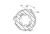
円筒部312は、第2ハウジング本体31の先端に位置している。この円筒部312には、胴部212上の連結用ピン214の装備位置に対応する3箇所に、軸方向溝315aと、周方向溝315bと、ロック用ばね片316と、が装備されている。
軸方向溝315aが装備される円筒部312上の3箇所は、円筒部312の外周を3等分する位置である。
The
Three locations on the
軸方向溝315aは、図3及び図8に示すように、円筒部312の開口端から該円筒部312の中心軸O3(図6参照)の方向に沿って延在するように、円筒部312に切欠形成されている。この軸方向溝315aは、図5及び図6に矢印X1で示すように、円筒部312の中心軸O3の方向に沿って胴部212を円筒部312に嵌合させたときに、胴部212上の連結用ピン214が進入する。この軸方向溝315aの溝幅は、連結用ピン214がスムーズに移動できるように、連結用ピン214の外径よりも僅かに大きく設定されている。
As shown in FIGS. 3 and 8, the
なお、上記の円筒部312の中心軸O3は、図3に示す第2ハウジング本体31の中心軸C2に一致する。
The central axis O3 of the
周方向溝315bは、図6及び図8に示すように、軸方向溝315aの終端から円筒部312の周方向の一側(図6では下側であり、図8では反時計方向側)に周方向に沿って所定の長さに延設されている。この周方向溝315bは、円筒部312と胴部212とを相対回転させたときに、連結用ピン214が移動する溝である。この周方向溝315bの溝幅は、連結用ピン214がスムーズに移動できるように、連結用ピン214の外径よりも僅かに大きく設定されている。なお、周方向溝315bの終端315f(図5参照)は、移動した連結用ピン214が終端の円弧面に密着するように、溝幅が修正されている。
As shown in FIGS. 6 and 8, the
本実施形態の場合、図5に示すように、軸方向溝315aの径方向の外側に、連結壁315cが設けられている。この連結壁315cは、軸方向溝315aの上方を跨いで周方向溝315bの両側の壁部と繋がっていて、周方向溝315bの周囲を補強している。
In the case of this embodiment, as shown in FIG. 5, a connecting
ロック用ばね片(本発明におけるロック部)316は、図5に示すように、上記の周方向溝315bに沿って延在するように円筒部312に一体形成されたばね片316aと、周方向溝315b内に突出するようにばね片316aに一体形成された係止突部316bとを備える。本実施形態の場合、ばね片316aは、略く字状に折れ曲がった板ばね状であり、く字状の折れ曲がり部が、係止突部316bとして機能する。
As shown in FIG. 5, the locking spring piece (the locking portion in the present invention) 316 includes a
ロック用ばね片316は、連結用ピン214が周方向溝315bの終端315fに到達したときに、図9に示すように、係止突部316bが周方向溝315bの始端側から連結用ピン214に弾性接触して、連結用ピン214の戻り方向(図9の矢印R1方向)への移動を規制する。
As shown in FIG. 9, when the connecting
また、本実施形態のロック用ばね片316は、図9に示すように、周方向溝315bの終端315fに位置している連結用ピン214から周方向溝315bの始端側に向かう所定以上の押圧力F1を係止突部316bに受けた場合には、係止突部316bが周方向溝315bから退出して、連結用ピン214の周方向溝315bの始端側への移動を許容する。即ち、本実施形態の場合、第2ハウジング本体31と第1ハウジング本体21との結合がロックされている状態で、連結用ピン214が周方向溝315bの始端側に戻るように、第2ハウジング本体31又は第1ハウジング本体21に回転操作力を作用させると、回転操作力が一定以上に達したときに、ロック用ばね片316が周方向溝315bの外側に退避して、連結用ピン214が周方向溝315bの始端側に移動可能になる。
Further, as shown in FIG. 9, the locking
第2ハウジング本体31における中間円筒部313は、図3に示したように、第1ハウジング本体21の先端側円筒部211を収容する筒部である。該中間円筒部313は、先端側円筒部211との間にパッキン23を挟持するように、内径が設定されている。中間円筒部313と先端側円筒部211との間に挟持されるパッキン23は、内周が先端側円筒部211に密着すると共に外周が中間円筒部313に密着していて、第1ハウジング本体21と第2ハウジング本体31との間の嵌合部を水密に封止している。
As shown in FIG. 3, the intermediate
第2ハウジング本体31における基端円筒部314は、図3に示すように、内径が中間円筒部313の内径よりも小さく設定されている。この基端円筒部314は、第2端子金具60を収容するだけでなく、第2端子金具60の軸方向の位置を規制するフロントホルダー32が嵌合装着される。基端円筒部314は、フロントホルダー32を介して、第2端子金具60を第2ハウジング本体31の中心軸C2上に固定支持している。
As shown in FIG. 3, the base end
基端円筒部314の基端の外周には、図3に示すように、リアホルダー35を係止するための係止突起314aが突設されている。係止突起314aは、基端円筒部314の外周の2箇所に設けられている。
As shown in FIG. 3, a locking
基端円筒部314の基端の内周には、図3に示すように、第2ゴム栓34が嵌合装着されている。基端円筒部314の第2ゴム栓34が装着される部位は、フロントホルダー32側の内径よりも拡径することで、第2ゴム栓34の外周縁を当接する段差部314bが形成されている。
As shown in FIG. 3, a
本実施形態の第2ゴム栓34は、第2ハウジング本体31の基端側から外部に導出する電線72の外周と第2ハウジング本体31の基端側の内周部との間を、水密に封止する。
The
リアホルダー35は、図4に示すように、基端円筒部314の開口を覆う円盤部351と、この円盤部351の外周から延出して基端円筒部314の外周に嵌合する円筒部352と、を備えている。円盤部351の中心には、電線72を挿通させる電線挿通孔353が装備されている。円筒部352には、基端円筒部314上の係止突起314aと係合する係合孔354が形成されている。円筒部352は、係合孔354の両側に、スリット355を備えている。このスリット355は、係合孔354を有した部位を弾性変形し易くしている。基端円筒部314に取り付けられたリアホルダー35は、図3に示すように、基端円筒部314の内周に装着された第2ゴム栓34を段差部313bに押しつけて、第2ゴム栓34を固定する。
As shown in FIG. 4, the
次に、以上に説明した一実施形態の回転式コネクタ10における第1コネクタハウジング20と第2コネクタハウジング30とを嵌合接続させる手順、及び作用・効果を、図5〜図10に基づいて説明する。
Next, a procedure for fitting and connecting the
まず、第1コネクタハウジング20と第2コネクタハウジング30とは、図5及び図6に示すように、第2ハウジング本体31の円筒部312の複数の軸方向溝315aの位置に第1ハウジング本体21の胴部212の複数の連結用ピン214の位置を整合させた対峙状態にする。次いで、図6に矢印X1で示すように、これらの第2ハウジング本体31と第1ハウジング本体21とを、第2ハウジング本体31の円筒部312の中心軸O3の方向に沿って突き合わせて、図7及び図8に示した嵌合状態を得る。図7及び図8に示した嵌合状態は、各連結用ピン214を対応する軸方向溝315aの終端に到達させた状態である。
First, as shown in FIGS. 5 and 6, the
なお、図示はしていないが、ハウジング本体21,31相互が図7及び図8に示した嵌合状態のとき、それぞれのハウジング本体21,31に固定支持されている第1端子金具50と第2端子金具60とは、第1端子金具50に装備された接触用ばね片53が第2端子金具60に装備された接点逃がし部64に没入した状態で、それぞれの先端部同士が突き合わさっている。
Although not shown, when the housing
次いで、これらのハウジング本体21,31相互を相対回転させて、第1ハウジング本体21上の各連結用ピン214を第2ハウジング本体31上の各周方向溝315bに進入させると、これらのハウジング本体21,31相互の軸方向の移動が規制され、コネクタハウジング20,30相互が結合状態になる。
Next, when the housing
更に、各連結用ピン214が各周方向溝315bの終端315fに到達するまで、ハウジング本体21,31相互を相対回転させると、図9及び図10に示すように、ロック用ばね片316の係止突部316bが、周方向溝315bの始端側から連結用ピン214に弾性接触して、連結用ピン214の戻り方向への移動を規制するため、コネクタハウジング20,30相互の結合状態がロックされる。
Further, when the housing
なお、図示はしていないが、ハウジング本体21,31相互が図9及び図10に示したロック状態のとき、それぞれのハウジング本体21,31に固定支持されている第1端子金具50と第2端子金具60とは、第1端子金具50に装備された接触用ばね片53が第2端子金具60に装備された接触面63に乗り上げて、第1端子金具50と第2端子金具60とが導通接続された状態になる。
Although not shown, when the housing
即ち、本実施形態の回転式コネクタ10では、第2コネクタハウジング30の円筒部312に一体形成されたロック用ばね片316によって、コネクタハウジング相互の結合状態がロックされる。言い換えると、本実施形態の回転式コネクタ10では、ロック機構にはコネクタハウジング20,30と別体の部品を使用していないため、ロック機構にコネクタハウジングと別体の複数の部品を使用していた従来の回転式コネクタと比較すると、構成部品の削減によりコストの低減を図ることができる。
That is, in the
また、本実施形態の回転式コネクタ10では、図9及び図10に示したようにハウジング本体21,31間の結合状態がロックされている状態で、ロック時とは逆方向にハウジング本体間に回転操作力を付与して、連結用ピン214からロック用ばね片316の係止突部316bに、周方向溝315bの始端側に向かう所定以上の押圧力を作用させると、係止突部316bが周方向溝315bから退出して、ロック解除状態となり、連結用ピン214が周方向溝315bの始端側へ移動することが可能になる。
Further, in the
従って、連結用ピン214が周方向溝315bの始端(即ち、軸方向溝315aの終端)に到達するまで、ハウジング本体相互を回転操作した後、ハウジング本体相互を軸方向に引き離すことで、コネクタハウジング20,30相互を離脱状態にすることができる。
Therefore, after rotating the housing bodies until the connecting
即ち、本実施形態の回転式コネクタ10では、工具を使わずに、軸方向の移動操作と周方向への回転操作だけで、コネクタハウジング20,30相互を簡単に着脱することができる。
That is, in the
また、本実施形態の回転式コネクタ10では、ロック機構となるロック用ばね片316は、第2コネクタハウジング30の円筒部312上で周方向に沿って延設されており、コネクタハウジング30の軸方向にはそれほどスペースを占有しない。そのため、ロック用ばね片316を有する第2コネクタハウジング30の軸方向の長さを短縮させて、コネクタ全長の短縮を図ることができる。従って、十分な設置スペースの確保が難しい車両への搭載性を向上させることもできる。
Further, in the
また、本実施形態の回転式コネクタ10では、コネクタハウジング20,30相互の結合状態がロックされている状態では、図3に示したように、第1コネクタハウジング20の基端に装備された第1ゴム栓24とコネクタハウジング相互の嵌合部に装備されたパッキン23と第2コネクタハウジング30の基端に装備された第2ゴム栓34とによって、コネクタ内部が防水状態に保たれる。従って、車両等において防水性が要求されるエンジンルーム等での配線接続にも、良好に使用することができる。
Further, in the
なお、本発明は、上述した実施形態に限定されるものではなく、適宜、変形、改良、等が可能である。その他、上述した実施形態における各構成要素の材質、形状、寸法、数、配置箇所、等は本発明を達成できるものであれば任意であり、限定されない。 In addition, this invention is not limited to embodiment mentioned above, A deformation | transformation, improvement, etc. are possible suitably. In addition, the material, shape, dimensions, number, arrangement location, and the like of each component in the above-described embodiment are arbitrary and are not limited as long as the present invention can be achieved.
例えば、突き当てタイプの端子金具である第1端子金具及び第2端子金具は、図7及び図8に示したコネクタハウジング相互の突き当て完了時に、それぞれの端子金具の先端面同士が突き合わさって、導通接続状態になる構造にすることもできる。 For example, the first terminal fitting and the second terminal fitting, which are abutting type terminal fittings, are brought into contact with each other at the end surfaces of the respective terminal fittings when the abutting of the connector housings shown in FIGS. 7 and 8 is completed. In addition, a structure that is in a conductive connection state can also be used.
また、上記実施形態は、第1ハウジング本体21に連結用ピン214が設けられ、第2ハウジング本体31に軸方向溝315a、周方向溝315b及びロック用ばね片316が設けられた構成であるが、第2ハウジング本体31に連結用ピン214が設けられ、第1ハウジング本体21に軸方向溝315a、周方向溝315b及びロック用ばね片316が設けられた構成であってもよい。この場合、第2ハウジング本体31に設けられる連結用ピン214は、径方向内方に向けて突出するように設けられる。
In the above embodiment, the
また、上記実施形態は、連結用ピン214及びロック用ばね片316が各ハウジング本体21,31に複数設けられた構成であるが、連結用ピン214及びロック用ばね片316は、各ハウジング本体21,31に1つずつ設けられてもよい。
In the above embodiment, a plurality of connecting
また、ロック部316は、上記実施形態のようにばね片316aと係止突部316bとで構成されなくてもよく、肉抜き部が省略されてばね片316aが省略された、周方向溝315b内に張り出した係止突部316bだけの構成であってもよい。この場合、連結用ピン214は、係止突部316bにより狭められた周方向溝315b内の部分を圧接状態で通過することができる。
Further, the
また、各コネクタハウジングに収容される端子金具は、突き当てタイプに限らない。例えば、一方の端子金具は一方のハウジングに装備される円柱部の外周面上に接点部を配置する構造とし、他方の端子金具は、前記円柱部が嵌合する他方のハウジングの円筒部の内周面上に接点部を配置する構造とし、ハウジング相互の回転操作によって、それぞれの接点部が接触する構造とすることも可能である。 Moreover, the terminal metal fitting accommodated in each connector housing is not restricted to a butting type. For example, one terminal fitting has a structure in which a contact portion is arranged on the outer peripheral surface of a cylindrical portion provided in one housing, and the other terminal fitting has an inner portion of a cylindrical portion of the other housing to which the cylindrical portion is fitted. It is also possible to have a structure in which contact portions are arranged on the peripheral surface, and a structure in which the respective contact portions come into contact with each other by a rotation operation between the housings.
ここで、上述した本発明に係る回転嵌合式コネクタの実施形態の特徴をそれぞれ以下[1]〜[3]に簡潔に纏めて列記する。 Here, the features of the embodiment of the rotary fitting connector according to the present invention described above are briefly summarized and listed in the following [1] to [3], respectively.
[1] 外周の横断面形状が円形であり第1端子金具(50)を収容した第1ハウジング本体(21)と、前記第1ハウジング本体(21)に径方向に沿って突出して設けられた連結用ピン(214)と、を備えた第1コネクタハウジング(20)と、
外周の横断面形状が円形であり前記第1ハウジング本体(21)が嵌合すると共に前記第1端子金具(50)に接続する第2端子金具(60)を収容した第2ハウジング本体(31)と、前記第2ハウジング本体(31)の前記第1コネクタハウジング(20)側の端部から前記第2ハウジング本体(31)の中心軸方向に沿って延在するように切欠形成されて前記第2ハウジング本体(31)の中心軸方向に沿って前記第1ハウジング本体(21)を前記第2ハウジング本体(31)に嵌合させたときに前記連結用ピン(214)が進入する軸方向溝(315a)と、前記軸方向溝(315a)の終端から前記第2ハウジング本体(31)の周方向の一側に前記周方向に沿って延設されて前記第2ハウジング本体(31)と前記第1ハウジング本体(21)とを相対回転させたときに前記連結用ピン(214)が移動する周方向溝(315b)と、前記周方向溝(315b)内に突出して設けられ前記連結用ピン(214)が前記周方向溝(315b)の終端に到達したときに前記周方向溝(315b)の始端側から前記連結用ピン(214)に接触して前記連結用ピン(214)の戻り方向への移動を規制するロック部(316)と、を備えた第2コネクタハウジング(30)と、
を備え、
前記ロック部(316)は、前記周方向溝(315b)の終端に位置している前記連結用ピン(214)から前記周方向溝(315b)の始端側に向かう所定以上の押圧力を受けた場合には、前記連結用ピン(214)の前記周方向溝(315b)の始端側への移動を許容することを特徴とする回転式コネクタ(10)。
[1] A first housing body (21) that has a circular outer cross-sectional shape and accommodates the first terminal fitting (50), and is provided to protrude in the radial direction on the first housing body (21). A first connector housing (20) comprising a coupling pin (214);
A second housing body (31) having a circular outer cross-sectional shape and accommodating a second terminal fitting (60) connected to the first terminal fitting (50) while fitting the first housing body (21). And the second housing body (31) is notched so as to extend from the end on the first connector housing (20) side along the central axis direction of the second housing body (31). 2 An axial groove into which the connecting pin (214) enters when the first housing body (21) is fitted to the second housing body (31) along the central axis direction of the housing body (31). (315a) extending from the terminal end of the axial groove (315a) to one side in the circumferential direction of the second housing body (31) along the circumferential direction, and the second housing body (31) and the First housing A circumferential groove (315b) in which the connecting pin (214) moves when the main body (21) is rotated relative to the main body (21), and the connecting pin (214) protruding from the circumferential groove (315b). ) Reaches the end of the circumferential groove (315b) from the start end side of the circumferential groove (315b) and contacts the connecting pin (214) in the return direction of the connecting pin (214). A second connector housing (30) comprising a lock portion (316) for restricting movement;
With
The lock portion (316) receives a pressing force of a predetermined level or more toward the start end side of the circumferential groove (315b) from the connecting pin (214) located at the end of the circumferential groove (315b). In this case, the rotary connector (10) is characterized in that the connecting pin (214) is allowed to move toward the start end of the circumferential groove (315b).
[2] 前記第1ハウジング本体(21)の基端側から外部に導出する電線(71)の外周と前記第1ハウジング本体(21)の基端側の内周部との間を水密に封止する第1ゴム栓(24)と、
前記第2ハウジング本体(31)の基端側から外部に導出する電線(72)の外周と前記第2ハウジング本体(31)の基端側の内周部との間を水密に封止する第2ゴム栓(34)と、
前記第1ハウジング本体(21)と前記第2ハウジング本体(31)との嵌合部に装備されて前記第1ハウジング本体(21)と前記第2ハウジング本体(31)との嵌合部を水密に封止するパッキン(23)と、
を備えたことを特徴とする上記[1]に記載の回転式コネクタ(10)。
[2] Watertight sealing between the outer periphery of the electric wire (71) led out from the base end side of the first housing body (21) and the inner peripheral portion of the base end side of the first housing body (21). A first rubber stopper (24) to be stopped;
A watertight seal is formed between the outer periphery of the electric wire (72) led out from the proximal end side of the second housing body (31) and the inner circumferential portion of the proximal end side of the second housing body (31). 2 rubber stoppers (34),
The fitting portion between the first housing body (21) and the second housing body (31) is water-tightly mounted on the fitting portion between the first housing body (21) and the second housing body (31). Packing (23) for sealing to
The rotary connector (10) according to the above [1], comprising:
[3] 外周の横断面形状が円形の胴部(212)を備えると共に第1端子金具(50)を収容した第1ハウジング本体(21)と、前記胴部(212)の外周の周方向に離間した複数箇所に前記胴部(212)の径方向の外方に向かって突出して設けられた複数の連結用ピン(214)と、を備えた第1コネクタハウジング(20)と、
前記胴部(212)が嵌合する円筒部(312)を備えると共に前記第1端子金具(50)に接続する第2端子金具(60)を収容した第2ハウジング本体(31)と、前記円筒部(312)の開口端から前記円筒部(312)の中心軸方向に沿って延在するように切欠形成されて前記円筒部(312)の中心軸方向に沿って前記胴部(212)を前記円筒部(312)に嵌合させたときに複数の前記連結用ピン(214)が進入する複数の軸方向溝(315a)と、前記軸方向溝(315a)の終端から前記円筒部(312)の周方向の一側に前記周方向に沿って延設されて前記円筒部(312)と前記胴部(212)とを相対回転させたときに前記連結用ピン(214)が移動する複数の周方向溝(315b)と、該周方向溝(315b)に沿って延在するように前記円筒部(312)に一体形成されたばね片(316a)と前記周方向溝(315b)内に突出するように前記ばね片(316a)に一体形成された係止突部(316b)とを備えて前記連結用ピン(214)が前記周方向溝(315b)の終端に到達したときに前記係止突部(316b)が前記周方向溝(315b)の始端側から前記連結用ピン(214)に弾性接触して前記連結用ピン(214)の戻り方向への移動を規制するロック用ばね片(316)と、を備えた第2コネクタハウジング(30)と、
を備え、
前記ロック用ばね片(316)は、前記周方向溝(315b)の終端に位置している前記連結用ピン(214)から前記周方向溝(315b)の始端側に向かう所定以上の押圧力を前記係止突部(316b)に受けた場合には、前記係止突部(316b)が前記周方向溝(315b)から退出して、前記連結用ピン(214)の前記周方向溝(315b)の始端側への移動を許容することを特徴とする回転式コネクタ(10)。
[3] A first housing body (21) provided with a body (212) having a circular outer cross-sectional shape and containing a first terminal fitting (50), and a circumferential direction of the outer periphery of the body (212) A first connector housing (20) comprising a plurality of connecting pins (214) provided projecting outward in the radial direction of the body (212) at a plurality of spaced locations;
A second housing body (31) having a cylindrical portion (312) to which the body portion (212) is fitted and accommodating a second terminal fitting (60) connected to the first terminal fitting (50); A notch is formed so as to extend from the opening end of the portion (312) along the central axis direction of the cylindrical portion (312), and the trunk portion (212) is formed along the central axis direction of the cylindrical portion (312). A plurality of axial grooves (315a) into which the plurality of connecting pins (214) enter when fitted into the cylindrical part (312), and the cylindrical part (312) from the end of the axial groove (315a) ) Extending along the circumferential direction on one side in the circumferential direction, and the coupling pin (214) moves when the cylindrical portion (312) and the body portion (212) are relatively rotated. Circumferential groove (315b) and circumferential groove (315b) A spring piece (316a) integrally formed on the cylindrical portion (312) so as to extend along the groove and a latch integrally formed on the spring piece (316a) so as to protrude into the circumferential groove (315b) Provided with a protrusion (316b), and when the connecting pin (214) reaches the end of the circumferential groove (315b), the locking protrusion (316b) is at the start side of the circumferential groove (315b). A second connector housing (30) provided with a locking spring piece (316) for restricting movement of the connecting pin (214) in the return direction by elastic contact with the connecting pin (214) from
With
The locking spring piece (316) applies a pressing force of a predetermined value or more toward the starting end side of the circumferential groove (315b) from the connecting pin (214) located at the end of the circumferential groove (315b). When the locking projection (316b) receives the locking projection (316b), the locking projection (316b) retracts from the circumferential groove (315b) and the circumferential groove (315b) of the connecting pin (214). ) Is allowed to move toward the start end side of the rotary connector (10).
10 回転式コネクタ
20 第1コネクタハウジング
21 第1ハウジング本体
23 パッキン
24 第1ゴム栓
30 第2コネクタハウジング
31 第2ハウジング本体
34 第2ゴム栓
50 第1端子金具
60 第2端子金具
212 胴部
214 連結用ピン
312 円筒部
315a 軸方向溝
315b 周方向溝
316 ロック用ばね片
316a ばね片
316b 係止突部
DESCRIPTION OF
Claims (2)
外周の横断面形状が円形であり前記第1ハウジング本体が嵌合すると共に前記第1端子金具に接続する第2端子金具を収容した第2ハウジング本体と、前記第2ハウジング本体の前記第1コネクタハウジング側の端部から前記第2ハウジング本体の中心軸方向に沿って延在するように切欠形成されて前記第2ハウジング本体の中心軸方向に沿って前記第1ハウジング本体を前記第2ハウジング本体に嵌合させたときに前記連結用ピンが進入する軸方向溝と、前記軸方向溝の終端から前記第2ハウジング本体の周方向の一側に前記周方向に沿って延設されて前記第2ハウジング本体と前記第1ハウジング本体とを相対回転させたときに前記連結用ピンが移動する周方向溝と、前記周方向溝内に突出して設けられたロック部であって、前記周方向溝の始端と終端との間の範囲の一部に位置している前記連結用ピンに接触することにより前記周方向溝から退出すると共に当該ロック部と前記第2ハウジング本体との間の間隙に入るように弾性変形し、前記連結用ピンが前記周方向溝の終端に到達したときに前記周方向溝の始端側から前記連結用ピンに接触して前記連結用ピンの戻り方向への移動を規制する前記ロック部と、前記軸方向溝の径方向の外側に設けられると共に前記軸方向溝の上方を跨いで前記周方向溝の両側の壁部と繋がっている連結壁と、を備えた第2コネクタハウジングと、
を備え、
前記ロック部は、前記周方向溝の終端に位置している前記連結用ピンから前記周方向溝の始端側に向かう所定以上の押圧力を受けた場合には、前記連結用ピンの前記周方向溝の始端側への移動を許容することを特徴とする回転式コネクタ。 A first connector housing comprising: a first housing body having a circular outer cross-sectional shape and accommodating a first terminal fitting; and a connecting pin provided to project from the first housing body along a radial direction; ,
A second housing body that has a circular outer cross-sectional shape and is fitted with the first housing body and accommodates a second terminal fitting connected to the first terminal fitting, and the first connector of the second housing body A notch is formed so as to extend from the end on the housing side along the central axis direction of the second housing body, and the first housing body is moved along the central axis direction of the second housing body. An axial groove into which the connecting pin enters when fitted to the second housing body, and extends from the terminal end of the axial groove along one circumferential direction of the second housing body along the circumferential direction. 2 a circumferential groove in which the connecting pin moves when the housing body and the first housing body are rotated relative to each other, and a lock portion protruding from the circumferential groove, the circumferential direction By contacting the connecting pin located in a part of the range between the starting end and the terminal end of the housing, and withdrawing from the circumferential groove and entering the gap between the lock portion and the second housing body When the connecting pin reaches the end of the circumferential groove, the connecting pin comes into contact with the connecting pin from the start end side of the circumferential groove to restrict the return of the connecting pin in the return direction. And a connecting wall that is provided on the radially outer side of the axial groove and is connected to the wall portions on both sides of the circumferential groove across the upper side of the axial groove . A connector housing;
With
When the locking portion receives a pressing force of a predetermined level or more toward the start end side of the circumferential groove from the coupling pin located at the end of the circumferential groove, the circumferential direction of the coupling pin A rotary connector characterized by allowing movement to the start end side of a groove.
前記第2ハウジング本体の基端側から外部に導出する電線の外周と前記第2ハウジング本体の基端側の内周部との間を水密に封止する第2ゴム栓と、
前記第1ハウジング本体と前記第2ハウジング本体との嵌合部に装備されて前記第1ハウジング本体と前記第2ハウジング本体との嵌合部を水密に封止するパッキンと、
を備えたことを特徴とする請求項1に記載の回転式コネクタ。 A first rubber plug for watertightly sealing between the outer periphery of the electric wire led out from the base end side of the first housing body and the inner peripheral part of the base end side of the first housing body;
A second rubber plug for watertightly sealing between the outer periphery of the electric wire led out from the base end side of the second housing body and the inner peripheral portion of the base end side of the second housing body;
A packing provided in a fitting portion between the first housing body and the second housing body to seal the fitting portion between the first housing body and the second housing body in a watertight manner;
The rotary connector according to claim 1, further comprising:
Priority Applications (4)
| Application Number | Priority Date | Filing Date | Title |
|---|---|---|---|
| JP2013139098A JP6106544B2 (en) | 2013-07-02 | 2013-07-02 | Rotary connector |
| DE112014003125.9T DE112014003125B4 (en) | 2013-07-02 | 2014-06-27 | rotary connector |
| US14/896,033 US9531112B2 (en) | 2013-07-02 | 2014-06-27 | Rotary connector |
| PCT/JP2014/067259 WO2015002107A1 (en) | 2013-07-02 | 2014-06-27 | Rotary connector |
Applications Claiming Priority (1)
| Application Number | Priority Date | Filing Date | Title |
|---|---|---|---|
| JP2013139098A JP6106544B2 (en) | 2013-07-02 | 2013-07-02 | Rotary connector |
Publications (3)
| Publication Number | Publication Date |
|---|---|
| JP2015011962A JP2015011962A (en) | 2015-01-19 |
| JP2015011962A5 JP2015011962A5 (en) | 2016-10-13 |
| JP6106544B2 true JP6106544B2 (en) | 2017-04-05 |
Family
ID=52143685
Family Applications (1)
| Application Number | Title | Priority Date | Filing Date |
|---|---|---|---|
| JP2013139098A Active JP6106544B2 (en) | 2013-07-02 | 2013-07-02 | Rotary connector |
Country Status (4)
| Country | Link |
|---|---|
| US (1) | US9531112B2 (en) |
| JP (1) | JP6106544B2 (en) |
| DE (1) | DE112014003125B4 (en) |
| WO (1) | WO2015002107A1 (en) |
Families Citing this family (20)
| Publication number | Priority date | Publication date | Assignee | Title |
|---|---|---|---|---|
| JP6034755B2 (en) * | 2013-06-14 | 2016-11-30 | 矢崎総業株式会社 | Terminal structure |
| JP6268606B2 (en) * | 2014-11-10 | 2018-01-31 | 株式会社オートネットワーク技術研究所 | Terminal bracket |
| JP5922271B1 (en) | 2015-02-12 | 2016-05-24 | 住友電装株式会社 | Wire insertion member |
| JP6422386B2 (en) * | 2015-03-31 | 2018-11-14 | ニッタ株式会社 | Connector device |
| DE102015120921B4 (en) * | 2015-12-02 | 2017-10-19 | Kathrein Werke Kg | Connector and plug connector assembly |
| US10337533B2 (en) * | 2016-02-02 | 2019-07-02 | Yazaki Corporation | Connecting structure of electromagnetic valve and hydraulic pressure control device |
| US9595789B1 (en) * | 2016-02-10 | 2017-03-14 | I.D. Systems, Inc. | Connector locking mechanism having a sliding connection retention component |
| JP6195137B1 (en) * | 2016-04-11 | 2017-09-13 | 株式会社オートネットワーク技術研究所 | connector |
| IT201600130365A1 (en) * | 2016-12-22 | 2018-06-22 | Techno Group S R L | DEVICE FOR ELECTRICAL INTERCONNECTION OF ELECTRIC CONDUCTORS |
| FR3066861B1 (en) * | 2017-05-23 | 2020-10-30 | Axon Cable Sa | COMPACT QUART-TURN CONNECTOR |
| DE102017112629B4 (en) * | 2017-06-08 | 2019-11-14 | Phoenix Contact Gmbh & Co. Kg | Connector with a locking part |
| CN107221794A (en) * | 2017-06-08 | 2017-09-29 | 北京北方长龙新材料技术有限公司 | It is a kind of can fast insert-pull attachment means |
| LU100281B1 (en) * | 2017-06-09 | 2018-12-18 | Highyag Lasertechnologie Gmbh | Holder for optical fiber connector |
| USD913955S1 (en) * | 2017-06-26 | 2021-03-23 | Marechal Electric | Connector |
| DE102017118014B3 (en) * | 2017-08-08 | 2018-07-12 | Phoenix Contact Gmbh & Co. Kg | Connector part with a locking element |
| JP6870599B2 (en) * | 2017-12-05 | 2021-05-12 | 住友電装株式会社 | Connector support |
| US10424866B1 (en) * | 2018-12-19 | 2019-09-24 | F Time Technology Industrial Co., Ltd. | Waterproof connector |
| TWI660547B (en) * | 2018-12-21 | 2019-05-21 | 飛宏科技股份有限公司 | Electrical cable device with waterproof structure |
| CN111628315B (en) * | 2019-02-27 | 2021-06-04 | 上海莫仕连接器有限公司 | Electric connector combination |
| CN111223694B (en) * | 2020-01-15 | 2022-10-11 | 萧县华企云谷中小企业服务中心有限公司 | Magnetic self-locking protection device for SOS button of train toilet |
Family Cites Families (20)
| Publication number | Priority date | Publication date | Assignee | Title |
|---|---|---|---|---|
| US3112976A (en) * | 1960-10-14 | 1963-12-03 | Nat Company Inc | Electrical connector |
| DE2136022C3 (en) | 1971-07-19 | 1979-06-13 | Siemens Ag | Multiple connector |
| US4305180A (en) * | 1979-12-14 | 1981-12-15 | International Telephone And Telegraph Corporation | Bayonet coupling nut |
| US4359256A (en) * | 1980-11-14 | 1982-11-16 | The Bendix Corporation | Electrical connector coupling member |
| JPS59170382U (en) * | 1983-04-28 | 1984-11-14 | エスエムケイ株式会社 | connector |
| US4542952A (en) | 1984-04-27 | 1985-09-24 | Allied Corporation | Electrical connector assembly having locking means |
| JPH01170966U (en) * | 1988-05-21 | 1989-12-04 | ||
| JPH0548249U (en) * | 1991-12-05 | 1993-06-25 | 日本航空電子工業株式会社 | connector |
| FR2694053B1 (en) * | 1992-07-24 | 1994-09-02 | Souriau & Cie | Bayonet type locking connection assembly. |
| JP2937225B2 (en) * | 1994-03-22 | 1999-08-23 | 矢崎総業株式会社 | Shield connector |
| JPH08293355A (en) * | 1995-04-21 | 1996-11-05 | Sumitomo Wiring Syst Ltd | Electric element connecting connector |
| JPH09147987A (en) * | 1995-11-17 | 1997-06-06 | Sumitomo Wiring Syst Ltd | Half-fitting detecting connector |
| US5685730A (en) | 1996-03-15 | 1997-11-11 | Litton Precision Products International, Inc. | Power connector set with secondary lock |
| EP0909870A1 (en) * | 1997-10-15 | 1999-04-21 | DIAMANT BOART Société Anonyme | Coupling for a force transmitting device |
| JP3053188U (en) * | 1998-04-13 | 1998-10-23 | 株式会社七星科学研究所 | Connector locking mechanism |
| JP3322210B2 (en) * | 1998-05-12 | 2002-09-09 | 住友電装株式会社 | 1 pole connector |
| IT1320298B1 (en) * | 2000-04-21 | 2003-11-26 | Menber S Spa | ADAPTER FOR THE ELECTRICAL CONNECTION BETWEEN A PLUG AND A SOCKET. |
| GB0228503D0 (en) * | 2002-12-06 | 2003-01-15 | Ten47 Ltd | Electrical power connector |
| GB2459886A (en) | 2008-05-09 | 2009-11-11 | Fusion Components Ltd | Shielded electrical connector having resiliently urging means making electrical connection between cable shield and connector |
| JP6035742B2 (en) | 2011-12-28 | 2016-11-30 | ぺんてる株式会社 | Ballpoint pen refill |
-
2013
- 2013-07-02 JP JP2013139098A patent/JP6106544B2/en active Active
-
2014
- 2014-06-27 US US14/896,033 patent/US9531112B2/en active Active
- 2014-06-27 DE DE112014003125.9T patent/DE112014003125B4/en active Active
- 2014-06-27 WO PCT/JP2014/067259 patent/WO2015002107A1/en active Application Filing
Also Published As
| Publication number | Publication date |
|---|---|
| WO2015002107A1 (en) | 2015-01-08 |
| JP2015011962A (en) | 2015-01-19 |
| US9531112B2 (en) | 2016-12-27 |
| DE112014003125B4 (en) | 2018-05-30 |
| DE112014003125T5 (en) | 2016-03-31 |
| US20160134048A1 (en) | 2016-05-12 |
Similar Documents
| Publication | Publication Date | Title |
|---|---|---|
| JP6106544B2 (en) | Rotary connector | |
| JP6031006B2 (en) | Terminal fitting connection structure and rotation fitting type connector | |
| JP6730353B2 (en) | connector | |
| JP5863179B2 (en) | Waterproof connector | |
| JP5003583B2 (en) | connector | |
| US9209561B2 (en) | Connector structure | |
| WO2018142887A1 (en) | Shield terminal | |
| JP6889696B2 (en) | Corrugated tube holder and wire harness | |
| JP2012018877A (en) | Lever-type connector | |
| WO2014175176A1 (en) | Connector | |
| KR20190004339A (en) | Push lifter | |
| JP5565946B2 (en) | connector | |
| CN116941143A (en) | Rod type connector | |
| JP5999440B2 (en) | connector | |
| JP2009266642A (en) | Connector | |
| JP6710579B2 (en) | Connector shield and connector | |
| JP5912731B2 (en) | Terminal connection structure | |
| JP5863181B2 (en) | connector | |
| JP6228148B2 (en) | Connector waterproof structure | |
| JP2010092614A (en) | Connector | |
| JP2019016472A (en) | Semi-mating prevention connector | |
| JP6040088B2 (en) | connector | |
| JP6032169B2 (en) | Connector mounting structure and connector | |
| JP2012043741A (en) | Connector | |
| JP7168419B2 (en) | Corrugated tube holder and wire harness |
Legal Events
| Date | Code | Title | Description |
|---|---|---|---|
| RD02 | Notification of acceptance of power of attorney |
Free format text: JAPANESE INTERMEDIATE CODE: A7422 Effective date: 20150122 |
|
| A621 | Written request for application examination |
Free format text: JAPANESE INTERMEDIATE CODE: A621 Effective date: 20160519 |
|
| A521 | Request for written amendment filed |
Free format text: JAPANESE INTERMEDIATE CODE: A523 Effective date: 20160824 |
|
| A131 | Notification of reasons for refusal |
Free format text: JAPANESE INTERMEDIATE CODE: A131 Effective date: 20160920 |
|
| A521 | Request for written amendment filed |
Free format text: JAPANESE INTERMEDIATE CODE: A523 Effective date: 20161021 |
|
| TRDD | Decision of grant or rejection written | ||
| A01 | Written decision to grant a patent or to grant a registration (utility model) |
Free format text: JAPANESE INTERMEDIATE CODE: A01 Effective date: 20170207 |
|
| A61 | First payment of annual fees (during grant procedure) |
Free format text: JAPANESE INTERMEDIATE CODE: A61 Effective date: 20170306 |
|
| R150 | Certificate of patent or registration of utility model |
Ref document number: 6106544 Country of ref document: JP Free format text: JAPANESE INTERMEDIATE CODE: R150 |
|
| R250 | Receipt of annual fees |
Free format text: JAPANESE INTERMEDIATE CODE: R250 |
|
| R250 | Receipt of annual fees |
Free format text: JAPANESE INTERMEDIATE CODE: R250 |
|
| R250 | Receipt of annual fees |
Free format text: JAPANESE INTERMEDIATE CODE: R250 |
|
| R250 | Receipt of annual fees |
Free format text: JAPANESE INTERMEDIATE CODE: R250 |
|
| S531 | Written request for registration of change of domicile |
Free format text: JAPANESE INTERMEDIATE CODE: R313531 |
|
| R350 | Written notification of registration of transfer |
Free format text: JAPANESE INTERMEDIATE CODE: R350 |
|
| R250 | Receipt of annual fees |
Free format text: JAPANESE INTERMEDIATE CODE: R250 |