JP2019016472A - Semi-mating prevention connector - Google Patents
Semi-mating prevention connector Download PDFInfo
- Publication number
- JP2019016472A JP2019016472A JP2017131639A JP2017131639A JP2019016472A JP 2019016472 A JP2019016472 A JP 2019016472A JP 2017131639 A JP2017131639 A JP 2017131639A JP 2017131639 A JP2017131639 A JP 2017131639A JP 2019016472 A JP2019016472 A JP 2019016472A
- Authority
- JP
- Japan
- Prior art keywords
- connector
- terminal
- male
- elastic member
- fitting
- Prior art date
- Legal status (The legal status is an assumption and is not a legal conclusion. Google has not performed a legal analysis and makes no representation as to the accuracy of the status listed.)
- Granted
Links
Images


Abstract
Description
本発明は、半嵌合防止機能を備えた半嵌合防止コネクタに関する。 The present invention relates to a half-fitting prevention connector having a half-fitting prevention function.
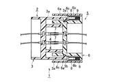
この種の半嵌合防止コネクタとして、図5と図6に示すものが知られている。この半嵌合防止コネクタ1は、図5と図6に示すように、雌ハウジング3に雌端子4を有すると共に、雌ハウジング3の外側に一対のロックアーム3a,3aを有する雌コネクタ2と、雄ハウジング6に雄端子7を有すると共に、雌コネクタ2に嵌合した際に、ロックアーム3aのロック突部3bが係止される係止凹部6aを有する雄コネクタ5と、雄ハウジング6の一対のバネ収容部6b,6b内にスライド自在に設けられ、雌コネクタ2の嵌合方向Aに沿ってスライドする一対のスライド部材8,8と、雌,雄コネクタ2,5の半嵌合時にスライド部材8を雌コネクタ2の反嵌合方向Bに付勢して雌,雄コネクタ2,5を離間させる圧縮コイルバネ9と、を備えている。尚、図5及び図6中符号6cは、雄ハウジング6のバネ収容部6bを覆うカバーである。
As this type of half-fitting prevention connector, one shown in FIGS. 5 and 6 is known. As shown in FIGS. 5 and 6, the half-
そして、半嵌合(中途嵌合)を防止するために、雌,雄コネクタ2,5の嵌合時の挿入力より圧縮コイルバネ9の反発力を強くすることで、雌コネクタ2のロックアーム3aのロック突部3bと雄コネクタ5の係止凹部6aとが係止するまで、雌コネクタ2が圧縮コイルバネ9の弾性力(復元力)により雌端子4と雄端子7が接触しない状態まで押し戻され、雌,雄コネクタ2,5の半嵌合において雌端子4と雄端子7が導通しないようになっている。
Then, in order to prevent half-fitting (half-way fitting), the repulsive force of the
しかしながら、前記従来の半嵌合防止コネクタ1では、コネクタ嵌合後に半嵌合防止用の圧縮コイルバネ9に常時加重がかかるため、圧縮コイルばね9の耐用期間が短くなる。また、コネクタ離脱力(端子離脱力)以上のバネ強度が必要になるため、コネクタ挿入力が大きくなって、取扱い性が悪くなると共に、バネが大きくなって、コネクタ全体が大型化した。
However, in the conventional half-
そこで、本発明は、前記した課題を解決すべくなされたものであり、半嵌合を防止することができ、かつ、耐用年数及び取扱い性を向上させることができる小型の半嵌合防止コネクタを提供することを目的とする。 Therefore, the present invention has been made to solve the above-described problem, and a small half-fitting prevention connector that can prevent half-fitting and can improve the service life and handleability. The purpose is to provide.
本発明は、半嵌合を防止する機能を備えた半嵌合防止コネクタであって、一方の端子とロックアームを有する一方のコネクタと、前記一方のコネクタに嵌合した際に前記ロックアームのロック部が係止される係止部と他方の端子を有する他方のコネクタと、前記他方のコネクタの他方の端子の近傍に設けられ、前記両コネクタの半嵌合時に前記一方のコネクタを反嵌合方向に付勢して該両コネクタを離間させる弾性部材と、を備え、前記一方のコネクタのロックアームのロック部が前記他方のコネクタの係止部に係止されるまでの前記両コネクタの半嵌合時に、前記ロックアームにより前記弾性部材が押圧されて弾性変形し、前記一方のコネクタのロックアームのロック部が前記他方のコネクタの係止部に係止される前記両コネクタの嵌合時に、前記弾性部材に対する前記ロックアームによる押圧が解除されて該弾性部材が元の状態に復元されるようにしたことを要旨とする。 The present invention is a half-fitting prevention connector having a function of preventing half-fitting, one connector having one terminal and a lock arm, and when the lock arm is fitted to the one connector. Provided in the vicinity of the other connector of the other connector having the locking portion and the other terminal for locking the locking portion, the one connector is counterfitted when the two connectors are half-fitted An elastic member that biases the two connectors apart from each other, and the locking portions of the locking arms of the one connector are locked to the locking portions of the other connector. At the time of half-fitting, the elastic member is pressed and elastically deformed by the lock arm, and the lock part of the lock arm of the one connector is engaged with the engagement part of the other connector. Time , And summarized in that the locking arm is pressed is released by relative to the elastic member is elastic member so as to be restored to its original state.
また、本発明の半嵌合防止コネクタは、前記他方のコネクタの他方の端子と同軸上に前記弾性部材を設け、前記他方のコネクタの係止部の位置が前記弾性部材の復元位置としたことを特徴とする。 In the half-fitting prevention connector of the present invention, the elastic member is provided coaxially with the other terminal of the other connector, and the position of the locking portion of the other connector is the restoring position of the elastic member. It is characterized by.
本発明によれば、コネクタ嵌合後に弾性部材に荷重がかからないため、弾性部材の耐久性が上がり、半嵌合防止コネクタの耐用年数を長くすることができる。また、端子離脱力以上の弾性強度でよくなり、コネクタ挿入力を小さくすることが可能となるため、取扱い性が良くなり、さらに、弾性部材を小さくすることができるため、コネクタ全体の小型化を図ることができる。 According to the present invention, since no load is applied to the elastic member after the connector is fitted, the durability of the elastic member is increased, and the service life of the half-fitting prevention connector can be extended. In addition, since the elastic strength is greater than the terminal detachment force and the connector insertion force can be reduced, the handleability is improved, and the elastic member can be reduced, thereby reducing the overall size of the connector. Can be planned.
以下、本発明の一実施形態を図面に基づいて説明する。 Hereinafter, an embodiment of the present invention will be described with reference to the drawings.
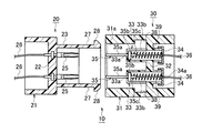
図1は本発明の一実施形態の半嵌合防止コネクタの要部を断面で示す斜視図、図2は同コネクタの嵌合前の状態を示す断面図、図3は同コネクタの嵌合途中の状態を示す断面図、図4は同コネクタの嵌合完了状態を示す断面図である。 FIG. 1 is a perspective view showing a main part of a half-fitting prevention connector according to an embodiment of the present invention in cross section, FIG. 2 is a cross-sectional view showing a state before the connector is fitted, and FIG. FIG. 4 is a cross-sectional view showing a completed state of the connector.
図1〜図4に示すように、半嵌合防止コネクタ10は、硬質合成樹脂製の雌ハウジング21の円筒状のフード部23内に一対の雌端子(一方の端子)25,25を有すると共に、円筒状のフード部23の上下部に一対のロックアーム27,27を延設する雌コネクタ(一方のコネクタ)20と、硬質合成樹脂製で円筒状の雄ハウジング31の円板状の隔壁32に一対の雄端子(他方の端子)35,35を有し、円筒状の雄ハウジング31の内周面31aの隔壁32の前側の位置にロックアーム27のロック突起(ロック部)28が係止・離脱される係止凹部(係止部)38を有する雄コネクタ(他方のコネクタ)30と、雄ハウジング31の隔壁32に設けられた一対の雄端子35,35の同軸上に設けられ、ロックアーム27のロック突起28が雄ハウジング31の係止凹部38に係止されるまでの両コネクタ20,30の半嵌合時において、ロックアーム27のロック突起28に当接した状態で雌ハウジング21を反嵌合方向Bに付勢して両コネクタ20,30を離間させ一対の圧縮コイルばね(弾性部材)39,39と、を備えている。
As shown in FIGS. 1 to 4, the half-
雌コネクタ20の円筒状の雌ハウジング21と雌ハウジング21より小径の円筒状のフード部23を仕切る円板状の隔壁22の中央の上下部には、一対の円筒状の雌端子25,25のフランジ状の基部25a,25aを埋設してある。各雌端子25の基端部25b,25bには電線26が接続されている。
A pair of cylindrical
また、雌ハウジング21のフード部23の上下部には、各一対のスリット23a,23aを形成してあり、この各一対のスリット23a,23a間には、先端にロック突起28を有した一対のロックアーム27,27を撓み変形自在に一体突出形成してある。この各ロックアーム27は、フード部23の先端より雄ハウジング31側に所定長さ延設してあり、そのロック突起28は雄ハウジング31の内周面31aをスライド(摺動)して係止凹部38に係止するようになっている。
A pair of slits 23a, 23a are formed on the upper and lower portions of the
雄コネクタ30の円筒状の雄ハウジング31の後側に位置する円板状の隔壁32の中央の上下部には、雄端子35と雄端子35の基端部35cに接続された電線36と圧縮コイルバネ39を収容する前面が閉塞された円筒状のバネ収容部33を隔壁32を連通するように一体突出形成してある。
On the upper and lower sides of the center of the disk-
上下一対の円筒状のバネ収容部33,33内には、各雄端子35の円板フランジ状の基部35bがスライド(摺動)自在に設けてあり、各雄端子35のピン状のタブ部35aは各バネ収容部33の前壁に形成された円形孔33aを貫通して外に露出している。また、上下一対の円筒状のバネ収容部33,33の上下側には、各ロックアーム27のロック突起28が挿入されて各雄端子35の円板フランジ状の基部35bが挿入されて押圧するための開口部33bをそれぞれ形成してある。さらに、各圧縮コイルばね39内に各端子35の円板フランジ状の基部35bと基端部35c及び電線36の一部が貫通した状態で各円筒状のバネ収容部33内に各圧縮コイルバネ39を収容してある。尚、各バネ収容部33の後端の開口部は、中央に円形孔34aを有したカバー34により閉塞されている。
A disk flange-
そして、図3に示すように、雌コネクタ20のロックアーム27のロック突起28が雄コネクタ30の雄ハウジング31の内周面31aの係止凹部38に係止されるまでの両コネクタ20,30の半嵌合時には、ロックアーム27のロック突起28の先端で雄端子35の円板フランジ状の基部35bを押圧して圧縮コイルバネ39を圧縮変形させ、また、図4に示すように、ロックアーム27のロック突起28が係止凹部38に係止される両コネクタ20,30の嵌合時に、圧縮コイルバネ39に対するロックアーム27のロック突起28による押圧が解除されて圧縮コイルバネ39が元の状態に戻るようになっている。即ち、雌コネクタ20のロックアーム27のロック突起28が係止される雄コネクタ30の雄ハウジング31の内周面31aの係止凹部38の位置が圧縮コイルバネ39が元の状態に戻る復元位置となっている。
Then, as shown in FIG. 3, both
また、雌,雄コネクタ20,30の半嵌合を防止するため、雌,雄コネクタ20,30の嵌合時の挿入力より圧縮コイルバネ39の反発力を強くすることにより、雌コネクタ20のロックアーム27のロック突起28が雄コネクタ30の雄ハウジング31の係止凹部38に係止されるまで、雌コネクタ20が圧縮コイルバネ39により雌端子25と雄端子35が接触しない位置まで戻され、半嵌合による雌コネクタ20の雌端子25と雄コネクタ30の雄端子35の導通を防止することができるようになっている。
Further, in order to prevent half-fitting of the female and
以上実施形態の半嵌合防止コネクタ10によれば、図3に示すように、雌,雄コネクタ20,30の半嵌合(中途嵌合)を防止するため、圧縮コイルバネ39は、雌コネクタ20の雌端子25と雄コネクタ30の雄端子35が離間する端子離脱力以上の反発力を持つことにより、雌コネクタ20のロックアーム27のロック突起28が雄コネクタ30の雄ハウジング31の係止凹部38に係止されるるまで、雌コネクタ20は雌端子25と雄コネクタ30の雄端子35が接触しない状態まで押し戻され、半嵌合での導通が無くなる。即ち、圧縮コイルバネ30の反発力(復元力)により雄コネクタ30に対して雌コネクタ20を反嵌合方向Bに付勢して雌,雄コネクタ20,30を離間させる。
According to the half-
また、図4に示すように、完全嵌合状態では、雌コネクタ20のロックアーム27のロック突起28が雄コネクタ30の雄ハウジング31の係止凹部38に係止されて収まることで、圧縮コイルバネ39の反発力が解放され、圧縮コイルバネ39に荷重(負荷)がかからなくなる。
Further, as shown in FIG. 4, in the fully-fitted state, the
このように、両コネクタ20,30の嵌合後に圧縮コイルバネ39に荷重がかからないため、圧縮コイルバネ39の耐久性が上がり、半嵌合防止コネクタ10の耐用年数を長くすることができる。また、端子離脱力以上のバネ強度でよくなり、コネクタ挿入力を小さくすることが可能となるため、取扱い性が良くなり、さらに、圧縮コイルバネ39を小さくすることができるため、コネクタ全体の小型化を図ることができる。
Thus, since the
尚、前記実施形態によれば、一対の雄端子に圧縮コイルバネをそれぞれ付けたが、一方の雄端子にのみ圧縮コイルバネを付けても良い。また、ロックアームも一対ではなく、3つ以上でも良く、ハウジングの形状も円筒状に限らず、矩形箱状等の形状でも良い。 In addition, according to the said embodiment, although the compression coil spring was each attached to a pair of male terminal, you may attach a compression coil spring only to one male terminal. Also, the lock arms may be three or more instead of a pair, and the shape of the housing is not limited to a cylindrical shape, and may be a rectangular box shape or the like.
10 半嵌合防止コネクタ
20 雌コネクタ(一方のコネクタ)
25 雌端子(一方の端子)
27 ロックアーム
28 ロック突起(ロック部)
30 雄コネクタ(他方のコネクタ)
35 雄端子(他方の端子)
38 係止凹部(係止部)
39 圧縮コイルバネ(弾性部材)
B 反嵌合方向
10 Half-
25 Female terminal (one terminal)
27
30 Male connector (the other connector)
35 Male terminal (the other terminal)
38 Locking recess (locking part)
39 Compression coil spring (elastic member)
B Counter mating direction
Claims (2)
前記一方のコネクタに嵌合した際に前記ロックアームのロック部が係止される係止部と他方の端子を有する他方のコネクタと、
前記他方のコネクタの他方の端子の近傍に設けられ、前記両コネクタの半嵌合時に前記一方のコネクタを反嵌合方向に付勢して該両コネクタを離間させる弾性部材と、を備え、
前記一方のコネクタのロックアームのロック部が前記他方のコネクタの係止部に係止されるまでの前記両コネクタの半嵌合時に、前記ロックアームにより前記弾性部材が押圧されて弾性変形し、
前記一方のコネクタのロックアームのロック部が前記他方のコネクタの係止部に係止される前記両コネクタの嵌合時に、前記弾性部材に対する前記ロックアームによる押圧が解除されて該弾性部材が元の状態に復元されるようにしたことを特徴とする半嵌合防止コネクタ。 One connector having one terminal and a lock arm;
The other connector having a locking portion and the other terminal where the lock portion of the lock arm is locked when fitted to the one connector,
An elastic member provided in the vicinity of the other terminal of the other connector, and biasing the one connector in a counter-fitting direction when the two connectors are half-fitted, and separating the two connectors;
At the time of half-fitting of the two connectors until the lock portion of the lock arm of the one connector is locked to the lock portion of the other connector, the elastic member is pressed and elastically deformed by the lock arm,
When the locking portions of the locking arm of the one connector are engaged with the engaging portions of the other connector, the pressing by the locking arm against the elastic member is released and the elastic member is A half-fitting prevention connector characterized by being restored to the state of.
前記他方のコネクタの他方の端子と同軸上に前記弾性部材を設け、前記他方のコネクタの係止部の位置が前記弾性部材の復元位置としたことを特徴とする半嵌合防止コネクタ。 The half-fitting prevention connector according to claim 1,
A half-fitting prevention connector, wherein the elastic member is provided coaxially with the other terminal of the other connector, and a position of a locking portion of the other connector is a restoring position of the elastic member.
Priority Applications (1)
| Application Number | Priority Date | Filing Date | Title |
|---|---|---|---|
| JP2017131639A JP6899268B2 (en) | 2017-07-05 | 2017-07-05 | Semi-fitting prevention connector |
Applications Claiming Priority (1)
| Application Number | Priority Date | Filing Date | Title |
|---|---|---|---|
| JP2017131639A JP6899268B2 (en) | 2017-07-05 | 2017-07-05 | Semi-fitting prevention connector |
Publications (2)
| Publication Number | Publication Date |
|---|---|
| JP2019016472A true JP2019016472A (en) | 2019-01-31 |
| JP6899268B2 JP6899268B2 (en) | 2021-07-07 |
Family
ID=65359375
Family Applications (1)
| Application Number | Title | Priority Date | Filing Date |
|---|---|---|---|
| JP2017131639A Active JP6899268B2 (en) | 2017-07-05 | 2017-07-05 | Semi-fitting prevention connector |
Country Status (1)
| Country | Link |
|---|---|
| JP (1) | JP6899268B2 (en) |
Cited By (1)
| Publication number | Priority date | Publication date | Assignee | Title |
|---|---|---|---|---|
| WO2023027005A1 (en) * | 2021-08-27 | 2023-03-02 | グンゼ株式会社 | Medical material |
Citations (6)
| Publication number | Priority date | Publication date | Assignee | Title |
|---|---|---|---|---|
| JPH09167656A (en) * | 1995-11-02 | 1997-06-24 | Harting Kg Aa | Coaxial plug connector |
| JP2001006812A (en) * | 1999-06-16 | 2001-01-12 | Yazaki Corp | Connector for preventing incomplete fitting |
| JP2001015213A (en) * | 1999-06-28 | 2001-01-19 | Yazaki Corp | Semi-fitting detection connector |
| JP2001160457A (en) * | 1999-12-01 | 2001-06-12 | Yazaki Corp | Half-fitting preventing connector |
| JP2001345147A (en) * | 2000-05-31 | 2001-12-14 | Yazaki Corp | Half fitting preventive connector |
| US7758370B1 (en) * | 2009-06-26 | 2010-07-20 | Corning Gilbert Inc. | Quick release electrical connector |
-
2017
- 2017-07-05 JP JP2017131639A patent/JP6899268B2/en active Active
Patent Citations (6)
| Publication number | Priority date | Publication date | Assignee | Title |
|---|---|---|---|---|
| JPH09167656A (en) * | 1995-11-02 | 1997-06-24 | Harting Kg Aa | Coaxial plug connector |
| JP2001006812A (en) * | 1999-06-16 | 2001-01-12 | Yazaki Corp | Connector for preventing incomplete fitting |
| JP2001015213A (en) * | 1999-06-28 | 2001-01-19 | Yazaki Corp | Semi-fitting detection connector |
| JP2001160457A (en) * | 1999-12-01 | 2001-06-12 | Yazaki Corp | Half-fitting preventing connector |
| JP2001345147A (en) * | 2000-05-31 | 2001-12-14 | Yazaki Corp | Half fitting preventive connector |
| US7758370B1 (en) * | 2009-06-26 | 2010-07-20 | Corning Gilbert Inc. | Quick release electrical connector |
Cited By (1)
| Publication number | Priority date | Publication date | Assignee | Title |
|---|---|---|---|---|
| WO2023027005A1 (en) * | 2021-08-27 | 2023-03-02 | グンゼ株式会社 | Medical material |
Also Published As
| Publication number | Publication date |
|---|---|
| JP6899268B2 (en) | 2021-07-07 |
Similar Documents
| Publication | Publication Date | Title |
|---|---|---|
| JP5542363B2 (en) | Electrical plug connector and locking curved member | |
| JP5876510B2 (en) | Electrical connector and connector system | |
| JP5863179B2 (en) | Waterproof connector | |
| WO2015002107A1 (en) | Rotary connector | |
| US9209561B2 (en) | Connector structure | |
| TWI624115B (en) | Socket electrical connector, plug electrical connector and combinations thereof | |
| KR101909830B1 (en) | Connector member and connector | |
| JP6914232B2 (en) | Connector structure | |
| US10658782B2 (en) | Stop spring for a contact device, electrical contact de-vice assembly as well as electrical connector | |
| WO2014175176A1 (en) | Connector | |
| JP2015170489A (en) | connector | |
| JP2018200765A (en) | connector | |
| EP3352308A1 (en) | Front cover device for power socket and power socket equipped with such a front cover device | |
| JP2019016472A (en) | Semi-mating prevention connector | |
| US11158972B2 (en) | Socket connector assembly | |
| JP6940345B2 (en) | connector | |
| JP6499135B2 (en) | Connector and connector assembly method | |
| JP6933534B2 (en) | Semi-fitting prevention connector | |
| JP6974051B2 (en) | Semi-fitting prevention connector | |
| JP2020126746A (en) | Connector structure | |
| JP2018186021A (en) | connector | |
| JP7096128B2 (en) | connector | |
| TWM547771U (en) | Socket electric connector, plug electric connector, and combination thereof | |
| JP6839609B2 (en) | connector | |
| JP2023074403A (en) | connector |
Legal Events
| Date | Code | Title | Description |
|---|---|---|---|
| A621 | Written request for application examination |
Free format text: JAPANESE INTERMEDIATE CODE: A621 Effective date: 20200617 |
|
| A977 | Report on retrieval |
Free format text: JAPANESE INTERMEDIATE CODE: A971007 Effective date: 20210305 |
|
| A131 | Notification of reasons for refusal |
Free format text: JAPANESE INTERMEDIATE CODE: A131 Effective date: 20210316 |
|
| A521 | Request for written amendment filed |
Free format text: JAPANESE INTERMEDIATE CODE: A523 Effective date: 20210421 |
|
| TRDD | Decision of grant or rejection written | ||
| A01 | Written decision to grant a patent or to grant a registration (utility model) |
Free format text: JAPANESE INTERMEDIATE CODE: A01 Effective date: 20210601 |
|
| A61 | First payment of annual fees (during grant procedure) |
Free format text: JAPANESE INTERMEDIATE CODE: A61 Effective date: 20210614 |
|
| R150 | Certificate of patent or registration of utility model |
Ref document number: 6899268 Country of ref document: JP Free format text: JAPANESE INTERMEDIATE CODE: R150 |
|
| S531 | Written request for registration of change of domicile |
Free format text: JAPANESE INTERMEDIATE CODE: R313531 |
|
| R350 | Written notification of registration of transfer |
Free format text: JAPANESE INTERMEDIATE CODE: R350 |