EP3259810B1 - Connector with damping element - Google Patents
Connector with damping element Download PDFInfo
- Publication number
- EP3259810B1 EP3259810B1 EP16703064.2A EP16703064A EP3259810B1 EP 3259810 B1 EP3259810 B1 EP 3259810B1 EP 16703064 A EP16703064 A EP 16703064A EP 3259810 B1 EP3259810 B1 EP 3259810B1
- Authority
- EP
- European Patent Office
- Prior art keywords
- plug connector
- damping element
- inner conductor
- connector
- conductor contact
- Prior art date
- Legal status (The legal status is an assumption and is not a legal conclusion. Google has not performed a legal analysis and makes no representation as to the accuracy of the status listed.)
- Active
Links
- 238000013016 damping Methods 0.000 title claims description 87
- 239000004020 conductor Substances 0.000 claims description 168
- 230000013011 mating Effects 0.000 claims description 56
- 238000003780 insertion Methods 0.000 claims description 51
- 230000037431 insertion Effects 0.000 claims description 51
- 239000000463 material Substances 0.000 claims description 12
- 230000000295 complement effect Effects 0.000 claims description 7
- 230000006835 compression Effects 0.000 claims description 6
- 238000007906 compression Methods 0.000 claims description 6
- 229920003023 plastic Polymers 0.000 claims description 5
- 239000004033 plastic Substances 0.000 claims description 5
- 239000012212 insulator Substances 0.000 description 85
- 238000000034 method Methods 0.000 description 7
- 229920001971 elastomer Polymers 0.000 description 4
- 238000004519 manufacturing process Methods 0.000 description 4
- 230000002238 attenuated effect Effects 0.000 description 3
- 230000008878 coupling Effects 0.000 description 2
- 238000010168 coupling process Methods 0.000 description 2
- 238000005859 coupling reaction Methods 0.000 description 2
- 238000002788 crimping Methods 0.000 description 2
- 230000000694 effects Effects 0.000 description 2
- 239000000806 elastomer Substances 0.000 description 2
- 238000009434 installation Methods 0.000 description 2
- 239000012811 non-conductive material Substances 0.000 description 2
- 238000003825 pressing Methods 0.000 description 2
- 238000005476 soldering Methods 0.000 description 2
- 238000010276 construction Methods 0.000 description 1
- 238000005520 cutting process Methods 0.000 description 1
- 230000001419 dependent effect Effects 0.000 description 1
- 238000011161 development Methods 0.000 description 1
- 230000018109 developmental process Effects 0.000 description 1
- 230000001747 exhibiting effect Effects 0.000 description 1
- 239000000615 nonconductor Substances 0.000 description 1
- 238000009420 retrofitting Methods 0.000 description 1
Images


Classifications
-
- H—ELECTRICITY
- H01—ELECTRIC ELEMENTS
- H01R—ELECTRICALLY-CONDUCTIVE CONNECTIONS; STRUCTURAL ASSOCIATIONS OF A PLURALITY OF MUTUALLY-INSULATED ELECTRICAL CONNECTING ELEMENTS; COUPLING DEVICES; CURRENT COLLECTORS
- H01R13/00—Details of coupling devices of the kinds covered by groups H01R12/70 or H01R24/00 - H01R33/00
- H01R13/46—Bases; Cases
- H01R13/53—Bases or cases for heavy duty; Bases or cases for high voltage with means for preventing corona or arcing
-
- H—ELECTRICITY
- H01—ELECTRIC ELEMENTS
- H01R—ELECTRICALLY-CONDUCTIVE CONNECTIONS; STRUCTURAL ASSOCIATIONS OF A PLURALITY OF MUTUALLY-INSULATED ELECTRICAL CONNECTING ELEMENTS; COUPLING DEVICES; CURRENT COLLECTORS
- H01R13/00—Details of coupling devices of the kinds covered by groups H01R12/70 or H01R24/00 - H01R33/00
- H01R13/46—Bases; Cases
- H01R13/502—Bases; Cases composed of different pieces
- H01R13/5025—Bases; Cases composed of different pieces one or more pieces being of resilient material
-
- H—ELECTRICITY
- H01—ELECTRIC ELEMENTS
- H01R—ELECTRICALLY-CONDUCTIVE CONNECTIONS; STRUCTURAL ASSOCIATIONS OF A PLURALITY OF MUTUALLY-INSULATED ELECTRICAL CONNECTING ELEMENTS; COUPLING DEVICES; CURRENT COLLECTORS
- H01R2103/00—Two poles
-
- H—ELECTRICITY
- H01—ELECTRIC ELEMENTS
- H01R—ELECTRICALLY-CONDUCTIVE CONNECTIONS; STRUCTURAL ASSOCIATIONS OF A PLURALITY OF MUTUALLY-INSULATED ELECTRICAL CONNECTING ELEMENTS; COUPLING DEVICES; CURRENT COLLECTORS
- H01R24/00—Two-part coupling devices, or either of their cooperating parts, characterised by their overall structure
- H01R24/38—Two-part coupling devices, or either of their cooperating parts, characterised by their overall structure having concentrically or coaxially arranged contacts
Definitions
- the outer conductor part may be in the form of a housing, such as an outer conductor housing, formed and / or grounded and thus shield the inner conductor.
- a coaxial connector is connectable to a coaxial cable, wherein the outer conductor of the coaxial cable is electrically contacted with the outer conductor portion of the connector, and an inner conductor of the coaxial cable is electrically contacted with the inner conductor contact of the connector.
- Connectors generally serve to releasably connect electrical leads to carry power and / or electrical signals when connected.
- a first connector in the form of a socket part is verkuppelt with a second connector in the form of a plug part for forming a plug connection.
- High-current connectors are used to transmit high electrical currents, for example. With a current greater than 50 A or 100 A, and are the Example used in motor vehicles with electric drive or hybrid drive.
- the inner conductor contact of the mating connector having one or more in the insertion direction S projecting pins, which are inserted in the insertion direction in a receiving opening of the connector. In the receiving opening is the excellentleitcard the female part.
- an electrical connector for making a plug connection with a mating connector includes a housing, a seal disposed on the housing, and a seal retainer disposed on the housing and associated with the seals.
- the seal holder is movably disposed on the housing to be moved in the direction of the seal and pressed against the seal in the manufacture of the connector with the mating connector. Due to the elastic stop a production-related movement space of the electrical connector can be reduced or eliminated at the mating connector, whereby the connector is less sensitive to mechanical influences, in particular vibrations. However, this only prevents a relative movement between the connector and the mating connector. Relative movements between an insulator part and an inner conductor contact or an outer conductor due to an existing axial play when inserting the mating connector can not be prevented hereby.
- the damping element for example.
- an elastically compressible soft component provided on the connector so that it is compressed at a pressure acting on the plug-side end of the connector, while the inner conductor contact attenuated against the insulator part and / or the insulator part attenuated against the outer conductor part is pushed.
- the invention is based on the knowledge that with conventional connectors manufacturing reasons regularly a considerable axial clearance between the inner conductor contact and the insulator part or between the insulator part and the outer conductor part is present. This axial play can lead to considerable relative movements of the insulator part with respect to the outer conductor part or with respect to the inner conductor contact under mechanical loads, such as vibrations, which causes the above-described increased wear of the connector.
- the insulator part of the connector according to the invention can have a predetermined axial mobility with respect to the outer conductor part and / or with respect to the inner conductor contact, so that a particularly simple and quick installation of the connector is possible.
- the connector according to the invention can therefore be mounted quickly and easily and at the same time ensures a high stability and a good axial fixation of the insulator part between the inner conductor contact and the outer conductor part, so that vibrations originating from the outer conductor part can not lead to relative movements between the individual connector components.
- the damping element exerts direct or indirect pressure in the insertion on the inner conductor contact and / or pressure on the insulator part when inserting the mating connector, so that the inner conductor part in the direction of the insulator part and / or the insulator part in the direction of the External conductor part is urged.
- the elastic damping element compressed axially (in the insertion direction) and thereby restricted in its internal mobility.
- the elastic damping element is not directly applied to a current-carrying element, such as the inner conductor contact. Rather, the damping element when inserting the mating connector should exert only indirectly pressure in the insertion direction on the inner conductor contact and thereby press axially against the insulator part.
- an axially movable intermediate element made of a rigid material may be provided between the damping element and the inner conductor contact.
- the damping element exerts immediate pressure in the insertion direction on the insulator part.
- pressure is initially exerted indirectly on the inner conductor contact by the compression of the damping element in the plug-in direction, and pressure is additionally exerted indirectly and / or directly on the insulator part once a predetermined compression state of the damping element has been reached.
- an axial material thickness of the damping element is variably arranged, wherein a portion of high material thickness for applying pressure to the inner conductor contact and a portion of low material thickness provided for exerting pressure on the insulator part is.
- pressure is applied to the insulator part during the insertion process only when the damping element is already lower by the difference between the high-material-strength section and the section Material thickness is compressed.
- the mating connector facing the front surface of the damping element has a convexly curved, in particular a rounded contour.
- the connector according to the invention preferably has an axial clearance between the inner conductor contact and the insulator part and / or between the insulator part and the outer conductor part, wherein at least the clearance between the inner conductor contact and the insulator part, and preferably also the clearance between the insulator part and the outer conductor part can be reduced or eliminated by exerting pressure on the damping element in the insertion direction.
- a playful construction of the connector allows for easier and faster installation of the connector.
- the damping element forms a counterpart connector when plugging facing front boundary surface of the connector.
- a counter-pressure surface of the mating connector can exert immediate pressure on the damping element.
- a front mounted on the connector and preferably exposed to the environment damping element can still be attached to the connector after assembly of inner conductor contact and insulator part in the outer conductor housing.
- a subsequent retrofitting of conventional connectors by attaching the damping element is possibly still possible.
- the damping element forms the leading during the insertion process interface of the connector.
- the damping element With regard to a uniform and planar pressure exerted on the inner conductor contact and / or on the insulator part, it has proven to be advantageous for the damping element to rotate around an insertion opening of the connector for inserting a contact element of the mating connector.
- the damping element is an annular soft rubber part or elastomer part.
- the sliding element is preferably formed as a rigid, preferably at least partially annular plastic body, on the front end of the damping element is sprayed from an elastomer or rubber material.
- the insulator part has on its front side an at least partially annular guide groove whose groove bottom is formed by the inner conductor contact.
- the guide groove has a substantially axial course, so that the sliding element is axially displaceable therein, wherein it abuts against the inner conductor contact.
- the guide groove may have a holding mechanism, so that the sliding element is held axially displaceable in the guide groove and can not fall out.
- the holding mechanism may be formed in the form of a latching mechanism, wherein the sliding element may have a latching projection and the guide groove may have a latching recess or vice versa.
- the elastically compressible damping element between the insulator part and the outer conductor part is arranged.
- the insulator part When inserting the mating connector, the insulator part is pressed in the direction of the outer conductor part, whereby the damping element is compressed in the insertion direction, and thereby the mobility between the insulator part and the outer conductor part is limited.
- the damping element has a substantially planar shape and is arranged between a substantially planar contact surface of the outer conductor part and a counter-pressure surface of the insulator part.
- a substantially round contour of the damping element has proved to be particularly advantageous.
- a more than one inner conductor contact exhibiting connector may also have more than one damping element.
- Damage to the insulator part due to excessive pressure can be effectively prevented by variably setting the dimension of the damping element in the insertion direction S, wherein a central region of the damping element is thicker than an edge region of the damping element.
- a central region of the damping element is thicker than an edge region of the damping element.
- the connector according to the second embodiment is preferably an angle connector in which a main axis H of the inner conductor contact and / or the insulator part extends transversely, in particular approximately perpendicular to the insertion direction, so that the current-carrying inner conductor can be led away transversely to the insertion direction of the mating connector.
- the inner conductor contact preferably has, on the one hand, a contact element for contacting the mating contact element of the mating connector and, on the other hand, a rod-shaped conductor part extending from the contact element along the main axis H, which can be connected to the inner conductor of a coaxial cable.
- the damping element preferably has such a large dimension in the uncompressed state in the plugging direction that the inner conductor contact and / or the insulator part at least in sections by the damping element with respect Main axis is deflected. Only by inserting the mating connector of the inner conductor contact and / or the insulator part is fed back under compression of the damping element in an undeflected position in which the mobility of the inner conductor contact and / or the insulator part with respect to. The outer conductor part is limited.
- the invention relates to a connector assembly having a connector according to the invention and a mating connector formed complementary thereto, which is configured such that when inserted into the connector, the damping element of the connector elastically compresses and thereby a mobility of the insulator member relative to the inner conductor contact and / or the outer conductor part is reduced.
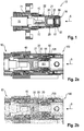
- a first embodiment of a connector 10 according to the invention is shown in a longitudinal sectional view.
- the connector 10 consists of an inner conductor contact 20, which is circulated by an insulator part 30 made of a non-conductor, such as plastic.
- the insulator part 30 prevents the inner conductor contact 20 from coming into electrical contact with an outer conductor part 40 of the connector 10.
- the connector 10 is connected to a coaxial cable 70, wherein the shield 71 of the coaxial cable 70 is electrically coupled to the outer conductor portion 40 of the connector and the inner conductor 72 of the coaxial cable 70 is electrically coupled to the inner conductor contact 20 of the connector 10, for example by soldering or crimping ,
- the inner conductor contact 20 is plug-shaped as a socket formed with a contact spring into which a contact element 101 of a mating connector 100 in the form of a contact pin for making an electrical contact can be inserted.
- a contact element 101 of a mating connector 100 in the form of a contact pin for making an electrical contact can be inserted.
- FIGS. 2a and 2b is the entire connector of connector 10 and associated mating connector 100 shown.
- the inner conductor contact 20 When assembling the connector 10, the inner conductor contact 20 is first connected to the inner conductor 72 of the coaxial cable 70, for example by soldering. Subsequently, the inner conductor contact 20 is inserted into the insulator part 30 until a projection of the insulator part 30 engages in a recess 25 of the inner conductor contact 20.
- the axial dimension of the recess 25 is set up such that a relative movement between insulator part 30 and inner conductor contact 20 within the framework of a predetermined axial play 21 is possible. This facilitates the attachment of the insulator part 30 to the inner conductor contact 20.
- the outer conductor part 40 of the connector for example, by pressing or crimping attached to this cable assembly, so that the outer conductor part 40, the outer conductor 71 of the cable 70 electrically contacted.
- the outer conductor part 40 is movable relative to the insulator part 30.
- the axial games 21, 22 allow for conventional connectors even after pairing with the complementary mating connector still relative movements between the inner conductor contact 20, the insulator part 30 and the outer conductor part 40, which has an increased material wear result, especially if the connector high mechanical loads such is exposed to vibrations.
- an elastically compressible damping element 50 is provided on the connector 10 according to the invention.
- This is compressed, whereby the mobility of the inner conductor contact 20 with respect to.
- the insulator portion 30 and / or the mobility of the insulator part with respect to the outer conductor part 40 is reduced or eliminated altogether.
- the finished plug state with completely eliminated axial play 21, 22 is in Fig. 2b shown while in Fig. 2a a position in the course of insertion of the mating connector 100 is shown, in which the counter-pressure surface 105 of the mating connector 100 while already applied to the damping element 50, but this is not fully compressed.
- the damping element 50 is provided on the connector 10 in such a way that it indirectly transmits the pressure emitted by the mating connector 100 during insertion to the inner conductor contact 20 and directly to the insulator part 30.
- the inner conductor contact 20, the insulator part 30 and the outer conductor part 40 are pushed together in the course of the insertion process, so that the axial Games 21 and 22 are eliminated and a rigid and immovable connection between the inner conductor contact 20, the insulator part 30 and the outer conductor contact is made.
- the damping element 50 forms the leading during insertion of the mating connector front surface of the connector to which by the in the FIGS. 2a and 2b shown counter-pressure surface 105 of the mating connector 100 pressure is exercisable.
- the front surface of the damping element 50 is not flat, but arranged convexly curved, so that in the course of the insertion process first a portion 55 of high material density comes into contact with the counter-pressure surface 105 and the sliding member 50 urges in the direction of the inner conductor contact 20. Subsequently, a portion 56 of low material density which bears directly against the insulator part 30 comes into contact with the counter-pressure surface 105 and presses the insulator part in the direction of the outer conductor part 40. Alternatively or additionally, the insulator part 30 becomes indirectly via the inner conductor part 20 in the direction of a contact surface of the outer conductor part 40 pressed.
- the connector 10 and the Gegenteckverbinder 100 form-locking or non-positively acting connecting means, such as screws, brackets or clamps, by means of which the mating connector, starting from the position according to Fig. 2a in the position according to Fig. 2b can be pulled.
- the connecting means also prevent accidental release of the connector.
- Fig. 4 shows a slightly modified embodiment of a connector 10 'according to the invention, in which the sliding member 60', on the front end of which Damping element 50 is sprayed, is not held axially displaceable in a guide groove of the insulator member 30, but in a radial guide 32 ', which rests radially outward on the sliding member 60'.
- the rear end 61 of the sliding member 60 ' abuts the inner conductor contact 20, while the damping element 50 formed as a soft component can not come into direct electrical contact with a current-carrying part.
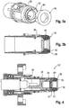
- Fig. 5 shows a second embodiment of a connector 10 "according to the invention.
- This connector is designed as an angle plug or an angle bushing, in which the main axis H of the inner conductor contact 120 or the insulator part 130 transversely, in particular perpendicular to the insertion direction S. In this way, the inner conductor perpendicular to the insertion direction S.
- the inner conductor contact 120 of the second embodiment has, on the one hand, a contact element 122 with contact spring for contacting one or more contact pins 101 'of the mating connector 100' and, on the other hand, a rod-shaped extending along the main axis H starting from the contact element 122 Ladder part 121 which is connectable to the inner conductor 72 of the coaxial cable 70.
- the inner conductor contact 120 is first connected to the inner conductor 72 of the coaxial cable to produce the connector 10 ", then the insulator part 130 is attached to the inner conductor contact 120.
- the arrangement of insulator part 130 and inner conductor contact 120 is along the main axis H perpendicular to the Plug-in direction S extends, inserted into a pipe section 141 of the outer conductor part 140 (see Fig. 8 ).
- a damping element 51 is arranged in the form of an elastically compressible soft component.
- the connector may also have more than one, for example. Two or three damping elements 51.
- the damping element 51 is substantially disc-shaped and has a central portion with a larger dimension in the insertion direction S as the edge portions of the damping element 51. In other words, a curvature of the damping element 51 projects into a mounting space of the outer conductor part 140 for receiving the insulator part 130.
- connection position the insulator part 130 is substantially immovable with respect to.
- the outer conductor part 140 is arranged. Strong vibrations are damped in this connection position by the damping element 51, whereby wear of insulator part 130 and outer conductor part 140 is reliably minimized.
- the damping element 50, 51 is not necessarily annular or disc-shaped.
- a connector depending on the size and number of inner conductor contacts, have more than one damping element. According to the invention it is important that the damping element is provided on the connector so that it is compressed elastically only when mating with the mating connector, and a wear-promoting mobility between the insulator part, the inner conductor contact and the outer conductor part is thus eliminated only during manufacture of the finished connector.
Description
Die Erfindung betrifft einen Steckverbinder, insbesondere einen Hochstrom-Steckverbinder, mit einem Innenleiterkontakt zur Stromführung, einem Außenleiterteil und einem den Innenleiterkontakt von dem Außenleiterteil beabstandet haltenden Isolatorteil, wobei ein elastisch komprimierbares Dämpfungselement derart an dem Steckverbinder vorgesehen ist, dass es beim Einstecken eines komplementären Gegensteckverbinders in den Steckverbinder in einer Einsteckrichtung elastisch komprimierbar ist, gemäß dem Oberbegriff von Anspruch 1.The invention relates to a connector, in particular a high-current connector, with an inner conductor contact for current conduction, an outer conductor part and an inner conductor contact spaced from the outer conductor part holding insulator part, wherein an elastically compressible damping element is provided on the connector, that when inserting a complementary mating connector in the plug connector in an insertion direction is elastically compressible, according to the preamble of claim 1.
Während der Innenleiterkontakt zur Stromführung vorgesehen ist, kann das Außenleiterteil in Form eines Gehäuses, wie etwa eines Außenleitergehäuses, gebildet und/oder geerdet sein und damit den Innenleiter abschirmen. Ein solcher Koaxial-Steckverbinder ist an ein Koaxialkabel ankoppelbar, wobei der Außenleiter des Koaxialkabels elektrisch mit dem Außenleiterteil des Steckverbinders kontaktiert wird, und ein Innenleiter des Koaxialkabels elektrisch mit dem Innenleiterkontakt des Steckverbinders kontaktiert wird.While the inner conductor contact is provided for current conduction, the outer conductor part may be in the form of a housing, such as an outer conductor housing, formed and / or grounded and thus shield the inner conductor. Such a coaxial connector is connectable to a coaxial cable, wherein the outer conductor of the coaxial cable is electrically contacted with the outer conductor portion of the connector, and an inner conductor of the coaxial cable is electrically contacted with the inner conductor contact of the connector.
Steckverbinder dienen allgemein zum lösbaren Verbinden von elektrischen Leitungen, um im verbundenen Zustand Strom und/oder elektrische Signale zu übertragen. Dabei wird ein erster Steckverbinder in Form eines Buchsenteils mit einem zweiten Steckverbinder in Form eines Steckerteils zum Bilden einer Steckverbindung verkuppelt. Hochstromsteckverbinder dienen zum Übertragen von hohen elektrischen Strömen, bspw. mit einer Stromstärke von mehr als 50 A oder 100 A, und werden zum Beispiel in Kraftfahrzeugen mit Elektroantrieb oder Hybridantrieb eingesetzt. Dabei kann der Innenleiterkontakt des Gegensteckverbinders einen oder mehrere in der Einsteckrichtung S vorstehende Kontaktstifte aufweisen, die in der Einsteckrichtung in eine Aufnahmeöffnung des Steckverbinders eingesteckt werden. In der Aufnahmeöffnung befindet sich der Innenleitkontakt des Buchsenteils.Connectors generally serve to releasably connect electrical leads to carry power and / or electrical signals when connected. In this case, a first connector in the form of a socket part is verkuppelt with a second connector in the form of a plug part for forming a plug connection. High-current connectors are used to transmit high electrical currents, for example. With a current greater than 50 A or 100 A, and are the Example used in motor vehicles with electric drive or hybrid drive. In this case, the inner conductor contact of the mating connector having one or more in the insertion direction S projecting pins, which are inserted in the insertion direction in a receiving opening of the connector. In the receiving opening is the Innenleitkontakt the female part.
Um zu verhindern, dass der Innenleiterkontakt in elektrischen Kontakt mit dem Außenleiterteil kommen kann, wird der Innenleiterkontakt regelmäßig von einem Isolatorteil aus einem nichtleitenden Material, wie etwa Kunststoff, gehalten, wobei das Isolatorteil zwischen dem Innenleiterkontakt und dem Außenleiterteil angeordnet ist. Beim Zusammenbau des Steckverbinders wird zunächst das Isolatorteil an dem Innenleiterkontakt angebracht, bspw. mittels einer Rastverbindung oder einer anderen form- bzw. kraftschlüssigen Verbindung, und anschließend wird die Baugruppe aus Isolatorteil und Innenleiterkontakt an dem Außenleiterteil befestigt, bspw. ebenfalls mittels einer Rastverbindung oder einer anderen form- bzw. kraftschlüssigen Verbindung.In order to prevent the inner conductor contact from coming into electrical contact with the outer conductor part, the inner conductor contact is regularly held by an insulator part made of a non-conductive material, such as plastic, the insulator part being arranged between the inner conductor contact and the outer conductor part. When assembling the connector, the insulator part is first attached to the inner conductor contact, for example. By means of a locking connection or other positive or non-positive connection, and then the assembly of insulator and inner conductor contact is attached to the outer conductor part, for example. Also by means of a locking connection or a other positive or non-positive connection.
Es hat sich allerdings herausgestellt, dass ein derart aufgebauter Steckverbinder zu einem erhöhten Verschleiß neigt, wenn er hohen mechanischen Belastungen ausgesetzt ist. Herkömmliche Hochstromsteckverbinder müssen aus diesem Grund regelmäßig gewartet werden, und von Verschleiß betroffene Bauteile, wie etwa Innenleiterkontakte oder Isolierteile, müssen regelmäßig ausgetauscht werden.However, it has been found that such a constructed connector tends to increase wear when it is exposed to high mechanical loads. For this reason, conventional high-current connectors must be regularly maintained, and components subject to wear, such as inner conductor contacts or insulating parts, must be replaced regularly.
Aus der
In Anbetracht der beschriebenen Probleme ist es die Aufgabe der vorliegenden Erfindung, einen zur Übertragung von hohen Stromstärken geeigneten Steckverbinder bereitzustellen, der auch unter hohen mechanischen Belastungen, wie etwa starken Vibrationen, einem möglichst geringen Verschleiß unterliegt, und auf diese Weise die Haltbarkeit von Hochstromsteckverbindern zu erhöhen.In view of the described problems, it is the object of the present invention to provide a connector suitable for transmitting high currents, which is subject to as little wear as possible under high mechanical loads, such as strong vibrations, and in this way to the durability of high current connectors increase.
Diese Aufgabe wird durch einen Steckverbinder der o.g. Art mit den in Anpruch 1 gekennzeichneten Merkmalen 1 gelöst. Vorteilhafte Weiterbildungen der Erfindung sind in den abhängigen Ansprüchen beschrieben.This object is achieved by a connector of the above-mentioned. Art solved with the features indicated in claim 1 features 1. Advantageous developments of the invention are described in the dependent claims.
Dazu ist es bei einem Steckverbinder der o.g. Art erfindungsgemäß vorgesehen, dass das Dämpfungselement beim Einstecken des Gegensteckverbinders unmittelbar oder mittelbar Druck in der Einsteckrichtung auf den Innenleiterkontakt und/oder Druck auf das Isolatorteil ausübt und dabei eine Beweglichkeit des Isolatorteils gegenüber dem Innenleiterkontakt und/oder gegenüber dem Außenleiterteil verringert.It is with a connector of o.g. Art according to the invention provided that the damping element during insertion of the mating connector directly or indirectly exerts pressure in the insertion on the inner conductor contact and / or pressure on the insulator part and thereby reduces mobility of the insulator member relative to the inner conductor contact and / or to the outer conductor part.
Mit anderen Worten ist das Dämpfungselement, bspw. in Form einer elastisch komprimierbaren Weichkomponente, derart am Steckverbinder vorgesehen, dass es bei einer Druckeinwirkung auf das steckseitige Ende des Steckverbinders komprimiert wird, und dabei der Innenleiterkontakt gedämpft gegen das Isolatorteil und/oder das Isolatorteil gedämpft gegen das Außenleiterteil geschoben wird.In other words, the damping element, for example. In the form of an elastically compressible soft component, provided on the connector so that it is compressed at a pressure acting on the plug-side end of the connector, while the inner conductor contact attenuated against the insulator part and / or the insulator part attenuated against the outer conductor part is pushed.
Die Erfindung geht auf die Erkenntnis zurück, dass bei herkömmlichen Steckverbindern herstellungsbedingt regelmäßig ein beträchtliches axiales Spiel zwischen dem Innenleiterkontakt und dem Isolatorteil bzw. zwischen dem Isolatorteil und dem Außenleiterteil vorhanden ist. Dieses axiale Spiel kann zu erheblichen Relativbewegungen des Isolatorteils bzgl. des Außenleiterteils oder bzgl. des Innenleiterkontakts bei mechanischen Belastungen, wie etwa Vibrationen, führen, wodurch der oben beschriebene erhöhte Verschleiß des Steckverbinders hervorgerufen wird.The invention is based on the knowledge that with conventional connectors manufacturing reasons regularly a considerable axial clearance between the inner conductor contact and the insulator part or between the insulator part and the outer conductor part is present. This axial play can lead to considerable relative movements of the insulator part with respect to the outer conductor part or with respect to the inner conductor contact under mechanical loads, such as vibrations, which causes the above-described increased wear of the connector.
Es wurde bereits versucht, diese Beweglichkeit des Isolatorteils dadurch einzuschränken, dass die Verbindung zwischen dem Isolatorteil und dem Innenleiterkontakt und/oder dem Außenleiterteil stabiler bzw. steifer eingerichtet wird. Eine sehr steife und unbewegliche Verbindung zwischen dem Isolatorteil und dem Innenleiterkontakt und/oder dem Außenleiterteil erschwert jedoch eine schnelle und einfache Montage des Steckverbinders. Das Isolatorteil des erfindungsgemäßen Steckverbinders kann demgegenüber (vor dem Verkuppeln mit dem Gegensteckverbinder) eine vorgegebene axiale Beweglichkeit bzgl. des Außenleiterteils und/oder bzgl. des Innenleiterkontakts aufweisen, so dass eine besonders einfache und schnelle Montage des Steckverbinders möglich ist. Die den beobachteten Verschleiß hervorrufende Beweglichkeit des Isolatorteils wird erfindungsgemäß erst durch das Verkuppeln des Gegensteckverbinders mit dem Steckverbinder und die damit verbundene axiale Druckausübung auf den Steckverbinder verringert oder vollständig beseitigt. Dies gelingt erfindungsgemäß dadurch, dass ein elastisches Dämpfungselement derart an dem Steckverbinder vorgesehen ist, dass es beim Einstecken des Gegensteckverbinders aufgrund des dadurch ausgeübten Drucks in der Einsteckrichtung komprimiert wird, und dadurch das Isolatorteil, der Innenleiterkontakt und/oder das Außenleiterteil in axialer Richtung zusammengepresst werden.It has already been attempted to limit this mobility of the insulator part in that the connection between the insulator part and the inner conductor contact and / or the outer conductor part is made more stable or stiffer. However, a very rigid and immovable connection between the insulator part and the inner conductor contact and / or the outer conductor part makes it difficult to quickly and easily mount the connector. In contrast, the insulator part of the connector according to the invention can have a predetermined axial mobility with respect to the outer conductor part and / or with respect to the inner conductor contact, so that a particularly simple and quick installation of the connector is possible. The observed wear causing mobility of the insulator part is inventively reduced only by the coupling of the mating connector with the connector and the associated axial pressure on the connector or completely eliminated. This is inventively achieved in that an elastic damping element is provided on the connector so that it is compressed during insertion of the mating connector due to the pressure exerted in the insertion direction, and thereby the insulator part, the inner conductor contact and / or the outer conductor part are compressed in the axial direction ,
Der erfindungsgemäße Steckverbinder kann deshalb schnell und einfach montiert werden und gewährleistet gleichzeitig im zusammengesteckten Zustand eine hohe Stabilität und eine gute axiale Fixierung des Isolatorteils zwischen dem Innenleiterkontakt und dem Außenleiterteils, so dass vom Außenleiterteil ausgehende Vibrationen nicht zu Relativbewegungen zwischen den einzelnen Steckverbinderkomponenten führen können.The connector according to the invention can therefore be mounted quickly and easily and at the same time ensures a high stability and a good axial fixation of the insulator part between the inner conductor contact and the outer conductor part, so that vibrations originating from the outer conductor part can not lead to relative movements between the individual connector components.
Bei einer bevorzugten Ausführungsform der Erfindung übt das Dämpfungselement beim Einstecken des Gegensteckverbinders unmittelbar oder mittelbar Druck in der Einsteckrichtung auf den Innenleiterkontakt und/oder Druck auf das Isolatorteil aus, so dass das Innenleiterteil in Richtung auf das Isolatorteil und/oder das Isolatorteil in Richtung auf das Außenleiterteil gedrängt wird. Durch den Einsteckvorgang des Gegensteckverbinders wird der Steckverbinder damit unter Dämpfung durch das elastische Dämpfungselement axial (in Einsteckrichtung) zusammengedrückt und dadurch in seiner inneren Beweglichkeit eingeschränkt.In a preferred embodiment of the invention, the damping element exerts direct or indirect pressure in the insertion on the inner conductor contact and / or pressure on the insulator part when inserting the mating connector, so that the inner conductor part in the direction of the insulator part and / or the insulator part in the direction of the External conductor part is urged. Through the insertion of the mating connector of the connector is thus under damping by the elastic damping element compressed axially (in the insertion direction) and thereby restricted in its internal mobility.
Vorzugsweise weist der Steckverbinder mit dem Gegensteckverbinder zusammenwirkende formschlüssige und/oder kraftschlüssige Verbindungsmittel wie etwa Schrauben, Klemmbügel o.dgl. auf, um den Gegensteckverbinder beim Einstecken unter Kompression des Dämpfungselements ausreichend weit an den Steckverbinder heranführen bzw. ausreichend weit in den Steckverbinder hineinschieben zu können. Um ein übermäßiges Zusammenpressen des Dämpfungselements durch die Verbindungsmittel zu verhindern, kann ein entsprechender Anschlag am Steckverbinder vorgesehen sein.Preferably, the connector with the mating connector cooperating positive and / or non-positive connection means such as screws, clamps or the like. on to sufficiently introduce the mating connector when plugging under compression of the damping element to the connector or to push sufficiently far into the connector can. In order to prevent excessive compression of the damping element by the connecting means, a corresponding stop may be provided on the connector.
Dabei hat es sich als zweckmäßig erwiesen, dass das elastische Dämpfungselement nicht unmittelbar an einem stromführenden Element, wie etwa dem Innenleiterkontakt, anliegt. Vielmehr sollte das Dämpfungselement beim Einstecken des Gegensteckverbinders nur mittelbar Druck in der Einsteckrichtung auf den Innenleiterkontakt ausüben und diesen dadurch axial gegen das Isolatorteil drücken. Zu diesem Zweck kann ein axial bewegliches Zwischenelement aus einem starren Material zwischen dem Dämpfungselement und dem Innenleiterkontakt vorgesehen sein. Andererseits hat es sich als besonders vorteilhaft erwiesen, dass das Dämpfungselement unmittelbar Druck in der Einsteckrichtung auf das Isolatorteil ausübt. Bei einer besonders bevorzugten Ausführungsform der Erfindung wird durch die Kompression des Dämpfungselements in der Einsteckrichtung zunächst mittelbar Druck auf den Innenleiterkontakt ausgeübt und ab Erreichen eines vorgegebenen Kompressionszustands des Dämpfungselements wird zusätzlich mittelbar und/oder unmittelbar Druck auf das Isolatorteil ausgeübt.It has proved to be expedient that the elastic damping element is not directly applied to a current-carrying element, such as the inner conductor contact. Rather, the damping element when inserting the mating connector should exert only indirectly pressure in the insertion direction on the inner conductor contact and thereby press axially against the insulator part. For this purpose, an axially movable intermediate element made of a rigid material may be provided between the damping element and the inner conductor contact. On the other hand, it has proved to be particularly advantageous that the damping element exerts immediate pressure in the insertion direction on the insulator part. In a particularly preferred embodiment of the invention, pressure is initially exerted indirectly on the inner conductor contact by the compression of the damping element in the plug-in direction, and pressure is additionally exerted indirectly and / or directly on the insulator part once a predetermined compression state of the damping element has been reached.
Um eine derartige stufige Druckausübung zu ermöglichen, hat es sich als zweckmäßig erwiesen, dass eine axiale Materialstärke des Dämpfungselements variabel eingerichtet ist, wobei ein Abschnitt hoher Materialstärke zum Ausüben von Druck auf den Innenleiterkontakt und ein Abschnitt geringer Materialstärke zum Ausüben von Druck auf das Isolatorteil vorgesehen ist. In diesem Fall wird während des Einsteckvorgangs erst dann Druck auf das Isolatorteil ausgeübt, wenn das Dämpfungselement bereits um die Differenz zwischen dem Abschnitt hoher Materialstärke und dem Abschnitt geringer Materialstärke zusammengedrückt ist. Dies führt zu einer besonders stabilen und starren Gesamtanordnung aus Steckverbinder und damit verbundenem Gegensteckverbinder. Vorzugsweise hat die dem Gegensteckverbinder zugewandte Frontfläche des Dämpfungselements eine konvex gewölbte, insbesondere eine abgerundete Kontur.In order to enable such a stepped pressure application, it has proved expedient that an axial material thickness of the damping element is variably arranged, wherein a portion of high material thickness for applying pressure to the inner conductor contact and a portion of low material thickness provided for exerting pressure on the insulator part is. In this case, pressure is applied to the insulator part during the insertion process only when the damping element is already lower by the difference between the high-material-strength section and the section Material thickness is compressed. This leads to a particularly stable and rigid overall arrangement of connectors and associated mating connector. Preferably, the mating connector facing the front surface of the damping element has a convexly curved, in particular a rounded contour.
Im unkomprimierten Zustand des Dämpfungselements weist der erfindungsgemäße Steckverbinder vorzugsweise ein axiales Spiel zwischen dem Innenleiterkontakt und dem Isolatorteil und/oder zwischen dem Isolatorteil und dem Außenleiterteil auf, wobei zumindest das Spiel zwischen dem Innenleiterkontakt und dem Isolatorteil, und bevorzugt auch das Spiel zwischen dem Isolatorteil und dem Außenleiterteil durch Ausüben von Druck auf das Dämpfungselement in der Einsteckrichtung verringerbar oder beseitigbar ist. Ein spielbehafteter Aufbau des Steckverbinders lässt eine einfachere und schnellere Montage des Steckverbinders zu.In the uncompressed state of the damping element, the connector according to the invention preferably has an axial clearance between the inner conductor contact and the insulator part and / or between the insulator part and the outer conductor part, wherein at least the clearance between the inner conductor contact and the insulator part, and preferably also the clearance between the insulator part and the outer conductor part can be reduced or eliminated by exerting pressure on the damping element in the insertion direction. A playful construction of the connector allows for easier and faster installation of the connector.
Gemäß einer besonders bevorzugten Ausführungsform der Erfindung bildet das Dämpfungselement eine dem Gegensteckverbinder beim Einstecken zugewandte vordere Begrenzungsfläche des Steckverbinders. Beim Einstecken des Gegensteckverbinders kann dann eine Gegendruckfläche des Gegensteckverbinders unmittelbar Druck auf das Dämpfungselement ausüben.According to a particularly preferred embodiment of the invention, the damping element forms a counterpart connector when plugging facing front boundary surface of the connector. When inserting the mating connector then a counter-pressure surface of the mating connector can exert immediate pressure on the damping element.
Ein vorne am Steckverbinder angebrachtes und vorzugsweise zur Umgebung hin freiliegendes Dämpfungselement kann auch nach der Montage von Innenleiterkontakt und Isolatorteil im Außenleitergehäuse noch am Steckverbinder angebracht werden. Insbesondere ist ggf. auch eine nachträgliche Nachrüstung herkömmlicher Steckverbinder durch Anbringung des Dämpfungselements noch möglich. Vorzugsweise bildet das Dämpfungselement die beim Einsteckvorgang vorlaufende Grenzfläche des Steckverbinders.A front mounted on the connector and preferably exposed to the environment damping element can still be attached to the connector after assembly of inner conductor contact and insulator part in the outer conductor housing. In particular, a subsequent retrofitting of conventional connectors by attaching the damping element is possibly still possible. Preferably, the damping element forms the leading during the insertion process interface of the connector.
Im Hinblick auf eine gleichmäßige und flächige Druckausübung auf den Innenleiterkontakt und/oder auf das Isolatorteil hat es sich als vorteilhaft erwiesen, dass das Dämpfungselement eine Einstecköffnung des Steckverbinders zum Einführen eines Kontaktelements des Gegensteckverbinders ringartig umläuft. Vorzugsweise ist das Dämpfungselement ein ringförmiges Weichgummiteil oder Elastomerteil.With regard to a uniform and planar pressure exerted on the inner conductor contact and / or on the insulator part, it has proven to be advantageous for the damping element to rotate around an insertion opening of the connector for inserting a contact element of the mating connector. Preferably, the damping element is an annular soft rubber part or elastomer part.
Um beim Einstecken zuverlässig Druck auf den im Inneren des Steckverbinders angeordneten Innenleiterkontakt ausüben zu können, hat es sich als zweckmäßig erwiesen, ein Gleitelement auf der dem Gegensteckverbinder beim Einstecken abgewandten Seite des Dämpfungselements vorzusehen, das entlang einer Führung des Steckverbinders axial verschieblich angeordnet ist und dessen axial hinteres Ende an dem Innenleiterkontakt anliegt. Das Dämpfungselement übt dann beim Einstecken des Gegensteckverbinders mittelbar über das Gleitelement als Zwischenelement Druck auf den Innenleiterkontakt aus und drängt den Innenleiterkontakt in Richtung auf eine Anlagefläche des Isolatorteils.In order to be able to exert reliable pressure on the arranged inside the connector inner conductor contact when plugging, it has proven to be expedient to provide a slider on the opposite side of the mating connector plugging side of the damping element, which is arranged axially displaceable along a guide of the connector and the axially behind the rear end of the inner conductor contact. The damping element then exerts during insertion of the mating connector indirectly via the sliding element as an intermediate element pressure on the inner conductor contact and urges the inner conductor contact in the direction of a contact surface of the insulator part.
Das Gleitelement ist vorzugsweise als starrer, bevorzugt zumindest abschnittsweise ringförmiger Kunststoffkörper gebildet, auf dessen vorderes Ende das Dämpfungselement aus einem Elastomer oder Gummimaterial aufgespritzt ist.The sliding element is preferably formed as a rigid, preferably at least partially annular plastic body, on the front end of the damping element is sprayed from an elastomer or rubber material.
Vorzugsweise weist das Isolatorteil an seiner Frontseite eine zumindest abschnittsweise kreisringförmige Führungsnut auf, deren Nutboden durch den Innenleiterkontakt gebildet wird. Die Führungsnut hat einen im Wesentlichen axialen Verlauf, so dass das Gleitelement axial verschieblich darin aufnehmbar ist, wobei es an dem Innenleiterkontakt anschlägt. Die Führungsnut kann einen Haltemechanismus aufweisen, so dass das Gleitelement axial verschieblich in der Führungsnut festgehalten ist und nicht herausfallen kann. Der Haltemechanismus kann in Form eines Rastmechanismus gebildet sein, wobei das Gleitelement einen Rastvorsprung und die Führungsnut eine Rastvertiefung aufweisen kann oder umgekehrt.Preferably, the insulator part has on its front side an at least partially annular guide groove whose groove bottom is formed by the inner conductor contact. The guide groove has a substantially axial course, so that the sliding element is axially displaceable therein, wherein it abuts against the inner conductor contact. The guide groove may have a holding mechanism, so that the sliding element is held axially displaceable in the guide groove and can not fall out. The holding mechanism may be formed in the form of a latching mechanism, wherein the sliding element may have a latching projection and the guide groove may have a latching recess or vice versa.
Im Folgenden soll eine zweite bevorzugte Ausführungsform der Erfindung erläutert werden. Bei dieser zweiten Ausführungsform ist das elastisch komprimierbare Dämpfungselement zwischen dem Isolatorteil und dem Außenleiterteil angeordnet. Beim Einstecken des Gegensteckverbinders wird das Isolatorteil in Richtung auf das Außenleiterteil gedrückt, wodurch das Dämpfungselement in der Einsteckrichtung komprimiert wird, und dadurch die Beweglichkeit zwischen dem Isolatorteil und dem Außenleiterteil einschränkt wird.In the following, a second preferred embodiment of the invention will be explained. In this second embodiment, the elastically compressible damping element between the insulator part and the outer conductor part is arranged. When inserting the mating connector, the insulator part is pressed in the direction of the outer conductor part, whereby the damping element is compressed in the insertion direction, and thereby the mobility between the insulator part and the outer conductor part is limited.
Im Hinblick auf eine gleichmäßige Druckwirkung hat es sich dabei als zweckmäßig erwiesen, dass das Dämpfungselement eine im Wesentlichen flächige Gestalt hat und zwischen einer im Wesentlichen ebenen Anlagefläche des Außenleiterteils und einer Gegendruckfläche des Isolatorteils angeordnet ist. In einer quer zu Einsteckrichtung verlaufenden Schnittebene hat sich eine im Wesentlichen runde Kontur des Dämpfungselements als besonders vorteilhaft erwiesen. Ein mehr als einen Innenleiterkontakt aufweisender Steckverbinder kann auch mehr als ein Dämpfungselement aufweisen.With regard to a uniform pressure effect, it has proved to be expedient that the damping element has a substantially planar shape and is arranged between a substantially planar contact surface of the outer conductor part and a counter-pressure surface of the insulator part. In a cutting plane extending transversely to the insertion direction, a substantially round contour of the damping element has proved to be particularly advantageous. A more than one inner conductor contact exhibiting connector may also have more than one damping element.
Eine Beschädigung des Isolatorteils durch eine übermäßige Druckeinwirkung kann dadurch wirksam verhindert werden, dass die Abmessung des Dämpfungselements in der Einsteckrichtung S variabel eingerichtet ist, wobei ein zentraler Bereich des Dämpfungselements dicker ist als ein Randbereich des Dämpfungselements. Hierdurch wird beim Einstecken des Gegensteckverbinders zunächst der zentrale Bereich und erst dann zusätzlich auch der Randbereich des Dämpfungselements komprimiert, so dass die durch das Dämpfungselement ausgeübte Gegendruckwirkung im Verlauf des Einsteckvorgangs zunimmt. Dies erleichtert die Dosierung einer Kraft zum Verbinden von Verbindungsmitteln, wie etwa Schrauben, die zum Herstellen der Verbindung zwischen dem Steckverbinder und dem komplementären Gegensteckverbinder vorgesehen sind.Damage to the insulator part due to excessive pressure can be effectively prevented by variably setting the dimension of the damping element in the insertion direction S, wherein a central region of the damping element is thicker than an edge region of the damping element. As a result, upon insertion of the mating connector, first the central region and only then also the edge region of the damping element is compressed, so that the counter-pressure effect exerted by the damping element increases in the course of the insertion process. This facilitates the metering of a force for connecting connecting means, such as screws, provided for establishing the connection between the connector and the complementary mating connector.
Der erfindungsgemäße Steckverbinder gemäß der zweiten Ausführungsform ist vorzugsweise ein Winkelsteckverbinder, bei dem eine Hauptachse H des Innenleiterkontakts und/oder des Isolatorteils quer, insbesondere etwa senkrecht zu der Einsteckrichtung verläuft, so dass der stromführende Innenleiter quer zu der Einsteckrichtung des Gegensteckverbinders weggeführt werden kann. Vorzugsweise weist der Innenleiterkontakt zum einen ein Kontaktelement zum Kontaktieren des Gegenkontaktelements des Gegensteckverbinders und zum anderen ein sich entlang der Hauptachse H ausgehend von dem Kontaktelement ersteckendes stabförmiges Leiterteil auf, das mit dem Innenleiter eines Koaxialkabels verbindbar ist.The connector according to the second embodiment is preferably an angle connector in which a main axis H of the inner conductor contact and / or the insulator part extends transversely, in particular approximately perpendicular to the insertion direction, so that the current-carrying inner conductor can be led away transversely to the insertion direction of the mating connector. The inner conductor contact preferably has, on the one hand, a contact element for contacting the mating contact element of the mating connector and, on the other hand, a rod-shaped conductor part extending from the contact element along the main axis H, which can be connected to the inner conductor of a coaxial cable.
Das Dämpfungselement hat vorzugsweise im unkomprimierten Zustand in der Steckrichtung eine so große Abmessung, dass der Innenleiterkontakt und/oder das Isolatorteil zumindest abschnittsweise durch das Dämpfungselement bzgl. der Hauptachse ausgelenkt ist. Erst durch das Einstecken des Gegensteckverbinders wird der Innenleiterkontakt und/oder das Isolatorteil unter Komprimierung des Dämpfungselements in eine unausgelenkte Stellung zurückgelenkt, in der die Beweglichkeit des Innenleiterkontakts und/oder des Isolatorteils bzgl. des Außenleiterteils eingeschränkt ist.The damping element preferably has such a large dimension in the uncompressed state in the plugging direction that the inner conductor contact and / or the insulator part at least in sections by the damping element with respect Main axis is deflected. Only by inserting the mating connector of the inner conductor contact and / or the insulator part is fed back under compression of the damping element in an undeflected position in which the mobility of the inner conductor contact and / or the insulator part with respect to. The outer conductor part is limited.
Gemäß einem weiteren Aspekt betrifft die Erfindung eine Steckverbinderanordnung mit einem erfindungsgemäßen Steckverbinder und einem komplementär dazu gebildeten Gegensteckverbinder, der derart eingerichtet ist, dass beim Einstecken in den Steckverbinder das Dämpfungselement des Steckverbinder elastisch komprimiert und dabei eine Beweglichkeit des Isolatorteils gegenüber dem Innenleiterkontakt und/oder gegenüber dem Außenleiterteil verringert wird.According to a further aspect, the invention relates to a connector assembly having a connector according to the invention and a mating connector formed complementary thereto, which is configured such that when inserted into the connector, the damping element of the connector elastically compresses and thereby a mobility of the insulator member relative to the inner conductor contact and / or the outer conductor part is reduced.
In der nun folgenden Beschreibung wird die Erfindung unter Bezugnahme auf die beigefügten Zeichnungen erläutert. Dabei zeigen:
- Fig. 1
- eine erste Ausführungsform eines erfindungsgemäßen Steckverbinders in einer Längsschnittansicht,
- Fig. 2a und 2b
- einen Einsteckvorgang, bei dem ein Gegensteckverbinder in der Einsteckrichtung S mit dem in
Fig. 1 gezeigten Steckverbinder verkuppelt wird, - Fig. 3a und 3b
das Isolatorteil 30 des inFig. 1 gezeigten Steckverbinders sowie das daran befestigbare Dämpfungselement 50 in einer perspektivischen Ansicht und in einer Längsschnittansicht,- Fig. 4
- eine abgewandelte Ausführungsform eines erfindungsgemäßen Steckverbinders in einer Längsschnittansicht,
- Fig. 5
- eine zweite Ausführungsform eines erfindungsgemäßen Steckverbinders in einer Schnittansicht,
- Fig. 6a und 6b
- einen Einsteckvorgang, bei dem ein Gegensteckverbinder in der Einsteckrichtung S mit dem in
Fig. 5 gezeigten Steckverbinder verkuppelt wird, - Fig. 7
- eine perspektivische Ansicht des in
Fig. 5 gezeigten Steckverbinders ohne Isolatorteil und Innenleiterkontakt, und - Fig. 8
- einen Zwischenschritt beim Zusammenbau des in
Fig. 5 gezeigten Steckverbinders.
- Fig. 1
- A first embodiment of a connector according to the invention in a longitudinal sectional view,
- Fig. 2a and 2b
- a plug-in operation in which a mating connector in the insertion direction S with the in
Fig. 1 is verkuppelt connector shown, - Fig. 3a and 3b
- the
insulator part 30 of the inFig. 1 shown connector and the dampingelement 50 attachable thereto in a perspective view and in a longitudinal sectional view, - Fig. 4
- a modified embodiment of a connector according to the invention in a longitudinal sectional view,
- Fig. 5
- A second embodiment of a connector according to the invention in a sectional view,
- Fig. 6a and 6b
- a plug-in operation in which a mating connector in the insertion direction S with the in
Fig. 5 is verkuppelt connector shown, - Fig. 7
- a perspective view of the in
Fig. 5 shown connector without insulator part and inner conductor contact, and - Fig. 8
- an intermediate step in assembling the in
Fig. 5 shown connector.
In
Der Steckverbinder 10 ist mit einem Koaxialkabel 70 verbunden, wobei die Schirmung 71 des Koaxialkabels 70 elektrisch an das Außenleiterteil 40 des Steckverbinders gekoppelt ist und der Innenleiter 72 des Koaxialkabels 70 elektrisch an den Innenleiterkontakt 20 des Steckverbinders 10 gekoppelt ist, bspw. durch Löten oder Crimpen.The
Der Innenleiterkontakt 20 ist steckseitig als Buchse mit einer Kontaktfeder ausgeformt, in die ein Kontaktelement 101 eines Gegensteckverbinders 100 in Form eines Kontaktstifts zum Herstellen eines elektrischen Kontakts einführbar ist. In den
Beim Zusammenbau des Steckverbinders 10 wird zunächst der Innenleiterkontakt 20 mit dem Innenleiter 72 des Koaxialkabels 70 verbunden, bspw. durch Löten. Anschließend wird der Innenleiterkontakt 20 in das Isolatorteil 30 eingeschoben, bis ein Vorsprung des Isolatorteils 30 in einer Vertiefung 25 des Innenleiterkontakts 20 einrastet. Die axiale Abmessung der Vertiefung 25 ist derart eingerichtet, dass eine Relativbewegung zwischen Isolatorteil 30 und Innenleiterkontakt 20 irn Rahmen eines vorgegebenen Axialspiels 21 möglich ist. Dies erleichtert das Anbringen des Isolatorteils 30 an dem Innenleiterkontakt 20. Anschließend wird das Außenleiterteil 40 des Steckverbinders 10 bspw. durch Verpressen oder Crimpen an dieser Kabelanordnung angebracht, so dass das Außenleiterteil 40 den Außenleiter 71 des Kabels 70 elektrisch kontaktiert. Im Rahmen eines vorgegebenen Axialspiels 22 ist das Außenleiterteil 40 bzgl. des Isolatorteils 30 beweglich.When assembling the
Die axialen Spiele 21, 22 lassen bei herkömmlichen Steckverbindern auch nach dem Verkuppeln mit dem komplementären Gegensteckverbinder noch Relativbewegungen zwischen dem Innenleiterkontakt 20, dem Isolatorteil 30 und dem Außenleiterteil 40 zu, was einen erhöhten Materialverschleiß zur Folge hat, insbesondere wenn die Steckverbindung hohen mechanischen Belastungen wie etwa Vibrationen ausgesetzt ist.The
Aus diesem Grund ist an dem erfindungsgemäßen Steckverbinder 10 ein elastisch komprimierbares Dämpfungselement 50 vorgesehen. Bei Ausübung von Druck in der Einsteckrichtung S auf das Dämpfungselement 50 wird dieses komprimiert, wodurch die Beweglichkeit des Innenleiterkontakts 20 bzgl. des Isolatorteils 30 und/oder die Beweglichkeit des Isolatorteils bzgl. des Außenleiterteils 40 verringert oder gänzlich beseitigt wird. Der fertige Steckzustand mit vollständig beseitigtem Axialspiel 21, 22 ist in
Bei der in
Wie besonders deutlich in den
Das Dämpfungselement 50 bildet die beim Einstecken des Gegensteckverbinders vorlaufende Frontfläche des Steckverbinders, auf die durch die in den
Während zu Beginn des Einsteckvorgangs noch Axialspiele 21 und 22 zwischen dem Innenleiterkontakt 20, dem Isolatorteil 30 und dem Außenleiterteil 40 vorliegen (siehe
Um den Einsteckvorgang zu erleichtern und eine noch stabilere Verkupplung zu ermöglichen, können der Steckverbinder 10 bzw. der Gegenteckverbinder 100 form- oder kraftschlüssig wirkende Verbindungsmittel, wie etwa Schrauben, Bügel oder Klemmen, aufweisen, mittels derer der Gegensteckverbinder ausgehend von der Stellung gemäß
Das Kontaktelement 122 des Innenleiterkontakts 120 wird von einem Isolatorteil 130 aus einem nichtleitenden Material gehalten. Die Anordnung aus Innenleiterkontakt 120 und Isolatorteil 130 ist in einem Außenleitergehäuse 140 aufgenommen, das eine Schirmung ausbildet.The
Wie in
Wenn die Anordnung aus Innenleiterkontakt 120 und Isolatorteil 130 von der in
Beim Einstecken des komplementären Gegensteckverbinders 100' in der Steckrichtung S wird diese Beweglichkeit dadurch eingeschränkt, dass das Isolatorteil 130 unter dem durch den Gegensteckverbinder 100' wirkenden Druck entgegen der Vorspannung des Dämpfungselements 51 gedämpft in Richtung der Anlagefläche 142 des Außenleiterteils gedrückt wird. Zunächst wird das Dämpfungselement 51 dabei nur wenig komprimiert (siehe
Die beiden explizit erläuterten Ausführungsformen der vorl iegenden Erfindung sind lediglich beispielhaft. So ist das Dämpfungselement 50, 51 nicht notwendigerweise ringförmig oder scheibenförmig. Auch kann ein Steckverbinder, je nach Größe und Anzahl der Innenleiterkontakte, mehr als ein Dämpfungselement aufweisen. Erfindungsgemäß wichtig ist, dass das Dämpfungselement derart am Steckverbinder vorgesehen ist, dass es erst beim Zusammenstecken mit dem Gegensteckverbinder elastisch komprimiert wird, und eine verschleißfördernde Beweglichkeit zwischen dem Isolatorteil, dem Innenleiterkontakt und dem Außenleiterteil somit erst beim Herstellen der fertigen Steckverbindung beseitigt wird.The two explicitly explained embodiments of the present invention are merely exemplary. Thus, the damping
Claims (14)
- Plug connector (10, 10', 10"), in particular a high current plug connector, comprising an inner conductor contact (20, 120) for carrying current, an outer conductor part (40, 140) and an insulating part (30, 130) which keeps the inner conductor contact (20, 120) spaced apart from the outer conductor part (40, 140),
wherein a resiliently compressible damping element (50, 51) is provided on the plug connector such that, when a complementary mating plug connector (100, 100') is plugged into the plug connector (10, 10', 10") in an insertion direction (S), it is resiliently compressible, characterised in that, when the mating plug connector (100) is plugged in, the damping element (50, 51) directly or indirectly applies pressure in the insertion direction (S) on the inner conductor contact (20) and/or on the insulating part (30) and thereby reduces a movability of the insulating part (30, 130) relative to the inner conductor contact (20, 120) and/or relative to the outer conductor part (40, 140). - Plug connector according to claim 1, characterised in that, when the mating plug connector (100) is plugged in, the damping element (50) indirectly applies pressure in the insertion direction (S) on the inner conductor contact (20) and preferably directly applies pressure in the insertion direction (S) on the insulating part (30).
- Plug connector according to one of the preceding claims, characterised by an axial play (21, 22) between the inner conductor contact (20) and the insulating part (30) and/or between the insulating part (30) and the outer conductor part (40), wherein at least the play (21) between the inner conductor contact and the insulating part and preferably also the play (22) between the insulating part and the outer conductor part can be reduced or eliminated through application of pressure on the damping element (50) in the insertion direction (S).
- Plug connector according to one of the claims 1 to 3, characterised in that the axial material thickness of the damping element (50) is variable, wherein a section (55) of greater material thickness is provided for the application of pressure on the inner conductor contact and a section (56) of lesser material thickness for the application of pressure on the insulating part.
- Plug connector according to one of the preceding claims, characterised in that the damping element (50) forms a front boundary surface of the plug connector (10, 10') which faces the mating plug connector (100) when the latter is plugged in.
- Plug connector according to claim 5, characterised in that the damping element (50) surrounds, in an annular manner, an insertion opening of the plug connector provided for insertion of a contact element (101) of the mating plug connector (100).
- Plug connector according to one of the preceding claims, characterised by a sliding element (60, 60') on the side of the damping element (50) facing away from the mating plug connector when plugging in which is arranged so as to be axially displaceable along a guide (32) of the plug connector and with a rear axial end (61) which lies against the inner conductor contact (20).
- Plug connector according to claim 7, characterised in that the sliding element (60, 60') is formed of a rigid, preferably at least in sections annular plastics body, on the front end of which the damping element (50) is sprayed on.
- Plug connector according to claim 7 or 8, characterised in that the sliding element (60) is, at least in sections, arranged in an at least in sections circular annular guide groove of the insulating part (30), the floor of which is formed by the inner conductor contact (20).
- Plug connector according to claim 1, characterised in that the resiliently compressible damping element (51) is arranged between the insulating part (130) and the outer conductor part (140), and when plugging in the mating plug connector (100') is compressible in that the insulating part (130) is pressed in the direction of the outer conductor part (140).
- Plug connector according to claim 10, characterised in that the damping element (51) has a substantially planar form with preferably roughly round contour and acts between a substantially flat contact surface (141) of the outer conductor part (140) and a counterpressure surface (131) of the insulating part (130).
- Plug connector according to claim 10 or 11, characterised in that the dimension of the damping element (51) in the insertion direction (S) is variable, wherein a central region of the damping element is thicker than an edge region of the damping element.
- Plug connector according to one of the claims 10 to12, characterised in that the plug connector (10") is an angle connector, in which a main axis (H) of the inner conductor contact and/or of the insulating part runs transversely, in particular roughly perpendicular to the insertion direction (S), wherein the inner conductor contact (120) and/or the insulating part (130) is, at least in sections, deflected at least in sections relative to the main axis (H) by the damping element (51) and can be deflected back through the plugging-in of the mating plug connector (100') with compression of the damping element (51).
- Plug connector arrangement with a plug connector (10, 10', 10") according to one of the preceding claims and a complementary mating plug connector (100, 100') which is configured such that when it is plugged into the plug connector the damping element (50, 51) of the plug connector is compressed and a movability of the insulating part (30, 130) relative to the inner conductor contact (20, 120) and/or relative to the outer conductor part (40, 140) is thereby reduced.
Applications Claiming Priority (2)
| Application Number | Priority Date | Filing Date | Title |
|---|---|---|---|
| DE202015001331.7U DE202015001331U1 (en) | 2015-02-19 | 2015-02-19 | Connector with damping element |
| PCT/EP2016/000184 WO2016131526A1 (en) | 2015-02-19 | 2016-02-04 | Connector having a damping element |
Publications (2)
| Publication Number | Publication Date |
|---|---|
| EP3259810A1 EP3259810A1 (en) | 2017-12-27 |
| EP3259810B1 true EP3259810B1 (en) | 2019-09-04 |
Family
ID=53184650
Family Applications (1)
| Application Number | Title | Priority Date | Filing Date |
|---|---|---|---|
| EP16703064.2A Active EP3259810B1 (en) | 2015-02-19 | 2016-02-04 | Connector with damping element |
Country Status (8)
| Country | Link |
|---|---|
| US (1) | US10305219B2 (en) |
| EP (1) | EP3259810B1 (en) |
| JP (1) | JP6571787B2 (en) |
| KR (1) | KR20170117018A (en) |
| CN (1) | CN107112681B (en) |
| CA (1) | CA2968296A1 (en) |
| DE (1) | DE202015001331U1 (en) |
| WO (1) | WO2016131526A1 (en) |
Families Citing this family (7)
| Publication number | Priority date | Publication date | Assignee | Title |
|---|---|---|---|---|
| EP3174166B1 (en) * | 2015-11-25 | 2018-11-14 | ODU GmbH & Co KG. | Damping element for providing axial damping in a plug-in connector, plug-in connector and method for forming a plug-in connector |
| JP6968875B2 (en) * | 2016-09-23 | 2021-11-17 | ストーブリ エレクトリカル コネクターズ アーゲー | Protected plug |
| US10992080B2 (en) * | 2017-09-22 | 2021-04-27 | Harting Electric Gmbh & Co. Kg | High-current connector comprising an insulating bush |
| DE102018127720B3 (en) | 2018-11-07 | 2019-12-05 | Harting Electric Gmbh & Co. Kg | High current connector and connector system |
| KR102633954B1 (en) * | 2018-12-12 | 2024-02-05 | 현대자동차주식회사 | Integrated multipole connector |
| JP7147796B2 (en) | 2020-02-27 | 2022-10-05 | Smk株式会社 | connector |
| DE102021107308A1 (en) | 2021-03-24 | 2022-09-29 | Amphenol-Tuchel Electronics Gesellschaft mit beschränkter Haftung | Connector plug with increased vibration resistance |
Family Cites Families (21)
| Publication number | Priority date | Publication date | Assignee | Title |
|---|---|---|---|---|
| US3017597A (en) | 1958-11-13 | 1962-01-16 | Pyle National Co | Electrical connector |
| DE2421321C3 (en) * | 1974-05-02 | 1978-05-11 | Georg Dipl.-Ing. Dr.-Ing. 8152 Feldkirchen-Westerham Spinner | Sealed coaxial connector |
| AT371659B (en) * | 1981-10-15 | 1983-07-25 | Akg Akustische Kino Geraete | Coupling link for a rod-shaped condenser microphone |
| US4451103A (en) * | 1981-12-14 | 1984-05-29 | Rockwell International Corporation | Connector assembly |
| US5588852A (en) * | 1995-03-21 | 1996-12-31 | The Whitaker Corporation | Electrical connector having socket contacts with safety shields |
| GB9706155D0 (en) | 1997-03-25 | 1997-05-14 | Decolletage Sa Saint Maurice | Coaxial connector for circuit board |
| US6450829B1 (en) * | 2000-12-15 | 2002-09-17 | Tyco Electronics Canada, Ltd. | Snap-on plug coaxial connector |
| DE10140177B4 (en) * | 2001-08-22 | 2006-03-09 | Ballard Power Systems Ag | connecting device |
| WO2003094296A1 (en) * | 2002-04-30 | 2003-11-13 | Corning Gilbert Inc. | Apparatus for electrically coupling a linear conductor to a surface conductor and related method |
| US7150562B2 (en) | 2004-09-09 | 2006-12-19 | Finisar Corporation | High voltage cable terminal and clamp system |
| US7309247B1 (en) * | 2006-05-23 | 2007-12-18 | Micro-Coax | Cable interconnect |
| CN2932698Y (en) * | 2006-07-04 | 2007-08-08 | 富士康(昆山)电脑接插件有限公司 | Electric connector |
| JP5120036B2 (en) * | 2008-04-10 | 2013-01-16 | 日立電線株式会社 | connector |
| DE102009043516A1 (en) * | 2009-09-30 | 2011-04-07 | Tyco Electronics Amp Gmbh | Two-piece contact element for high voltage connectors |
| US8668188B2 (en) * | 2010-08-31 | 2014-03-11 | General Electric Company | Slotted spring vibration isolator |
| DE102011004347A1 (en) * | 2011-02-17 | 2012-08-23 | Tyco Electronics Amp Gmbh | Electrical connector and plug-in system |
| JP2013045527A (en) * | 2011-08-22 | 2013-03-04 | Sony Corp | Connection jack and electronic apparatus |
| US9627814B2 (en) | 2012-04-04 | 2017-04-18 | Holland Electronics Llc | Moving part coaxial connectors |
| JP2014123446A (en) * | 2012-12-20 | 2014-07-03 | Sumitomo Wiring Syst Ltd | Connector |
| DE202014006815U1 (en) * | 2014-08-21 | 2014-09-09 | Rosenberger Hochfrequenztechnik Gmbh & Co. Kg | High current plug with clip closure |
| DE102014116322B3 (en) * | 2014-11-10 | 2015-08-13 | Lumberg Connect Gmbh | Connector with vibration protection |
-
2015
- 2015-02-19 DE DE202015001331.7U patent/DE202015001331U1/en not_active Expired - Lifetime
-
2016
- 2016-02-04 KR KR1020177015532A patent/KR20170117018A/en unknown
- 2016-02-04 US US15/545,897 patent/US10305219B2/en active Active
- 2016-02-04 CA CA2968296A patent/CA2968296A1/en not_active Abandoned
- 2016-02-04 CN CN201680004390.7A patent/CN107112681B/en active Active
- 2016-02-04 EP EP16703064.2A patent/EP3259810B1/en active Active
- 2016-02-04 WO PCT/EP2016/000184 patent/WO2016131526A1/en active Application Filing
- 2016-02-04 JP JP2017543745A patent/JP6571787B2/en active Active
Non-Patent Citations (1)
| Title |
|---|
| None * |
Also Published As
| Publication number | Publication date |
|---|---|
| US10305219B2 (en) | 2019-05-28 |
| CN107112681A (en) | 2017-08-29 |
| KR20170117018A (en) | 2017-10-20 |
| JP2018507518A (en) | 2018-03-15 |
| CN107112681B (en) | 2018-09-21 |
| JP6571787B2 (en) | 2019-09-04 |
| CA2968296A1 (en) | 2016-08-25 |
| US20180261954A1 (en) | 2018-09-13 |
| WO2016131526A1 (en) | 2016-08-25 |
| EP3259810A1 (en) | 2017-12-27 |
| DE202015001331U1 (en) | 2015-04-15 |
Similar Documents
| Publication | Publication Date | Title |
|---|---|---|
| EP3259810B1 (en) | Connector with damping element | |
| DE102007012124B4 (en) | Compression connector for coaxial cable | |
| DE102005036997B4 (en) | Waterproof connector | |
| DE102010037498B4 (en) | Electric contact | |
| EP3262722B1 (en) | Plug connection comprising a locking device | |
| DE102012209298B4 (en) | Electrical connector, connector assembly and method of mounting the connector | |
| EP0772261A2 (en) | Coaxial connector | |
| EP2076943A1 (en) | Xlr cable connector | |
| EP3266076B1 (en) | Method for assembling an angled plug connector and mounting unit for manufacturing an angled plug connector | |
| DE102016006598A1 (en) | Connectors | |
| EP3176885B1 (en) | Connector assembly | |
| DE112015002005T5 (en) | Right angle connector assembly | |
| EP3443620A1 (en) | Plug connector | |
| EP1641086B1 (en) | Coaxial connector | |
| EP3084896B1 (en) | Plug connector assembly | |
| WO2014117926A1 (en) | Plug-type connector | |
| EP1837955B1 (en) | Retaining protector socket for a connector | |
| AT522822A1 (en) | Electrical connector | |
| EP1744406B1 (en) | Socket for making an electrical connection to a counter contact as well as a connector having such a socket | |
| DE102009039354B4 (en) | Electrical connector | |
| DE102017222809A1 (en) | Electrical connector and connector | |
| DE202012101303U1 (en) | connector housing | |
| DE102015106058B4 (en) | connector system | |
| EP2200127B1 (en) | Connector assembly | |
| DE10346367B4 (en) | Freely rotatable HF-angle connector |
Legal Events
| Date | Code | Title | Description |
|---|---|---|---|
| STAA | Information on the status of an ep patent application or granted ep patent |
Free format text: STATUS: THE INTERNATIONAL PUBLICATION HAS BEEN MADE |
|
| PUAI | Public reference made under article 153(3) epc to a published international application that has entered the european phase |
Free format text: ORIGINAL CODE: 0009012 |
|
| STAA | Information on the status of an ep patent application or granted ep patent |
Free format text: STATUS: REQUEST FOR EXAMINATION WAS MADE |
|
| 17P | Request for examination filed |
Effective date: 20170516 |
|
| AK | Designated contracting states |
Kind code of ref document: A1 Designated state(s): AL AT BE BG CH CY CZ DE DK EE ES FI FR GB GR HR HU IE IS IT LI LT LU LV MC MK MT NL NO PL PT RO RS SE SI SK SM TR |
|
| AX | Request for extension of the european patent |
Extension state: BA ME |
|
| DAV | Request for validation of the european patent (deleted) | ||
| DAX | Request for extension of the european patent (deleted) | ||
| REG | Reference to a national code |
Ref country code: DE Ref legal event code: R079 Ref document number: 502016006416 Country of ref document: DE Free format text: PREVIOUS MAIN CLASS: H01R0024380000 Ipc: H01R0013530000 |
|
| GRAP | Despatch of communication of intention to grant a patent |
Free format text: ORIGINAL CODE: EPIDOSNIGR1 |
|
| STAA | Information on the status of an ep patent application or granted ep patent |
Free format text: STATUS: GRANT OF PATENT IS INTENDED |
|
| RIC1 | Information provided on ipc code assigned before grant |
Ipc: H01R 13/502 20060101ALN20190319BHEP Ipc: H01R 103/00 20060101ALN20190319BHEP Ipc: H01R 24/38 20110101ALI20190319BHEP Ipc: H01R 13/53 20060101AFI20190319BHEP |
|
| INTG | Intention to grant announced |
Effective date: 20190404 |
|
| GRAS | Grant fee paid |
Free format text: ORIGINAL CODE: EPIDOSNIGR3 |
|
| GRAA | (expected) grant |
Free format text: ORIGINAL CODE: 0009210 |
|
| STAA | Information on the status of an ep patent application or granted ep patent |
Free format text: STATUS: THE PATENT HAS BEEN GRANTED |
|
| AK | Designated contracting states |
Kind code of ref document: B1 Designated state(s): AL AT BE BG CH CY CZ DE DK EE ES FI FR GB GR HR HU IE IS IT LI LT LU LV MC MK MT NL NO PL PT RO RS SE SI SK SM TR |
|
| REG | Reference to a national code |
Ref country code: GB Ref legal event code: FG4D Free format text: NOT ENGLISH |
|
| REG | Reference to a national code |
Ref country code: CH Ref legal event code: EP |
|
| REG | Reference to a national code |
Ref country code: AT Ref legal event code: REF Ref document number: 1176689 Country of ref document: AT Kind code of ref document: T Effective date: 20190915 |
|
| REG | Reference to a national code |
Ref country code: DE Ref legal event code: R096 Ref document number: 502016006416 Country of ref document: DE |
|
| REG | Reference to a national code |
Ref country code: IE Ref legal event code: FG4D Free format text: LANGUAGE OF EP DOCUMENT: GERMAN |
|
| REG | Reference to a national code |
Ref country code: SE Ref legal event code: TRGR |
|
| REG | Reference to a national code |
Ref country code: NL Ref legal event code: MP Effective date: 20190904 |
|
| REG | Reference to a national code |
Ref country code: LT Ref legal event code: MG4D |
|
| PG25 | Lapsed in a contracting state [announced via postgrant information from national office to epo] |
Ref country code: NO Free format text: LAPSE BECAUSE OF FAILURE TO SUBMIT A TRANSLATION OF THE DESCRIPTION OR TO PAY THE FEE WITHIN THE PRESCRIBED TIME-LIMIT Effective date: 20191204 Ref country code: HR Free format text: LAPSE BECAUSE OF FAILURE TO SUBMIT A TRANSLATION OF THE DESCRIPTION OR TO PAY THE FEE WITHIN THE PRESCRIBED TIME-LIMIT Effective date: 20190904 Ref country code: FI Free format text: LAPSE BECAUSE OF FAILURE TO SUBMIT A TRANSLATION OF THE DESCRIPTION OR TO PAY THE FEE WITHIN THE PRESCRIBED TIME-LIMIT Effective date: 20190904 Ref country code: LT Free format text: LAPSE BECAUSE OF FAILURE TO SUBMIT A TRANSLATION OF THE DESCRIPTION OR TO PAY THE FEE WITHIN THE PRESCRIBED TIME-LIMIT Effective date: 20190904 Ref country code: BG Free format text: LAPSE BECAUSE OF FAILURE TO SUBMIT A TRANSLATION OF THE DESCRIPTION OR TO PAY THE FEE WITHIN THE PRESCRIBED TIME-LIMIT Effective date: 20191204 |
|
| PG25 | Lapsed in a contracting state [announced via postgrant information from national office to epo] |
Ref country code: AL Free format text: LAPSE BECAUSE OF FAILURE TO SUBMIT A TRANSLATION OF THE DESCRIPTION OR TO PAY THE FEE WITHIN THE PRESCRIBED TIME-LIMIT Effective date: 20190904 Ref country code: ES Free format text: LAPSE BECAUSE OF FAILURE TO SUBMIT A TRANSLATION OF THE DESCRIPTION OR TO PAY THE FEE WITHIN THE PRESCRIBED TIME-LIMIT Effective date: 20190904 Ref country code: LV Free format text: LAPSE BECAUSE OF FAILURE TO SUBMIT A TRANSLATION OF THE DESCRIPTION OR TO PAY THE FEE WITHIN THE PRESCRIBED TIME-LIMIT Effective date: 20190904 Ref country code: RS Free format text: LAPSE BECAUSE OF FAILURE TO SUBMIT A TRANSLATION OF THE DESCRIPTION OR TO PAY THE FEE WITHIN THE PRESCRIBED TIME-LIMIT Effective date: 20190904 Ref country code: GR Free format text: LAPSE BECAUSE OF FAILURE TO SUBMIT A TRANSLATION OF THE DESCRIPTION OR TO PAY THE FEE WITHIN THE PRESCRIBED TIME-LIMIT Effective date: 20191205 |
|
| PG25 | Lapsed in a contracting state [announced via postgrant information from national office to epo] |
Ref country code: PT Free format text: LAPSE BECAUSE OF FAILURE TO SUBMIT A TRANSLATION OF THE DESCRIPTION OR TO PAY THE FEE WITHIN THE PRESCRIBED TIME-LIMIT Effective date: 20200106 Ref country code: RO Free format text: LAPSE BECAUSE OF FAILURE TO SUBMIT A TRANSLATION OF THE DESCRIPTION OR TO PAY THE FEE WITHIN THE PRESCRIBED TIME-LIMIT Effective date: 20190904 Ref country code: NL Free format text: LAPSE BECAUSE OF FAILURE TO SUBMIT A TRANSLATION OF THE DESCRIPTION OR TO PAY THE FEE WITHIN THE PRESCRIBED TIME-LIMIT Effective date: 20190904 Ref country code: PL Free format text: LAPSE BECAUSE OF FAILURE TO SUBMIT A TRANSLATION OF THE DESCRIPTION OR TO PAY THE FEE WITHIN THE PRESCRIBED TIME-LIMIT Effective date: 20190904 Ref country code: EE Free format text: LAPSE BECAUSE OF FAILURE TO SUBMIT A TRANSLATION OF THE DESCRIPTION OR TO PAY THE FEE WITHIN THE PRESCRIBED TIME-LIMIT Effective date: 20190904 |
|
| PG25 | Lapsed in a contracting state [announced via postgrant information from national office to epo] |
Ref country code: SM Free format text: LAPSE BECAUSE OF FAILURE TO SUBMIT A TRANSLATION OF THE DESCRIPTION OR TO PAY THE FEE WITHIN THE PRESCRIBED TIME-LIMIT Effective date: 20190904 Ref country code: IS Free format text: LAPSE BECAUSE OF FAILURE TO SUBMIT A TRANSLATION OF THE DESCRIPTION OR TO PAY THE FEE WITHIN THE PRESCRIBED TIME-LIMIT Effective date: 20200224 Ref country code: SK Free format text: LAPSE BECAUSE OF FAILURE TO SUBMIT A TRANSLATION OF THE DESCRIPTION OR TO PAY THE FEE WITHIN THE PRESCRIBED TIME-LIMIT Effective date: 20190904 Ref country code: CZ Free format text: LAPSE BECAUSE OF FAILURE TO SUBMIT A TRANSLATION OF THE DESCRIPTION OR TO PAY THE FEE WITHIN THE PRESCRIBED TIME-LIMIT Effective date: 20190904 |
|
| REG | Reference to a national code |
Ref country code: DE Ref legal event code: R097 Ref document number: 502016006416 Country of ref document: DE |
|
| PLBE | No opposition filed within time limit |
Free format text: ORIGINAL CODE: 0009261 |
|
| STAA | Information on the status of an ep patent application or granted ep patent |
Free format text: STATUS: NO OPPOSITION FILED WITHIN TIME LIMIT |
|
| PG2D | Information on lapse in contracting state deleted |
Ref country code: IS |
|
| PG25 | Lapsed in a contracting state [announced via postgrant information from national office to epo] |
Ref country code: DK Free format text: LAPSE BECAUSE OF FAILURE TO SUBMIT A TRANSLATION OF THE DESCRIPTION OR TO PAY THE FEE WITHIN THE PRESCRIBED TIME-LIMIT Effective date: 20190904 Ref country code: IS Free format text: LAPSE BECAUSE OF FAILURE TO SUBMIT A TRANSLATION OF THE DESCRIPTION OR TO PAY THE FEE WITHIN THE PRESCRIBED TIME-LIMIT Effective date: 20200105 |
|
| 26N | No opposition filed |
Effective date: 20200605 |
|
| PG25 | Lapsed in a contracting state [announced via postgrant information from national office to epo] |
Ref country code: SI Free format text: LAPSE BECAUSE OF FAILURE TO SUBMIT A TRANSLATION OF THE DESCRIPTION OR TO PAY THE FEE WITHIN THE PRESCRIBED TIME-LIMIT Effective date: 20190904 |
|
| REG | Reference to a national code |
Ref country code: CH Ref legal event code: PL |
|
| REG | Reference to a national code |
Ref country code: BE Ref legal event code: MM Effective date: 20200229 |
|
| PG25 | Lapsed in a contracting state [announced via postgrant information from national office to epo] |
Ref country code: MC Free format text: LAPSE BECAUSE OF FAILURE TO SUBMIT A TRANSLATION OF THE DESCRIPTION OR TO PAY THE FEE WITHIN THE PRESCRIBED TIME-LIMIT Effective date: 20190904 Ref country code: LU Free format text: LAPSE BECAUSE OF NON-PAYMENT OF DUE FEES Effective date: 20200204 |
|
| PG25 | Lapsed in a contracting state [announced via postgrant information from national office to epo] |
Ref country code: LI Free format text: LAPSE BECAUSE OF NON-PAYMENT OF DUE FEES Effective date: 20200229 Ref country code: CH Free format text: LAPSE BECAUSE OF NON-PAYMENT OF DUE FEES Effective date: 20200229 |
|
| PG25 | Lapsed in a contracting state [announced via postgrant information from national office to epo] |
Ref country code: IE Free format text: LAPSE BECAUSE OF NON-PAYMENT OF DUE FEES Effective date: 20200204 |
|
| PG25 | Lapsed in a contracting state [announced via postgrant information from national office to epo] |
Ref country code: BE Free format text: LAPSE BECAUSE OF NON-PAYMENT OF DUE FEES Effective date: 20200229 |
|
| REG | Reference to a national code |
Ref country code: AT Ref legal event code: MM01 Ref document number: 1176689 Country of ref document: AT Kind code of ref document: T Effective date: 20210204 |
|
| PG25 | Lapsed in a contracting state [announced via postgrant information from national office to epo] |
Ref country code: AT Free format text: LAPSE BECAUSE OF NON-PAYMENT OF DUE FEES Effective date: 20210204 |
|
| PG25 | Lapsed in a contracting state [announced via postgrant information from national office to epo] |
Ref country code: TR Free format text: LAPSE BECAUSE OF FAILURE TO SUBMIT A TRANSLATION OF THE DESCRIPTION OR TO PAY THE FEE WITHIN THE PRESCRIBED TIME-LIMIT Effective date: 20190904 Ref country code: MT Free format text: LAPSE BECAUSE OF FAILURE TO SUBMIT A TRANSLATION OF THE DESCRIPTION OR TO PAY THE FEE WITHIN THE PRESCRIBED TIME-LIMIT Effective date: 20190904 Ref country code: CY Free format text: LAPSE BECAUSE OF FAILURE TO SUBMIT A TRANSLATION OF THE DESCRIPTION OR TO PAY THE FEE WITHIN THE PRESCRIBED TIME-LIMIT Effective date: 20190904 |
|
| PG25 | Lapsed in a contracting state [announced via postgrant information from national office to epo] |
Ref country code: MK Free format text: LAPSE BECAUSE OF FAILURE TO SUBMIT A TRANSLATION OF THE DESCRIPTION OR TO PAY THE FEE WITHIN THE PRESCRIBED TIME-LIMIT Effective date: 20190904 |
|
| PGFP | Annual fee paid to national office [announced via postgrant information from national office to epo] |
Ref country code: FR Payment date: 20230223 Year of fee payment: 8 |
|
| PGFP | Annual fee paid to national office [announced via postgrant information from national office to epo] |
Ref country code: SE Payment date: 20230222 Year of fee payment: 8 Ref country code: IT Payment date: 20230220 Year of fee payment: 8 Ref country code: GB Payment date: 20230214 Year of fee payment: 8 Ref country code: DE Payment date: 20230227 Year of fee payment: 8 |
|
| P01 | Opt-out of the competence of the unified patent court (upc) registered |
Effective date: 20230527 |
|
| REG | Reference to a national code |
Ref country code: DE Ref legal event code: R082 Ref document number: 502016006416 Country of ref document: DE Representative=s name: KANDLBINDER, MARKUS, DIPL.-PHYS., DE |