EP3489128B1 - Ruderblatt mit modularem aufbau, segment für ein ruderblatt oder für eine vorrichtung zur propulsionsverbesserung und verfahren zur herstellung eines ruderblatts - Google Patents
Ruderblatt mit modularem aufbau, segment für ein ruderblatt oder für eine vorrichtung zur propulsionsverbesserung und verfahren zur herstellung eines ruderblatts Download PDFInfo
- Publication number
- EP3489128B1 EP3489128B1 EP17204181.6A EP17204181A EP3489128B1 EP 3489128 B1 EP3489128 B1 EP 3489128B1 EP 17204181 A EP17204181 A EP 17204181A EP 3489128 B1 EP3489128 B1 EP 3489128B1
- Authority
- EP
- European Patent Office
- Prior art keywords
- rudder blade
- segment
- section
- rudder
- segments
- Prior art date
- Legal status (The legal status is an assumption and is not a legal conclusion. Google has not performed a legal analysis and makes no representation as to the accuracy of the status listed.)
- Active
Links
Images


Classifications
-
- B—PERFORMING OPERATIONS; TRANSPORTING
- B29—WORKING OF PLASTICS; WORKING OF SUBSTANCES IN A PLASTIC STATE IN GENERAL
- B29C—SHAPING OR JOINING OF PLASTICS; SHAPING OF MATERIAL IN A PLASTIC STATE, NOT OTHERWISE PROVIDED FOR; AFTER-TREATMENT OF THE SHAPED PRODUCTS, e.g. REPAIRING
- B29C64/00—Additive manufacturing, i.e. manufacturing of three-dimensional [3D] objects by additive deposition, additive agglomeration or additive layering, e.g. by 3D printing, stereolithography or selective laser sintering
- B29C64/20—Apparatus for additive manufacturing; Details thereof or accessories therefor
- B29C64/205—Means for applying layers
- B29C64/209—Heads; Nozzles
-
- B—PERFORMING OPERATIONS; TRANSPORTING
- B33—ADDITIVE MANUFACTURING TECHNOLOGY
- B33Y—ADDITIVE MANUFACTURING, i.e. MANUFACTURING OF THREE-DIMENSIONAL [3-D] OBJECTS BY ADDITIVE DEPOSITION, ADDITIVE AGGLOMERATION OR ADDITIVE LAYERING, e.g. BY 3-D PRINTING, STEREOLITHOGRAPHY OR SELECTIVE LASER SINTERING
- B33Y10/00—Processes of additive manufacturing
-
- B—PERFORMING OPERATIONS; TRANSPORTING
- B63—SHIPS OR OTHER WATERBORNE VESSELS; RELATED EQUIPMENT
- B63B—SHIPS OR OTHER WATERBORNE VESSELS; EQUIPMENT FOR SHIPPING
- B63B1/00—Hydrodynamic or hydrostatic features of hulls or of hydrofoils
- B63B1/32—Other means for varying the inherent hydrodynamic characteristics of hulls
- B63B1/34—Other means for varying the inherent hydrodynamic characteristics of hulls by reducing surface friction
- B63B1/36—Other means for varying the inherent hydrodynamic characteristics of hulls by reducing surface friction using mechanical means
-
- B—PERFORMING OPERATIONS; TRANSPORTING
- B63—SHIPS OR OTHER WATERBORNE VESSELS; RELATED EQUIPMENT
- B63B—SHIPS OR OTHER WATERBORNE VESSELS; EQUIPMENT FOR SHIPPING
- B63B71/00—Designing vessels; Predicting their performance
-
- B—PERFORMING OPERATIONS; TRANSPORTING
- B63—SHIPS OR OTHER WATERBORNE VESSELS; RELATED EQUIPMENT
- B63H—MARINE PROPULSION OR STEERING
- B63H25/00—Steering; Slowing-down otherwise than by use of propulsive elements; Dynamic anchoring, i.e. positioning vessels by means of main or auxiliary propulsive elements
- B63H25/06—Steering by rudders
- B63H25/38—Rudders
-
- B—PERFORMING OPERATIONS; TRANSPORTING
- B33—ADDITIVE MANUFACTURING TECHNOLOGY
- B33Y—ADDITIVE MANUFACTURING, i.e. MANUFACTURING OF THREE-DIMENSIONAL [3-D] OBJECTS BY ADDITIVE DEPOSITION, ADDITIVE AGGLOMERATION OR ADDITIVE LAYERING, e.g. BY 3-D PRINTING, STEREOLITHOGRAPHY OR SELECTIVE LASER SINTERING
- B33Y80/00—Products made by additive manufacturing
-
- B—PERFORMING OPERATIONS; TRANSPORTING
- B63—SHIPS OR OTHER WATERBORNE VESSELS; RELATED EQUIPMENT
- B63B—SHIPS OR OTHER WATERBORNE VESSELS; EQUIPMENT FOR SHIPPING
- B63B2221/00—Methods and means for joining members or elements
- B63B2221/02—Methods and means for joining members or elements by welding
-
- B—PERFORMING OPERATIONS; TRANSPORTING
- B63—SHIPS OR OTHER WATERBORNE VESSELS; RELATED EQUIPMENT
- B63B—SHIPS OR OTHER WATERBORNE VESSELS; EQUIPMENT FOR SHIPPING
- B63B2221/00—Methods and means for joining members or elements
- B63B2221/08—Methods and means for joining members or elements by means of threaded members, e.g. screws, threaded bolts or nuts
-
- B—PERFORMING OPERATIONS; TRANSPORTING
- B63—SHIPS OR OTHER WATERBORNE VESSELS; RELATED EQUIPMENT
- B63B—SHIPS OR OTHER WATERBORNE VESSELS; EQUIPMENT FOR SHIPPING
- B63B2221/00—Methods and means for joining members or elements
- B63B2221/10—Methods and means for joining members or elements using adhesives
-
- B—PERFORMING OPERATIONS; TRANSPORTING
- B63—SHIPS OR OTHER WATERBORNE VESSELS; RELATED EQUIPMENT
- B63B—SHIPS OR OTHER WATERBORNE VESSELS; EQUIPMENT FOR SHIPPING
- B63B2231/00—Material used for some parts or elements, or for particular purposes
- B63B2231/02—Metallic materials
- B63B2231/04—Irons, steels or ferrous alloys
-
- B—PERFORMING OPERATIONS; TRANSPORTING
- B63—SHIPS OR OTHER WATERBORNE VESSELS; RELATED EQUIPMENT
- B63B—SHIPS OR OTHER WATERBORNE VESSELS; EQUIPMENT FOR SHIPPING
- B63B2241/00—Design characteristics
- B63B2241/02—Design characterised by particular shapes
- B63B2241/04—Design characterised by particular shapes by particular cross sections
-
- B—PERFORMING OPERATIONS; TRANSPORTING
- B63—SHIPS OR OTHER WATERBORNE VESSELS; RELATED EQUIPMENT
- B63H—MARINE PROPULSION OR STEERING
- B63H25/00—Steering; Slowing-down otherwise than by use of propulsive elements; Dynamic anchoring, i.e. positioning vessels by means of main or auxiliary propulsive elements
- B63H25/06—Steering by rudders
- B63H25/38—Rudders
- B63H2025/387—Rudders comprising two or more rigidly interconnected mutually spaced blades pivotable about a common rudder shaft, e.g. parallel twin blades mounted on a pivotable supporting frame
Definitions
- the present invention relates to a rudder blade for a rudder of a watercraft, in particular for a ship. Furthermore, the present invention relates to a segment for a rudder blade or for a device for improving propulsion, as well as to a method for producing a rudder blade.
- a rudder for a watercraft comprises a rudder blade, which is rotatably mounted on the ship's hull by means of a rudder shaft.
- Rudder blades especially for semi-balanced or fully balanced rudders for watercraft such as container ships, oil tankers, trawlers, tugboats, ferries, or passenger ships, have a high overall weight.
- the total weight of the rudder can be well over 100 tons. Even on smaller ships such as trawlers, tugboats, or ferries, a weight in the double-digit ton range can be achieved.
- a rudder for propeller-driven ships in which the propeller is arranged to rotate about a propeller axis, with a rudder blade and a flow body arranged on the rudder blade, wherein the pear-shaped or zeppelin-shaped flow body is arranged in the extension of the propeller axis in the area of the rudder blade and is designed to be self-destructive or self-dissolving in the event of increased force, impact, shock or pressure.
- the FR 1 128 161 A reveals a rudder blade with a fixed, two-piece rudder shaft.
- the two sections of the rudder shaft are connected to a hub element.
- the hub element is covered with a metal cover that also cannot be pivoted.
- a rudder is known in which a surface area of the rudder is provided with a textured surface that reduces surface wear or erosion caused by a high-speed flow of a fluid containing abrasive particles.
- the textured surface includes a plurality of grooves. The grooves are contacted by the high-speed flow of abrasive particles and alter or interrupt the flow of the fluid and abrasive particles, thereby reducing the surface wear rate or erosion of the leading edge of the structure.
- the JP H03-14793 A discloses a rudder for ships which has a plurality of vertical frames arranged between plates and whose side surfaces are covered with rudder plates.
- a ship's rudder is known in which a cylindrical base body and a cylindrical body at the leading edge are tightly clamped by a preformed upper plate and a lower plate.
- Rudder blades are manufactured in a known manner by welding a planking or outer wall to an inner skeleton or frame structure.
- a rudder blade is divided into several sections.
- a first rudder blade section can be a main section of the rudder blade, which in particular has a rudder blade hub for connection to a rudder stock.
- Another rudder blade section can be designed as a front rudder blade section and comprise a leading edge of the rudder blade.
- a rudder blade comprises a rear rudder blade section, which has a trailing edge of the rudder blade or a rudder fin that is attached at the end in a hinged manner.
- the rear rudder blade section can be designed as part of the main section.
- the front rudder blade section is arranged at the front with respect to the forward direction of travel of the ship, while the rear rudder blade section or the rudder fin is arranged at the rear with respect to the forward direction of travel of the ship when the rudder blade is arranged on the hull.
- a rudder blade can also have further rudder blade sections, such as an intermediate section, which is preferably arranged between the front rudder blade section and the rear rudder blade section, viewed in the forward direction of travel of the ship, and is preferably arranged below the main section and above a rudder blade sole section.
- the forward direction of travel corresponds to a longitudinal direction of the rudder blade.
- rudder blades for full-balance or semi-balance rudders i.e. rudder blades that are larger than rudder blades for small rudders, such as those found on dinghies or sailboats
- the manufacture of the rudder blade by planking a skeleton or frame structure is complex.
- rudder blades manufactured using conventional methods are very heavy.
- the sections of a rudder blade are subject to different strength and stability requirements, which cannot be met using conventional manufacturing processes without compromising the final weight.
- full-balance or semi-balance rudders for medium-sized or large vessels in particular must be individually constructed and thus cost-intensive.
- Another known problem is that the leading edges of rudder blades are difficult to manufacture using conventional welding processes due to varying radii.
- the object of the present invention is to provide a rudder blade that is lighter, easier and more cost-effective to manufacture, meets the different strength and stability requirements of different rudder blade sections, can be manufactured at least partially in an automated manner, and facilitates the production of irregular surfaces, particularly the leading edge. Furthermore, the object of the present invention is to provide a segment for a rudder blade or for a device for propulsion improvement, as well as a method for manufacturing a rudder blade. or a rudder blade segment that achieves the aforementioned advantages.
- a rudder blade wherein the rudder blade has a modular structure, wherein the rudder blade comprises at least two prefabricated rudder blade segments and is composed of the at least two prefabricated rudder blade segments, wherein the rudder blade has a main section for connection to a rudder stock and a front rudder blade section with a leading edge, wherein the main section is a first rudder blade segment and wherein the front rudder blade section is a second rudder blade segment, wherein the main section consists of a different material and is produced by a different manufacturing process than the front rudder blade section, and wherein the front rudder blade section has bionic structures, wherein the bionic structures are designed to reduce flow resistance.
- the rudder blade comprises and is assembled from at least two prefabricated rudder blade segments
- the individual rudder blade segments of the at least two rudder blade segments can be manufactured separately or independently before being assembled to form the rudder blade according to the invention.
- the rudder blade sections which are therefore more advantageous in terms of their weight and their smaller dimensions compared to the finished rudder blade, can be manufactured using smaller and thus more cost-effective production lines.
- the rudder blade segments can also be better adapted to the stability and strength requirements applicable to them.
- the individual rudder blade segments can be optimized in terms of their weight, for example, by using different manufacturing techniques or different materials.
- Assembling a rudder blade from prefabricated rudder blade segments also has the advantage that, if necessary, individual rudder blade segments can be manufactured at least partially automatically.
- the segmentation of the rudder blade also allows the use of manufacturing processes with which surfaces that are difficult to manufacture in the prior art, particularly irregular ones, such as leading edges, can be produced without having to forego the advantages of other manufacturing processes for other rudder blade sections.
- the rudder blade is preferably intended for a rudder of a large ship, for example a container ship, an oil tanker, or a passenger ship.
- the rudder area of the rudder blade is particularly preferably larger than 50 m2 , more preferably larger than 70 m2 , particularly preferably larger than 90 m2 , and most preferably larger than 100 m2 .
- the rudder blade according to the invention has a weight of more than 50 t, preferably more than 70 t, particularly preferably more than 90 t.
- the rudder blade is designed as a rudder blade for a fully suspended or semi-suspended rudder.
- the rudder blade has a main section and a front rudder blade section with a leading edge, and the main section is a first rudder blade segment and the front rudder blade section is a second rudder blade segment.
- the main section can be a central rudder blade section, which is particularly designed for connecting a rudder stock or a rudder system.
- the central rudder blade section or the main section can have a rudder blade hub for connecting the rudder blade to a rudder stock.
- the main section can also be referred to as a "main piece” or "central rudder blade section.”
- the term "rudder blade structure connected with solid parts" is also possible for the main section.
- the front rudder blade section comprises the leading edge of the rudder blade and, when mounted on the vessel, is located at least partially in front of the main section of the rudder blade with respect to a forward direction of travel.
- the front rudder blade section can also be arranged at least partially below the main section.
- the main section is identical to the first rudder blade segment and the front rudder blade section is identical to the second rudder blade segment.
- the main section or the first rudder blade segment may also comprise the rear rudder blade section or the trailing edge of the rear rudder blade section or a rudder fin that is or can be attached to the rudder blade.
- the main section and the front rudder blade section do not have to be identical to the first rudder blade section and the second rudder blade section.
- the main section and/or the front rudder blade section may have multiple rudder blade segments, or a rudder blade segment may be part of both the main section and the front rudder blade section.
- the main section is a first rudder blade segment and that the front rudder blade section is a second rudder blade segment, wherein the first rudder blade segment is not part of the front rudder blade section and the second rudder blade segment is not part of the main section.
- both the main section and the front rudder blade section can be freely shaped or constructed according to the applicable strength and stability requirements and, if necessary, manufactured using different manufacturing processes. This enables simple assembly and reduces manufacturing costs, weight, and the required material. Furthermore, the modular design with a first rudder blade segment and a second rudder blade segment enables at least partial automation of the rudder blade production.
- the rudder blade has a rear rudder blade section with an end strip, that the rudder blade comprises at least three prefabricated rudder blade segments and is composed of the at least three prefabricated rudder blade segments, wherein the rear rudder blade section comprises or is a third rudder blade segment.
- the rudder blade has an intermediate section, that the rudder blade comprises at least four prefabricated rudder blade segments and is composed of the at least four prefabricated rudder blade segments, wherein the intermediate section comprises or is a fourth rudder blade segment.
- a separate rear rudder blade section can be provided.
- the front rudder blade section When arranged on the hull and with respect to the forward direction of travel of the vessel, the front rudder blade section is thus located at least partially in front of the main section, and the main section is located at least partially in front of the rear rudder blade section.
- the front rudder blade section can also include a rudder blade sole section, which extends below the main section and, if appropriate, below the rear rudder blade section.
- the rudder blade sole section is preferably aligned approximately perpendicular to the leading edge. "Approximately perpendicular" is to be understood as meaning that the angle between the leading edge and the rudder blade sole section is between 60° and 90°, preferably between 70° and 90°, in particular between 80° and 90°. The angle can also be exactly 90°.
- an intermediate section can be formed or manufactured from a fourth rudder blade segment.
- the intermediate section can also be called a "semi-flat piece.”
- the forward rudder blade section can also be called a "curved piece,” and the rear rudder blade section can also be called a "flat piece.”
- the rudder blade may have the following structure.
- the front rudder blade section comprising the leading edge and a rudder blade sole section, is approximately L-shaped.
- the main section is located behind the front rudder blade section and above the rudder blade sole section.
- the rear rudder blade section is arranged behind the main section.
- the rear rudder blade section is also located above the rudder blade sole section of the front rudder blade section.
- the intermediate section It is located behind the front rudder blade section and in front of the rear rudder blade section in the longitudinal direction of the rudder blade, and below the main section and above the rudder blade sole section of the front rudder blade section in the vertical direction.
- the L-shaped front rudder blade section, the rear rudder blade section, and the main section enclose the intermediate section.
- rudder blade sections or rudder blade segments can be provided.
- the at least two rudder blade segments and/or the rudder blade sections are connected to one another, wherein the connection is made by gluing, welding, positive locking, or a combination of these methods.
- the second rudder blade segment and/or the front rudder blade section is preferably connected to at least one further rudder blade segment and/or rudder blade section by an adhesive connection or by a combination of an adhesive connection with a positive locking.
- the positive locking can be achieved by a click connection or by a connection to a profile strip.
- different connection methods can be used for each connection area.
- first rudder blade segment or the main section can be connected to the third and/or fourth rudder blade segment, in particular to the rear rudder blade section and/or the intermediate section, by welding, while the second rudder blade segment, in particular the front rudder blade section, is connected to the other rudder blade segments or rudder blade sections by gluing or by gluing with positive locking.
- At least one rudder blade segment of the at least two rudder blade segments comprises a different material and/or consists of a different material and/or is produced by a different manufacturing process than at least one further rudder blade segment of the at least two rudder blade segments, wherein it is provided according to the invention that the main section consists of a different material and is produced by a different manufacturing process than the front rudder blade section.
- the specific strength and stability requirements of the individual rudder blade sections or segments can be met. Furthermore, automation of the rudder blade manufacturing process can be achieved.
- the front rudder blade section in particular the second rudder blade segment, has a rudder blade sole section, and/or the front rudder blade section has a propulsion bulb.
- the front rudder blade section in particular the second rudder blade segment, can have a rudder blade sole section and be approximately L-shaped in a side view, wherein the rudder blade sole section is directed rearward with respect to the forward direction of travel of the vessel and is arranged in the lower region of the leading edge of the front rudder blade section.
- the leading edge transitions into the rudder blade sole section in a curve over a radius.
- the main section in particular the first rudder blade segment, and/or the front rudder blade section, in particular the second rudder blade segment, and/or the rear rudder blade section, in particular the third rudder blade segment, and/or intermediate section, in particular the fourth rudder blade segment, comprises a curved outer wall.
- the rear rudder blade section in particular the third rudder blade segment, comprises a flat outer wall.
- the rear rudder blade section or the third rudder blade segment, which includes the trailing edge, can have a flat outer wall.
- the rear rudder blade section can comprise two flat side walls that converge towards the trailing edge in a roughly V-shaped manner when viewed from above. The trailing edge runs along the contact line of the two flat side walls. If the rear rudder blade section is prefabricated as a third rudder blade segment, This makes it possible to automate the production of a rudder blade, as the flat side walls are particularly suitable for automated production due to the absence of curved outer surfaces that are difficult to produce.
- the outer wall of the rear rudder blade section, in particular of the third rudder blade segment is at least partially curved or has a kink or is kinked.
- At least one rudder blade segment in particular the first rudder blade segment, is a welded construction with transverse frames and longitudinal frames.
- the main section can be a welded construction with transverse and longitudinal frames. Accordingly, the main section, or the first rudder blade segment, can be manufactured using a known manufacturing process by providing a skeleton or frame structure consisting of transverse and longitudinal frames and by planking the frame or skeleton structure with an outer wall. Such a manufacturing process is particularly suitable for meeting the stability and strength requirements acting on the main section.
- the main section, or the first rudder blade segment preferably has a rudder blade hub for connecting the rudder blade to a rudder stock. Accordingly, a large part of the rudder forces are diverted via the main section.
- the main section, or the first rudder blade segment is designed as a welded construction with transverse and longitudinal frames, while the second rudder blade segment and optionally the further rudder blade segments are manufactured using other manufacturing processes.
- At least one rudder blade segment in particular the second rudder blade segment, can be manufactured using a milling process. It can also be provided that at least one rudder blade segment, in particular the second rudder blade segment, is formed as a fiber composite part or a laminate component.
- At least one rudder blade segment, in particular the second rudder blade segment is manufactured using a generative manufacturing process and/or an additive manufacturing process, in particular using a 3D printing process.
- Generative manufacturing processes or additive manufacturing processes also include processes referred to as rapid prototyping processes.
- production is preferably carried out directly on the basis of computer-internal data models and preferably from amorphous liquids, gels, pastes, powders or form-neutral ribbon-shaped, wire-shaped or sheet-shaped materials, using chemical and/or physical processes.
- Such generative or additive processes are also referred to as 3D printing processes.
- a wide variety of designs for generative, additive or 3D printing processes are known in the prior art, for example and in a non-exhaustive list: laser melting, electron beam melting, cladding, stereolithography, laminated object modeling, 3D screen printing and light-controlled electrophoretic deposition or fused deposition modeling.
- rudder blade sections can be shaped relatively freely.
- a further advantage of using a generative, additive, or 3D printing process is that surfaces that are relatively difficult to produce in the prior art, such as the surface of a leading edge or irregular surfaces, can be manufactured more easily and cost-effectively.
- the rudder blade comprises a first rudder blade segment designed as a main section and a second rudder blade segment designed as a front rudder blade section, wherein the second rudder blade segment or the front rudder blade section comprises a rudder blade sole section and is approximately L-shaped.
- the main section or the first rudder blade segment is arranged in the open angle of the L-shaped front rudder blade section or the second rudder blade segment, and is connected to it to form a rudder blade.
- the main section can be manufactured using a known manufacturing process as a welded construction with transverse and longitudinal frames, while the front rudder blade section, which is in particular L-shaped, is manufactured using a generative, additive or 3D printing process.
- the rudder blade can also comprise further rudder blade sections, such as a rear rudder blade section or an intermediate section, as described above, which likewise comprise or are rudder blade segments.
- At least one rudder blade segment in particular the third rudder blade segment, is a lightweight construction element.
- the rear rudder blade section can be the third rudder blade segment. Accordingly, the rear rudder blade section is designed as a lightweight construction element. Furthermore, the rear rudder blade section or the third rudder blade segment is preferably arranged behind the front rudder blade section and/or behind the main section, as viewed in the forward direction of travel of a ship, and can also be arranged above a rudder blade sole section of the front, preferably L-shaped, rudder blade section.
- the rear rudder blade section, or the third rudder blade segment, is particularly suitable for being designed as a lightweight construction element.
- the rudder blade segment designed as a lightweight construction element in particular the third rudder blade segment, can be a T-honeycomb construction element, a panel construction element or a solid steel honeycomb construction element.
- a T-honeycomb component has L- or T-profiles which are formed into approximately circular or polygonal or N-shaped, in particular octagonal, structural elements which are closed in a circumferential direction.
- the opposite sides of the polygon or octagon do not necessarily have to be the same length, and the angles between the sides of the polygon do not all have to be the same either.
- the flanges of the T- or L-profiles form the outer surface of the structural elements.
- the webs of the T- or L-profiles are directed towards an inner area enclosed by the flanges and border an opening in the interior of the respective structural element.
- the side walls of the rudder blade segment, in particular the third rudder blade segment are arranged on two opposite areas or sides of the structural element formed by the flanges.
- the rear rudder blade section is the third rudder blade segment and is designed as a T-shaped honeycomb element
- the side walls which are particularly flat, are arranged at an angle to a trailing edge and are connected or welded to one another along the trailing edge.
- a framework of L- or T-profiles formed into structural elements extends between the approximately V-shaped side walls of the rear rudder blade section.
- Such a panel component is the subject of the applicant's European patent application "Method for producing a rudder blade or a rudder blade segment, rudder blade and rudder blade segment" of the same filing date as the present patent application.
- the reinforcing bodies function as a frame structure consisting of longitudinal and transverse frames.
- the reinforcing bodies thus preferably serve to reinforce or increase the stability or strength of the rudder blade segment.
- the reinforcing bodies can preferably be ribs and/or plates and/or frames, in particular transverse and/or longitudinal frames, and/or sections of frames, in particular sections of transverse and/or longitudinal frames.
- the panels can further preferably be manufactured using a welding process, in particular a robot welding process.
- the individual panels can be manufactured on a panel production line and then assembled into a rear rudder blade section or a third rudder blade segment. This further automates the manufacturing process and reduces costs.
- the rudder blade segment in particular the third rudder blade segment, is designed as a solid steel honeycomb component, a honeycomb structure of adjacent honeycombs is located between the side walls of the third rudder blade segment.
- the honeycomb structure can have the structure of a bee's honeycomb.
- the longitudinal axes of the honeycombs extend between the side walls.
- the honeycombs are aligned approximately vertically with respect to a center plane of the rudder blade segment, which, when arranged on the ship, is oriented vertically and in a longitudinal direction corresponding to the forward direction of the ship.
- leading edge of the front rudder blade section in particular of the second rudder blade segment, is a twisted or offset leading edge.
- the rudder blade can, in particular, be designed as a twisted rudder blade, which has an upper rudder blade region and a lower rudder blade region.
- the upper rudder blade region and the lower rudder blade region each have a profile with a suction side and a pressure side.
- the profile shape is thus roughly similar to the profile of an aircraft wing.
- the profile in the upper rudder blade region is mirror-inverted to the profile in the lower rudder blade region, particularly with respect to the center plane of the rudder blade. In a twisted rudder, the leading edge of the front rudder blade section is therefore not continuous.
- the section of the leading edge in the upper rudder blade area which lies above the propeller hub of the ship's propeller when the rudder blade is mounted on the ship, is offset from the section of the leading edge in the lower rudder blade area, which lies below the propeller hub of the ship's propeller when mounted on the ship.
- This is done in such a way that the upper section of the leading edge is directed, twisted, or offset to starboard, while the lower section of the leading edge is directed, twisted, or offset to port.
- the upper section of the leading edge can also be directed, twisted, or offset to port and the lower section to starboard.
- the suction side in the upper rudder blade area is on the starboard side
- the suction side in the lower rudder blade area is on the port side, or vice versa.
- the pressure side is located in the upper rudder blade area on the port side and in the lower rudder blade area on the starboard side or vice versa.
- the front rudder blade section in particular the second rudder blade segment, has bionic structures, in particular a surface with bionic structures.
- a bionic structure is a structure that occurs in nature, for example in the animal or plant kingdom, which is transferred to technical systems in order to achieve a specific purpose or goal in a technical context.
- bionic structure is manufactured using a generative manufacturing process and/or an additive manufacturing process, in particular using a 3D printing process.
- the surface of the leading edge of the front rudder blade section or of the second rudder blade segment is provided with a bionic structure. It is particularly advantageous if the rudder blade segment, in particular the second rudder blade segment, furthermore in particular the front rudder blade section, comprising the bionic structure, is manufactured using a generative, additive or 3D printing process. Such manufacturing processes are particularly suitable for the production of bionic structures. In particular, with manufacturing processes known from the prior art, it is not cost-effective and, moreover, relatively difficult to produce irregular surfaces, for example with varying radii or with bionic structures.
- the surface with bionic structures can also be created by a material-removing process, such as a milling process, or by a casting process. Furthermore, it is also possible to produce the bionic structure using conventional welding processes. However, production of the bionic structure, in particular the bionic structure of the leading edge of the second rudder blade segment, is preferred using an additive, generative, or 3D printing process.
- the bionic structure is designed to delay a flow stall. Furthermore, it can be provided that the bionic structure is a sharkskin structure and/or that the bionic structure is a fin structure, in particular a whale fin structure.
- bionic structures such as a shark skin structure or a fin structure, are particularly suitable for reducing the flow resistance of the rudder blade and/or delaying a stall.
- the sub-segments can also be prefabricated, and the at least one rudder blade segment of the at least two rudder blade segments is composed of the at least two sub-segments.
- the rudder blade segment composed of at least two sub-segments is then assembled with further rudder blade segments, which can also comprise sub-segments or be composed of them, to form a rudder blade.
- the main section of the rudder blade, in particular the first rudder blade segment can be composed of two sub-segments.
- a first sub-segment of the main section or of the first rudder blade segment is arranged above the propeller hub of the ship's propeller when arranged on the ship, and a second sub-segment of the first rudder blade segment is arranged below the propeller hub of the propeller when arranged on the ship.
- the first sub-segment is also located above the second sub-segment when arranged on the ship.
- a first rudder blade segment, or main section, composed of at least two sub-segments is advantageous.
- the first sub-segment is then preferably arranged in the upper rudder blade area, which preferably has a twisted, directed rudder blade to port or starboard. or offset leading edge
- the second subsegment is arranged in the lower rudder blade region, which comprises a leading edge twisted, directed, or offset in the opposite direction to starboard or port.
- additional rudder blade segments may also comprise at least two subsegments.
- the rear rudder blade section, the front rudder blade section, or the intermediate section may also be composed of at least two subsegments.
- the front rudder blade section in particular the second rudder blade segment, which is preferably approximately L-shaped and has a rudder blade sole section, can particularly preferably comprise at least two subsegments or be composed of at least two subsegments.
- the rudder blade sole section can be composed of several subsegments, in particular manufactured using an additive, generative, or 3D printing process.
- a further subsegment can be designed as a propulsion bulb.
- the front rudder blade section in particular the second rudder blade segment, to comprise sub-segments, wherein a first sub-segment comprises an upper section of the leading edge.
- the upper section of the leading edge is arranged above the propeller hub when arranged on the ship.
- the upper section of the leading edge is, for example, offset, twisted or directed to starboard.
- a second sub-segment can comprise a lower section of the leading edge.
- the lower section of the leading edge is arranged below the propeller hub when arranged on the ship.
- the lower section of the The leading edge is then, for example, offset, twisted or directed to port.
- the first rudder blade segment has a first sub-segment and a second sub-segment and is composed of the first sub-segment and the second sub-segment, wherein a connecting body, in particular a stabilizing plate, is preferably arranged between the first sub-segment and the second sub-segment.
- a connecting body arranged between the first subsegment and the second subsegment of the first rudder blade segment serves to connect the first and second subsegments and also increases the stability of the first rudder blade segment, in particular of the main section.
- the provision of a connecting body such as a stabilizing plate is particularly advantageous in a twisted rudder, in which the first subsegment and the second subsegment have a substantially mirror-inverted profile shape.
- a solution to the problem underlying the invention which is not encompassed by the invention, consists in the provision of a rudder blade segment of a rudder blade described above.
- a further solution to the problem not encompassed by the invention consists in the provision of a rudder blade segment for a rudder blade as described above, wherein the rudder blade segment is a front rudder blade section, wherein the rudder blade segment comprises a leading edge, wherein the rudder blade segment is produced using a generative manufacturing method and/or an additive manufacturing method, in particular using a 3D printing method, and wherein the rudder blade segment has bionic structures, wherein the bionic structures are preferably designed to reduce flow resistance.
- the segment may be part of a complete rudder blade or a complete propulsion enhancement device. However, the segment may also be used as a complete rudder blade or a complete propulsion enhancement device. and in particular be identical to a complete rudder blade or a complete propulsion improvement device.
- the segment is a front rudder blade section for a previously described rudder in modular design.
- the segment can also be a segment for a device for improving propulsion.
- Such devices are designed, for example, as pre-nozzles, Kort nozzles, Mewis-Duct nozzles, or propeller nozzles.
- Devices for improving propulsion properties have leading edges, just like rudder blades.
- the segment can also be designed as a fin or stabilizing fin. Fins are used in particular in nozzles such as Kort nozzles, Mewis-Duct nozzles, pre-nozzles, or propeller nozzles and are usually arranged inside the nozzle. However, the fins can also be arranged on the outside of the nozzle.
- Fins are usually arranged in a radial direction from a central axis towards a nozzle casing or from an outer wall of the nozzle casing outwards. Furthermore, fins have a profile shape that is suitable for influencing a water flow. In particular, fins are equipped with a suction side and a pressure side. Fins positioned behind a propeller can smooth out turbulence in the downstream flow of a propeller. This allows energy to be recovered or propulsion characteristics to be improved. Fins can also be positioned in front of the propeller, particularly in a pre-nozzle. The fins create a pre-swirl in the water flowing towards the propeller, which can also save energy and improve propulsion characteristics. Fins or stabilizing fins also have a leading edge.
- the segment is designed as a rudder blade segment for a front rudder blade section and has a leading edge.
- rudder blade segments are difficult and costly to manufacture using known methods.
- a front rudder blade section with a leading edge can be produced simply and cost-effectively. especially with varying radii, and freely form them independently of strength aspects.
- the leading edge is essentially circularly curved.
- the segment is a rudder blade segment and comprises a propulsion bulb.
- the propulsion bulb can be prefabricated as a sub-segment, for example, using a 3D printing process, and assembled with another, likewise prefabricated sub-segment to form the rudder blade segment, in particular for a previously described rudder blade.
- the rudder blade segment produced in this way advantageously forms a front rudder blade section of a previously described rudder blade section.
- segment is a front rudder blade section for a previously described rudder in modular design
- the embodiments explained below can also be transferred in a corresponding manner to the front rudder blade section, or the second rudder blade segment, of the previously described rudder blade.
- the segment has bionic structures, in particular a surface with bionic structures.
- the bionic structures are designed to reduce flow resistance, wherein the bionic structure is preferably a shark skin structure and/or wherein the bionic structure is a fin structure, in particular a whale fin structure.
- Such bionic structures are particularly suitable for reducing flow resistance.
- the bionic structure is arranged on a surface of a leading edge.
- the bionic structures are produced in a generative manufacturing process and/or an additive manufacturing process, in particular in a 3D printing process, and/or by a material-removing process, in particular a milling process, and/or by a casting process.
- a generative, additive, or 3D printing process is used to manufacture the bionic structures of the segment.
- the surface of the segment, particularly the leading edge preferably has bionic structures.
- the segment is manufactured using a 3D printing process or an additive or generative manufacturing process, whereby the bionic structures, particularly on the leading edge, are also manufactured during the production of the segment using the additive, generative, or 3D printing process.
- the segment has at least two sub-segments and/or the segment is composed of at least two sub-segments.
- a segment having at least two subsegments or composed of at least two subsegments is designed as a second rudder blade segment for a previously described rudder blade.
- This second rudder blade segment can be designed as a front rudder blade section for a previously described modular rudder blade and can have a first upper region with a leading edge and a lower second region oriented approximately perpendicular to the first region.
- the second region is advantageously a rudder blade sole section and merges into the first region at a radius and is oriented approximately perpendicular to the first region, so that the rudder blade segment is approximately L-shaped.
- Approximately perpendicular is to be understood in this case as meaning that the angle between the first upper region with the leading edge and the second lower region, the rudder blade sole section, is between 60° and 90°, preferably between 70° and 90°, especially between 80° and 90°.
- the angle can also be exactly 90°.
- the subsegments can have a leading edge or sections of a leading edge.
- a subsegment of the nozzle segment can correspond to a sixteenth, an eighth, a quarter, a half, or even the entire circumference of the nozzle or an inlet opening of the nozzle.
- sub-segments are connected to each other, in particular with a click closure system, by gluing, screwing or welding.
- the sub-segments are manufactured using a generative, additive or 3D printing process, they can particularly advantageously have a click-lock system and can be connected to one another by means of the click-lock system to form a rudder blade segment or a nozzle segment.
- Connecting the sub-segments by gluing and/or screwing is also particularly advantageous for sub-segments manufactured using an additive, generative or 3D printing process.
- the segment is designed as a front rudder blade section and has a rudder blade sole section.
- the rudder blade sole section is composed of sub-segments.
- the sub-segments of the rudder blade sole section can be joined together using a click-lock system, by gluing, screwing or welding.
- the sub-segments are approximately U-shaped and have a recess or groove running in a longitudinal direction for connection to another segment.
- Subsegments which are approximately U-shaped, can be particularly advantageously assembled into a rudder blade sole section using a snap-lock system, by gluing, screwing, or welding.
- the recess or groove preferably serves to accommodate another rudder blade segment, such as a previously described main section or a previously described intermediate section.
- the corresponding rudder blade segment has a rib complementary to the recess or groove, or a flange or a tongue, which can engage in the recess or groove and, in particular, leads to a lateral positive connection.
- the rudder blade segment which is assembled from subsegments and is designed for a front rudder blade section, can be assembled with the other rudder blade segments to form a rudder blade with a modular structure.
- the connection between the other rudder blade segments and the rudder blade segment can also be made additionally or alternatively by means of a click-lock system, by gluing, welding, or screwing.
- the sub-segments have a first end face and a second end face, wherein connecting means are arranged in the first end face and the second end face for connecting two sub-segments at their end faces.
- the sub-segments can be joined together with their end faces in such a way that the connecting means of the first end face of the first sub-segment and the connecting means of the second end face of the second sub-segment connect or are connected to one another, so that the sub-segments can be assembled to form its segment, in particular to form a rudder blade segment.
- the recess or groove does not run centrally in the sub-segment.
- rudder blade segments in particular a third and/or a fourth rudder blade segment, are joined to the first rudder blade segment and the second rudder blade segment.
- the rudder blade segments can be designed in accordance with the previously described rudder blade segments, in particular the previously described rudder blade segments for a modular rudder blade.
- a third rudder blade segment is a rear rudder blade section and/or that a fourth rudder blade segment is an intermediate section of a rudder blade to be manufactured.
- the generative manufacturing process and/or the additive manufacturing process is a 3D printing process.
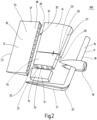
- Fig. 1 shows a perspective view of a rudder blade 100 with a modular structure.
- the rudder blade 100 has prefabricated rudder blade segments 10, 11, 12, 13 and is composed of the rudder blade segments 10, 11, 12, 13.
- a first rudder blade segment 10 is designed as a main section 14.
- a second rudder blade segment 11 is designed as a front rudder blade section 15.
- a third rudder blade segment is designed as a rear rudder blade section 16.
- a fourth rudder blade segment 13 is designed as an intermediate section 17.
- the front rudder blade section 15 comprises a leading edge 18 and a propulsion bulb 19.
- the second rudder blade segment 11, or the front rudder blade section 15, is approximately L-shaped, with a rudder blade sole section 21 adjoining the lower region 20.
- the rudder blade sole section 21 is aligned approximately at a right angle to the section of the second rudder blade segment 11 on which the leading edge 18 is arranged and merges into this section via a radius 22.
- the rudder blade sole section 21 can be formed integrally with the second rudder blade segment 11, which represents the front rudder blade section 15. However, it is also possible for the rudder blade sole section 21 to be an independent rudder blade segment.
- the third rudder blade segment 12 has a trailing edge 23.
- the outer walls 24 of the rear rudder blade section 16, or the third rudder blade section 12, are flat.
- the fourth rudder blade segment designed as an intermediate section 17 and also referred to as a "semi-flat piece," has substantially slightly curved outer walls 25.
- the first rudder blade segment 10, the second rudder blade segment 11, and the third rudder blade segment 12 enclose the intermediate section 17 and the fourth rudder blade segment 13, respectively.
- the illustrated rudder 100 is a twisted rudder. This means that the upper section 26a of the leading edge 18 is offset relative to a lower section 26b of the leading edge 18, so that the upper section 26a is offset toward port, while the lower section 26b is offset toward starboard.
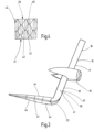
- Fig. 2 shows an exploded view of the rudder 100 with a modular structure.
- the second rudder blade segment 11, which is designed as a front rudder blade section 15, comprises the leading edge 18, the propulsion bulb 19 and the rudder blade sole section 21.
- the first rudder blade segment 10, designed as the main section 14, is composed of a first sub-segment 27 and a second sub-segment 28.
- the first sub-segment 27 and the second sub-segment 28 are connected to one another via a connecting body 30 designed as a stabilizing plate 29.
- a longitudinal frame 32 is visible on an underside 31 of the second sub-segment 28 of the main section 14.
- the main section 14, or the rudder blade segment composed of the first sub-segment 27 and the second sub-segment 28 The first rudder blade segment 10 is manufactured in a conventional manufacturing process by planking a skeleton structure 33 formed from longitudinal frames 32 and transverse frames with an outer wall 34.
- the second rudder blade segment 11, which forms the front rudder blade section 15, is manufactured using an additive or generative manufacturing process, in particular a 3D printing process.
- the third rudder blade segment 12, designed as a rear rudder blade section 16 has a solid steel honeycomb structural element 36 in an interior space 35, so that the third rudder blade segment 12 is designed as a lightweight structural element 37.
- the fourth rudder blade segment 13, designed as an intermediate section 17, can be manufactured using a conventional manufacturing process by planking a skeleton structure, using a 3D printing process, or using other methods.
- the materials of the rudder blade segments 10, 11, 12, and 13 also vary.
- the second rudder blade segment 11, manufactured using a 3D printing process can be made of plastic or metal.
- the main section 14, manufactured using a known manufacturing process is made of steel.
- the rear rudder blade section 16 can also be manufactured using a conventional or known manufacturing process. However, it is also possible for the rear rudder blade section 16 to be made of or comprise a plastic.
- Fig. 3 shows the second rudder blade segment 11, designed as the front rudder blade section 15, in a perspective view.
- the second rudder blade segment 11 has a structured surface 39.
- the leading edge 18 is provided with the structured surface 39.
- the structured surface 39 has bionic structures 40.
- the bionic structures 40 can be designed, for example, as a sharkskin structure 41.
- FIG. 4 A section of the structured surface 39 of the leading edge 18 is shown.
- the bionic structure 40 comprising a shark skin structure 41, has several elevations 42.
- the structured surface 39 or the bionic structure 40 of the leading edge 18 of the second rudder blade segment 11 is advantageously produced simultaneously in the same manufacturing step as the second rudder blade segment 11 using a generative, additive, or 3D printing process.
- the bionic structures 40 therefore do not have to be subsequently machined from the second rudder blade segment 11, for example, by means of a milling process.
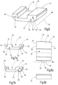
- Fig. 5 shows the main section 14 in a perspective view.
- the main section 14 is composed of a first sub-segment 27 and a second sub-segment 28, which are connected to each other via a stabilizing plate 29.
- a skeleton structure 33 consisting of longitudinal frames 32 and transverse frames 43, which is provided with an outer wall 34.
- the rudder blade sole section 21 of the second rudder blade segment 11 is also composed of several sub-segments 44.
- a sub-segment 44 of the rudder blade sole section 21 is shown in a perspective view in Fig. 6
- the sub-segment 44 of the rudder blade sole section 21 is approximately U-shaped and has a recess or groove 45 extending in a longitudinal direction 46 of the sub-segment 44.
- the groove 45 is not arranged centrally, but rather slightly offset within the sub-segment 44.
- a first end face 47 of the sub-segment 44 has connecting means 49 configured as receiving openings 48.
- the subsegment 44 is shown in a front view ( Fig. 7a ) and in a rear view ( Fig. 7b ).
- the front view shows a second end face 50 of the sub-segment 44.
- Connecting means 52 also designed as receiving openings 51, are located in the second end face 50.
- Fig. 7b In the rear view shown, the connecting means 49 are again shown in the first end face 47.
- Snap-in hooks or click-in connecting elements (not shown) or screws, if necessary, can then be guided into the receiving openings 48, 51, and thus a plurality of sub-segments 44 can be connected to one another to form a rudder blade sole section 21.
- the sub-segment 44 is also manufactured using a 3D printing process as part of the second rudder blade segment 11.
- the material is preferably PET-G or ABS.
- the course of a first side 54 is more curved than the course of a second side 55 opposite the first side 54.
- the different course corresponds to the different course of the sides of the rudder blade 100, which is designed as a twisted rudder and thus has a pressure side 56 and a suction side 57.
Landscapes
- Chemical & Material Sciences (AREA)
- Engineering & Computer Science (AREA)
- Mechanical Engineering (AREA)
- Combustion & Propulsion (AREA)
- Ocean & Marine Engineering (AREA)
- Materials Engineering (AREA)
- Manufacturing & Machinery (AREA)
- Physics & Mathematics (AREA)
- Fluid Mechanics (AREA)
- Optics & Photonics (AREA)
Priority Applications (8)
| Application Number | Priority Date | Filing Date | Title |
|---|---|---|---|
| PL17204181.6T PL3489128T3 (pl) | 2017-11-28 | 2017-11-28 | Płetwa sterowa o budowie modułowej, segment do płetwy sterowej lub urządzenia do usprawnienia napędu i sposób wytwarzania płetwy sterowej |
| EP17204181.6A EP3489128B1 (de) | 2017-11-28 | 2017-11-28 | Ruderblatt mit modularem aufbau, segment für ein ruderblatt oder für eine vorrichtung zur propulsionsverbesserung und verfahren zur herstellung eines ruderblatts |
| CA3025112A CA3025112A1 (en) | 2017-11-28 | 2018-11-23 | Rudder blade with a modular structure, segment for a rudder blade or for an apparatus for improving propulsion and method for manufacturing a rudder blade |
| TW107142069A TW201925028A (zh) | 2017-11-28 | 2018-11-26 | 具有模組化結構的舵葉、用於舵葉或用於改進推進的設備的區段以及用於製造舵葉的方法 |
| JP2018219869A JP7272782B2 (ja) | 2017-11-28 | 2018-11-26 | モジュール構造を有する舵板、舵板のためのまたは推進を改善する装置のためのセグメント、および舵板を製造する方法 |
| US16/201,667 US20190161151A1 (en) | 2017-11-28 | 2018-11-27 | Rudder blade with a modular structure, segment for a rudder blade or for an apparatus for improving propulsion and method for manufacturing a rudder blade |
| KR1020180149746A KR102618746B1 (ko) | 2017-11-28 | 2018-11-28 | 모듈식 구조를 갖는 러더 블레이드, 추진력을 향상시키기 위한 장치 또는 러더 블레이드용 세그먼트, 및 러더 블레이드의 제조방법 |
| CN201811436887.3A CN110001912B (zh) | 2017-11-28 | 2018-11-28 | 舵叶及其制造方法 |
Applications Claiming Priority (1)
| Application Number | Priority Date | Filing Date | Title |
|---|---|---|---|
| EP17204181.6A EP3489128B1 (de) | 2017-11-28 | 2017-11-28 | Ruderblatt mit modularem aufbau, segment für ein ruderblatt oder für eine vorrichtung zur propulsionsverbesserung und verfahren zur herstellung eines ruderblatts |
Publications (2)
| Publication Number | Publication Date |
|---|---|
| EP3489128A1 EP3489128A1 (de) | 2019-05-29 |
| EP3489128B1 true EP3489128B1 (de) | 2025-06-04 |
Family
ID=60484220
Family Applications (1)
| Application Number | Title | Priority Date | Filing Date |
|---|---|---|---|
| EP17204181.6A Active EP3489128B1 (de) | 2017-11-28 | 2017-11-28 | Ruderblatt mit modularem aufbau, segment für ein ruderblatt oder für eine vorrichtung zur propulsionsverbesserung und verfahren zur herstellung eines ruderblatts |
Country Status (8)
| Country | Link |
|---|---|
| US (1) | US20190161151A1 (enExample) |
| EP (1) | EP3489128B1 (enExample) |
| JP (1) | JP7272782B2 (enExample) |
| KR (1) | KR102618746B1 (enExample) |
| CN (1) | CN110001912B (enExample) |
| CA (1) | CA3025112A1 (enExample) |
| PL (1) | PL3489128T3 (enExample) |
| TW (1) | TW201925028A (enExample) |
Families Citing this family (11)
| Publication number | Priority date | Publication date | Assignee | Title |
|---|---|---|---|---|
| EP3489128B1 (de) * | 2017-11-28 | 2025-06-04 | Becker Marine Systems GmbH | Ruderblatt mit modularem aufbau, segment für ein ruderblatt oder für eine vorrichtung zur propulsionsverbesserung und verfahren zur herstellung eines ruderblatts |
| EP3778237A1 (en) * | 2019-08-14 | 2021-02-17 | ABB Schweiz AG | Combined additive and substractive manufacturing of bladed rotors |
| CN110723263B (zh) * | 2019-09-17 | 2020-07-14 | 广州文冲船舶修造有限公司 | 一种船舶舵叶改装工艺 |
| CN110877693B (zh) * | 2019-11-15 | 2022-04-01 | 沪东中华造船(集团)有限公司 | 一种lng船双层底分段的智能制造方法 |
| CN111661275B (zh) * | 2020-05-29 | 2021-06-08 | 广州文冲船舶修造有限公司 | 一种舵杆换新工艺 |
| CN113799388B (zh) * | 2021-08-19 | 2025-02-11 | 共享智能装备有限公司 | 打印头的安装装置及3d打印设备 |
| CN113561056A (zh) * | 2021-08-26 | 2021-10-29 | 无锡市东舟船舶设备股份有限公司 | 一种用于舵杆和舵叶拂配的工装 |
| CN116101449A (zh) * | 2022-09-29 | 2023-05-12 | 沪东中华造船(集团)有限公司 | 一种舵叶进舵辅助装置及进舵方法 |
| US20240190078A1 (en) * | 2022-12-08 | 2024-06-13 | GM Global Technology Operations LLC | System and method for locating and joining part sections enabled by additive manufacturing |
| CN115946821B (zh) * | 2022-12-20 | 2025-09-12 | 招商局金陵船舶(南京)有限公司 | 一种船舶半悬挂式扭曲舵叶制作安装方法 |
| CN115675832B (zh) * | 2022-12-27 | 2023-03-17 | 成都航空职业技术学院 | 一种多段式空间四边形机翼骨架及仿生飞行器 |
Citations (3)
| Publication number | Priority date | Publication date | Assignee | Title |
|---|---|---|---|---|
| FR1128161A (fr) * | 1955-06-28 | 1957-01-03 | Dispositif pour le démontage de l'arbre d'hélice dans les bateaux et applications analogues | |
| JPH0314793A (ja) * | 1989-06-12 | 1991-01-23 | Japan Hamuwaaji Kk | 船舶用舵の組立方法 |
| US20160319668A1 (en) * | 2015-04-28 | 2016-11-03 | The Boeing Company | Textured leading edge for aerospace and nautical structures |
Family Cites Families (34)
| Publication number | Priority date | Publication date | Assignee | Title |
|---|---|---|---|---|
| US3710749A (en) * | 1971-02-08 | 1973-01-16 | C Duryea | Boat flanking rudder system |
| DE2555098C2 (de) * | 1975-12-08 | 1977-10-13 | Willi Becker Ingenieurbüro, 2000 Hamburg | Ruder, insbesondere Balance-Profilruder mit einer Flosse, für Wasserfahrzeuge |
| DE3041661A1 (de) * | 1980-11-05 | 1982-06-16 | Willi Becker Ingenieurbüro GmbH, 2000 Hamburg | Ruder fuer wasserfahrzeuge, insbesondere fuer hochsee- und binnenschiffe, und fuer schwimmendes geraet |
| JPH037695A (ja) * | 1989-06-05 | 1991-01-14 | Japan Hamuwaaji Kk | 船舶用舵およびその製作方法 |
| JPH0546698U (ja) * | 1991-11-28 | 1993-06-22 | 川崎重工業株式会社 | 舶用フラップラダー |
| JPH0632290A (ja) * | 1992-07-13 | 1994-02-08 | Hitachi Zosen Corp | 船舶における舵 |
| FR2693701B1 (fr) * | 1992-07-16 | 1994-09-02 | France Etat Armement | Safrans pour navires de moyen et gros tonnage. |
| JP2888759B2 (ja) * | 1994-07-19 | 1999-05-10 | 日本操舵システム株式会社 | マリーナ型シリング舵 |
| JP2000302099A (ja) | 1999-04-23 | 2000-10-31 | Yamaha Motor Co Ltd | 小型船舶の舵板構造 |
| US20050076819A1 (en) * | 2002-10-10 | 2005-04-14 | Hilleman Terry Bruceman | Apparatus and method for reducing hydrofoil cavitation |
| KR100648367B1 (ko) | 2005-11-21 | 2006-11-23 | 현대중공업 주식회사 | 침식방지용 압력평형 구조의 선박용 방향타 |
| KR200410384Y1 (ko) * | 2005-12-21 | 2006-03-08 | 삼성중공업 주식회사 | 스페이드 러더 |
| JP4936798B2 (ja) | 2006-06-09 | 2012-05-23 | ジャパン・ハムワージ株式会社 | マリナー型高揚力二枚舵装置 |
| US7931240B2 (en) | 2006-08-11 | 2011-04-26 | Techno-Sciences, Inc. | Cellular support structures used for controlled actuation of fluid contact surfaces |
| DE202006017370U1 (de) * | 2006-11-13 | 2008-03-20 | Becker Marine Systems Gmbh & Co. Kg | Ruder für Schiffe |
| DE202007008804U1 (de) * | 2007-06-21 | 2007-08-16 | Becker Marine Systems Gmbh & Co. Kg | Ruder für ein Schiff |
| DE102008005253A1 (de) * | 2007-08-02 | 2009-07-23 | Benz, Gerhard, Dipl.-Ing. | Segel-Yacht mit einem krängenden und einem nicht krängenden Bootsrumpf-Teilkörper, insbesondere kombinierbares Segel-Yacht- und Motorboot-Modulsystem |
| ES2341393T3 (es) * | 2007-11-13 | 2010-06-18 | BECKER MARINE SYSTEMS GMBH & CO. KG | Dispositivo de timon para embarcaciones de gran velocidad, en especial timon completamente suspendido reductor de cavitacion, alabeado. |
| DE202007016164U1 (de) * | 2007-11-16 | 2008-01-24 | Becker Marine Systems Gmbh & Co. Kg | Hochleistungsruder für Schiffe |
| KR20100122537A (ko) * | 2009-05-13 | 2010-11-23 | 최정관 | 자석 성분을 함유하는 한방재 조성물 |
| CN101913250A (zh) * | 2010-08-17 | 2010-12-15 | 沈阳飞机工业(集团)有限公司 | 方向舵壁板成型工艺 |
| US9359054B2 (en) * | 2010-11-30 | 2016-06-07 | Thomas W Watts | Control mechanism |
| JP5689328B2 (ja) | 2011-02-03 | 2015-03-25 | 住友重機械マリンエンジニアリング株式会社 | ラダーバルブ付き舵、船舶、及びラダーバルブ、並びにラダーバルブ付き舵の製造方法 |
| KR101324964B1 (ko) * | 2011-02-25 | 2013-11-04 | 삼성중공업 주식회사 | 선박용 러더 |
| US9205904B2 (en) | 2011-05-04 | 2015-12-08 | Massachusetts Institute Of Technology | Multi-axis water jet propulsion using Coanda effect valves |
| KR101267897B1 (ko) * | 2011-08-24 | 2013-05-27 | 대우조선해양 주식회사 | 선박용 러더의 표면층 구조 및 그 형성 방법 |
| KR101122537B1 (ko) | 2011-09-23 | 2012-03-23 | (주)지엠코 | 선박용 방향타 |
| DE102014101120A1 (de) * | 2013-01-30 | 2014-07-31 | Becker Marine Systems Gmbh & Co. Kg | Hohlstruktur und Herstellungsverfahren für eine Hohlstruktur |
| NO336848B1 (no) | 2013-03-08 | 2015-11-16 | Rolls Royce Marine As Rudders | Roranordning |
| DE102014217228A1 (de) * | 2014-08-28 | 2016-03-03 | Skf Blohm + Voss Industries Gmbh | Flossenstabilisator, Verfahren und Wasserfahrzeug |
| CN105599889B (zh) * | 2016-01-12 | 2019-12-27 | 中国人民解放军海军工程大学 | 一种高刚度轻质实芯复合材料舵叶 |
| JP2017177885A (ja) * | 2016-03-28 | 2017-10-05 | 三菱重工業株式会社 | 舵板 |
| US10660310B2 (en) | 2017-09-26 | 2020-05-26 | William Bright | Pet grooming tool |
| EP3489128B1 (de) * | 2017-11-28 | 2025-06-04 | Becker Marine Systems GmbH | Ruderblatt mit modularem aufbau, segment für ein ruderblatt oder für eine vorrichtung zur propulsionsverbesserung und verfahren zur herstellung eines ruderblatts |
-
2017
- 2017-11-28 EP EP17204181.6A patent/EP3489128B1/de active Active
- 2017-11-28 PL PL17204181.6T patent/PL3489128T3/pl unknown
-
2018
- 2018-11-23 CA CA3025112A patent/CA3025112A1/en not_active Abandoned
- 2018-11-26 JP JP2018219869A patent/JP7272782B2/ja active Active
- 2018-11-26 TW TW107142069A patent/TW201925028A/zh unknown
- 2018-11-27 US US16/201,667 patent/US20190161151A1/en not_active Abandoned
- 2018-11-28 CN CN201811436887.3A patent/CN110001912B/zh active Active
- 2018-11-28 KR KR1020180149746A patent/KR102618746B1/ko active Active
Patent Citations (3)
| Publication number | Priority date | Publication date | Assignee | Title |
|---|---|---|---|---|
| FR1128161A (fr) * | 1955-06-28 | 1957-01-03 | Dispositif pour le démontage de l'arbre d'hélice dans les bateaux et applications analogues | |
| JPH0314793A (ja) * | 1989-06-12 | 1991-01-23 | Japan Hamuwaaji Kk | 船舶用舵の組立方法 |
| US20160319668A1 (en) * | 2015-04-28 | 2016-11-03 | The Boeing Company | Textured leading edge for aerospace and nautical structures |
Also Published As
| Publication number | Publication date |
|---|---|
| PL3489128T3 (pl) | 2025-08-04 |
| CA3025112A1 (en) | 2019-05-28 |
| JP7272782B2 (ja) | 2023-05-12 |
| EP3489128A1 (de) | 2019-05-29 |
| CN110001912B (zh) | 2023-03-28 |
| US20190161151A1 (en) | 2019-05-30 |
| KR20190062315A (ko) | 2019-06-05 |
| JP2019099143A (ja) | 2019-06-24 |
| CN110001912A (zh) | 2019-07-12 |
| TW201925028A (zh) | 2019-07-01 |
| KR102618746B1 (ko) | 2023-12-27 |
Similar Documents
| Publication | Publication Date | Title |
|---|---|---|
| EP3489128B1 (de) | Ruderblatt mit modularem aufbau, segment für ein ruderblatt oder für eine vorrichtung zur propulsionsverbesserung und verfahren zur herstellung eines ruderblatts | |
| EP2060484B2 (de) | Ruder für Schiffe | |
| EP1921005B1 (de) | Ruder für Schiffe | |
| EP3064427B1 (de) | Anordnung für mehrschraubenschiffe mit aussenliegenden propellerwellen sowie verfahren zur herstellung einer solchen anordnung | |
| EP2060485B1 (de) | Ruderanordnung für Schiffe mit höheren Geschwindigkeiten mit einem kavitationsreduzierenden, twistierten, insbesondere Vollschweberuder | |
| EP2025593B1 (de) | Ruder für Schiffe | |
| EP2277772B1 (de) | Düsenpropeller für Schiffe | |
| DE3332868A1 (de) | Bootsschraubenantriebseinheit | |
| DE3885105T2 (de) | Kombinierte ruder- und schraubenanordnung. | |
| EP2161194B1 (de) | Motorischer Propellerantrieb für ein Wasserfahrzeug | |
| EP2154064A1 (de) | Ruderanordnung für Schiffe mit höheren Geschwindigkeiten mit einem kavitationsreduzierenden, twistierten, insbesondere Vollschweberuder | |
| WO2003070567A1 (de) | Linienentwurf und propulsionsanordnung für ein kursstabiles, seegehendes schiff mit ruderpropellerantrieb | |
| EP3544887B1 (de) | Düse eines schiffspropellers | |
| EP1508516A1 (de) | Kompaktes wasserstrahlantriebs und -lenksystem | |
| EP2676876A2 (de) | Unterseeboot | |
| DE202017107215U1 (de) | Ruderblatt mit modularem Aufbau, Segment für ein Ruderblatt oder für eine Vorrichtung zur Propulsionsverbesserung | |
| DE10018573A1 (de) | Wasserfahrzeug | |
| EP3782901A1 (de) | Ruder und verfahren zur herstellung eines ruders | |
| DE663286C (de) | Wasserfahrzeug mit Antrieb durch Schraube und Duese | |
| DE651579C (de) | Wasserfahrzeug | |
| DE2246766C3 (de) | Steuereinrichtung für Schiffe | |
| DE10054148A1 (de) | Schiff, insbesondere schnelles Fährschiff mit PoD-Antrieb | |
| DE2848370C2 (de) | Kortdüse mit seitlich erweiterter Wassereinströmöffnung | |
| EP3464045B1 (de) | Wasserfahrzeug, insbesondere schleppschiff | |
| EP1787904A2 (de) | Hochlast-Schweberuder |
Legal Events
| Date | Code | Title | Description |
|---|---|---|---|
| PUAI | Public reference made under article 153(3) epc to a published international application that has entered the european phase |
Free format text: ORIGINAL CODE: 0009012 |
|
| STAA | Information on the status of an ep patent application or granted ep patent |
Free format text: STATUS: THE APPLICATION HAS BEEN PUBLISHED |
|
| AK | Designated contracting states |
Kind code of ref document: A1 Designated state(s): AL AT BE BG CH CY CZ DE DK EE ES FI FR GB GR HR HU IE IS IT LI LT LU LV MC MK MT NL NO PL PT RO RS SE SI SK SM TR |
|
| AX | Request for extension of the european patent |
Extension state: BA ME |
|
| STAA | Information on the status of an ep patent application or granted ep patent |
Free format text: STATUS: REQUEST FOR EXAMINATION WAS MADE |
|
| 17P | Request for examination filed |
Effective date: 20190829 |
|
| RBV | Designated contracting states (corrected) |
Designated state(s): AL AT BE BG CH CY CZ DE DK EE ES FI FR GB GR HR HU IE IS IT LI LT LU LV MC MK MT NL NO PL PT RO RS SE SI SK SM TR |
|
| STAA | Information on the status of an ep patent application or granted ep patent |
Free format text: STATUS: EXAMINATION IS IN PROGRESS |
|
| 17Q | First examination report despatched |
Effective date: 20191127 |
|
| P01 | Opt-out of the competence of the unified patent court (upc) registered |
Effective date: 20230529 |
|
| GRAP | Despatch of communication of intention to grant a patent |
Free format text: ORIGINAL CODE: EPIDOSNIGR1 |
|
| STAA | Information on the status of an ep patent application or granted ep patent |
Free format text: STATUS: GRANT OF PATENT IS INTENDED |
|
| INTG | Intention to grant announced |
Effective date: 20250102 |
|
| GRAS | Grant fee paid |
Free format text: ORIGINAL CODE: EPIDOSNIGR3 |
|
| GRAA | (expected) grant |
Free format text: ORIGINAL CODE: 0009210 |
|
| STAA | Information on the status of an ep patent application or granted ep patent |
Free format text: STATUS: THE PATENT HAS BEEN GRANTED |
|
| AK | Designated contracting states |
Kind code of ref document: B1 Designated state(s): AL AT BE BG CH CY CZ DE DK EE ES FI FR GB GR HR HU IE IS IT LI LT LU LV MC MK MT NL NO PL PT RO RS SE SI SK SM TR |
|
| REG | Reference to a national code |
Ref country code: GB Ref legal event code: FG4D Free format text: NOT ENGLISH |
|
| REG | Reference to a national code |
Ref country code: CH Ref legal event code: EP |
|
| REG | Reference to a national code |
Ref country code: DE Ref legal event code: R096 Ref document number: 502017016872 Country of ref document: DE |
|
| REG | Reference to a national code |
Ref country code: IE Ref legal event code: FG4D Free format text: LANGUAGE OF EP DOCUMENT: GERMAN |
|
| REG | Reference to a national code |
Ref country code: NL Ref legal event code: FP |
|
| PG25 | Lapsed in a contracting state [announced via postgrant information from national office to epo] |
Ref country code: ES Free format text: LAPSE BECAUSE OF FAILURE TO SUBMIT A TRANSLATION OF THE DESCRIPTION OR TO PAY THE FEE WITHIN THE PRESCRIBED TIME-LIMIT Effective date: 20250604 Ref country code: FI Free format text: LAPSE BECAUSE OF FAILURE TO SUBMIT A TRANSLATION OF THE DESCRIPTION OR TO PAY THE FEE WITHIN THE PRESCRIBED TIME-LIMIT Effective date: 20250604 |
|
| REG | Reference to a national code |
Ref country code: LT Ref legal event code: MG9D |
|
| PG25 | Lapsed in a contracting state [announced via postgrant information from national office to epo] |
Ref country code: NO Free format text: LAPSE BECAUSE OF FAILURE TO SUBMIT A TRANSLATION OF THE DESCRIPTION OR TO PAY THE FEE WITHIN THE PRESCRIBED TIME-LIMIT Effective date: 20250904 Ref country code: GR Free format text: LAPSE BECAUSE OF FAILURE TO SUBMIT A TRANSLATION OF THE DESCRIPTION OR TO PAY THE FEE WITHIN THE PRESCRIBED TIME-LIMIT Effective date: 20250905 |
|
| PG25 | Lapsed in a contracting state [announced via postgrant information from national office to epo] |
Ref country code: BG Free format text: LAPSE BECAUSE OF FAILURE TO SUBMIT A TRANSLATION OF THE DESCRIPTION OR TO PAY THE FEE WITHIN THE PRESCRIBED TIME-LIMIT Effective date: 20250604 |
|
| PG25 | Lapsed in a contracting state [announced via postgrant information from national office to epo] |
Ref country code: HR Free format text: LAPSE BECAUSE OF FAILURE TO SUBMIT A TRANSLATION OF THE DESCRIPTION OR TO PAY THE FEE WITHIN THE PRESCRIBED TIME-LIMIT Effective date: 20250604 |
|
| PG25 | Lapsed in a contracting state [announced via postgrant information from national office to epo] |
Ref country code: RS Free format text: LAPSE BECAUSE OF FAILURE TO SUBMIT A TRANSLATION OF THE DESCRIPTION OR TO PAY THE FEE WITHIN THE PRESCRIBED TIME-LIMIT Effective date: 20250904 |
|
| PG25 | Lapsed in a contracting state [announced via postgrant information from national office to epo] |
Ref country code: LV Free format text: LAPSE BECAUSE OF FAILURE TO SUBMIT A TRANSLATION OF THE DESCRIPTION OR TO PAY THE FEE WITHIN THE PRESCRIBED TIME-LIMIT Effective date: 20250604 |
|
| PG25 | Lapsed in a contracting state [announced via postgrant information from national office to epo] |
Ref country code: PT Free format text: LAPSE BECAUSE OF FAILURE TO SUBMIT A TRANSLATION OF THE DESCRIPTION OR TO PAY THE FEE WITHIN THE PRESCRIBED TIME-LIMIT Effective date: 20251006 |