EP3489037A1 - Reifen - Google Patents
Reifen Download PDFInfo
- Publication number
- EP3489037A1 EP3489037A1 EP18205297.7A EP18205297A EP3489037A1 EP 3489037 A1 EP3489037 A1 EP 3489037A1 EP 18205297 A EP18205297 A EP 18205297A EP 3489037 A1 EP3489037 A1 EP 3489037A1
- Authority
- EP
- European Patent Office
- Prior art keywords
- crown
- main groove
- sipes
- tyre
- land region
- Prior art date
- Legal status (The legal status is an assumption and is not a legal conclusion. Google has not performed a legal analysis and makes no representation as to the accuracy of the status listed.)
- Granted
Links
- 238000012360 testing method Methods 0.000 description 22
- 230000004043 responsiveness Effects 0.000 description 17
- 230000000052 comparative effect Effects 0.000 description 6
- 230000007423 decrease Effects 0.000 description 6
- 230000003247 decreasing effect Effects 0.000 description 5
- 238000011156 evaluation Methods 0.000 description 4
- 238000000926 separation method Methods 0.000 description 4
- 238000010998 test method Methods 0.000 description 4
- 238000006073 displacement reaction Methods 0.000 description 3
- 230000000694 effects Effects 0.000 description 3
- 238000011161 development Methods 0.000 description 2
- 238000013461 design Methods 0.000 description 1
- 238000002474 experimental method Methods 0.000 description 1
- 238000005086 pumping Methods 0.000 description 1
- 230000004044 response Effects 0.000 description 1
- XLYOFNOQVPJJNP-UHFFFAOYSA-N water Substances O XLYOFNOQVPJJNP-UHFFFAOYSA-N 0.000 description 1
Images


Classifications
-
- B—PERFORMING OPERATIONS; TRANSPORTING
- B60—VEHICLES IN GENERAL
- B60C—VEHICLE TYRES; TYRE INFLATION; TYRE CHANGING; CONNECTING VALVES TO INFLATABLE ELASTIC BODIES IN GENERAL; DEVICES OR ARRANGEMENTS RELATED TO TYRES
- B60C11/00—Tyre tread bands; Tread patterns; Anti-skid inserts
- B60C11/03—Tread patterns
- B60C11/0302—Tread patterns directional pattern, i.e. with main rolling direction
-
- B—PERFORMING OPERATIONS; TRANSPORTING
- B60—VEHICLES IN GENERAL
- B60C—VEHICLE TYRES; TYRE INFLATION; TYRE CHANGING; CONNECTING VALVES TO INFLATABLE ELASTIC BODIES IN GENERAL; DEVICES OR ARRANGEMENTS RELATED TO TYRES
- B60C11/00—Tyre tread bands; Tread patterns; Anti-skid inserts
- B60C11/03—Tread patterns
- B60C11/0304—Asymmetric patterns
-
- B—PERFORMING OPERATIONS; TRANSPORTING
- B60—VEHICLES IN GENERAL
- B60C—VEHICLE TYRES; TYRE INFLATION; TYRE CHANGING; CONNECTING VALVES TO INFLATABLE ELASTIC BODIES IN GENERAL; DEVICES OR ARRANGEMENTS RELATED TO TYRES
- B60C11/00—Tyre tread bands; Tread patterns; Anti-skid inserts
- B60C11/03—Tread patterns
- B60C11/0306—Patterns comprising block rows or discontinuous ribs
-
- B—PERFORMING OPERATIONS; TRANSPORTING
- B60—VEHICLES IN GENERAL
- B60C—VEHICLE TYRES; TYRE INFLATION; TYRE CHANGING; CONNECTING VALVES TO INFLATABLE ELASTIC BODIES IN GENERAL; DEVICES OR ARRANGEMENTS RELATED TO TYRES
- B60C11/00—Tyre tread bands; Tread patterns; Anti-skid inserts
- B60C11/03—Tread patterns
- B60C11/12—Tread patterns characterised by the use of narrow slits or incisions, e.g. sipes
- B60C11/1204—Tread patterns characterised by the use of narrow slits or incisions, e.g. sipes with special shape of the sipe
-
- B—PERFORMING OPERATIONS; TRANSPORTING
- B60—VEHICLES IN GENERAL
- B60C—VEHICLE TYRES; TYRE INFLATION; TYRE CHANGING; CONNECTING VALVES TO INFLATABLE ELASTIC BODIES IN GENERAL; DEVICES OR ARRANGEMENTS RELATED TO TYRES
- B60C11/00—Tyre tread bands; Tread patterns; Anti-skid inserts
- B60C11/03—Tread patterns
- B60C11/12—Tread patterns characterised by the use of narrow slits or incisions, e.g. sipes
- B60C11/1236—Tread patterns characterised by the use of narrow slits or incisions, e.g. sipes with special arrangements in the tread pattern
-
- B—PERFORMING OPERATIONS; TRANSPORTING
- B60—VEHICLES IN GENERAL
- B60C—VEHICLE TYRES; TYRE INFLATION; TYRE CHANGING; CONNECTING VALVES TO INFLATABLE ELASTIC BODIES IN GENERAL; DEVICES OR ARRANGEMENTS RELATED TO TYRES
- B60C11/00—Tyre tread bands; Tread patterns; Anti-skid inserts
- B60C11/03—Tread patterns
- B60C11/12—Tread patterns characterised by the use of narrow slits or incisions, e.g. sipes
- B60C11/1259—Depth of the sipe
- B60C11/1263—Depth of the sipe different within the same sipe
-
- B—PERFORMING OPERATIONS; TRANSPORTING
- B60—VEHICLES IN GENERAL
- B60C—VEHICLE TYRES; TYRE INFLATION; TYRE CHANGING; CONNECTING VALVES TO INFLATABLE ELASTIC BODIES IN GENERAL; DEVICES OR ARRANGEMENTS RELATED TO TYRES
- B60C11/00—Tyre tread bands; Tread patterns; Anti-skid inserts
- B60C11/03—Tread patterns
- B60C11/12—Tread patterns characterised by the use of narrow slits or incisions, e.g. sipes
- B60C11/1272—Width of the sipe
- B60C11/1281—Width of the sipe different within the same sipe, i.e. enlarged width portion at sipe bottom or along its length
-
- B—PERFORMING OPERATIONS; TRANSPORTING
- B60—VEHICLES IN GENERAL
- B60C—VEHICLE TYRES; TYRE INFLATION; TYRE CHANGING; CONNECTING VALVES TO INFLATABLE ELASTIC BODIES IN GENERAL; DEVICES OR ARRANGEMENTS RELATED TO TYRES
- B60C11/00—Tyre tread bands; Tread patterns; Anti-skid inserts
- B60C11/03—Tread patterns
- B60C2011/0337—Tread patterns characterised by particular design features of the pattern
- B60C2011/0339—Grooves
- B60C2011/0341—Circumferential grooves
- B60C2011/0355—Circumferential grooves characterised by depth
-
- B—PERFORMING OPERATIONS; TRANSPORTING
- B60—VEHICLES IN GENERAL
- B60C—VEHICLE TYRES; TYRE INFLATION; TYRE CHANGING; CONNECTING VALVES TO INFLATABLE ELASTIC BODIES IN GENERAL; DEVICES OR ARRANGEMENTS RELATED TO TYRES
- B60C11/00—Tyre tread bands; Tread patterns; Anti-skid inserts
- B60C11/03—Tread patterns
- B60C2011/0337—Tread patterns characterised by particular design features of the pattern
- B60C2011/0339—Grooves
- B60C2011/0358—Lateral grooves, i.e. having an angle of 45 to 90 degees to the equatorial plane
-
- B—PERFORMING OPERATIONS; TRANSPORTING
- B60—VEHICLES IN GENERAL
- B60C—VEHICLE TYRES; TYRE INFLATION; TYRE CHANGING; CONNECTING VALVES TO INFLATABLE ELASTIC BODIES IN GENERAL; DEVICES OR ARRANGEMENTS RELATED TO TYRES
- B60C11/00—Tyre tread bands; Tread patterns; Anti-skid inserts
- B60C11/03—Tread patterns
- B60C2011/0337—Tread patterns characterised by particular design features of the pattern
- B60C2011/0386—Continuous ribs
- B60C2011/0388—Continuous ribs provided at the equatorial plane
-
- B—PERFORMING OPERATIONS; TRANSPORTING
- B60—VEHICLES IN GENERAL
- B60C—VEHICLE TYRES; TYRE INFLATION; TYRE CHANGING; CONNECTING VALVES TO INFLATABLE ELASTIC BODIES IN GENERAL; DEVICES OR ARRANGEMENTS RELATED TO TYRES
- B60C11/00—Tyre tread bands; Tread patterns; Anti-skid inserts
- B60C11/03—Tread patterns
- B60C11/12—Tread patterns characterised by the use of narrow slits or incisions, e.g. sipes
- B60C11/1236—Tread patterns characterised by the use of narrow slits or incisions, e.g. sipes with special arrangements in the tread pattern
- B60C2011/1254—Tread patterns characterised by the use of narrow slits or incisions, e.g. sipes with special arrangements in the tread pattern with closed sipe, i.e. not extending to a groove
-
- B—PERFORMING OPERATIONS; TRANSPORTING
- B60—VEHICLES IN GENERAL
- B60C—VEHICLE TYRES; TYRE INFLATION; TYRE CHANGING; CONNECTING VALVES TO INFLATABLE ELASTIC BODIES IN GENERAL; DEVICES OR ARRANGEMENTS RELATED TO TYRES
- B60C11/00—Tyre tread bands; Tread patterns; Anti-skid inserts
- B60C11/03—Tread patterns
- B60C11/12—Tread patterns characterised by the use of narrow slits or incisions, e.g. sipes
- B60C11/1259—Depth of the sipe
- B60C2011/1268—Depth of the sipe being different from sipe to sipe
-
- B—PERFORMING OPERATIONS; TRANSPORTING
- B60—VEHICLES IN GENERAL
- B60C—VEHICLE TYRES; TYRE INFLATION; TYRE CHANGING; CONNECTING VALVES TO INFLATABLE ELASTIC BODIES IN GENERAL; DEVICES OR ARRANGEMENTS RELATED TO TYRES
- B60C11/00—Tyre tread bands; Tread patterns; Anti-skid inserts
- B60C11/03—Tread patterns
- B60C11/12—Tread patterns characterised by the use of narrow slits or incisions, e.g. sipes
- B60C11/1272—Width of the sipe
- B60C2011/1286—Width of the sipe being different from sipe to sipe
Definitions
- the present invention relates to a tyre provided with a crown sipe.
- Japanese unexamined Patent Application Publication No. 2016-13820 has proposed providing a shoulder sipe extending in a tyre axial direction in a shoulder land region of a pneumatic tyre in order to suppress uneven wear of the shoulder land region.
- the present invention was made in view of the above, and a primary object thereof is to provide a tyre capable of exerting excellent steering stability while suppressing the uneven wear of the crown land region.
- a tyre comprises a tread portion whose position when mounted on a vehicle is specified and having an asymmetric pattern with respect to a tyre equator, wherein the tread portion comprises an outer shoulder main groove extending continuously in a tyre circumferential direction, an outer crown main groove extending adjacently to the outer shoulder main groove and continuously in the tyre circumferential direction, an inner crown main groove extending adjacently to the outer crown main groove and continuously in the tyre circumferential direction, an outer crown land region defined between the outer shoulder main groove and the outer crown main groove, and a center crown land region defined between the outer crown main groove and the inner crown main groove, the outer crown land region is provided with first outer crown sipes each completely crossing the outer crown land region and second outer crown sipes each extending from the outer crown main groove toward the outer shoulder main groove and terminating within the outer crown land region, the center crown land region is provided with first center crown sipes each completely crossing the center crown land region, and second center crown si
- the tread portion further comprises an inner shoulder main groove extending adjacently to the inner crown main groove and continuously in the tyre circumferential direction, and an inner crown land region defined between the inner shoulder main groove and the inner crown main groove, the inner crown land region is provided with a plurality of crown lateral grooves each extending from the inner shoulder main groove toward the inner crown main groove with a width of not less than 1.5 mm and having an inner end terminating within the inner crown land region and first inner crown sipes each extending between the inner end of a respective one of the crown lateral grooves and the inner crown main groove with a width of less than 1.5 mm, and each of the first inner crown sipes is arranged so as to be smoothly continuous with a respective one of the second center crown sipes with the inner crown main groove therebetween.
- the inner crown land region is provided with a plurality of second inner crown sipes each extending from the inner shoulder main groove toward the inner crown main groove with a width of less than 1.5 mm and having an inner end terminating within the inner crown land region.
- a length in a tyre axial direction of each of the crown lateral grooves is larger than a length in the tyre axial direction of each of the second inner crown sipes.
- the inner crown land region is provided with a plurality of third inner crown sipes each extending from the inner crown main groove toward the inner shoulder main groove with a width of less than 1.5 mm and having an outer end terminating within the inner crown land region.
- each of the third inner crown sipes is arranged so as to be smoothly continuous with a respective one of the first center crown sipes with the inner crown main groove therebetween.
- each of the third inner crown sipes is curved so as to be convex toward on side in the tyre circumferential direction, and each of the first center crown sipes is curved so as to be convex toward the other side in the tyre circumferential direction.
- each of the third inner crown sipes is curved with a radius of curvature smaller than that of each of the first center crown sipes.
- each of the first inner crown sipes is curved so as to be convex toward one side in the tyre circumferential direction
- each of the second center crown sipes is curved so as to be convex toward the other side in the tyre circumferential direction.
- each of the first inner crown sipes is curved with a radius of curvature smaller than that of each of the second center crown sipes.
- a portion between at least one of sipe walls thereof and a tread ground contacting surface is chamfered so that a width thereof gradually increases toward the outer crown main groove.
- a portion between at least one of sipe walls thereof and the tread ground contacting surface is chamfered so that a width thereof gradually increases toward the outer crown main groove.
- each of the first outer crown sipe with the outer crown main groove one of sipe walls thereof on one side in the tyre circumferential direction is chamfered, and in a connecting portion of each of the first center crown sipes with the outer crown main groove, one of sipe walls thereof on the other side in the tyre circumferential direction is chamfered.
- a portion between at least one of sipe walls thereof and the tread ground contacting surface is chamfered so that a width thereof gradually increases toward the inner crown main groove.
- each of the first outer crown sipes includes a narrow sipe portion and a wide sipe portion having a width larger than that of the narrow sipe portion.
- the wide sipe portion is connected with the outer shoulder main groove.
- a length in the tyre axial direction of the narrow sipe portion is larger than a length in the tyre axial direction of the wide sipe portion.
- a depth of the wide sipe portion is larger than a depth of the narrow sipe portion.
- each of the second outer crown sipes includes a first sipe portion and a second sipe portion having a depth smaller than that of the first sipe portion.
- each of the second center crown sipes terminates within the center crown land region without crossing the tyre equator.
- the tyre comprises the tread portion whose position when mounted on a vehicle is specified and having the asymmetric pattern with respect to the tyre equator.
- the tread portion of one aspect of the present invention comprises the outer shoulder main groove extending continuously in the tyre circumferential direction, the outer crown main groove extending adjacently to the outer shoulder main groove and continuously in the tyre circumferential direction, the inner crown main groove extending adjacently to the outer crown main groove and continuously in the tyre circumferential direction, the outer crown land region defined between the outer shoulder main groove and the outer crown main groove, and the center crown land region defined between the outer crown main groove and the inner crown main groove.
- the center crown land region of the tyre of one aspect of the present invention is provided with the first center crown sipes each completely crossing the center crown land region, and the second center crown sipes each extending from the inner crown main groove toward the outer crown main groove and terminating within the center crown land region,
- the center crown land region configured as such exerts the same effects as the outer crown land region described above, therefore, it is possible that the steering stability is improved.
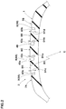
- Fig. 1 is a development view of a tread portion 2 of a tyre 1 showing an embodiment of the present invention.
- the tyre 1 in this embodiment can be used for various tyres such as a pneumatic tyre for a passenger car and for heavy load, and a non-pneumatic tyre not filled with pressurized air therein, for example.
- the tyre 1 in this embodiment is suitably used as a pneumatic tyre for a passenger car, for example.
- the tyre 1 in this embodiment has the tread portion 2 whose position when mounted on a vehicle is specified and having an asymmetric pattern with respect to the tyre equator.
- the tread portion 2 has a first tread edge (Te1) located, when the tyre 1 is mounted on a vehicle, on an outer side of the vehicle and a second tread edge (Te2) located on an inner side of the vehicle when the tyre is mounted on the vehicle, for example.
- the mounting position of the tyre 1 on a vehicle is indicated by a letter or a symbol on one of sidewall portions (not shown), for example.
- the tread edges (Te1) and (Te2) are defined as outermost ground contacting positions in a tyre axial direction of the tyre 1 when the tyre 1 in a standard state is in contact with a flat surface with zero camber angle by being loaded with a standard tyre load.
- the standard state is a state in which the tyre is mounted on a standard rim, inflated to a standard inner pressure, and loaded with no tyre load.
- dimensions and the like of various parts of the tyre are values measured in the standard state.
- the "standard rim” is a wheel rim specified for the concerned tyre by a standard included in a standardization system on which the tyre is based, for example, the "normal wheel rim” in JATMA, "Design Rim” in TRA, and “Measuring Rim” in ETRTO.
- the "standard pressure” is air pressure specified for the concerned tyre by a standard included in a standardization system on which the tyre is based, for example, the “maximum air pressure” in JATMA, maximum value listed in the "TIRE LOAD LIMITS AT VARIOUS COLD INFLATION PRESSURES" table in TRA, and "INFLATION PRESSURE” in ETRTO.
- the "standard load” is a tyre load specified for the concerned tyre by a standard included in a standardization system on which the tyre is based, for example, the "maximum load capacity" in JATMA, maximum value listed in “TIRE LOAD LIMITS AT VARIOUS COLD INFLATION PRESSURES" table in TRA, and "LOAD CAPACITY" in ETRTO.
- main grooves extending continuously in a tyre circumferential direction are provided, for example.
- the main grooves include a shoulder main groove 3 provided between the first tread edge (Te1) and a tyre equator (C) or between the second tread edge (Te2) and the tyre equator (C), and a crown main groove 4 arranged adjacently to the shoulder main groove 3, for example.
- the shoulder main groove 3 in this embodiment includes an outer shoulder main groove 3A provided between the first tread edge (Te1) and the tyre equator (C), and an inner shoulder main groove 3B provided between the second tread edge (Te2) and the tyre equator (C), for example.
- each of the shoulder main grooves 3 is arranged so that a distance (L1a) between a groove center line thereof and the tyre equator (C) is in the range of from 0.20 to 0.30 times a tread width TW, for example.
- the tread width TW is a distance in the tyre axial direction in the standard state between the first tread edge (Te1) and the second tread edge (Te2).
- the crown main groove 4 includes an outer crown main groove 4A and an inner crown main groove 4B.
- the outer crown main groove 4A is provided between the tyre equator (C) and the outer shoulder main groove 3A.
- the inner crown main groove 4B is provided between the tyre equator (C) and the inner shoulder main groove 3B.
- the crown main groove 4 is formed such that a distance (L1b) from a groove center line thereof and the tyre equator (C) is in the range of from 0.05 to 0.15 times the tread width TW, for example.
- each of a groove width (W1a) of the outer crown main groove 4A and a groove width (W1b) of the inner crown main groove 4B is larger than each of a groove width (W1c) of the outer shoulder main groove 3A and a groove width (W1d) of the inner shoulder main groove 3B, for example.
- each of the groove width (W1a) of the outer crown main groove 4A and the groove width (W1b) of the inner crown main groove 4B is in the range of from 1.25 to 1.35 times the groove width (W1b) of the outer shoulder main groove 3A.
- the groove width (W1d) of the inner shoulder main groove 3B is greater than the groove width (W1c) of the outer shoulder main groove 3A, for example. Specifically, it is preferred that the groove width (W1d) of the inner shoulder main groove 3B is in the range of from 1.20 to 1.28 times the groove width (W1c) of the outer shoulder main groove 3A.
- the groove width (W1a) of the outer crown main groove 4A, the groove width (W1b) of the inner crown main groove 4B, and the groove width (W1c) of the outer shoulder main groove 3A and the groove width (W1d) of the inner shoulder main groove 3B are each in the range of from 2.5% to 5.0% of the tread width TW, for example. Note that when dimensions of the grooves are shown in this specification, the dimensions not including chamfers are shown.
- Fig. 2 is a cross-sectional view taken along A-A line of Fig. 1 .
- a groove depth (D1a) of the outer crown main groove 4A, a groove depth (D1b) of the inner crown main groove 4B, a groove depth (D1c) of the outer shoulder main groove 3A and a groove depth (D1d) of the inner shoulder main groove 3B are in the range of from 6.0 to 12.0 mm, for example.
- the tread portion 2 in this embodiment is divided by the main grooves described above into an outer shoulder land region 7A, an inner shoulder land region 7B, an outer crown land region 8A, an inner crown land region 8B, and a center crown land region 8C.
- the outer shoulder land region 7A is defined between the first tread edge (Te1) and the outer shoulder main groove 3A.
- the inner shoulder land region 7B is defined between the second tread edge (Te2) and the inner shoulder main groove 3B.
- the outer crown land region 8A is defined between the outer shoulder main groove 3A and the outer crown main groove 4A.
- the inner crown land region 8B is defined between the inner shoulder main groove 3B and the inner crown main groove 4B.
- the center crown land region 8C is defined between the outer crown main groove 4A and the inner crown main groove 4B.
- Fig. 3 is an enlarged view of the outer crown land region 8A and the center crown land region 8C.
- outer crown land region 8A is provided with first outer crown sipes 26 and second outer crown sipes 27.
- the term "sipe” means a groove having a width of less than 1.5 mm.
- Each of the first outer crown sipes 26 completely crosses the outer crown land region 8A.
- Each of the second outer crown sipes 27 extends from the outer crown main groove 4A toward the outer shoulder main groove 3A and terminates within the outer crown land region 8A.
- the first outer crown sipes 26 and the second outer crown sipes 27 moderate deformation of the outer crown land region 8A at the time of contacting the ground, therefore, the uneven wear thereof is suppressed.
- the second outer crown sipes 27 together with the first outer crown sipes 26 further moderate the rigidity of a part on the side of the outer crown main groove 4A of the outer crown land region 8A. Therefore, it is made easy for the outer crown land region 8A to follow the road surface even in an early stage of cornering in which the ground contact pressure is not sufficiently increased, for example, thereby, excellent initial responsiveness is obtained eventually.
- the second outer crown sipes 27 terminate within the outer crown land region 8A, therefore, the outer crown land region 8A has high rigidity in a part thereof on the side of the outer shoulder main groove 3A.
- the outer crown land region 8A exerts large cornering force in a middle stage of cornering when sufficient ground contacting load is applied to the tyre, for example, therefore, it is possible that the steering stability is improved eventually.
- the center crown land region 8C is provided with first center crown sipes 45 and second center crown sipes 46. Each of the first center crown sipes 45 completely crosses the center crown land region 8C. Each of the second center crown sipes 46 extends from the inner crown main groove 4B toward the outer crown main groove 4A and terminates within the center crown land region 8C.
- the first center crown sipes 45 and the second center crown sipes 46 moderate deformation of the center crown land region 8C at the time of contacting the ground, therefore, the uneven wear thereof is suppressed. Further, the second center crown sipes 46 together with the first center crown sipes 45 further moderate the rigidity of a part on the side of the inner crown main groove 4B of the center crown land region 8C. Thereby, it is made easy for the center crown land region 8C to follow the road surface even in an early stage of cornering in which the ground contact pressure is not sufficiently increased, for example, therefore, excellent initial responsiveness is obtained eventually.
- the second center crown sipes 46 terminate within the center crown land region 8C, therefore, the center crown land region 8C has high rigidity in a part thereof on the side of the outer shoulder main groove 3A.
- the center crown land region 8C exerts large cornering force in the middle stage of cornering when sufficient ground contacting load is applied to the tyre, for example, therefore, it is possible that the steering stability is improved eventually.
- Fig. 4 is an enlarged view of one of the second outer crown sipes 27 and the first center crown sipes 45.
- each of the second outer crown sipes 27 is arranged at a position so as to be smoothly continuous with a respective one of the first center crown sipes 45 with the outer crown main groove 4A therebetween.
- the sipe being "provided at a position so as to be smoothly continuous" with another sipe at least includes an embodiment in which a minimum separation distance in the tyre circumferential direction between a first region (32a) obtained by virtually extending one of the sipes and a second region (32b) obtained by virtually extending the other one of the sipes is less than 1.0 mm.
- first region (32a) intersects with an end portion of the other one of the sipes and the second region (32b) intersects with an end portion of the one of the sipes.
- the rigidity is moderated in a part on the side of the outer crown main groove 4A of each of the outer crown land region 8A and the center crown land region 8C, thereby, it is possible that further excellent initial responsiveness is obtained.
- each of the first outer crown sipes 26 includes a narrow sipe portion 22 and a wide sipe portion 23 having a width larger than that of the narrow sipe portion 22, for example.
- the wide sipe portion 23 is connected with the outer shoulder main groove 3A, for example.
- the narrow sipe portion 22 has the width in the range of from 0.4 to 0.8 mm, for example.
- the width of the wide sipe portion 23 is preferably in the range of from 1.50 to 1.80 times, more preferably in the range of from 1.60 to 1.70 times the width of the narrow sipe portion 22, and specifically, preferably in the range of from 0.8 to 1.2 mm, for example.
- the wide sipe portion 23 can moderate the rigidity of a surrounding land part more than the narrow sipe portion 22.
- variation of the ground contacting load during running is larger in a part on a side of the outer shoulder main groove 3A than in a part on a side of the outer crown main groove 4A, therefore, uneven wear is more likely to occur due to minute slippage of the ground contacting surface.
- by providing the wide sipe portions 23 in this region it is made easy for the surrounding land parts to follow the road surface, therefore, it is possible that the minute slippage is suppressed, thereby, it is possible that the uneven wear of the outer crown land region 8A is eventually further suppressed.
- the land parts around the wide sipe portions 23 are likely to follow the road surface even in a state of early stage of cornering in which the ground contacting load is not sufficiently increased, for example, therefore, it is possible that the initial responsiveness is increased as well.
- the land parts around the narrow sipe portions 22 provide higher rigidity than the land parts around the wide sipe portions 23, therefore, large cornering force is exerted, thereby, it is possible that the steering stability is eventually improved.
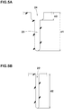
- Fig. 5A is a cross-sectional view of one of the wide sipe portions 23 taken along B-B line of Fig. 3 .
- Fig. 5B is a cross-sectional view of one of the narrow sipe portions 22 taken along C-C line of Fig. 3 .
- a depth (d1) of each of the wide sipe portions 23 is larger than a depth (d2) of each of the narrow sipe portions 22.
- the depth (d1) of each of the wide sipe portions 23 is preferably not less than 1.03 times, more preferably not less than 1.06 times, and preferably not more than 1.15 times, more preferably not more than 1.12 times the depth (d2) of each of the narrow sipe portions 22.
- the depths (d1) and (d2) each correspond to a distance along a depth direction of the sipe between a ground contacting surface of the land region and a bottom of the sipe, for example.
- the outer crown land region 8A is provided with narrow groove portions 24 each having a groove width of not less than 1.5 mm and a groove depth of not more than 2.0 mm, and that the wide sipe portion 23 extends inwardly in a tyre radial direction from a groove bottom of each of the narrow groove portions 24.
- a depth (d3) of each of the narrow groove portions 24 is in the range of from 1.0 to 2.0 mm, for example. It is possible that the narrow groove portions 24 and the wide sipe portions 23 configured as such further improve the uneven wear resistance performance.
- each of the narrow groove portions 24 with the outer shoulder main groove 3A a portion between at least one of groove walls thereof and the tread ground contacting surface is chamfered so that the groove width thereof gradually increases toward the outer shoulder main groove 3A.
- Each of the narrow groove portions 24 provided in the outer crown land region 8A has a chamfered portion 25 provided in one of the groove walls thereof.
- a length L9 in the tyre axial direction of each of the wide sipe portions 23 is in the range of from 0.30 to 0.40 times a width W7 of the outer crown land region 8A, for example.
- Each of the narrow sipe portions 22 is connected with the outer crown main groove 4A, for example. It is preferred that a length L10 in the tyre axial direction of each of the narrow sipe portions 22 is greater than the length L9 in the tyre axial direction of each of the wide sipe portions 23.
- the length L10 of each of the narrow sipe portions 22 is in the range of from 1.60 to 1.80 times the length L9 of each of the wide sipe portions 23, for example. with the wide sipe portions 23 and the narrow sipe portions 22 configured as such, it is possible that large cornering force is obtained while excellent initial responsiveness is exerted.
- a portion between at least one of sipe walls and the tread ground contacting surface is chamfered so that a width thereof gradually increases toward the outer crown main groove 4A.
- a chamfered portion 28 is provided on the sipe wall on the opposite side (the lower side in Fig. 3 ) to the chamfered portion 25 provided on the groove wall of each of the narrow groove portions 24.
- the chamfered portions 28 configured as such decrease air column resonance sound of the outer crown main groove 4A, therefore, it is possible that noise performance is eventually improved.
- Fig. 6A is a cross-sectional view of one of the first outer crown sipes 26 taken along E-E line of Fig. 3 .
- each of the first outer crown sipes 26 includes a first sipe portion (26a) arranged on a side of the outer shoulder main groove 3A and a second sipe portion (26b) arranged on a side of the outer crown main groove 4A, for example.
- the second sipe portion (26b) has a smaller depth than the first sipe portion (26a), for example.
- a depth (d5) of the second sipe portion (26b) is in the range of from 0.45 to 0.55 times a depth (d4) of the first sipe portion (26a), for example.
- the first outer crown sipes 26 configured as such maintain the rigidity of a portion of the outer crown land region 8A on a side of the tyre equator (C) while improving the initial responsiveness, therefore, it is possible that further excellent steering stability is exerted.
- a length L11 in the tyre axial direction of each of the second outer crown sipes 27 is in the range of from 0.35 to 0.55 times, preferably in the range of from 0.42 to 0.48 times the width w7 in the tyre axial direction of the outer crown land region 8A, for example. Further, it is preferred that terminating ends 29 of the second outer crown sipes 27 are located closer to the crown main groove 4 than end portions on the side of the crown main groove 4 of the wide sipe portions 23 of the first outer crown sipes 26.
- the second outer crown sipes 27 configured as such suppress excessive decrease in the rigidity of the outer crown land region 8A, therefore, it is possible that large cornering force is provided.
- each of the second outer crown sipes 27 is curved so as to be convex toward either side in the tyre circumferential direction, for example. It is preferred that a radius of curvature of each of the second outer crown sipes 27 is in the range of from 70 to 90 mm, for example.
- Fig. 6B is a cross-sectional view of one of the second outer crown sipes 27 taken along F-F line orthogonal thereto of Fig. 3 .
- each of the second outer crown sipes 27 has an opening portion 30 having a width increasing outwardly in the tyre radial direction, for example.
- one of sipe walls 31 on one side in the tyre circumferential direction of each of the second outer crown sipes 27 is inclined, whereby the opening portion 30 is formed.
- the sipe walls 31 on both sides may be inclined in each of the second outer crown sipes 27, for example.
- the second outer crown sipes 27 may be respectively provided at the groove bottoms of the narrow groove portions described above, for example.
- Fig. 6C is a cross-sectional view taken along G-G line along one of the second outer crown sipes 27 of Fig. 3 .
- each of the second outer crown sipes 27 includes a first sipe portion (27a) arranged on a side of the terminating end 29 and a second sipe portion (27b) arranged on the side of the outer crown main groove 4A.
- the second sipe portion (27b) has a smaller depth than the first sipe portion (27a), for example. It is preferred that a depth (d7) of the second sipe portion (27b) is in the range of from 0.45 to 0.55 times a depth (d6) of the first sipe portion (27a), for example.
- Each of the second outer crown sipes 27 configured as such suppresses a portion thereof on the side of the outer crown main groove 4A from being excessively opened, therefore, it is possible that the uneven wear resistance performance and the steering stability are improved.
- the first center crown sipes 45 are inclined with respect to the tyre axial direction. It is preferred that an angle ⁇ 3 of each of the first center crown sipes 45 with respect to the tyre axial direction is in the range of from 10 to 30 degrees, for example.
- each of the first center crown sipes 45 is curved so as to be convex toward either side in the tyre circumferential direction, for example.
- the first center crown sipes 45 in this embodiment are convex toward the same direction as the second outer crown sipes 27, for example.
- a radius of curvature of each of the first center crown sipes 45 is larger than a radius of curvature of each of the second outer crown sipes 27, for example.
- the radius of curvature of each of the first center crown sipes 45 is in the range of from 140 to 160 mm, for example.
- the first center crown sipes 45 configured as such are helpful for suppressing the uneven wear of the center crown land region 8C.
- each of the first center crown sipes 45 with the outer crown main groove 4A a portion between at least one of sipe walls and the tread ground contacting surface is chamfered so that the width thereof gradually increases toward the outer crown main groove 4A.
- a portion between at least one of sipe walls and the tread ground contacting surface is chamfered so that the width thereof gradually increases toward the inner crown main groove 4B.
- a chamfered portion 48 provided on the side of the inner crown main groove 4B is arranged on the opposite side in the tyre circumferential direction to a chamfered portion 47 provided on the side of the outer crown main groove 4A with respect to each of the first center crown sipes 45.
- each of the first outer crown sipes 26 with the outer crown main groove 4A one of the sipe walls thereof on one side (the lower side in Fig. 3 ) in the tyre circumferential direction is chamfered and in a connecting portion of each of the first center crown sipes 45 with the outer crown main groove 4A, one of the sipe walls thereof on the other side (the upper side in Fig. 3 ) in the tyre circumferential direction is chamfered.
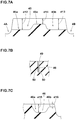
- Fig. 7A is a cross-sectional view of one of the first center crown sipes 45 taken along K-K line of Fig. 3 .
- each of the first center crown sipes 45 includes a first sipe portion (45a), arranged on a side of the outer crown main groove 4A, a second sipe portion (45b) arranged on a side of the inner crown main groove 4B, and a third sipe portion (45c) arranged between the first sipe portion (45a) and the second sipe portion (45b).
- a depth (d12) of the first sipe portion (45a) and a depth (d13) of the second sipe portion (45b) are each in the range of from 0.60 to 0.75 times the groove depth (D1a) (shown in Fig. 2 ) of the outer crown main groove 4A, for example.
- the third sipe portion (45c) has a depth (d14) smaller than those of the first sipe portion (45a) and the second sipe portion (45b), for example.
- the depth (d14) of the third sipe portion (45c) is in the range of from 0.40 to 0.60 times the depth (d12) of the first sipe portion (45a), for example. It is possible that the first center crown sipes 45 configured as such improve the steering stability and the uneven wear resistance performance in a good balance.
- a length L17 in the tyre axial direction of each of the second center crown sipes 46 is in the range of from 0.40 to 0.60 times a width W8 in the tyre axial direction of the center crown land region 8C, for example.
- Each of the second center crown sipes 46 in this embodiment terminates within the land region without crossing the tyre equator (C), for example.
- each of the second center crown sipes 46 is curved so as to be convex toward either side in the tyre circumferential direction, for example. It is preferred that a radius of curvature of each of the second center crown sipes 46 is in the range of from 130 to 150 mm, for example.
- Fig. 7B is a cross-sectional view of one of the second center crown sipes 46 taken along L-L line orthogonal thereto of Fig. 3 .
- each of the second center crown sipes 46 has an opening portion 49 having a width increasing outwardly in the tyre radial direction, for example.
- one of sipe walls 50 on one side in the tyre circumferential direction of each of the second center crown sipes 46 is inclined, whereby the opening portion 49 is formed.
- the sipe walls 50 on both sides may be inclined in each of the second center crown sipes 46, for example.
- the second center crown sipes 46 may be respectively provided at the groove bottoms of the narrow groove portions described above, for example.
- the inclined sipe wall 31 is arranged on one side in the tyre circumferential direction (the lower side in Fig. 3 ) and in each of the second center crown sipes 46 in this embodiment, the inclined sipe wall 50 is arranged on the other side (the upper side in Fig. 3 ) in the tyre circumferential direction.
- Fig. 7C is a cross-sectional view taken along M-M line along one of the second center crown sipes 46 of Fig. 3 .
- each of the second center crown sipes 46 includes a first sipe portion (46a) arranged on a side of the terminating end thereof and a second sipe portion (46b) arranged on a side of the inner crown main groove 4B.
- the second sipe portion (46b) has a depth smaller than that of the first sipe portion (46a), for example. It is preferred that a depth (d16) of the second sipe portion (46b) is in the range of from 0.30 to 0.40 times a depth (d15) of the first sipe portion (46a), for example.
- Each of the second center crown sipes 46 configured as such suppresses a portion thereof on the side of the inner crown main groove 4B from being excessively opened, therefore, it is possible that the uneven wear resistance performance and the steering stability are improved.
- Fig. 8 is an enlarged view of the inner crown land region 8B in this embodiment.
- the inner crown land region 8B is provided with a plurality of crown lateral grooves 34 each having a width of not less than 1.5 mm and a plurality of inner crown sipes 35 each having a width of less than 1.5 mm.
- Each of the crown lateral grooves 34 extends from the inner shoulder main groove 3B toward the crown main groove 4 and has an inner end terminating within the inner crown land region 8B.
- the crown lateral grooves 34 cooperate with the inner shoulder main grooves 3B to improve drainage performance in the vicinity of the inner crown land region 8B, for example.
- the inner crown sipes 35 include first inner crown sipes 36, second inner crown sipes 37, and third inner crown sipes 38, for example.
- Each of the first inner crown sipes 36 extends between an inner end of a respective one of the crown lateral grooves 34 and the inner crown main groove 4B.
- Each of the second inner crown sipes 37 extends from the inner shoulder main groove 3B toward the crown main groove 4 and has an inner end terminating within the inner crown land region 8B.
- Each of the third inner crown sipes 38 extends from the inner crown main groove 4B toward the inner shoulder main groove 3B and has an outer end terminating within the inner crown land region 8B.
- the crown lateral grooves 34 and the first inner crown sipes 36 moderate deformation of the inner crown land region 8B at the time of contacting the ground, therefore, the uneven wear thereof is suppressed. Further, the crown lateral grooves 34 each having the width of not less than 1.5 mm further moderate the rigidity of the inner crown land region 8B in a part thereof on the side of the inner shoulder main groove 3B, therefore, it is made easy for the inner crown land region 8B to follow the road surface, thereby, excellent initial responsiveness is exerted.
- first inner crown sipes 36, the second inner crown sipes 37, and the third inner crown sipes 38 provide frictional force on a wet road surface by their respective edges. Furthermore, relatively large ground contact pressure is applied to the inner crown land region 8B, therefore, the wet performance is remarkably improved by the effect of these grooves and sipes.
- Each of the first inner crown sipes 36, the second inner crown sipes 37, and the third inner crown sipes 38 has a width of less than 1.5 mm, therefore, almost no pumping noise is generated at the time of contacting the ground. Further, the first inner crown sipes 36, the second inner crown sipes 37, and the third inner crown sipes 38 moderately moderate the rigidity of the inner crown land region 8B, therefore, it is possible that impact sound when the land region contacts the ground is decreased. Thereby, it is possible that excellent noise performance is obtained.
- each of the crown lateral grooves 34 is configured to have a length L12 in the tyre axial direction larger than a length L13 in the tyre axial direction of each of the second inner crown sipes 37.
- the length L12 of each of the crown lateral grooves 34 is preferably not less than 105%, more preferably not less than 108%, and preferably not more than 120%, more preferably not more than 114% of the length L13 in the tyre axial direction of each of the second inner crown sipes 37.
- the crown lateral grooves 34 are inclined with respect to the tyre axial direction, for example. It is preferred that a groove width of each of the crown lateral grooves 34 gradually decreases toward the inner crown main groove 4B, for example.
- a portion between at least one of groove walls thereof and the tread ground contacting surface is chamfered so that the groove width thereof gradually increases toward the inner shoulder main groove 3B, for example.
- a chamfered portion 39 is provided on one of the groove walls of each of the crown lateral grooves 34.
- the chamfered portion 39 of each of the crown lateral grooves 34 is provided on the same side in the tyre circumferential direction as the chamfered portion 28 (shown in Fig. 3 ) provided in the narrow sipe portion 22 of each of the first outer crown sipes 26. It is possible that the crown lateral grooves 34 configured as such suppress the generation of a stationary wave in the inner shoulder main groove 3B while improving the uneven wear resistance performance, therefore, it is possible that the air column resonance sound is eventually decreased.
- a length L14 in the tyre circumferential direction of the chamfered portion 39 of each of the crown lateral grooves 34 is in the range of from 0.15 to 0.30 times one pitch length P1 of the crown lateral grooves 34, for example.
- the first inner crown sipes 36 are inclined in the same direction as the crown lateral grooves 34, for example.
- one of edges of each of the first inner crown sipes 36 extends so as to be smoothly continuous with one of the edges on the same side of a respective one of the crown lateral grooves 34.
- a length L15 in the tyre axial direction of each of the first inner crown sipes 36 is in the range of from 0.50 to 0.65 times a width W9 in the tyre axial direction of the inner crown land region 8B, for example.
- each of the first inner crown sipes 36 is curved so as to be convex toward either side in the tyre circumferential direction, for example.
- Each of the first inner crown sipes 36 in this embodiment is curved so as to be convex toward the opposite side to each of the second center crown sipes 46 (shown in Fig. 3 ), for example.
- each of the first inner crown sipes 36 is curved so as to be convex toward one side in the tyre circumferential direction and each of the second center crown sipes 46 is curved so as to be convex toward the other side in the tyre circumferential direction.
- each of the first inner crown sipes 36 is curved with a radius of curvature smaller than that of each of the second center crown sipes 46, for example. It is preferred that the radius of curvature of each of the first inner crown sipes 36 is in the range of from 40 to 70 mm, for example.
- Fig. 9 is an enlarged view of the first inner crown sipes 36 and the second center crown sipes 46.
- each of the first inner crown sipes 36 is arranged at a position so as to be smoothly continuous with a respective one of the second center crown sipes 46 with the inner crown main groove 4B therebetween.
- the sipe being "provided at a position so as to be smoothly continuous" with another sipe at least includes, as described above, an embodiment in which the minimum separation distance in the tyre circumferential direction between the first region (32a) obtained by virtually extending one of the sipes and the second region (32b) obtained by virtually extending the other one of the sipes is less than 1.0 mm.
- first region (32a) intersects with an end portion of the other one of the sipes and the second region (32b) intersects with an end portion of the one of the sipes.
- each of the first inner crown sipes 36 has a chamfered portion 40 on the opposite side in the tyre circumferential direction to the chamfered portion 39 of each of the crown lateral grooves 34, for example.
- Fig. 10A is a cross-sectional view of one of the crown lateral grooves 34 and one of the first inner crown sipes 36 taken along H-H line of Fig. 8 .
- each of the first inner crown sipes 36 includes a first sipe portion (36a) arranged on a side of the crown main groove 4 and a second sipe portion (36b) arranged on a side of a respective one of the crown lateral grooves 34.
- the first sipe portion (36a) has a depth (d8) same as a depth (d17) of each of the crown lateral grooves 34, for example. It is preferred that the second sipe portion (36b) has a depth (d9) smaller than that of the first sipe portion (36a), for example.
- the depth (d9) of the second sipe portion (36b) is in the range of from 0.40 to 0.60 times the depth (d8) of the first sipe portion (36a), for example.
- the first inner crown sipes 36 configured as such make it easy for a part of the inner crown land region 8B on the side of the crown main groove 4 to deform moderately, therefore, it is possible that the generation of the stationary wave in the crown main groove 4 is suppressed, thereby, it is possible that the air column resonance sound of the crown main groove 4 is decreased.
- each of the second inner crown sipes 37 and the third inner crown sipes 38 terminates without crossing a center position in the tyre axial direction of the inner crown land region 8B.
- Each of the second inner crown sipes 37 and the third inner crown sipes 38 in this embodiment has a length in the tyre axial direction smaller than that of each of the first inner crown sipes 36, for example.
- the length L13 in the tyre axial direction of each of the second inner crown sipes 37 and a length L16 in the tyre axial direction of each of the third inner crown sipes 38 is in the range of from 0.60 to 0.75 times a length L15 in the tyre axial direction of each of the first inner crown sipes 36, respectively.
- the second inner crown sipes 37 and the third inner crown sipes 38 are inclined in the same direction as the first inner crown sipes 36 with respect to the tyre axial direction, for example. It is preferred that an angle ⁇ 1 of each of the second inner crown sipes 37 with respect to the tyre axial direction is in the range of from 0 to 20 degrees, for example. It is preferred that an angle ⁇ 2 of each of the third inner crown sipes 38 with respect to the tyre axial direction is larger than the angle ⁇ 1 and in the range of from 20 to 40 degrees, for example.
- the second inner crown sipes 37 and the third inner crown sipes 38 configured as such are useful for making the impact sound generated when the edges of each of the sipes contact the road surface into white noise.
- each of the second inner crown sipes 37 and the third inner crown sipes 38 is curved so as to be convex toward either side in the tyre circumferential direction, for example.
- the first inner crown sipes 36, the second inner crown sipes 37, and the third inner crown sipes 38 are convex toward the same direction with respect to the tyre circumferential direction.
- the radius of curvature of each of the second inner crown sipes 37 and the third inner crown sipes 38 is in the range of from 30 to 50 mm, for example.
- each of the third inner crown sipes 38 is curved so as to be convex toward the opposite direction to each of the first center crown sipes 45 (shown in Fig. 3 ), for example.
- each of the third inner crown sipes 38 is curved so as to be convex toward one side in the tyre circumferential direction and each of the first center crown sipes 45 is curved so as to be convex toward the other side in the tyre circumferential direction.
- each of the third inner crown sipes 38 is curved with the radius of curvature smaller than that of each of the first center crown sipes 45.
- each of the third inner crown sipes 38 is arranged at a position so as to be smoothly continuous with a respective one of the first center crown sipes 45 with the inner crown main groove 4B therebetween.
- Fig. 10B is a cross-sectional view of one of the second inner crown sipes 37 taken along I-I line perpendicular thereto of Fig. 8 .
- each of the second inner crown sipes 37 has an opening portion 41 having a width increasing outwardly in the tyre radial direction, for example.
- one of sipe walls 42 on one side in the tyre circumferential direction of each of the second inner crown sipes 37 is inclined, whereby the opening portion 41 is formed.
- One of the sipe walls 42 on the same side in the tyre circumferential direction as the inclined sipe wall 50 shown in Fig.
- each of the third inner crown sipes 38 has the same cross-sectional shape as each of the second inner crown sipes 37 described above, for example.
- Fig. 10C is a cross-sectional view of one of the second inner crown sipes 37 and one of the third inner crown sipes 38 taken along J-J line of Fig. 8 .
- each of the second inner crown sipes 37 extends at a constant depth until the depth gradually decreases near the inner end thereof.
- Each of the third inner crown sipes 38 includes a first sipe portion (38a) arranged on a side of a respective one of the second inner crown sipes 37 and a second sipe portion (38b) arranged on a side of the crown main groove 4.
- the first sipe portion (38a) has a depth (d10) same as a depth (d18) of each of the second inner crown sipes 37, for example.
- the second sipe portion (38b) has a depth (d11) smaller than that of the first sipe portion (38a), for example. It is preferred that the depth (d11) of the second sipe portion (38b) is in the range of from 0.45 to 0.55 times the depth (d10) of the first sipe portion (38a), for example. It is possible that the second inner crown sipes 37 and the third inner crown sipes 38 configured as such, in combination with the first inner crown sipes 36 described above, improve the wet performance and the noise performance in a good balance.
- each of the third inner crown sipes 38 is arranged so as to be smoothly continuous with a respective one of the first center crown sipes 45 with the inner crown main groove 4B therebetween.
- both of an inner edge (43a) arranged on the side of the inner crown main groove 4B and an outer edge (43b) arranged on the side of the inner shoulder main groove 3B of the inner crown land region 8B are chamfered. It is preferred that both of an inner edge (43a) arranged on the side of the outer crown main groove 4A and an outer edge (43b) arranged on the side of the outer shoulder main groove 3A of the outer crown land region 8A are chamfered. Similarly, it is preferred that each of edges (43c) of the center crown land region 8C is chamfered. It is possible that each of the land regions configured as such moderates the impact sound generated when the edges come into contact with the road surface.
- a radius of curvature R1 of the tread ground contacting surface is not more than 560 mm. Specifically, it is preferred that the radius of curvature R1 is in the range of from 400 to 500 mm.
- Fig. 11 is an enlarged view of the outer shoulder land region 7A as an example of the shoulder land region 7.
- the shoulder land region 7A is provided with shoulder sipes 10 extending in the tyre axial direction.
- the shoulder sipes provided in the outer shoulder land region 7A may be referred to as outer shoulder sipes.
- the shoulder sipes 10 moderate deformation of the shoulder land region 7A at the time of contacting the ground, therefore, the uneven wear thereof is suppressed.
- Each of the shoulder sipes 10 in this embodiment extends between the outer shoulder main groove 3A and the first tread edge (Te1). However, it is not limited to such an embodiment, and each of the shoulder sipes 10 may have one end or both ends terminating within the shoulder land region 7A.
- Each of the shoulder sipes 10 includes a narrow sipe portion 11 and a wide sipe portion 12 having a width larger than that of the narrow sipe portion 11. Note that the dimensions of the narrow sipe portion 22 and the wide sipe portion 23 of each of the first outer crown sipes 26 described above can be applied to the narrow sipe portion 11 and the wide sipe portion 12 of each of the shoulder sipes 10.
- the wide sipe portion 12 moderates the rigidity of the surrounding land part thereof more than the narrow sipe portion 11. Thereby, it is easy for the land part around the wide sipe portion 12 to follow the road surface even in an early stage of cornering in which the ground contacting load is not sufficiently increased, for example, therefore, it is possible that excellent initial responsiveness is obtained.
- the wide sipe portion 12 of the present invention is arranged on a side of the outer shoulder main groove 3A.
- a larger ground contacting load tends to be applied to a part of the outer shoulder land region 7A on a side of the outer shoulder main groove 3A than a part thereof on a side of the first tread edge (Te1) at the early stage of cornering. Therefore, by providing the wide sipe portions 12 in this region, the initial responsiveness is remarkably improved.
- the land parts around the narrow sipe portions 11 are located closer to the first tread edge (Te1) than the wide sipe portions 12, therefore, they provide higher rigidity than the land parts around the wide sipe portions 12, thereby, in the middle stage of cornering in which sufficient ground contacting load is applied to the tyre, for example, large cornering force is exerted, therefore, it is possible that the steering stability is improved eventually.
- each of the wide sipe portions 12 is connected with the outer shoulder main groove 3A, for example. It is preferred that a length L2 in the tyre axial direction of each of the wide sipe portions 12 is in the range of from 0.15 to 0.30 times a width W2 of the outer shoulder land region 7A, for example. It is possible that the wide sipe portions 12 configured as such improve uneven wear resistance performance and the steering stability in a good balance.
- each of the narrow sipe portions 11 is connected with the first tread edge (Te1), for example. Further, it is preferred that a length L3 in the tyre axial direction of each of the narrow sipe portions 11 is larger than the length L2 in the tyre axial direction of each of the wide sipe portions 12. Specifically, it is preferred that the length L3 of each of the narrow sipe portions 11 is in the range of from 3.0 to 4.5 times the length L2 of each of the wide sipe portions 12, for example.
- the outer shoulder land region 7A is provided with narrow groove portions 13 configured similarly to the narrow groove portions 24 (shown in Fig. 3 ) provided in the outer crown land region 8A, and that each of the wide sipe portions 12 extends inwardly in a tyre radial direction from a groove bottom of a respective one of the narrow groove portions 13. It is possible that the narrow groove portions 13 and the wide sipe portions 12 configured as such further improve the uneven wear resistance performance.
- each of the narrow groove portions 13 extends outwardly in the tyre axial direction from the outer shoulder main groove 3A and terminates between an outer end in the tyre axial direction of a respective one of the wide sipe portions 12 and the first tread edge (Te1), for example. It is preferred that a length L4 in the tyre axial direction of each of the narrow groove portions 13 is in the range of from 1.5 to 2.5 times the length L2 in the tyre axial direction of each of the wide sipe portions 12, for example.
- the narrow sipe portion 11 extends inwardly in the tyre radial direction from a groove bottom of the narrow groove portion 13. Further, in a region between the outer end of the narrow groove portion 13 and the first tread edge (Te1), it is preferred that the narrow sipe portion 11 extends with a constant width between a bottom thereof and the ground contacting surface.
- each of the narrow groove portions 13 with the outer shoulder main groove 3A, a portion between at least one of groove walls thereof and the tread ground contacting surface is chamfered so that a groove width thereof gradually increases toward the outer shoulder main groove 3A.
- only one of the groove walls has a chamfered portion 14, for example. It is possible that the narrow groove portions 13 configured as such decrease the air column resonance sound in the outer shoulder main groove 3A while improving the uneven wear resistance performance.
- each of the narrow groove portions 13 provided in the outer shoulder land region 7A has the chamfered portion 14 in the groove wall on one side (the lower side in Fig. 1 ) in the tyre circumferential direction
- each of the narrow groove portions 24 provided in the outer crown land region 8A has the chamfered portion 25 in the groove wall thereof on the other side (the upper side in Fig. 1 ) in the tyre circumferential direction.
- Each of the chamfered portions 25 provided in the outer crown land region 8A has a larger chamfer length in the tyre circumferential direction than that of each of the chamfered portions 14 provided in the outer shoulder land region 7A. It is possible that such an arrangement of the narrow groove portions 24 improves the uneven wear resistance performance and suppresses generation of a stationary wave in the outer shoulder main groove 3A, therefore, it is possible that the air column resonance sound is eventually decreased.
- each pair of one of the first outer crown sipes 26 and one of the outer shoulder sipes 10 adjacent to each other in the tyre axial direction it is preferred that a displacement amount in the tyre circumferential direction between the first outer crown sipe 26 and the outer shoulder sipe 10 at the outer shoulder main groove 3A is not more than 1.0 mm.
- Each of the outer shoulder sipes 10 in this embodiment is arranged so as to be continuous with a respective one of the first outer crown sipes 26 with the outer shoulder main groove 3A therebetween, and in a preferred embodiment, each of the outer shoulder sipes 10 includes a portion linearly continuous with a respective one of the first outer crown sipes 26 with the outer shoulder main groove 3A therebetween.
- the outer shoulder land region 7A in this embodiment is provided with a plurality of the outer shoulder sipes 10 arranged at intervals in the tyre circumferential direction, and a shoulder lateral groove 15 is arranged between each pair of the shoulder sipes 10 adjacent to each other in the tyre circumferential direction.
- the shoulder lateral grooves 15 provided in the outer shoulder land region 7A may be referred to as outer shoulder lateral grooves.
- Each of the shoulder lateral grooves 15 extends inwardly in the tyre axial direction from the first tread edge (Te1) and terminates without being connected with the outer shoulder main groove 3A, for example. It is possible that the shoulder lateral grooves 15 configured as such improve the wet performance while maintaining the rigidity of the outer shoulder land region 7A.
- inner ends (15a) in the tyre axial direction of the shoulder lateral grooves 15 are located on an outer side in the tyre axial direction of outer ends (12a) in the tyre axial direction of the wide sipe portions 12. It is preferred that a length L5 in the tyre axial direction of each of the shoulder lateral grooves 15 is in the range of from 0.60 to 0.75 times the width W2 in the tyre axial direction of the outer shoulder land region 7A, for example.
- a groove width W3 of each of the shoulder lateral grooves 15 is in the range of from 1.5 to 2.5 times a groove width w4 of each of the narrow groove portions 13, for example.
- Fig. 12 is an enlarged view of the inner shoulder land region 7B as another example of the shoulder land region 7.
- the inner shoulder land region 7B is provided with a plurality of inner shoulder lateral grooves 16, for example.
- Each of the inner shoulder lateral grooves 16 extends inwardly in the tyre axial direction from the second tread edge (Te2) and terminates without being connected with the inner shoulder main groove 3B, for example.
- a length L6 in the tyre axial direction of each of the inner shoulder lateral grooves 16 is in the range of from 0.70 to 0.80 times a width W5 in the tyre axial direction of the inner shoulder land region 7B, for example. It is possible that the inner shoulder lateral grooves 16 configured as such improve the steering stability and the wet performance in a good balance.
- a distance L7 in the tyre axial direction between an inner end of each of the inner shoulder lateral grooves 16 and the inner shoulder main groove 3B is smaller than a distance L8 (shown in Fig. 11 ) between an inner end of each of the outer shoulder lateral grooves 15 and the outer shoulder main groove 3A, for example.
- Each of the inner shoulder lateral grooves 16 has a groove width W6 larger than 2 mm, for example. It is preferred that the groove width W6 of each of the inner shoulder lateral grooves 16 is in the range of from 0.40 to 0.60 times the groove width (W1d) (shown in Fig. 1 ) of the inner shoulder main groove 3B, for example.
- each of the inner shoulder lateral grooves 16 is curved so as to be convex toward either side in the tyre circumferential direction, for example.
- the inner shoulder lateral grooves 16 in this embodiment are convex toward the same direction as the first inner crown sipes 36. It is preferred that a radius of curvature of each of the inner shoulder lateral grooves 16 is larger than the radius of curvature of each of the first inner crown sipes 36, for example. It is preferred that the radius of curvature of each of the inner shoulder lateral grooves 16 is in the range of from 80 to 100 mm, for example. It is possible that the inner shoulder lateral grooves 16 configured as such smoothly guide water in the grooves toward the second tread edge (Te2) during running on a wet road surface.
- the inner shoulder land region 7B is provided with connecting sipes 17 each extending so as to connect between a respective one of the inner shoulder lateral grooves 16 and the inner shoulder main groove 3B and inner shoulder sipes 18 each arranged between a respective pair of the inner shoulder lateral grooves 16 adjacent to each other in the tyre circumferential direction.
- Each of the connecting sipes 17 extends inwardly in the tyre radial direction from a groove bottom of a respective one of narrow groove portions 19 each having a groove width of not less than 1.5 mm and a groove depth of not more than 2.0 mm, for example.
- Each of the connecting sipes 17 has a width in the range of from 0.4 to 0.8 mm, for example. It is possible that dimensions of the narrow groove portions 13 provided in the outer shoulder land region 7A are applied to dimensions of the narrow groove portions 19, for example.
- each of the connecting sipes 17 is smoothly continuous with a respective one of the crown lateral grooves 34 with the inner shoulder main groove 3B therebetween.
- the crown lateral grooves 34 cooperate with the inner shoulder lateral grooves 16 to improve the wet performance.
- Fig. 13 is a cross-sectional view of one of the connecting sipes 17 taken along D-D line of Fig. 12 .
- each of the connecting sipes 17 includes a first sipe portion (17a) arranged on a side of a respective one of the inner shoulder lateral grooves 16 and a second sipe portion (17b) arranged on a side of the inner shoulder main groove 3B, for example.
- the second sipe portion (17b) has a depth smaller than that of the first sipe portion (17a), for example. It is preferred that a depth (d20) of the second sipe portion (17b) is in the range of from 0.35 to 0.55 times a depth (d19) of the first sipe portion (17a).
- Each of the connecting sipes 17 configured as such suppresses a portion thereof on the side of the inner shoulder main groove 3B from being excessively opened while improving the initial responsiveness, therefore, it is possible that the uneven wear resistance performance is improved as well.
- the inner shoulder sipes 18 extend along the inner shoulder lateral grooves 16, for example. Both ends of each of the inner shoulder sipes 18 terminate within the inner shoulder land region 7B, for example.
- the inner shoulder sipes 18 configured as such make it easier for the land region to follow the road surface while suppressing excessive decrease in the rigidity of the land region, therefore, it is possible that excellent steering stability and initial responsiveness are eventually exerted.
- each of the inner shoulder sipes 18 extends inwardly in the tyre radial direction from a groove bottom of a respective one of the narrow groove portions, for example.
- a land ratio (Lr1) of the region between the tyre equator (C) and the first tread edge (Te1) is larger than a land ratio (Lr2) of the region between the tyre equator (C) and the second tread edge (Te2).
- the land ratio (Lr1) is in the range of from 1.05 to 1.10 times the land ratio (Lr2).
- Tires of size 215/60R16 having the basic pattern shown in Fig. 1 were made by way of test according to the specifications listed in Table 1.
- tyres as shown in Fig. 14 were made by way of test.
- the second outer crown sipe (c) and the third inner crown sipe (d) are misaligned and not smoothly continuous with each other.
- the tyres as the Comparative Example had substantially the same tread portion as that shown in Fig. 1 except for the configurations described above.
- Each of the test tyres was tested for the steering stability and the uneven wear resistance performance of the crown land regions.
- Common specifications of the test tyres and the test methods are as follows.
- Tire rim 16x6.5J
- Tire inner pressure 250 kPa at front wheels, 230 kPa at rear wheels
- Test car 4WD-car with displacement of 1500 cc
- Tire mounting position all wheels
- test methods were as follows.
- the steering stability including the initial responsiveness was evaluated by the driver's feeling.
- the test results are indicated as an evaluation point based on the Comparative Example being 100 wherein the larger the numerical value, the better the steering stability is.
- Wear energy of the outer crown land region and the center crown land region was measured by using a wear energy measuring device.
- the test results are indicated by an index based on the wear energy of the Comparative Example being 100, wherein the smaller the numerical value, the smaller the wear energy is, which shows more excellent uneven wear resistance performance.
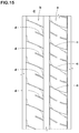
- Tires of size 215/60R16 having the basic pattern shown in Fig. 1 were made by way of test according to the specifications listed in Table 2.
- tyres as shown in Fig. 15 were made by way of test.
- the first inner crown sipe (c) and the second center crown sipe (d) are misaligned and not smoothly continuous with each other.
- the tyres as the Reference had substantially the same tread portion as that shown in Fig.
- test tyres were tested for the steering stability and the uneven wear resistance performance of the crown land regions.
- Common specifications of the test tyres and the test methods were as follows.
- Tire rim 16x6.0J
- Tire inner pressure 240 kPa
- Test car 4WD-car with displacement of 2000 cc
- Tire mounting position all wheels
- test methods were as follows.
- the steering stability including the initial responsiveness was evaluated by the driver's feeling.
- the test results are indicated as an evaluation point based on the Reference being 100 wherein the larger the numerical value, the better the steering stability is.
- the wear energy of the inner crown land region and the center crown land region was measured by using the wear energy measuring device.
- the test results are indicated by an index based on the wear energy of the Reference being 100, wherein the smaller the numerical value, the smaller the wear energy is, which shows more excellent uneven wear resistance performance.
Landscapes
- Engineering & Computer Science (AREA)
- Mechanical Engineering (AREA)
- Tires In General (AREA)
Applications Claiming Priority (2)
| Application Number | Priority Date | Filing Date | Title |
|---|---|---|---|
| JP2017226868A JP6943155B2 (ja) | 2017-11-27 | 2017-11-27 | タイヤ |
| JP2017247298A JP6927023B2 (ja) | 2017-12-25 | 2017-12-25 | タイヤ |
Publications (2)
| Publication Number | Publication Date |
|---|---|
| EP3489037A1 true EP3489037A1 (de) | 2019-05-29 |
| EP3489037B1 EP3489037B1 (de) | 2020-08-26 |
Family
ID=64270650
Family Applications (1)
| Application Number | Title | Priority Date | Filing Date |
|---|---|---|---|
| EP18205297.7A Active EP3489037B1 (de) | 2017-11-27 | 2018-11-09 | Reifen |
Country Status (3)
| Country | Link |
|---|---|
| US (1) | US11167596B2 (de) |
| EP (1) | EP3489037B1 (de) |
| CN (1) | CN109968914B (de) |
Cited By (1)
| Publication number | Priority date | Publication date | Assignee | Title |
|---|---|---|---|---|
| EP3785939A1 (de) * | 2019-08-30 | 2021-03-03 | Sumitomo Rubber Industries, Ltd. | Reifen |
Families Citing this family (7)
| Publication number | Priority date | Publication date | Assignee | Title |
|---|---|---|---|---|
| JP7275834B2 (ja) * | 2019-05-14 | 2023-05-18 | 住友ゴム工業株式会社 | タイヤ |
| CN112810387B (zh) * | 2019-11-18 | 2023-10-17 | 住友橡胶工业株式会社 | 轮胎 |
| JP7074120B2 (ja) * | 2019-12-26 | 2022-05-24 | 住友ゴム工業株式会社 | タイヤ |
| USD944719S1 (en) * | 2020-03-13 | 2022-03-01 | Sichuan Tyre & Rubber Co., Ltd. | Tire |
| CN112572065B (zh) * | 2020-12-30 | 2023-03-07 | 赛轮集团股份有限公司 | 一种高操控性非对称花纹轮胎 |
| CN112918194A (zh) * | 2021-03-18 | 2021-06-08 | 正新橡胶(中国)有限公司 | 一种充气轮胎和车辆 |
| CN113352819A (zh) * | 2021-07-09 | 2021-09-07 | 赛轮集团股份有限公司 | 轮胎 |
Citations (3)
| Publication number | Priority date | Publication date | Assignee | Title |
|---|---|---|---|---|
| JP2016013820A (ja) | 2014-07-03 | 2016-01-28 | 住友ゴム工業株式会社 | 空気入りタイヤ |
| JP2016022800A (ja) * | 2014-07-17 | 2016-02-08 | 住友ゴム工業株式会社 | 空気入りタイヤ |
| JP2016159861A (ja) * | 2015-03-04 | 2016-09-05 | 住友ゴム工業株式会社 | 空気入りタイヤ |
Family Cites Families (21)
| Publication number | Priority date | Publication date | Assignee | Title |
|---|---|---|---|---|
| EP1090781B1 (de) * | 1999-10-06 | 2005-01-12 | Sumitomo Rubber Industries Limited | Spikeloser Reifen |
| JP4793129B2 (ja) * | 2006-06-23 | 2011-10-12 | 横浜ゴム株式会社 | 空気入りタイヤ |
| JP2010018154A (ja) * | 2008-07-10 | 2010-01-28 | Bridgestone Corp | タイヤ |
| JP4685919B2 (ja) * | 2008-12-08 | 2011-05-18 | 住友ゴム工業株式会社 | 空気入りタイヤ |
| JP5250016B2 (ja) * | 2010-11-12 | 2013-07-31 | 住友ゴム工業株式会社 | 空気入りタイヤ |
| JP4905599B1 (ja) * | 2011-04-27 | 2012-03-28 | 横浜ゴム株式会社 | 空気入りタイヤ |
| EP2620299B1 (de) * | 2012-01-26 | 2015-06-17 | Sumitomo Rubber Industries, Ltd. | Luftreifen |
| JP5727965B2 (ja) * | 2012-05-02 | 2015-06-03 | 住友ゴム工業株式会社 | 空気入りタイヤ |
| JP5834031B2 (ja) * | 2013-02-21 | 2015-12-16 | 住友ゴム工業株式会社 | 空気入りタイヤ |
| JP5715655B2 (ja) * | 2013-03-22 | 2015-05-13 | 住友ゴム工業株式会社 | 空気入りタイヤ |
| JP5894556B2 (ja) * | 2013-04-18 | 2016-03-30 | 住友ゴム工業株式会社 | 空気入りタイヤ |
| US11135879B2 (en) * | 2013-07-12 | 2021-10-05 | The Yokohama Rubber Co., Ltd. | Pneumatic tire |
| JP6148938B2 (ja) * | 2013-08-29 | 2017-06-14 | 東洋ゴム工業株式会社 | 空気入りタイヤ |
| JP5870082B2 (ja) * | 2013-12-19 | 2016-02-24 | 住友ゴム工業株式会社 | 重荷重用タイヤ |
| JP6420547B2 (ja) * | 2014-01-27 | 2018-11-07 | 住友ゴム工業株式会社 | 空気入りタイヤ |
| EP3095623B1 (de) * | 2014-03-11 | 2017-11-01 | Sumitomo Rubber Industries Limited | Luftreifen |
| JP6047137B2 (ja) * | 2014-11-20 | 2016-12-21 | 住友ゴム工業株式会社 | 空気入りタイヤ |
| JP6082378B2 (ja) * | 2014-11-28 | 2017-02-15 | 住友ゴム工業株式会社 | 空気入りタイヤ |
| JP5939296B2 (ja) * | 2014-12-01 | 2016-06-22 | 横浜ゴム株式会社 | 空気入りタイヤ |
| JP6393208B2 (ja) * | 2015-02-16 | 2018-09-19 | 住友ゴム工業株式会社 | 空気入りタイヤ |
| JP2017024659A (ja) * | 2015-07-27 | 2017-02-02 | 横浜ゴム株式会社 | 空気入りタイヤ |
-
2018
- 2018-11-09 EP EP18205297.7A patent/EP3489037B1/de active Active
- 2018-11-09 US US16/185,583 patent/US11167596B2/en active Active
- 2018-11-12 CN CN201811338485.XA patent/CN109968914B/zh active Active
Patent Citations (3)
| Publication number | Priority date | Publication date | Assignee | Title |
|---|---|---|---|---|
| JP2016013820A (ja) | 2014-07-03 | 2016-01-28 | 住友ゴム工業株式会社 | 空気入りタイヤ |
| JP2016022800A (ja) * | 2014-07-17 | 2016-02-08 | 住友ゴム工業株式会社 | 空気入りタイヤ |
| JP2016159861A (ja) * | 2015-03-04 | 2016-09-05 | 住友ゴム工業株式会社 | 空気入りタイヤ |
Cited By (3)
| Publication number | Priority date | Publication date | Assignee | Title |
|---|---|---|---|---|
| EP3785939A1 (de) * | 2019-08-30 | 2021-03-03 | Sumitomo Rubber Industries, Ltd. | Reifen |
| CN112440627A (zh) * | 2019-08-30 | 2021-03-05 | 住友橡胶工业株式会社 | 轮胎 |
| CN112440627B (zh) * | 2019-08-30 | 2024-04-05 | 住友橡胶工业株式会社 | 轮胎 |
Also Published As
| Publication number | Publication date |
|---|---|
| EP3489037B1 (de) | 2020-08-26 |
| US11167596B2 (en) | 2021-11-09 |
| CN109968914A (zh) | 2019-07-05 |
| CN109968914B (zh) | 2022-06-24 |
| US20190160878A1 (en) | 2019-05-30 |
Similar Documents
| Publication | Publication Date | Title |
|---|---|---|
| EP3489037B1 (de) | Reifen | |
| EP3489036B1 (de) | Reifen | |
| EP3296127B1 (de) | Luftreifen | |
| EP3178668A1 (de) | Luftreifen | |
| EP3489038B1 (de) | Reifen | |
| EP3375633B1 (de) | Reifen | |
| JP6943156B2 (ja) | タイヤ | |
| EP3564047B1 (de) | Reifen | |
| EP3549791B1 (de) | Reifen | |
| JP6943155B2 (ja) | タイヤ | |
| JP2020117149A (ja) | タイヤ | |
| JP6927023B2 (ja) | タイヤ | |
| JP2022162962A (ja) | タイヤ | |
| JP7052319B2 (ja) | タイヤ | |
| JP7052318B2 (ja) | タイヤ | |
| CN109515068B (zh) | 轮胎 | |
| EP3695987B1 (de) | Reifen | |
| EP3785939B1 (de) | Reifen | |
| EP3695986B1 (de) | Reifen | |
| JP7006183B2 (ja) | タイヤ | |
| CN116278519A (zh) | 轮胎 |
Legal Events
| Date | Code | Title | Description |
|---|---|---|---|
| PUAI | Public reference made under article 153(3) epc to a published international application that has entered the european phase |
Free format text: ORIGINAL CODE: 0009012 |
|
| STAA | Information on the status of an ep patent application or granted ep patent |
Free format text: STATUS: THE APPLICATION HAS BEEN PUBLISHED |
|
| AK | Designated contracting states |
Kind code of ref document: A1 Designated state(s): AL AT BE BG CH CY CZ DE DK EE ES FI FR GB GR HR HU IE IS IT LI LT LU LV MC MK MT NL NO PL PT RO RS SE SI SK SM TR |
|
| AX | Request for extension of the european patent |
Extension state: BA ME |
|
| STAA | Information on the status of an ep patent application or granted ep patent |
Free format text: STATUS: REQUEST FOR EXAMINATION WAS MADE |
|
| STAA | Information on the status of an ep patent application or granted ep patent |
Free format text: STATUS: EXAMINATION IS IN PROGRESS |
|
| 17P | Request for examination filed |
Effective date: 20190904 |
|
| RBV | Designated contracting states (corrected) |
Designated state(s): AL AT BE BG CH CY CZ DE DK EE ES FI FR GB GR HR HU IE IS IT LI LT LU LV MC MK MT NL NO PL PT RO RS SE SI SK SM TR |
|
| 17Q | First examination report despatched |
Effective date: 20190930 |
|
| GRAP | Despatch of communication of intention to grant a patent |
Free format text: ORIGINAL CODE: EPIDOSNIGR1 |
|
| STAA | Information on the status of an ep patent application or granted ep patent |
Free format text: STATUS: GRANT OF PATENT IS INTENDED |
|
| INTG | Intention to grant announced |
Effective date: 20200420 |
|
| GRAS | Grant fee paid |
Free format text: ORIGINAL CODE: EPIDOSNIGR3 |
|
| GRAA | (expected) grant |
Free format text: ORIGINAL CODE: 0009210 |
|
| STAA | Information on the status of an ep patent application or granted ep patent |
Free format text: STATUS: THE PATENT HAS BEEN GRANTED |
|
| AK | Designated contracting states |
Kind code of ref document: B1 Designated state(s): AL AT BE BG CH CY CZ DE DK EE ES FI FR GB GR HR HU IE IS IT LI LT LU LV MC MK MT NL NO PL PT RO RS SE SI SK SM TR |
|
| REG | Reference to a national code |
Ref country code: GB Ref legal event code: FG4D |
|
| REG | Reference to a national code |
Ref country code: CH Ref legal event code: EP |
|
| REG | Reference to a national code |
Ref country code: DE Ref legal event code: R096 Ref document number: 602018007270 Country of ref document: DE |
|
| REG | Reference to a national code |
Ref country code: AT Ref legal event code: REF Ref document number: 1306031 Country of ref document: AT Kind code of ref document: T Effective date: 20200915 |
|
| REG | Reference to a national code |
Ref country code: IE Ref legal event code: FG4D |
|
| REG | Reference to a national code |
Ref country code: LT Ref legal event code: MG4D |
|
| PG25 | Lapsed in a contracting state [announced via postgrant information from national office to epo] |
Ref country code: GR Free format text: LAPSE BECAUSE OF FAILURE TO SUBMIT A TRANSLATION OF THE DESCRIPTION OR TO PAY THE FEE WITHIN THE PRESCRIBED TIME-LIMIT Effective date: 20201127 Ref country code: NO Free format text: LAPSE BECAUSE OF FAILURE TO SUBMIT A TRANSLATION OF THE DESCRIPTION OR TO PAY THE FEE WITHIN THE PRESCRIBED TIME-LIMIT Effective date: 20201126 Ref country code: SE Free format text: LAPSE BECAUSE OF FAILURE TO SUBMIT A TRANSLATION OF THE DESCRIPTION OR TO PAY THE FEE WITHIN THE PRESCRIBED TIME-LIMIT Effective date: 20200826 Ref country code: BG Free format text: LAPSE BECAUSE OF FAILURE TO SUBMIT A TRANSLATION OF THE DESCRIPTION OR TO PAY THE FEE WITHIN THE PRESCRIBED TIME-LIMIT Effective date: 20201126 Ref country code: HR Free format text: LAPSE BECAUSE OF FAILURE TO SUBMIT A TRANSLATION OF THE DESCRIPTION OR TO PAY THE FEE WITHIN THE PRESCRIBED TIME-LIMIT Effective date: 20200826 Ref country code: LT Free format text: LAPSE BECAUSE OF FAILURE TO SUBMIT A TRANSLATION OF THE DESCRIPTION OR TO PAY THE FEE WITHIN THE PRESCRIBED TIME-LIMIT Effective date: 20200826 Ref country code: PT Free format text: LAPSE BECAUSE OF FAILURE TO SUBMIT A TRANSLATION OF THE DESCRIPTION OR TO PAY THE FEE WITHIN THE PRESCRIBED TIME-LIMIT Effective date: 20201228 Ref country code: FI Free format text: LAPSE BECAUSE OF FAILURE TO SUBMIT A TRANSLATION OF THE DESCRIPTION OR TO PAY THE FEE WITHIN THE PRESCRIBED TIME-LIMIT Effective date: 20200826 |
|
| REG | Reference to a national code |
Ref country code: NL Ref legal event code: MP Effective date: 20200826 |
|
| REG | Reference to a national code |
Ref country code: AT Ref legal event code: MK05 Ref document number: 1306031 Country of ref document: AT Kind code of ref document: T Effective date: 20200826 |
|
| PG25 | Lapsed in a contracting state [announced via postgrant information from national office to epo] |
Ref country code: NL Free format text: LAPSE BECAUSE OF FAILURE TO SUBMIT A TRANSLATION OF THE DESCRIPTION OR TO PAY THE FEE WITHIN THE PRESCRIBED TIME-LIMIT Effective date: 20200826 Ref country code: RS Free format text: LAPSE BECAUSE OF FAILURE TO SUBMIT A TRANSLATION OF THE DESCRIPTION OR TO PAY THE FEE WITHIN THE PRESCRIBED TIME-LIMIT Effective date: 20200826 Ref country code: PL Free format text: LAPSE BECAUSE OF FAILURE TO SUBMIT A TRANSLATION OF THE DESCRIPTION OR TO PAY THE FEE WITHIN THE PRESCRIBED TIME-LIMIT Effective date: 20200826 Ref country code: LV Free format text: LAPSE BECAUSE OF FAILURE TO SUBMIT A TRANSLATION OF THE DESCRIPTION OR TO PAY THE FEE WITHIN THE PRESCRIBED TIME-LIMIT Effective date: 20200826 Ref country code: IS Free format text: LAPSE BECAUSE OF FAILURE TO SUBMIT A TRANSLATION OF THE DESCRIPTION OR TO PAY THE FEE WITHIN THE PRESCRIBED TIME-LIMIT Effective date: 20201226 |
|
| PG25 | Lapsed in a contracting state [announced via postgrant information from national office to epo] |
Ref country code: SM Free format text: LAPSE BECAUSE OF FAILURE TO SUBMIT A TRANSLATION OF THE DESCRIPTION OR TO PAY THE FEE WITHIN THE PRESCRIBED TIME-LIMIT Effective date: 20200826 Ref country code: EE Free format text: LAPSE BECAUSE OF FAILURE TO SUBMIT A TRANSLATION OF THE DESCRIPTION OR TO PAY THE FEE WITHIN THE PRESCRIBED TIME-LIMIT Effective date: 20200826 Ref country code: CZ Free format text: LAPSE BECAUSE OF FAILURE TO SUBMIT A TRANSLATION OF THE DESCRIPTION OR TO PAY THE FEE WITHIN THE PRESCRIBED TIME-LIMIT Effective date: 20200826 Ref country code: DK Free format text: LAPSE BECAUSE OF FAILURE TO SUBMIT A TRANSLATION OF THE DESCRIPTION OR TO PAY THE FEE WITHIN THE PRESCRIBED TIME-LIMIT Effective date: 20200826 Ref country code: RO Free format text: LAPSE BECAUSE OF FAILURE TO SUBMIT A TRANSLATION OF THE DESCRIPTION OR TO PAY THE FEE WITHIN THE PRESCRIBED TIME-LIMIT Effective date: 20200826 |
|
| REG | Reference to a national code |
Ref country code: DE Ref legal event code: R097 Ref document number: 602018007270 Country of ref document: DE |
|
| PG25 | Lapsed in a contracting state [announced via postgrant information from national office to epo] |
Ref country code: AT Free format text: LAPSE BECAUSE OF FAILURE TO SUBMIT A TRANSLATION OF THE DESCRIPTION OR TO PAY THE FEE WITHIN THE PRESCRIBED TIME-LIMIT Effective date: 20200826 Ref country code: AL Free format text: LAPSE BECAUSE OF FAILURE TO SUBMIT A TRANSLATION OF THE DESCRIPTION OR TO PAY THE FEE WITHIN THE PRESCRIBED TIME-LIMIT Effective date: 20200826 Ref country code: ES Free format text: LAPSE BECAUSE OF FAILURE TO SUBMIT A TRANSLATION OF THE DESCRIPTION OR TO PAY THE FEE WITHIN THE PRESCRIBED TIME-LIMIT Effective date: 20200826 |
|
| PG25 | Lapsed in a contracting state [announced via postgrant information from national office to epo] |
Ref country code: MC Free format text: LAPSE BECAUSE OF FAILURE TO SUBMIT A TRANSLATION OF THE DESCRIPTION OR TO PAY THE FEE WITHIN THE PRESCRIBED TIME-LIMIT Effective date: 20200826 Ref country code: SK Free format text: LAPSE BECAUSE OF FAILURE TO SUBMIT A TRANSLATION OF THE DESCRIPTION OR TO PAY THE FEE WITHIN THE PRESCRIBED TIME-LIMIT Effective date: 20200826 |
|
| PLBE | No opposition filed within time limit |
Free format text: ORIGINAL CODE: 0009261 |
|
| STAA | Information on the status of an ep patent application or granted ep patent |
Free format text: STATUS: NO OPPOSITION FILED WITHIN TIME LIMIT |
|
| PG25 | Lapsed in a contracting state [announced via postgrant information from national office to epo] |
Ref country code: IT Free format text: LAPSE BECAUSE OF FAILURE TO SUBMIT A TRANSLATION OF THE DESCRIPTION OR TO PAY THE FEE WITHIN THE PRESCRIBED TIME-LIMIT Effective date: 20200826 Ref country code: LU Free format text: LAPSE BECAUSE OF NON-PAYMENT OF DUE FEES Effective date: 20201109 |
|
| 26N | No opposition filed |
Effective date: 20210527 |
|
| REG | Reference to a national code |
Ref country code: BE Ref legal event code: MM Effective date: 20201130 |
|
| PG25 | Lapsed in a contracting state [announced via postgrant information from national office to epo] |
Ref country code: SI Free format text: LAPSE BECAUSE OF FAILURE TO SUBMIT A TRANSLATION OF THE DESCRIPTION OR TO PAY THE FEE WITHIN THE PRESCRIBED TIME-LIMIT Effective date: 20200826 |
|
| PG25 | Lapsed in a contracting state [announced via postgrant information from national office to epo] |
Ref country code: IE Free format text: LAPSE BECAUSE OF NON-PAYMENT OF DUE FEES Effective date: 20201109 |
|
| PG25 | Lapsed in a contracting state [announced via postgrant information from national office to epo] |
Ref country code: TR Free format text: LAPSE BECAUSE OF FAILURE TO SUBMIT A TRANSLATION OF THE DESCRIPTION OR TO PAY THE FEE WITHIN THE PRESCRIBED TIME-LIMIT Effective date: 20200826 Ref country code: MT Free format text: LAPSE BECAUSE OF FAILURE TO SUBMIT A TRANSLATION OF THE DESCRIPTION OR TO PAY THE FEE WITHIN THE PRESCRIBED TIME-LIMIT Effective date: 20200826 Ref country code: CY Free format text: LAPSE BECAUSE OF FAILURE TO SUBMIT A TRANSLATION OF THE DESCRIPTION OR TO PAY THE FEE WITHIN THE PRESCRIBED TIME-LIMIT Effective date: 20200826 |
|
| PG25 | Lapsed in a contracting state [announced via postgrant information from national office to epo] |
Ref country code: MK Free format text: LAPSE BECAUSE OF FAILURE TO SUBMIT A TRANSLATION OF THE DESCRIPTION OR TO PAY THE FEE WITHIN THE PRESCRIBED TIME-LIMIT Effective date: 20200826 |
|
| REG | Reference to a national code |
Ref country code: CH Ref legal event code: PL |
|
| PG25 | Lapsed in a contracting state [announced via postgrant information from national office to epo] |
Ref country code: BE Free format text: LAPSE BECAUSE OF NON-PAYMENT OF DUE FEES Effective date: 20201130 |
|
| GBPC | Gb: european patent ceased through non-payment of renewal fee |
Effective date: 20221109 |
|
| PG25 | Lapsed in a contracting state [announced via postgrant information from national office to epo] |
Ref country code: LI Free format text: LAPSE BECAUSE OF NON-PAYMENT OF DUE FEES Effective date: 20220630 Ref country code: CH Free format text: LAPSE BECAUSE OF NON-PAYMENT OF DUE FEES Effective date: 20220630 |
|
| PG25 | Lapsed in a contracting state [announced via postgrant information from national office to epo] |
Ref country code: GB Free format text: LAPSE BECAUSE OF NON-PAYMENT OF DUE FEES Effective date: 20221109 |
|
| PGFP | Annual fee paid to national office [announced via postgrant information from national office to epo] |
Ref country code: FR Payment date: 20230929 Year of fee payment: 6 |
|
| PGFP | Annual fee paid to national office [announced via postgrant information from national office to epo] |
Ref country code: DE Payment date: 20230929 Year of fee payment: 6 |