EP3470649B1 - Rotationskolbenmotor und verfahren zur kraftstoffverbrennung - Google Patents
Rotationskolbenmotor und verfahren zur kraftstoffverbrennung Download PDFInfo
- Publication number
- EP3470649B1 EP3470649B1 EP18199360.1A EP18199360A EP3470649B1 EP 3470649 B1 EP3470649 B1 EP 3470649B1 EP 18199360 A EP18199360 A EP 18199360A EP 3470649 B1 EP3470649 B1 EP 3470649B1
- Authority
- EP
- European Patent Office
- Prior art keywords
- fuel
- pilot
- engine
- air
- fuel injector
- Prior art date
- Legal status (The legal status is an assumption and is not a legal conclusion. Google has not performed a legal analysis and makes no representation as to the accuracy of the status listed.)
- Active
Links
Images


Classifications
-
- F—MECHANICAL ENGINEERING; LIGHTING; HEATING; WEAPONS; BLASTING
- F02—COMBUSTION ENGINES; HOT-GAS OR COMBUSTION-PRODUCT ENGINE PLANTS
- F02B—INTERNAL-COMBUSTION PISTON ENGINES; COMBUSTION ENGINES IN GENERAL
- F02B19/00—Engines characterised by precombustion chambers
- F02B19/10—Engines characterised by precombustion chambers with fuel introduced partly into pre-combustion chamber, and partly into cylinder
- F02B19/1019—Engines characterised by precombustion chambers with fuel introduced partly into pre-combustion chamber, and partly into cylinder with only one pre-combustion chamber
- F02B19/1023—Engines characterised by precombustion chambers with fuel introduced partly into pre-combustion chamber, and partly into cylinder with only one pre-combustion chamber pre-combustion chamber and cylinder being fed with fuel-air mixture(s)
-
- F—MECHANICAL ENGINEERING; LIGHTING; HEATING; WEAPONS; BLASTING
- F02—COMBUSTION ENGINES; HOT-GAS OR COMBUSTION-PRODUCT ENGINE PLANTS
- F02B—INTERNAL-COMBUSTION PISTON ENGINES; COMBUSTION ENGINES IN GENERAL
- F02B19/00—Engines characterised by precombustion chambers
- F02B19/10—Engines characterised by precombustion chambers with fuel introduced partly into pre-combustion chamber, and partly into cylinder
- F02B19/1004—Engines characterised by precombustion chambers with fuel introduced partly into pre-combustion chamber, and partly into cylinder details of combustion chamber, e.g. mounting arrangements
- F02B19/1014—Engines characterised by precombustion chambers with fuel introduced partly into pre-combustion chamber, and partly into cylinder details of combustion chamber, e.g. mounting arrangements design parameters, e.g. volume, torch passage cross sectional area, length, orientation, or the like
-
- F—MECHANICAL ENGINEERING; LIGHTING; HEATING; WEAPONS; BLASTING
- F02—COMBUSTION ENGINES; HOT-GAS OR COMBUSTION-PRODUCT ENGINE PLANTS
- F02B—INTERNAL-COMBUSTION PISTON ENGINES; COMBUSTION ENGINES IN GENERAL
- F02B53/00—Internal-combustion aspects of rotary-piston or oscillating-piston engines
- F02B53/10—Fuel supply; Introducing fuel to combustion space
-
- F—MECHANICAL ENGINEERING; LIGHTING; HEATING; WEAPONS; BLASTING
- F02—COMBUSTION ENGINES; HOT-GAS OR COMBUSTION-PRODUCT ENGINE PLANTS
- F02B—INTERNAL-COMBUSTION PISTON ENGINES; COMBUSTION ENGINES IN GENERAL
- F02B9/00—Engines characterised by other types of ignition
- F02B9/06—Engines characterised by other types of ignition with non-timed positive ignition, e.g. with hot-spots
- F02B9/08—Engines characterised by other types of ignition with non-timed positive ignition, e.g. with hot-spots with incandescent chambers
-
- F—MECHANICAL ENGINEERING; LIGHTING; HEATING; WEAPONS; BLASTING
- F02—COMBUSTION ENGINES; HOT-GAS OR COMBUSTION-PRODUCT ENGINE PLANTS
- F02D—CONTROLLING COMBUSTION ENGINES
- F02D41/00—Electrical control of supply of combustible mixture or its constituents
- F02D41/30—Controlling fuel injection
- F02D41/3094—Controlling fuel injection the fuel injection being effected by at least two different injectors, e.g. one in the intake manifold and one in the cylinder
-
- F—MECHANICAL ENGINEERING; LIGHTING; HEATING; WEAPONS; BLASTING
- F02—COMBUSTION ENGINES; HOT-GAS OR COMBUSTION-PRODUCT ENGINE PLANTS
- F02B—INTERNAL-COMBUSTION PISTON ENGINES; COMBUSTION ENGINES IN GENERAL
- F02B53/00—Internal-combustion aspects of rotary-piston or oscillating-piston engines
- F02B2053/005—Wankel engines
-
- Y—GENERAL TAGGING OF NEW TECHNOLOGICAL DEVELOPMENTS; GENERAL TAGGING OF CROSS-SECTIONAL TECHNOLOGIES SPANNING OVER SEVERAL SECTIONS OF THE IPC; TECHNICAL SUBJECTS COVERED BY FORMER USPC CROSS-REFERENCE ART COLLECTIONS [XRACs] AND DIGESTS
- Y02—TECHNOLOGIES OR APPLICATIONS FOR MITIGATION OR ADAPTATION AGAINST CLIMATE CHANGE
- Y02T—CLIMATE CHANGE MITIGATION TECHNOLOGIES RELATED TO TRANSPORTATION
- Y02T10/00—Road transport of goods or passengers
- Y02T10/10—Internal combustion engine [ICE] based vehicles
- Y02T10/12—Improving ICE efficiencies
Definitions
- This application relates generally to rotary internal combustion engines, more particularly to the combustion in such engines.
- Rotary engines burning gasoline are generally inefficient under lean conditions; spark ignition typically requires a homogeneous mixture of fuel and air near stoichiometric conditions in order to have sufficient combustion stability. Typically the fuel and air are premixed before being injected into the combustion chambers.
- pilot subchamber can be used for pilot injection, which may allow for a lean fuel and air mixture to be used in the combustion chambers.
- the power output of such engines can however be limited by the maximum peak pressure allowable for the particular engine configuration.
- US 9 528 434 B1 discloses a prior art rotary internal combustion engine with a pilot subchamber.
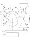
- Fig. 1 illustrates a compound engine assembly 10 in accordance with a particular embodiment, which may be configured for example as a turboprop engine, a turboshaft engine, a turbofan engine, or an auxiliary power unit (APU).
- the engine assembly 10 generally includes a compressor 20, an intermittent internal combustion engine 12 configured for example as a liquid cooled heavy fueled multi-rotor rotary intermittent combustion engine, and a turbine section 18 including one or more turbines.
- the outlet of the compressor 20 is in fluid communication with the inlet of the engine 12; although not shown, such communication may be performed through an intercooler so as to reduce the temperature of the compressed air prior to the compressed air entering the engine 12.
- the compressor 20 includes variable inlet guide vanes 23 through which the air flows before reaching the rotor(s) of the compressor 20.
- the compressor 20 may be a single-stage device or a multiple-stage device and may include one or more rotors having radial, axial or mixed flow blades.
- a source of fuel 14 is in fluid communication with fuel injectors 68, 74, 86 (further described below) of the engine 12.
- the source of fuel 14 is a source of heavy fuel e.g. diesel, kerosene, jet fuel, equivalent biofuel; other suitable types of fuel may alternately be used, including, but not limited to, "light fuel” such as gasoline and naphta.
- the compressed air is mixed with the fuel and combusted to provide power and a residual quantity of exhaust gas.
- the engine 12 drives an engine shaft 16, and provides an exhaust flow in the form of exhaust pulses of high pressure hot gas exiting at high peak velocity.
- the outlet of the engine 12 is in fluid communication with the inlet of the turbine section 18, and accordingly the exhaust flow from the engine 12 is supplied to the turbine(s) of the turbine section 18.
- the turbine section 18 includes at least one turbine rotor engaged on a turbine shaft 19.
- the turbine section 18 includes a first stage turbine 22 receiving the exhaust from the engine 12, and a second stage turbine 24 receiving the exhaust from the first stage turbine 22; each turbine 22, 24 may be a single-stage device or a multiple-stage device and may include one or more rotors having radial, axial or mixed flow blades.
- the turbines 22, 24 have different reaction ratios from one another.
- the first stage turbine 22 is configured to take benefit of the kinetic energy of the pulsating flow exiting the engine 12 while stabilizing the flow and the second stage turbine 24 is configured to extract energy from the remaining pressure in the flow. Accordingly, in a particular embodiment the reaction ratio of the first stage turbine 22 is lower than the reaction ratio of the second stage turbine 24.
- Other configurations are also possible.
- Power from the engine 12 and turbines 22, 24 is compounded to drive a rotatable load 8, for example via a gearbox 26 defining a driving engagement between the engine shaft 16, the turbine shaft 19 and the rotatable load 8.
- the rotatable load 8 may be any suitable type of load including, but not limited to, one or more generator(s), propeller(s), helicopter rotor mast(s), fan(s), compressor(s), or any other appropriate type of load or combination thereof. It is understood that the power from the engine shaft 16 and turbine shaft 19 may be compounded using any other suitable type of engagement, including, but not limited to, by having each shaft engaged to a respective electrical motor/generator with power being transferable between the electrical motor/generators (electrical compounding).
- the compressor 20 is driven by the turbine section 18, by having the rotor(s) of the compressor 20 directly engaged to the turbine shaft 19.
- the rotor(s) of the compressor 20 may be connected to a separate shaft driven by the turbine shaft 19 and/or the engine shaft 16, for example via the gearbox 26 or via a separate gearbox.
- the engine assembly 10 shown is provided as an example only, and that the engine assembly 10 may have any other suitable configuration, including, but not limited to, the configuration of the compound cycle engine system or compound cycle engine such as described in Lents et al.'s US patent No. 7,753,036 issued July 13, 2010 , or such as described in Julien et al.'s US patent No. 7,775,044 issued August 17, 2010 , or such as described in Thomassin et al.'s U.S. patent publication No. 2015/0275749 published October 1, 2015 , or such as described in Bolduc et al.'s U.S. patent publication No. 2015/0275756 published October 1, 2015 .
- the compound engine assembly 10 may be configured as a single shaft engine assembly.
- the compound engine assembly 10 may be used as a prime mover engine, such as on an aircraft or other vehicle, or in any other suitable application.
- the engine assembly 10 may have other configurations than that of a compound engine assembly.
- the turbine section 18 may be omitted, or may rotate independently of the internal combustion engine 12.
- the compressor 20 may be omitted.
- the internal combustion engine 12 may have its inlet and outlet in direct communication with ambient air, i.e. be used without being fluidly connected to a compressor and a turbine.
- the engine 12 is a rotary intermittent internal combustion engine including two or more rotor assemblies 11 drivingly engaged to the engine shaft 16.
- the engine 12 includes a single rotor assembly 11.
- the rotor assembly(ies) are configured as Wankel engines.
- FIG. 2 an example of a Wankel engine which may define a rotor assembly 11 of the engine 12 is shown. It is understood that the configuration of the rotor assembly 11, e.g. placement of ports, number and placement of seals, number of apex portions, combustion chambers, etc., may vary from that of the embodiment shown.
- the rotor assembly 11 comprises a housing 32 defining an internal cavity having a profile defining two lobes, which is preferably an epitrochoid.
- a rotor 34 is received within the internal cavity.
- the rotor 34 in this embodiment defines three circumferentially-spaced apex portions 36, and a generally triangular profile with outwardly arched sides.
- the apex portions 36 are in sealing engagement with the inner surface of a peripheral wall 38 of the housing 32 to form and separate three combustion chambers 40 of variable volume between the rotor 34 and the housing 32.
- the peripheral wall 38 extends between two axially spaced apart end walls 54 to surround the internal cavity.
- the rotor 34 is in driving engagement with the engine shaft 16, by being engaged to an eccentric portion 42 of the engine shaft 16 to perform orbital revolutions within the internal cavity.
- the engine shaft 16 performs three rotations for each orbital revolution of the rotor 34.
- the geometrical axis 44 of the rotor 34 (and of the eccentric portion 42) is offset from and parallel to the central axis 46 of the housing 32 (and of the shaft 16).
- each combustion chamber 40 varies in volume and moves around the internal cavity to undergo the four phases of intake, compression, expansion and exhaust.
- the combustion chambers 40 are sealed by spring-loaded peripheral or apex seals 56 extending from the rotor 34 to engage the inner surface of the peripheral wall 38, and spring-loaded face or gas seals 58 and end or corner seals 60 extending from the rotor 34 to engage the inner surface of the end walls 54.
- the rotor 34 also includes at least one spring-loaded oil seal ring 62 biased against the inner surface of the end wall 54 around the bearing for the rotor 34 on the shaft eccentric portion 42.
- An intake port 48 is defined through the housing 32, for example through the peripheral wall 38.
- the intake port 48 is in fluid communication with each of the combustion chambers 40 in a successive manner, for admitting air (in the embodiment of Fig. 1 , compressed air from the compressor 20) into each of the combustion chambers 40 one after the other.
- the intake port(s) 48 of the rotor assembly(ies) 11 together define the inlet of the engine 12.
- An exhaust port 50 is also provided through the housing 32, for example through the peripheral wall 38.
- the exhaust port 50 is in fluid communication with each of the combustion chambers 40 in a successive manner, for discharge of the exhaust gases from each of the combustion chambers 40 one after the other (which in the embodiment of Fig. 1 is then circulated to the turbine section 18).
- the exhaust port(s) 50 of the rotor assembly(ies) 11 together define the exhaust of the engine 12.
- the intake port 48 and the exhaust port 50 may be provided through the end or side wall 54 of the housing 32.
- the effective volumetric expansion ratio of a combustion chamber 40 can be defined as the ratio between the maximum working volume during the portion of the expansion phase where the combustion chamber 40 does not communicate with the exhaust port 50, and the minimum working volume during the expansion phase.
- the effective volumetric compression ratio of a combustion chamber 40 can be defined as the ratio between the maximum working volume during the portion of the compression phase where the combustion chamber 40 does not communicate with the intake port 48, and the minimum working volume during the compression phase.
- the combustion chambers 40 all have the same effective volumetric compression ratio, which is considered to be the effective volumetric compression ratio of the engine 12, and the combustion chambers 40 all have the same effective volumetric expansion ratio, which is considered to be the effective volumetric expansion ratio of the engine 12.
- the engine 12 operates under the Miller cycle, i.e., with a lower effective volumetric compression ratio than its effective volumetric expansion ratio. This may be obtained, for example, by positioning the intake port 48 to be closer to top dead center (TDC) than the exhaust port 50 to reduce the effective volumetric compression ratio. Alternately, the effective volumetric compression and expansion ratios of the engine 12 may be similar or equal to each other.
- TDC top dead center
- the effective volumetric compression and expansion ratios of the engine 12 may be similar or equal to each other.
- the rotor assembly 11 includes a pilot subchamber 64 in fluid communication with the internal cavity of the housing 32, so as to be in fluid communication with each of the combustion chambers 40 in a successive manner.
- the pilot subchamber 64 has a circular cross-section; alternate shapes are also possible.
- the pilot subchamber 64 communicates with the internal cavity through at least one opening 66 defined through the peripheral wall 38 (as shown) or through the end wall 54.
- the pilot subchamber 64 has a shape forming a reduced cross-section adjacent the opening(s), such that the opening(s) 66 define(s) a restriction to the flow between the pilot subchamber 64 and the internal cavity.
- the opening(s) 66 may have any suitable shape and configuration.
- the pilot subchamber 64 may be defined in an insert made of a material having a greater heat resistance than that of the peripheral wall 38 and end wall 54; in a particular embodiment, the peripheral wall 38 and end wall 54 are made of aluminium.
- inserts are provided in U.S. Patent No. 9,038,594 .
- a main fuel injector 68 is in direct fluid communication with each of the combustion chambers 40 in a successive manner, so as to inject a main quantity of fuel in each of the combustion chambers 40 one after the other.
- the main fuel injector 68 is located downstream of the intake port 48 and upstream of the pilot subchamber 64 with respect to the direction of rotation R of the rotor 34.
- the main fuel injector 68 is a direct fuel injector, i.e. it communicates directly with the internal cavity.
- a main injector opening 70 is defined through the peripheral wall 38 (as shown) or the end wall 54, and extends through the inner surface of the internal cavity.
- the main fuel injector 68 is received in the main injector opening 70 with its tip 72 adjacent the internal cavity.
- the main injector opening 70 is configured so as to avoid interfering (e.g. restricting) the fuel flow from the main fuel injector 68 to the internal cavity.
- a pilot fuel injector 74 is in fluid communication with the pilot subchamber 64, so as to inject a pilot quantity of fuel in the pilot subchamber 64 for each combustion event of the combustion chambers 40.
- the pilot fuel injector 74 communicates directly with the pilot subchamber 64, for example by being received within a corresponding pilot injector opening 76 extending through the peripheral wall 38 (as shown) or the end wall 54 and communicating with the pilot subchamber 64, and having the pilot injector tip 78 received within the pilot subchamber 64 or located adjacent the pilot subchamber 64 (as shown).
- the pilot fuel injector 74 is also in fluid communication with the combustion chambers 40 via the pilot subchamber 64 and the opening(s) 66 defining the communication between the pilot subchamber 64 and the internal cavity.
- An ignition source 80 is in heat exchange relationship with the pilot subchamber 64 so as to perform ignition of the fuel injected within the pilot subchamber 64 by the pilot fuel injector 74.
- the ignition source 80 is a glow plug; the glow plug may for example have a tip 82 received within the pilot subchamber 64 or in a cavity 84 adjacent the pilot subchamber 64 and in fluid communication therewith (as shown).
- the ignition source 80 may also be in heat exchange relationship with the pilot subchamber 64 without fluidly communicating with the pilot subchamber 64.
- the material surrounding the pilot subchamber 64 and defining its inner surface includes heat resistant material which becomes sufficiently hot after the engine 12 has started so as to perform ignition of the fuel injected within the pilot subchamber 64 by the pilot fuel injector 74; in this case, the glow plug may be used only at start up and be turned off when the engine 12 has reached its nominal temperature, so that the walls of the pilot subchamber become the ignition source.
- the main quantity of fuel injected by the main fuel injector 68 can be sized to define a lean fuel-air mixture in the combustion chambers 40.
- the main and pilot fuel injectors 68, 74 together provide for a stratified fuel-air mixture, defined by a stoichiometric or rich fuel-air mixture near the ignition source 80 as provided by the pilot fuel injector 74, and a lean fuel-air mixture in the combustion chambers 40 as provided by the main fuel injector 68.
- an additional fuel injector 86 is provided in fluid communication with each of the combustion chambers 40 in a successive manner, downstream of the pilot subchamber 64 and upstream of the exhaust port 50.
- This additional fuel injector 86 is characterized herein as an "interburner" injector, since it performs an afterburner function while being located inside the engine 12.
- the interburner fuel injector 86 injects a supplemental quantity of fuel in each of the combustion chambers 40 one after the other, during the expansion phase of the cycle while the combustion of the main quantity of fuel is still ongoing, so as to use a portion and potentially a total of the remaining excess air in the combustion chamber 40.
- the interburner fuel injector 86 is in direct fluid communication with each of the combustion chambers 40 in a successive manner, so as to inject the supplemental quantity of fuel in each of the combustion chambers 40 one after the other.
- the interburner fuel injector 86 is a direct fuel injector, i.e. it communicates directly with the internal cavity.
- An interburner injector opening 88 is defined through the peripheral wall 38 (as shown) or the end wall 54, and extends through the inner surface of the internal cavity.
- the interburner fuel injector 86 is received in the interburner injector opening 88 with its tip 90 adjacent the internal cavity.
- the interburner injector opening 88 is configured so as to avoid interfering (e.g. restricting) the fuel flow from the interburner fuel injector 86 to the internal cavity.
- the position of the interburner fuel injector 86 can be varied between the pilot subchamber 64 and the exhaust port 50, for example along region A shown in Fig. 1 .
- the interburner fuel injector 86 is sufficiently close to the pilot subchamber 64 so that each of the combustion chambers 40 is in simultaneous fluid communication with the pilot subchamber 64 and the interburner fuel injector 86 during a respective portion of a revolution of the rotor 34.
- the interburner fuel injector 86 is spaced from the pilot subchamber 64 a distance sufficient to prevent the combustion chambers 40 from simultaneously communicating with the pilot subchamber 64 and the interburner fuel injector 86. If required, cooling can be provided to the nozzle vane of the turbine section 18, particularly, although not exclusively, when the interburner fuel injector 86 is provided in proximity of the exhaust port 50.
- the impact of the interburner fuel injector 86 on the engine cycle differs based on the location of the interburner fuel injector 86.
- Examples of modifications of the temperature-entropy diagram caused by the interburner fuel injector 86 is shown for three different interburner fuel injector locations A 1 , A 2 , A 3 (see Fig. 1 ), as compared to the basic cycle B without the interburner fuel injector 86. It can be seen that the closer the interburner fuel injector is to the pilot subchamber, the higher the temperature of the fuel-air mixture is upon injection of the supplemental quantity of fuel, and the greater the impact on the combustion cycle.
- having the interburner fuel injector 86 located closer to the pilot subchamber 64 allows to increase the power produced by the engine, as well as decrease the unburned hydrocarbons (HC) since a higher maximum temperature can be reached (see e.g. curve A 1 as compared to curve A 3 ), however causes the mechanical and thermal loading on the engine as well as the NOx emissions to increase, as compared to a interburner fuel injector 86 location further away from the pilot subchamber 64.
- the location of the interburner fuel injector 86 is selected so as to obtain the best possible trade between additional power, combustion efficiency, emissions and additional loading to the rotary portion of the engine.
- the main fuel injector 68, the pilot fuel injector 74 and the interburner fuel injector 86 are in fluid communication with the fuel source 14 ( Fig. 1 ); although a common source is shown, it is understood that separate sources could alternately be provided. Accordingly, in a particular embodiment the main fuel injector 68, the pilot fuel injector 74 and the interburner fuel injector 86 inject the fuel, e.g. heavy fuel such as diesel, kerosene, jet fuel, equivalent biofuel, etc. In a particular embodiment the fuel injectors 68, 74, 86 are common rail fuel injectors, fed by the same or by different common rails (not shown).
- fuel e.g. heavy fuel
- the main quantity of fuel is directly injected into the combustion chamber 40 by the main fuel injector 68 so as to form a first fuel-air mixture within the combustion chamber 40, the first fuel mixture being lean.
- the main quantity of fuel can be provided in a single or multiple sprays, and when multiple sprays are used, the multiple sprays can be simultaneous or be sequential.
- compressed air from the compressor 20 ( Fig. 1 ) is fed into the combustion chamber 40 through the intake port 48 before injecting the main quantity of fuel to create the first fuel-air mixture.
- ambient air may be fed into the combustion chamber 40 through the intake port 48 to create the first fuel-air mixture.
- the first fuel-air mixture is lean and accordingly has an air-fuel equivalence ratio ⁇ higher than 1.
- the air-fuel equivalence ratio A of the first fuel-air mixture formed by the main quantity of fuel is at least 1.6.
- the air-fuel equivalence ratio ⁇ of the first fuel-air mixture formed by the main quantity of fuel is at least 2, for example within the range defined from 2 to 2.3.
- the mass is the mass of all constituents that compose the fuel and air, whether combustible or not.
- the air-fuel equivalence ratio ⁇ is greater than 1 with leaner fuel-air mixtures having a greater value of ⁇ , while rich fuel-air mixtures have an air-fuel equivalence ratio ⁇ lower than 1 with richer fuel-air mixtures having a smaller value of ⁇ .
- the first fuel-air mixture formed within the combustion chamber by the injection of the main quantity of fuel has a fuel-air equivalence ratio ⁇ lower than 1, for example within a range defined from 0.1 to 0.6.
- the pilot quantity of fuel is injected into the pilot subchamber 64 by the pilot fuel injector 74 to form a second fuel-air mixture within the pilot subchamber 64.
- the pilot quantity of fuel can be provided in a single or multiple sprays, and when multiple sprays are used, the multiple sprays can be simultaneous or be sequential.
- This second fuel-air mixture has an air-fuel equivalence ratio ⁇ which is smaller than the air-fuel equivalence ratio ⁇ of the combustion chamber 40, i.e. the fuel-air mixture is richer within the pilot subchamber 64 and leaner within the combustion chamber 40.
- the fuel-air mixture within the pilot subchamber 64 is close to stoichiometry; in a particular embodiment, the air-fuel equivalence ratio A of the fuel-air mixture within the pilot subchamber 64 is at most 1.
- the stoichiometric or rich fuel-air mixture within the pilot subchamber 64 is then ignited.
- the fuel-air mixture within the pilot subchamber 64 may be ignited for example by the glow plug 80 and/or the hot subchamber wall.
- the ignited fuel-air mixture is then used to ignite the first fuel-air mixture in the combustion chamber 40; the ignited pilot fuel-air mixture flows from the pilot subchamber 64 through the opening(s) 66 and forms a flame expelled into the combustion chamber 40 and allowing for ignition of the lean fuel-air mixture of the combustion chamber 40.
- the supplemental quantity of fuel is then injected by the interburner fuel injector 86 directly into the combustion chamber 40 after ignition of the first fuel-air mixture, e.g. during combustion of the first fuel-air mixture. It is understood that the supplemental quantity of fuel can be provided in a single or multiple sprays, and when multiple sprays are used, the multiple sprays can be simultaneous or be sequential. Since combustion is still active in the combustion chamber 40, ignition of the supplemental quantity of fuel injected by the interburner fuel injector 86 is practically instantaneous.
- the supplemental quantity of fuel is injected upstream of the exhaust port 50 with respect to the direction of rotation R of the rotor. As mentioned above, depending on the location of the interburner fuel injector 86, the supplemental quantity of fuel may be injected while the combustion chamber 40 communicates with the pilot subchamber 64, or after the communication between the combustion chamber 40 and the pilot subchamber 64 is closed.
- the combustion exhaust is fed from the exhaust port 50 to the turbine section 18, and power from the turbine shaft 19 is compounded with power from the engine shaft 16.
- the combustion may be fed from the exhaust port 50 to a turbine without compounding power between the engine and turbine, or may be fed elsewhere, e.g. to ambient air in the environment around the engine assembly 10.
- the supplemental quantity of fuel injected into the combustion chamber 40 increases the fuel-air equivalence ratio ⁇ in the combustion chamber 40 (and accordingly, reduces the air-fuel equivalence ratio ⁇ );
- Fig. 4 shows the coefficient of variance of the indicated mean effective pressure OOV IMEP as a function of the fuel-air equivalence ratio ⁇ of the fuel-air mixture in the combustion chamber 40 without the supplemental fuel injection (B) and with the supplemental fuel injection (A').
- the fuel-air equivalence ratio ⁇ within the combustion chamber 40 increases from a value within a range defined from 0.1 to 0.6 to a value of at least 0.6, or to a value within a range from 0.6 to 0.85, when the supplemental quantity of fuel is injected.
- the supplemental quantity of fuel injected by the interburner fuel injector 86 thus reduces the air-fuel equivalence ratio A within the combustion chamber, for example from a value within a range defined from 2 to 2.3 (fuel-air equivalence ratio ⁇ from 0.43 to 0.5), to a value of at most 1.67 (fuel-air equivalence ratio ⁇ of at least 0.6), or to a value within a range defined from 1.18 to 1.67 (fuel-air equivalence ratio ⁇ from 0.6 to 0.85). In a particular embodiment, this allows to provide more power within the same size engine and thus increase power to weight capability.
- the supplemental quantity of fuel injected by the interburner fuel injector 86 also slightly increases the coefficient of variance of the indicated mean effective pressure COV IMEP , and accordingly slightly increases the variability of the cycle and thus slightly decreases the stability of the combustion process, while still allowing the stability to remain within acceptable limits.
- the coefficient of variance of the indicated mean effective pressure COV IMEP is within a range defined from 0 to 3% (e.g.
- the indicated mean effective pressure COV IMEP increases the coefficient of variance of the indicated mean effective pressure COV IMEP depending on the change of fuel-air equivalence ratios ⁇ in the combustion chamber caused by the injection of the supplemental quantity of fuel; for example, at a fuel-air equivalence ratio ⁇ of about 0.85, the indicated mean effective pressure COV IMEP increases within a range defined from 2% to 5% (e.g. from 2% to 3.5% as shown). Other values are also possible.
- the main quantity of fuel injected by the main fuel injector 68 is greater than the supplemental quantity of fuel injected by the interburner fuel injector 86, and the supplemental quantity of fuel injected by the interburner fuel injector 86 is greater than the pilot quantity of fuel injected by the pilot fuel injector 74.
- the sum of the pilot quantity, main quantity and supplemental quantity injected for a same combustion event defines a total quantity of fuel, which is distributed in accordance with the following: the pilot quantity injected by the pilot fuel injector 74 corresponds to 2% to 10% of the total quantity of fuel, the supplemental quantity injected by the interburner fuel injector 86 corresponds to 10 to 40% of the total quantity of fuel, and the main quantity of fuel injected by the main fuel injector 68 corresponds to at least 50% of the total quantity of fuel, e.g. the remaining 50% to 88% of the total quantity of fuel.
- the pilot quantity injected by the pilot fuel injector 74 corresponds about 5% of the total quantity of fuel
- the supplemental quantity injected by the interburner fuel injector 86 corresponds to about 20% of the total quantity of fuel
- the main quantity of fuel injected by the main fuel injector 68 corresponds to about 75% of the total quantity of fuel.
- Other values are also possible.
- the supplemental quantity injected by the interburner fuel injector 86 allows to inject additional heat in the system at lower than peak pressure, which minimizes the additional mechanical loading created by the additional heat.
- the supplemental quantity injected by the interburner fuel injector 86 corresponds to about 10% of the total quantity of fuel, and this produces an increase in the power generated by the engine of about 20% with minimal mechanical loading increase. Accordingly, in a particular embodiment the interburner fuel injector 86 significantly improves both the power density and specific fuel consumption of the engine.
Landscapes
- Engineering & Computer Science (AREA)
- Chemical & Material Sciences (AREA)
- Combustion & Propulsion (AREA)
- Mechanical Engineering (AREA)
- General Engineering & Computer Science (AREA)
- Combustion Methods Of Internal-Combustion Engines (AREA)
- Electrical Control Of Air Or Fuel Supplied To Internal-Combustion Engine (AREA)
Claims (16)
- Verfahren zum Verbrennen von Kraftstoff (14) in einem Rotationskolbenmotor (12), wobei das Verfahren Folgendes umfasst:Einspritzen einer Hauptmenge des Kraftstoffs (14), wahlweise schweren Kraftstoffs, direkt in eine Brennkammer (40) des Rotationskolbenmotors (12), um ein erstes Kraftstoff-Luft-Gemisch innerhalb der Brennkammer (40) zu bilden, wobei das erste Kraftstoff-Luft-Gemisch ein erstes Luft-Kraftstoff-Äquivalenzverhältnis λ von mehr als 1 aufweist;Einspritzen einer Pilotmenge des Kraftstoffs (14) in eine Pilotteilkammer (64), um ein zweites Kraftstoff-Luft-Gemisch innerhalb der Pilotteilkammer (64) zu bilden, wobei das zweite Kraftstoff-Luft-Gemisch ein zweites Luft-Kraftstoff-Äquivalenzverhältnis λ von weniger als das erste Luft-Kraftstoff-Äquivalenzverhältnis aufweist;Zünden des zweiten Kraftstoff-Luft-Gemischs innerhalb der Pilotteilkammer (64);Verwenden des gezündeten zweiten Kraftstoff-Luft-Gemischs aus der Pilotteilkammer (64) dazu, das erste Kraftstoff-Luft-Gemisch zu zünden; undnach dem Zünden des ersten Kraftstoff-Luft-Gemischs, Einspritzen einer zusätzlichen Menge des Kraftstoffs direkt in die Brennkammer (40), wobei die zusätzliche Menge stromaufwärts eines Abgasanschlusses (50) des Rotationskolbenmotors (12) in Bezug auf eine Drehrichtung (R) eines Rotors (34) eingespritzt wird.
- Verfahren nach Anspruch 1, wobei die zusätzliche Menge an Kraftstoff eingespritzt wird, während die Verbrennung des ersten Kraftstoff-Luft-Gemischs aktiv ist.
- Verfahren nach Anspruch 1 oder 2, das ferner ein Zuführen von verdichteter Luft in die Brennkammer (40) vor dem Einspritzen der Hauptmenge umfasst.
- Verfahren nach einem der vorhergehenden Ansprüche, das ferner ein Zuführen von Abgas aus dem Abgasanschluss (50) des Rotationskolbenmotors (12) an eine Turbine (22, 24) und ein Verstärken von Leistung von einer Turbinenwelle (19) der Turbine (22, 24) mit Leistung von einer Motorwelle (16) umfasst, die antriebsmäßig mit dem Rotor (34) in Eingriff steht.
- Verfahren nach einem der vorhergehenden Ansprüche, wobei die zusätzliche Menge eingespritzt wird, während die Brennkammer (40) mit der Pilotteilkammer (64) kommuniziert.
- Verfahren nach einem der Ansprüche 1 bis 4, wobei die zusätzliche Menge eingespritzt wird, nachdem eine Kommunikation zwischen der Brennkammer (40) und der Pilotteilkammer (64) abgeschlossen ist.
- Verfahren nach einem der vorhergehenden Ansprüche, wobei das zweite Luft-Kraftstoff-Äquivalenzverhältnis höchstens 1 ist.
- Verfahren nach einem der vorhergehenden Ansprüche, wobei das erste Luft-Kraftstoff-Äquivalenzverhältnis des ersten Kraftstoff-Luft-Gemischs, das durch die Hauptmenge gebildet ist, mindestens 1,67, wahlweise mindestens 2 und/oder höchstens 2,3 ist.
- Verfahren nach einem der vorhergehenden Ansprüche, wobei das Zünden des zweiten Kraftstoff-Luft-Gemischs mit einer Glühkerze (80) oder mit heißen Wänden der Pilotteilkammer (64) durchgeführt wird.
- Verfahren nach einem der vorhergehenden Ansprüche, wobei die Hauptmenge größer als die zusätzliche Menge ist und die zusätzliche Menge größer als die Pilotmenge ist.
- Verfahren nach Anspruch 10, wobei eine Summe der Pilotmenge, der Hauptmenge und der zusätzlichen Menge eine Gesamtmenge definiert, und wobei:Einspritzen der Pilotmenge ein Einspritzen von 2 % bis 10 %, und wahlweise 5 %, der Gesamtmenge in die Pilotteilkammer (64) beinhaltet;Einspritzen der Hauptmenge ein Einspritzen von mindestens 50 %, und wahlweise 75 %, der Gesamtmenge in die Brennkammer (40) beinhaltet; undEinspritzen der zusätzlichen Menge ein Einspritzen von 10 bis 40 %, und wahlweise 20 %, der Gesamtmenge in die Brennkammer (40) beinhaltet.
- Rotationskolbenmotor (12), der Folgendes umfasst:einen Rotor (34), der abdichtend innerhalb eines inneren Hohlraums eines Gehäuses (32) aufgenommen ist, um eine Vielzahl von Brennkammern (40) zu definieren, die ein variables Volumen aufweisen;einen Einlassanschluss (48) und einen Abgasanschluss (50), die durch das Gehäuse (32) definiert sind und in Fluidverbindung mit jeder der Brennkammern (40) auf eine aufeinanderfolgende Weise stehen;eine Pilotteilkammer (64) in Fluidverbindung mit jeder der Brennkammern (40) auf eine aufeinanderfolgende Weise;eine Hauptkraftstoffeinspritzvorrichtung (68) in direkter Fluidverbindung mit jeder der Brennkammern (40) auf eine aufeinanderfolgende Weise, wobei sich die Hauptkraftstoffeinspritzvorrichtung (68) stromabwärts des Einlassanschlusses (48) und stromaufwärts der Pilotteilkammer (64) in Bezug auf eine Drehrichtung (R) des Rotors (34) befindet;eine Pilotkraftstoffeinspritzvorrichtung (74) in Fluidverbindung mit der Pilotteilkammer (64);eine Zündquelle (80) im Wärmetauschverhältnis mit der Pilotteilkammer (64); undeine Nachbrennerkraftstoffeinspritzvorrichtung (86) in direkter Fluidverbindung mit jeder der Brennkammern (40) auf eine aufeinanderfolgende Weise, wobei sich die Nachbrennerkraftstoffeinspritzvorrichtung (86) stromabwärts der Pilotteilkammer (64) und stromaufwärts des Abgasauslasses (50) befindet, wobei Kraftstoff in dem Rotationskolbenmotor (12) gemäß dem Verfahren nach einem der vorhergehenden Ansprüche verbrannt wird.
- Rotationskolbenmotor (12) nach Anspruch 12, der ferner eine Quelle (14) von schwerem Kraftstoff in Fluidverbindung mit der Hauptkraftstoffeinspritzvorrichtung (68), der Pilotkraftstoffeinspritzvorrichtung (74) und der Nachbrennerkraftstoffeinspritzvorrichtung (86) umfasst.
- Rotationskolbenmotor (12) nach Anspruch 12 oder 13, wobei jede der Brennkammer (40) in gleichzeitiger Fluidverbindung mit der Pilotteilkammer (64) und der Nachbrennerkraftstoffeinspritzvorrichtung (86) während eines entsprechenden Abschnitts einer Umdrehung des Rotors (34) steht und wobei eine Nachbrennerkraftstoffeinspritzvorrichtung (86) wahlweise von der Pilotteilkammer (64) um eine Entfernung beabstandet ist, die ausreicht, um die Brennkammern (40) daran zu hindern, gleichzeitig mit der Pilotteilkammer (64) und der Nachbrennerkraftstoffeinspritzvorrichtung (86) zu kommunizieren.
- Rotationskolbenmotor (12) nach einem der Ansprüche 12 bis 14, wobei die Zündquelle (80) eine Glühkerze (80) ist und wobei wahlweise der Rotationskolbenmotor (12) ein Wankelmotor (12) ist, der innere Hohlraum ein Profil aufweist, das zwei Vorsprünge definiert, der Rotor (34) drei in Umfangsrichtung beabstandete Scheitelabschnitte (36) in abdichtendem Eingriff mit einer Umfangswand (38) des Gehäuses (32) und die die Brennkammern (40) trennen aufweist.
- Verbundtriebwerkbaugruppe (10), die den Rotationskolbenmotor (12) nach einem der Ansprüche 12 bis 15, einen Verdichter (20) in Fluidverbindung mit dem Einlassanschluss (48) des Rotationskolbenmotors (12) und eine Turbine (22, 24) in Fluidverbindung mit dem Abgasanschluss (50) des Rotationskolbenmotors (12) umfasst, wobei die Turbine (22, 24) eine Turbinenwelle (19) aufweist, die mit einer Motorwelle (16) verbunden ist, die antriebsmäßig mit dem Rotor (34) in Eingriff steht.
Priority Applications (1)
| Application Number | Priority Date | Filing Date | Title |
|---|---|---|---|
| PL18199360T PL3470649T3 (pl) | 2017-10-10 | 2018-10-09 | Silnik obrotowy i sposób spalania paliwa |
Applications Claiming Priority (1)
| Application Number | Priority Date | Filing Date | Title |
|---|---|---|---|
| US15/729,043 US10145291B1 (en) | 2017-10-10 | 2017-10-10 | Rotary engine and method of combusting fuel |
Publications (2)
| Publication Number | Publication Date |
|---|---|
| EP3470649A1 EP3470649A1 (de) | 2019-04-17 |
| EP3470649B1 true EP3470649B1 (de) | 2021-06-09 |
Family
ID=63832214
Family Applications (1)
| Application Number | Title | Priority Date | Filing Date |
|---|---|---|---|
| EP18199360.1A Active EP3470649B1 (de) | 2017-10-10 | 2018-10-09 | Rotationskolbenmotor und verfahren zur kraftstoffverbrennung |
Country Status (5)
| Country | Link |
|---|---|
| US (2) | US10145291B1 (de) |
| EP (1) | EP3470649B1 (de) |
| CA (1) | CA3017657A1 (de) |
| ES (1) | ES2882726T3 (de) |
| PL (1) | PL3470649T3 (de) |
Families Citing this family (29)
| Publication number | Priority date | Publication date | Assignee | Title |
|---|---|---|---|---|
| US10557407B2 (en) * | 2011-07-28 | 2020-02-11 | Pratt & Whitney Canada Corp. | Rotary internal combustion engine with pilot subchamber |
| US9528434B1 (en) * | 2011-07-28 | 2016-12-27 | Pratt & Whitney Canada Corp. | Rotary internal combustion engine with pilot subchamber |
| US10907531B1 (en) * | 2018-07-24 | 2021-02-02 | Rotary Research Group LLC | Heavy fuel rotary engine with compression ignition |
| US11628942B2 (en) | 2019-03-01 | 2023-04-18 | Pratt & Whitney Canada Corp. | Torque ripple control for an aircraft power train |
| US11427344B2 (en) | 2019-03-01 | 2022-08-30 | Pratt & Whitney Canada Corp. | Cooling system configurations for an aircraft having hybrid-electric propulsion system |
| US11697505B2 (en) | 2019-03-01 | 2023-07-11 | Pratt & Whitney Canada Corp. | Distributed propulsion configurations for aircraft having mixed drive systems |
| CA3133744A1 (en) | 2019-04-25 | 2020-10-29 | United Technologies Advanced Projects, Inc. | Aircraft degraded operation ceiling increase using electric power boost |
| US20210047026A1 (en) | 2019-08-15 | 2021-02-18 | Hamilton Sundstrand Corporation | Taxiing an aircraft having a hybrid propulsion system |
| US11667391B2 (en) | 2019-08-26 | 2023-06-06 | Pratt & Whitney Canada Corp. | Dual engine hybrid-electric aircraft |
| US11912422B2 (en) | 2019-08-26 | 2024-02-27 | Hamilton Sundstrand Corporation | Hybrid electric aircraft and powerplant arrangements |
| US12535014B2 (en) | 2019-09-06 | 2026-01-27 | Hamilton Sundstrand Corporation | Vortex turbines for a hybrid-electric aircraft |
| CA3101391A1 (en) | 2019-12-03 | 2021-06-03 | United Technologies Advanced Projects, Inc. | Aircraft propulsion system and methods of feathering |
| US11486472B2 (en) | 2020-04-16 | 2022-11-01 | United Technologies Advanced Projects Inc. | Gear sytems with variable speed drive |
| US11794917B2 (en) | 2020-05-15 | 2023-10-24 | Pratt & Whitney Canada Corp. | Parallel control loops for hybrid electric aircraft |
| US11827372B2 (en) | 2020-05-15 | 2023-11-28 | Pratt & Whitney Canada Corp. | Engine characteristics matching |
| US11958622B2 (en) | 2020-05-15 | 2024-04-16 | Pratt & Whitney Canada Corp. | Protection functions |
| US11506116B2 (en) | 2020-11-04 | 2022-11-22 | William Todd Hodges | Rotary combustion engine with integrated multistage fuel system |
| US11365706B2 (en) | 2020-11-04 | 2022-06-21 | William Todd Hodges | Turbine engine system utilizing an augmented combustion module |
| US11619165B1 (en) | 2020-11-04 | 2023-04-04 | William Todd Hodges | Rotary combustion engine with integrated multistage fuel system |
| CN113006933B (zh) * | 2021-03-12 | 2022-08-02 | 北京工业大学 | 一种缸盖对置点火转子机及其控制方法 |
| CN112832904A (zh) * | 2021-03-23 | 2021-05-25 | 西安交通大学 | 一种小型多种燃料三角转子发动机及工作方式 |
| US11866181B2 (en) | 2021-09-15 | 2024-01-09 | Pratt & Whitney Canada Corp. | Aircraft power plant |
| CN114542341B (zh) * | 2022-02-25 | 2024-04-05 | 江苏方霖动力科技有限公司 | 一种发动机燃油喷油系统及喷油方法 |
| EP4290061B1 (de) | 2022-06-06 | 2026-03-25 | Volvo Construction Equipment AB | Kraftstoffinjektionssystem und -verfahren |
| US12078353B2 (en) * | 2022-11-24 | 2024-09-03 | Pratt & Whitney Canada Corp. | Aircraft power plant with interburner |
| US12006882B1 (en) | 2023-06-08 | 2024-06-11 | Pratt & Whitney Canada Corp. | Rotary engine with dual-fuel injectors |
| US11905836B1 (en) | 2023-06-08 | 2024-02-20 | Pratt & Whitney Canada Corp. | Rotary engine with single dual-fuel injector |
| US12234765B1 (en) * | 2024-01-16 | 2025-02-25 | Pratt & Whitney Canada Corp. | Rotary engine with fluid injection cooling |
| US12583596B2 (en) * | 2024-02-07 | 2026-03-24 | Pratt & Whitney Canada Corp. | Aircraft propulsion system |
Family Cites Families (164)
| Publication number | Priority date | Publication date | Assignee | Title |
|---|---|---|---|---|
| US3126876A (en) | 1964-03-31 | Fuel injection systems for rotary combustion engines | ||
| US1539133A (en) | 1920-08-13 | 1925-05-26 | Harry Newton Hocken | Spark-plug attachment |
| US2093339A (en) | 1932-03-12 | 1937-09-14 | Oilmotors Corp | Internal combustion engine |
| US2739578A (en) | 1950-07-20 | 1956-03-27 | Daimler Benz Ag | Precombustion diesel engine |
| US2935054A (en) | 1957-03-08 | 1960-05-03 | Kloeckner Humboldt Deutz Ag | Fuel injection internal combustion engine |
| US2932289A (en) | 1958-10-20 | 1960-04-12 | Julius E Witzky | Precombustion chamber |
| US3058452A (en) | 1959-03-14 | 1962-10-16 | Motoren Werke Mannheim Ag | Internal combustion engines |
| US3044454A (en) | 1959-04-07 | 1962-07-17 | Rover Co Ltd | Combustion chambers of compression ignition internal combustion engines |
| US3102521A (en) | 1960-12-20 | 1963-09-03 | Fmc Corp | Combustion apparatus for an internal combustion engine |
| DE1401982A1 (de) | 1961-12-09 | 1969-05-22 | Krupp Gmbh | Rotationskolbenmaschine |
| US3246636A (en) | 1965-04-15 | 1966-04-19 | Curtiss Wright Corp | Rotary combustion engine and method of operating same |
| GB1193878A (en) | 1966-06-15 | 1970-06-03 | Dynatech Corp | Internal Combustion Engine |
| US3512907A (en) | 1968-04-25 | 1970-05-19 | Nsu Motorenwerke Ag | Rotary combustion engine |
| US3508530A (en) | 1968-05-23 | 1970-04-28 | Dynatech Corp | Internal combustion engine |
| SU847937A3 (ru) | 1970-05-02 | 1981-07-15 | За витель | Двигатель внутреннего сгорани |
| US3857369A (en) | 1971-04-27 | 1974-12-31 | H Sabet | Rotary piston engine with auxiliary chamber on its casing |
| IT964079B (it) | 1971-09-25 | 1974-01-21 | Sabet Huschang | Motore a pistoni in moto di circolazione |
| US3722480A (en) | 1971-12-20 | 1973-03-27 | Curtiss Wright Corp | Rotary combustion engine with improved firing channel |
| US4096828A (en) | 1972-01-24 | 1978-06-27 | Toyo Kogyo Co. Ltd. | Rotary piston internal combustion engine |
| JPS5218849B2 (de) | 1972-05-15 | 1977-05-24 | ||
| JPS4917910U (de) * | 1972-05-24 | 1974-02-15 | ||
| US3941097A (en) | 1973-06-09 | 1976-03-02 | Audi Nsu Auto Union Aktiengesellschaft | Rotary combustion engine having improved ignition means |
| GB1437528A (en) | 1973-10-09 | 1976-05-26 | Rolls Royce Motors Ltd | Combustion chamber arrangement for rotary compression-ignition engines |
| US3861361A (en) | 1973-11-29 | 1975-01-21 | Gen Motors Corp | Rotary engine with piston scavenged precombustion chambers |
| US3894518A (en) | 1973-12-12 | 1975-07-15 | Curtiss Wright Corp | Stratified charge rotary engine with dual fuel injection |
| JPS5216765B2 (de) * | 1974-01-25 | 1977-05-11 | ||
| US4009688A (en) | 1974-03-04 | 1977-03-01 | Toyo Kogyo Co., Ltd. | Rotary piston type engine |
| US3910238A (en) | 1974-06-10 | 1975-10-07 | Richard James | Piston power unit with stratifying ignition system |
| JPS5129102U (de) | 1974-08-27 | 1976-03-02 | ||
| US3960115A (en) * | 1974-10-04 | 1976-06-01 | Curtiss-Wright Corporation | Stratified charge rotary engine (method of operation) |
| US3957021A (en) | 1974-10-15 | 1976-05-18 | Curtiss-Wright Corporation | Precombustion chamber rotary piston diesel engine |
| US3987759A (en) | 1975-06-03 | 1976-10-26 | Curtiss-Wright Corporation | Stratified charge rotary engine with variable spray angle fuel nozzle |
| JPS5222617A (en) | 1975-08-15 | 1977-02-21 | Toyota Motor Corp | Fuel supply device of rotary piston engine |
| US4060058A (en) | 1975-11-28 | 1977-11-29 | Ford Motor Company | Internal combustion engine control system |
| JPS5266107A (en) | 1975-11-29 | 1977-06-01 | Riken Piston Ring Ind Co Ltd | Rotary piston engine |
| US4057036A (en) | 1976-03-01 | 1977-11-08 | Caterpillar Tractor Co. | Rotary engine with variable orifice prechamber |
| US4029058A (en) | 1976-03-15 | 1977-06-14 | Curtiss-Wright Corporation | Stratified charge rotary engine with side housing fuel injection |
| US4259932A (en) | 1976-05-26 | 1981-04-07 | Ford Motor Company | Internal combustion engine control system |
| US4089306A (en) | 1976-06-09 | 1978-05-16 | Caterpillar Tractor Co. | Port insulation for internal combustion engines |
| US4080934A (en) | 1976-09-09 | 1978-03-28 | Curtiss-Wright Corporation | Rotary engine with inserts in rotor faces |
| US4066044A (en) | 1976-09-09 | 1978-01-03 | Curtiss-Wright Corporation | Rotary engine with tongue and groove inserts in rotor faces |
| US4091789A (en) | 1977-02-11 | 1978-05-30 | Curtiss-Wright Corporation | Stratified charge fuel injection system for rotary engine |
| US4085712A (en) | 1977-02-14 | 1978-04-25 | Curtiss-Wright Corporation | Rotary engine with pilot and main fuel nozzles downstream of top center |
| US4083329A (en) | 1977-02-14 | 1978-04-11 | Curtiss-Wright Corporation | Rotary engine with a pilot fuel nozzle downstream of top center |
| JPS5496614A (en) | 1978-01-13 | 1979-07-31 | Isuzu Motors Ltd | Voltex flow type conbustion chamber |
| US4239023A (en) | 1978-12-07 | 1980-12-16 | Ford Motor Company | Fuel injection system for dual combustion chamber engine |
| DE2912155A1 (de) | 1979-03-28 | 1980-10-09 | Kloeckner Humboldt Deutz Ag | Luftverdichtende, selbstzuendende hubkolbenbrennkraftmaschine |
| US4270499A (en) | 1979-05-03 | 1981-06-02 | General Motors Corporation | Diesel engine precombustion chambers |
| JPS55176435U (de) | 1979-06-05 | 1980-12-18 | ||
| JPS5917252B2 (ja) | 1980-12-15 | 1984-04-20 | マツダ株式会社 | 過給機付ロ−タリピストンエンジンの吸気装置 |
| JPS5790251A (en) | 1981-09-30 | 1982-06-04 | Nissin Kogyo Kk | Negative pressure activated toggle joint and connector for master cylinder |
| JPS5865930A (ja) | 1981-10-15 | 1983-04-19 | Nissan Motor Co Ltd | 副噴口付渦流室式デイ−ゼルエンジン |
| JPS58162721A (ja) | 1982-03-19 | 1983-09-27 | Ngk Spark Plug Co Ltd | 内燃機関の副燃焼室 |
| JPS597726A (ja) | 1982-07-05 | 1984-01-14 | Mazda Motor Corp | デイ−ゼルエンジンの副室構成部材取付構造 |
| JPS5917252A (ja) | 1982-07-21 | 1984-01-28 | Hitachi Ltd | 半導体装置の製造方法 |
| JPS5946317A (ja) | 1982-09-07 | 1984-03-15 | Toyota Motor Corp | 内燃機関の燃焼室部品 |
| JPS59200012A (ja) | 1983-04-27 | 1984-11-13 | Kyocera Corp | 内燃機関の副燃焼室 |
| DE3475932D1 (en) | 1983-10-06 | 1989-02-09 | Mazda Motor | Structure of divided combustion chamber for diesel engine |
| JPS6093124A (ja) | 1983-10-27 | 1985-05-24 | Mazda Motor Corp | ロ−タリピストンエンジンの吸気装置 |
| JPS60153420A (ja) | 1984-01-21 | 1985-08-12 | Mitsubishi Heavy Ind Ltd | 副室式機関の燃焼室 |
| JPS60212614A (ja) | 1984-04-06 | 1985-10-24 | Ngk Spark Plug Co Ltd | 内燃機関の副室 |
| DE3519835A1 (de) | 1984-06-07 | 1985-12-12 | Nissan Motor Co., Ltd., Yokohama, Kanagawa | Verbrennungsmotor |
| DE3520775A1 (de) | 1984-06-12 | 1985-12-12 | Nissan Motor Co., Ltd., Yokohama, Kanagawa | Dieselmotor mit einer wirbelkammer und einer im kolbenboden eingeformten flammenverteilungsaussparung |
| JPS6183451A (ja) | 1984-09-29 | 1986-04-28 | Mazda Motor Corp | エンジンの副室の製造法 |
| JPS6193227A (ja) | 1984-10-11 | 1986-05-12 | Mazda Motor Corp | エンジンの副室の製造法 |
| US4616611A (en) | 1984-10-16 | 1986-10-14 | Ngk Insulators, Ltd. | Precombustion chamber construction of internal combustion engine |
| JPH0223788Y2 (de) | 1984-10-17 | 1990-06-28 | ||
| US4672933A (en) | 1984-10-30 | 1987-06-16 | 501 NGK Spark Plug Co. Ltd. | Precombustion chamber with insulating means |
| JPS61123714A (ja) | 1984-11-20 | 1986-06-11 | Ngk Insulators Ltd | 内燃機関の副室構造 |
| FR2575522B1 (fr) | 1984-12-28 | 1989-04-07 | Inst Francais Du Petrole | Dispositif pour controler le jet de melange carbure delivre par un systeme d'injection pneumatique |
| JPS61171821A (ja) | 1985-01-25 | 1986-08-02 | Nissan Motor Co Ltd | 渦流室付きデイ−ゼル機関 |
| JPH0212265Y2 (de) | 1985-06-24 | 1990-04-06 | ||
| JPS6210418A (ja) | 1985-07-08 | 1987-01-19 | Mazda Motor Corp | 内燃機関のセラミックス製副室 |
| JPH029067Y2 (de) | 1985-07-30 | 1990-03-06 | ||
| JPS63179134A (ja) | 1986-10-29 | 1988-07-23 | Mazda Motor Corp | エンジンの吸気装置 |
| JPH0726553B2 (ja) | 1986-10-31 | 1995-03-29 | マツダ株式会社 | エンジンの吸気装置 |
| JPH0799114B2 (ja) | 1986-12-20 | 1995-10-25 | マツダ株式会社 | エンジンの制御装置 |
| US4759325A (en) | 1987-01-28 | 1988-07-26 | Deere & Company | Rotary engine cooling system |
| JPH0536990Y2 (de) | 1987-02-23 | 1993-09-20 | ||
| US4873952A (en) | 1987-03-02 | 1989-10-17 | Ngk Spark Plug Co., Ltd. | Engine cylinder head with precombustion chambers using porous ceramics insert |
| JPS63140134U (de) | 1987-03-06 | 1988-09-14 | ||
| JPS6421220U (de) | 1987-07-29 | 1989-02-02 | ||
| JPS6480722A (en) | 1987-09-21 | 1989-03-27 | Mazda Motor | Intra-cylinder injection type engine |
| JPH01151722A (ja) | 1987-12-07 | 1989-06-14 | Mazda Motor Corp | エンジンの燃料噴射装置 |
| JPH0814253B2 (ja) | 1987-12-24 | 1996-02-14 | 三菱重工業株式会社 | 副室式ディーゼル機関の燃焼室 |
| JP2689132B2 (ja) | 1988-06-02 | 1997-12-10 | ヤマハ発動機株式会社 | 2サイクルディーゼルエンジン |
| US4889931A (en) | 1988-09-27 | 1989-12-26 | Salutar, Inc. | Manganese (II) chelate manufacture |
| US5335061A (en) | 1989-02-27 | 1994-08-02 | Olympus Optical Co., Ltd. | Endoscope holding apparatus for inspecting the interiors of a reciprocating engine and rotary engine having ignition plug holes, endoscope apparatus including the endoscope holding apparatus and inspecting method |
| JPH033940A (ja) | 1989-05-31 | 1991-01-10 | Mazda Motor Corp | エンジンの燃料噴射制御装置 |
| JPH0357817A (ja) | 1989-07-27 | 1991-03-13 | Isuzu Motors Ltd | 副室の断熱構造 |
| US5022366A (en) | 1989-09-18 | 1991-06-11 | John Deere Technologies International, Inc. | Rotary engine with dual spark plugs and fuel injectors |
| US5178104A (en) | 1989-09-29 | 1993-01-12 | Yamaha Hatsudoki Kabushiki Kaisha | Two cycle diesel engine |
| JPH03199627A (ja) | 1989-12-28 | 1991-08-30 | Mazda Motor Corp | エンジンの吸気装置 |
| JPH03210027A (ja) | 1990-01-13 | 1991-09-13 | Mazda Motor Corp | ロータリーピストンエンジンの燃料噴射装置 |
| JPH03233138A (ja) | 1990-02-06 | 1991-10-17 | Mazda Motor Corp | ロータリーピストンエンジンの燃料噴射装置 |
| US5024193A (en) | 1990-02-06 | 1991-06-18 | Caterpillar Inc. | Fuel combustion system, method, and nozzle member therefor |
| JPH0431630A (ja) | 1990-05-25 | 1992-02-03 | Mazda Motor Corp | エンジンの燃料制御装置 |
| JPH04140418A (ja) | 1990-09-28 | 1992-05-14 | Mazda Motor Corp | 副室付ディーゼルエンジンのピストン構造 |
| US5109817A (en) | 1990-11-13 | 1992-05-05 | Altronic, Inc. | Catalytic-compression timed ignition |
| JPH04298641A (ja) | 1991-01-29 | 1992-10-22 | Mazda Motor Corp | エンジンの燃料噴射装置 |
| JP3210027B2 (ja) | 1991-04-05 | 2001-09-17 | キヤノン株式会社 | カメラ |
| US5168846A (en) * | 1991-06-14 | 1992-12-08 | Paul Marius A | Rotary engine with variable displacement |
| JP2772171B2 (ja) | 1991-07-24 | 1998-07-02 | 甲府日本電気株式会社 | 現金処理装置の入出金機構 |
| WO1994004812A1 (de) | 1992-08-21 | 1994-03-03 | Faltas Mikhail, William | Geregelte gemischbildung |
| US5522356A (en) | 1992-09-04 | 1996-06-04 | Spread Spectrum | Method and apparatus for transferring heat energy from engine housing to expansion fluid employed in continuous combustion, pinned vane type, integrated rotary compressor-expander engine system |
| JP3278922B2 (ja) | 1992-09-16 | 2002-04-30 | 凸版印刷株式会社 | パルプ発泡シートおよびその製造方法 |
| JPH06221176A (ja) | 1993-01-28 | 1994-08-09 | Mazda Motor Corp | ロータリピストンエンジンの補助空気供給装置 |
| CA2108108A1 (en) | 1993-10-08 | 1995-04-09 | George F. Round | Rotary engine |
| US5444982A (en) | 1994-01-12 | 1995-08-29 | General Electric Company | Cyclonic prechamber with a centerbody |
| CN1158152A (zh) | 1994-10-05 | 1997-08-27 | 冈村俊雄 | 旋转活塞式内燃机 |
| US5524587A (en) | 1995-03-03 | 1996-06-11 | Mallen Research Ltd. Partnership | Sliding vane engine |
| AT1623U1 (de) | 1995-05-19 | 1997-08-25 | Avl Verbrennungskraft Messtech | Einspritzsystem für eine insbesondere mit flüssiggas als kraftstoff oder kraftstoffkomponente betriebene brennkraftmaschine |
| FR2739895B1 (fr) | 1995-10-13 | 1997-12-12 | Inst Francais Du Petrole | Moteur a combustion interne a quatre temps et a allumage commande et injection directe de carburant |
| JP3199627B2 (ja) | 1996-01-30 | 2001-08-20 | 株式会社日平トヤマ | 両頭研削盤における自動定寸装置及び方法 |
| US5836282A (en) | 1996-12-27 | 1998-11-17 | Samsung Electronics Co., Ltd. | Method of reducing pollution emissions in a two-stroke sliding vane internal combustion engine |
| US6125813A (en) | 1997-06-09 | 2000-10-03 | Patrick Power Products, Inc. | Prechamber combustion for a rotary diesel engine |
| US6162034A (en) | 1999-03-01 | 2000-12-19 | Mallen Research Ltd., Partnership | Vane pumping machine utilizing invar-class alloys for maximizing operating performance and reducing pollution emissions |
| US6244240B1 (en) | 1999-04-30 | 2001-06-12 | Mallen Research Limited Partnership | Rotary positive-displacement scavenging device for rotary vane pumping machine |
| JP3233138B2 (ja) | 1999-09-27 | 2001-11-26 | 松下電器産業株式会社 | インバータ回路 |
| US6321713B1 (en) | 2000-08-02 | 2001-11-27 | Mallen Research Corporation | Hot wall combustion insert for a rotary vane pumping machine |
| US6892692B2 (en) | 2000-09-27 | 2005-05-17 | Alternative Power | Rotary piston engine and method of operation |
| US6570443B2 (en) | 2000-10-17 | 2003-05-27 | Asulab S.A. | Amplitude control of an alternating signal generated by an electronic device such as an oscillator circuit |
| DE10121036B4 (de) | 2001-04-28 | 2007-08-02 | Pfalz, Thomas, Dipl.-Ing. | Verdichtungsraum für einen Drehkolbenmotor |
| US6694944B2 (en) | 2001-12-20 | 2004-02-24 | Caterpillar Inc. | Rapid compression prechamber for internal combustion engine |
| EP1611331B1 (de) | 2003-02-24 | 2010-09-01 | Pratt & Whitney Canada Corp. | Integrierter Turboverbund-Rotationsmotor mit niedrigem volumetrischen Verdichtungsverhältnis |
| DE102004023409B4 (de) * | 2004-05-12 | 2007-05-16 | Gottfried Schubert | Hochverdichtender Ottoverbrennungsmotor mit Drosselregelung, Fremdzündung und Kraftstoffdirekteinspritzung in eine Vorbrennkammer |
| US6860251B1 (en) | 2004-09-11 | 2005-03-01 | Tommey Reed | Rotary piston engine |
| NO322345B1 (no) | 2004-09-27 | 2006-09-18 | Rolls Royce Marine As | Anordning ved en forkammerenhet til en gassmotor |
| US7922551B2 (en) | 2005-06-07 | 2011-04-12 | Woodward, Inc. | Pre-chamber spark plug |
| RU2414609C2 (ru) | 2006-04-07 | 2011-03-20 | Дэвид А. БЛЭНК | Регулирование процесса сгорания при инициировании однородного сгорания свободными радикалами (иосср) или частичном иосср в циклических двигателях внутреннего сгорания |
| US9010293B2 (en) * | 2006-04-07 | 2015-04-21 | David A. Blank | Combustion control via homogeneous combustion radical ignition (HCRI) or partial HCRI in cyclic IC engines |
| WO2008043154A1 (en) | 2006-10-13 | 2008-04-17 | Bernhard Philberth | A combustion engine with fuel conditioning |
| US7937943B2 (en) | 2006-12-22 | 2011-05-10 | Yiding Cao | Heat engines |
| US7753036B2 (en) | 2007-07-02 | 2010-07-13 | United Technologies Corporation | Compound cycle rotary engine |
| US8033264B2 (en) | 2008-03-09 | 2011-10-11 | Rotary Power LLC | Rotary engine |
| RU2387851C2 (ru) | 2008-06-16 | 2010-04-27 | Курнайкин Вячеслав Валентинович | Форкамерный роторный двигатель внутреннего сгорания |
| ES2387374B1 (es) | 2010-02-01 | 2013-07-29 | Jesus Manuel Diaz Escaño | Motor rotativo que utiliza para su funcionamiento combustibles alternativos |
| US8839761B2 (en) | 2010-07-06 | 2014-09-23 | Aerojet Rocketdyne Of De, Inc. | Augmenter for compound compression engine |
| AT509876B1 (de) | 2010-08-20 | 2011-12-15 | Ge Jenbacher Gmbh & Co Ohg | Vorkammersystem |
| EP4063837B1 (de) | 2011-02-28 | 2024-07-24 | Safran Aircraft Engines | Vorrichtung zur endoskopischen fehlersuche an bauteilen |
| ES2606170T3 (es) | 2011-03-10 | 2017-03-23 | Uav Engines Ltd | Rotor de motor rotativo |
| US20120227397A1 (en) | 2011-03-10 | 2012-09-13 | Willi Martin L | Gaseous fuel-powered engine system having turbo-compounding |
| US9038594B2 (en) | 2011-07-28 | 2015-05-26 | Pratt & Whitney Canada Corp. | Rotary internal combustion engine with pilot subchamber |
| US10544732B2 (en) | 2011-07-28 | 2020-01-28 | Pratt & Whitney Canada Corp. | Rotary internal combustion engine with removable subchamber insert |
| US9528434B1 (en) | 2011-07-28 | 2016-12-27 | Pratt & Whitney Canada Corp. | Rotary internal combustion engine with pilot subchamber |
| DE102011083143A1 (de) | 2011-09-21 | 2013-03-21 | Robert Bosch Gmbh | Vorkammermodul für eine Laserzündkerze |
| US9217360B2 (en) | 2011-12-01 | 2015-12-22 | Cummins Intellectual Property, Inc. | Prechamber device for internal combustion engine |
| US9057321B2 (en) | 2012-01-24 | 2015-06-16 | Wisconsin Alumni Research Foundation | Fuel reactivity stratification in rotary diesel engines |
| US9121277B2 (en) | 2012-02-06 | 2015-09-01 | Pratt & Whitney Canada Corp. | Rotary internal combustion engine with cooled insert |
| CN102691564A (zh) | 2012-06-01 | 2012-09-26 | 慈溪三环柴油机有限公司 | 一种新型内燃机涡流燃烧室 |
| US9926843B2 (en) | 2012-07-20 | 2018-03-27 | Pratt & Whitney Canada Corp. | Compound cycle engine |
| US10107195B2 (en) | 2012-07-20 | 2018-10-23 | Pratt & Whitney Canada Corp. | Compound cycle engine |
| JP6093124B2 (ja) | 2012-07-26 | 2017-03-08 | HybridMom株式会社 | 監督システム |
| US9664047B2 (en) | 2012-08-23 | 2017-05-30 | Mallen Research Limited Partnership | Positive displacement rotary devices with uniquely configured voids |
| US9353680B2 (en) | 2013-03-04 | 2016-05-31 | Pratt & Whitney Canada Corp. | Rotary internal combustion engine with pilot subchamber |
| US10280830B2 (en) | 2013-03-08 | 2019-05-07 | Pratt & Whitney Canada Corp. | System for pilot subchamber temperature control |
| US9399947B2 (en) * | 2013-03-12 | 2016-07-26 | Pratt & Whitney Canada Corp. | Internal combustion engine with pilot and main injection |
| US9200563B2 (en) | 2013-03-12 | 2015-12-01 | Pratt & Whitney Canada Corp. | Internal combustion engine with common rail pilot and main injection |
| US9334794B2 (en) | 2013-06-05 | 2016-05-10 | Pratt & Whitney Canada Corp. | Rotary internal combustion engine with pilot subchamber and ignition element |
| JP6221176B2 (ja) | 2013-12-09 | 2017-11-01 | 三菱日立パワーシステムズ株式会社 | ガスタービン冷却系統、これを備えているガスタービンプラント、及びガスタービンの高温部冷却方法 |
| SK6949Y1 (sk) | 2014-01-08 | 2014-11-04 | Prpic Ivan | Rotačný lopatkový motor |
| US20160053667A1 (en) | 2015-11-02 | 2016-02-25 | Caterpillar Inc. | Prechamber assembly for an engine |
| US10041402B2 (en) * | 2016-05-12 | 2018-08-07 | Pratt & Whitney Canada Corp. | Internal combustion engine with split pilot injection |
| JP3210027U (ja) | 2017-02-08 | 2017-04-20 | 運華 李 | 硫化物浄化装置の邪魔板機構 |
-
2017
- 2017-10-10 US US15/729,043 patent/US10145291B1/en active Active
-
2018
- 2018-09-17 CA CA3017657A patent/CA3017657A1/en active Pending
- 2018-10-09 PL PL18199360T patent/PL3470649T3/pl unknown
- 2018-10-09 ES ES18199360T patent/ES2882726T3/es active Active
- 2018-10-09 EP EP18199360.1A patent/EP3470649B1/de active Active
- 2018-11-01 US US16/177,752 patent/US11215110B2/en active Active
Non-Patent Citations (1)
| Title |
|---|
| None * |
Also Published As
| Publication number | Publication date |
|---|---|
| US10145291B1 (en) | 2018-12-04 |
| PL3470649T3 (pl) | 2021-12-13 |
| US11215110B2 (en) | 2022-01-04 |
| US20190107042A1 (en) | 2019-04-11 |
| CA3017657A1 (en) | 2019-04-10 |
| EP3470649A1 (de) | 2019-04-17 |
| ES2882726T3 (es) | 2021-12-02 |
Similar Documents
| Publication | Publication Date | Title |
|---|---|---|
| EP3470649B1 (de) | Rotationskolbenmotor und verfahren zur kraftstoffverbrennung | |
| US10697365B2 (en) | Rotary internal combustion engine with pilot subchamber | |
| US10557407B2 (en) | Rotary internal combustion engine with pilot subchamber | |
| US9771860B2 (en) | Internal combustion engine with common rail pilot and main injection | |
| US9399947B2 (en) | Internal combustion engine with pilot and main injection | |
| US10533486B2 (en) | Method of operating an engine having a pilot subchamber at partial load conditions | |
| US10801394B2 (en) | Rotary engine with pilot subchambers | |
| US11306651B2 (en) | Method of operating an internal combustion engine | |
| US11187143B2 (en) | Engine assembly with intercooler | |
| CA2991582C (en) | Method of operating a rotary engine | |
| EP3650672A2 (de) | Verfahren und system zum starten eines turbocompound-motors |
Legal Events
| Date | Code | Title | Description |
|---|---|---|---|
| PUAI | Public reference made under article 153(3) epc to a published international application that has entered the european phase |
Free format text: ORIGINAL CODE: 0009012 |
|
| STAA | Information on the status of an ep patent application or granted ep patent |
Free format text: STATUS: THE APPLICATION HAS BEEN PUBLISHED |
|
| AK | Designated contracting states |
Kind code of ref document: A1 Designated state(s): AL AT BE BG CH CY CZ DE DK EE ES FI FR GB GR HR HU IE IS IT LI LT LU LV MC MK MT NL NO PL PT RO RS SE SI SK SM TR |
|
| AX | Request for extension of the european patent |
Extension state: BA ME |
|
| STAA | Information on the status of an ep patent application or granted ep patent |
Free format text: STATUS: REQUEST FOR EXAMINATION WAS MADE |
|
| 17P | Request for examination filed |
Effective date: 20190916 |
|
| RBV | Designated contracting states (corrected) |
Designated state(s): AL AT BE BG CH CY CZ DE DK EE ES FI FR GB GR HR HU IE IS IT LI LT LU LV MC MK MT NL NO PL PT RO RS SE SI SK SM TR |
|
| STAA | Information on the status of an ep patent application or granted ep patent |
Free format text: STATUS: EXAMINATION IS IN PROGRESS |
|
| 17Q | First examination report despatched |
Effective date: 20200507 |
|
| GRAP | Despatch of communication of intention to grant a patent |
Free format text: ORIGINAL CODE: EPIDOSNIGR1 |
|
| STAA | Information on the status of an ep patent application or granted ep patent |
Free format text: STATUS: GRANT OF PATENT IS INTENDED |
|
| RIC1 | Information provided on ipc code assigned before grant |
Ipc: F02B 53/10 20060101AFI20201125BHEP Ipc: F02B 19/10 20060101ALI20201125BHEP Ipc: F02B 9/08 20060101ALI20201125BHEP Ipc: F02D 41/30 20060101ALI20201125BHEP Ipc: F02B 53/00 20060101ALN20201125BHEP |
|
| INTG | Intention to grant announced |
Effective date: 20201222 |
|
| RIC1 | Information provided on ipc code assigned before grant |
Ipc: F02B 53/10 20060101AFI20201211BHEP Ipc: F02B 19/10 20060101ALI20201211BHEP Ipc: F02B 53/00 20060101ALN20201211BHEP Ipc: F02D 41/30 20060101ALI20201211BHEP Ipc: F02B 9/08 20060101ALI20201211BHEP |
|
| GRAS | Grant fee paid |
Free format text: ORIGINAL CODE: EPIDOSNIGR3 |
|
| GRAA | (expected) grant |
Free format text: ORIGINAL CODE: 0009210 |
|
| STAA | Information on the status of an ep patent application or granted ep patent |
Free format text: STATUS: THE PATENT HAS BEEN GRANTED |
|
| AK | Designated contracting states |
Kind code of ref document: B1 Designated state(s): AL AT BE BG CH CY CZ DE DK EE ES FI FR GB GR HR HU IE IS IT LI LT LU LV MC MK MT NL NO PL PT RO RS SE SI SK SM TR |
|
| REG | Reference to a national code |
Ref country code: GB Ref legal event code: FG4D |
|
| REG | Reference to a national code |
Ref country code: CH Ref legal event code: EP Ref country code: AT Ref legal event code: REF Ref document number: 1400691 Country of ref document: AT Kind code of ref document: T Effective date: 20210615 |
|
| REG | Reference to a national code |
Ref country code: DE Ref legal event code: R096 Ref document number: 602018018296 Country of ref document: DE |
|
| REG | Reference to a national code |
Ref country code: IE Ref legal event code: FG4D |
|
| REG | Reference to a national code |
Ref country code: LT Ref legal event code: MG9D |
|
| PG25 | Lapsed in a contracting state [announced via postgrant information from national office to epo] |
Ref country code: BG Free format text: LAPSE BECAUSE OF FAILURE TO SUBMIT A TRANSLATION OF THE DESCRIPTION OR TO PAY THE FEE WITHIN THE PRESCRIBED TIME-LIMIT Effective date: 20210909 Ref country code: FI Free format text: LAPSE BECAUSE OF FAILURE TO SUBMIT A TRANSLATION OF THE DESCRIPTION OR TO PAY THE FEE WITHIN THE PRESCRIBED TIME-LIMIT Effective date: 20210609 Ref country code: LT Free format text: LAPSE BECAUSE OF FAILURE TO SUBMIT A TRANSLATION OF THE DESCRIPTION OR TO PAY THE FEE WITHIN THE PRESCRIBED TIME-LIMIT Effective date: 20210609 Ref country code: HR Free format text: LAPSE BECAUSE OF FAILURE TO SUBMIT A TRANSLATION OF THE DESCRIPTION OR TO PAY THE FEE WITHIN THE PRESCRIBED TIME-LIMIT Effective date: 20210609 |
|
| REG | Reference to a national code |
Ref country code: NL Ref legal event code: MP Effective date: 20210609 |
|
| PG25 | Lapsed in a contracting state [announced via postgrant information from national office to epo] |
Ref country code: GR Free format text: LAPSE BECAUSE OF FAILURE TO SUBMIT A TRANSLATION OF THE DESCRIPTION OR TO PAY THE FEE WITHIN THE PRESCRIBED TIME-LIMIT Effective date: 20210910 Ref country code: NO Free format text: LAPSE BECAUSE OF FAILURE TO SUBMIT A TRANSLATION OF THE DESCRIPTION OR TO PAY THE FEE WITHIN THE PRESCRIBED TIME-LIMIT Effective date: 20210909 Ref country code: LV Free format text: LAPSE BECAUSE OF FAILURE TO SUBMIT A TRANSLATION OF THE DESCRIPTION OR TO PAY THE FEE WITHIN THE PRESCRIBED TIME-LIMIT Effective date: 20210609 Ref country code: RS Free format text: LAPSE BECAUSE OF FAILURE TO SUBMIT A TRANSLATION OF THE DESCRIPTION OR TO PAY THE FEE WITHIN THE PRESCRIBED TIME-LIMIT Effective date: 20210609 Ref country code: SE Free format text: LAPSE BECAUSE OF FAILURE TO SUBMIT A TRANSLATION OF THE DESCRIPTION OR TO PAY THE FEE WITHIN THE PRESCRIBED TIME-LIMIT Effective date: 20210609 |
|
| REG | Reference to a national code |
Ref country code: ES Ref legal event code: FG2A Ref document number: 2882726 Country of ref document: ES Kind code of ref document: T3 Effective date: 20211202 |
|
| PG25 | Lapsed in a contracting state [announced via postgrant information from national office to epo] |
Ref country code: SM Free format text: LAPSE BECAUSE OF FAILURE TO SUBMIT A TRANSLATION OF THE DESCRIPTION OR TO PAY THE FEE WITHIN THE PRESCRIBED TIME-LIMIT Effective date: 20210609 Ref country code: SK Free format text: LAPSE BECAUSE OF FAILURE TO SUBMIT A TRANSLATION OF THE DESCRIPTION OR TO PAY THE FEE WITHIN THE PRESCRIBED TIME-LIMIT Effective date: 20210609 Ref country code: EE Free format text: LAPSE BECAUSE OF FAILURE TO SUBMIT A TRANSLATION OF THE DESCRIPTION OR TO PAY THE FEE WITHIN THE PRESCRIBED TIME-LIMIT Effective date: 20210609 Ref country code: RO Free format text: LAPSE BECAUSE OF FAILURE TO SUBMIT A TRANSLATION OF THE DESCRIPTION OR TO PAY THE FEE WITHIN THE PRESCRIBED TIME-LIMIT Effective date: 20210609 Ref country code: NL Free format text: LAPSE BECAUSE OF FAILURE TO SUBMIT A TRANSLATION OF THE DESCRIPTION OR TO PAY THE FEE WITHIN THE PRESCRIBED TIME-LIMIT Effective date: 20210609 Ref country code: PT Free format text: LAPSE BECAUSE OF FAILURE TO SUBMIT A TRANSLATION OF THE DESCRIPTION OR TO PAY THE FEE WITHIN THE PRESCRIBED TIME-LIMIT Effective date: 20211011 |
|
| REG | Reference to a national code |
Ref country code: DE Ref legal event code: R097 Ref document number: 602018018296 Country of ref document: DE |
|
| PLBE | No opposition filed within time limit |
Free format text: ORIGINAL CODE: 0009261 |
|
| STAA | Information on the status of an ep patent application or granted ep patent |
Free format text: STATUS: NO OPPOSITION FILED WITHIN TIME LIMIT |
|
| PG25 | Lapsed in a contracting state [announced via postgrant information from national office to epo] |
Ref country code: DK Free format text: LAPSE BECAUSE OF FAILURE TO SUBMIT A TRANSLATION OF THE DESCRIPTION OR TO PAY THE FEE WITHIN THE PRESCRIBED TIME-LIMIT Effective date: 20210609 |
|
| 26N | No opposition filed |
Effective date: 20220310 |
|
| PG25 | Lapsed in a contracting state [announced via postgrant information from national office to epo] |
Ref country code: AL Free format text: LAPSE BECAUSE OF FAILURE TO SUBMIT A TRANSLATION OF THE DESCRIPTION OR TO PAY THE FEE WITHIN THE PRESCRIBED TIME-LIMIT Effective date: 20210609 |
|
| REG | Reference to a national code |
Ref country code: BE Ref legal event code: MM Effective date: 20211031 |
|
| PG25 | Lapsed in a contracting state [announced via postgrant information from national office to epo] |
Ref country code: MC Free format text: LAPSE BECAUSE OF FAILURE TO SUBMIT A TRANSLATION OF THE DESCRIPTION OR TO PAY THE FEE WITHIN THE PRESCRIBED TIME-LIMIT Effective date: 20210609 |
|
| PG25 | Lapsed in a contracting state [announced via postgrant information from national office to epo] |
Ref country code: LU Free format text: LAPSE BECAUSE OF NON-PAYMENT OF DUE FEES Effective date: 20211009 Ref country code: BE Free format text: LAPSE BECAUSE OF NON-PAYMENT OF DUE FEES Effective date: 20211031 |
|
| PG25 | Lapsed in a contracting state [announced via postgrant information from national office to epo] |
Ref country code: IE Free format text: LAPSE BECAUSE OF NON-PAYMENT OF DUE FEES Effective date: 20211009 |
|
| PG25 | Lapsed in a contracting state [announced via postgrant information from national office to epo] |
Ref country code: CY Free format text: LAPSE BECAUSE OF FAILURE TO SUBMIT A TRANSLATION OF THE DESCRIPTION OR TO PAY THE FEE WITHIN THE PRESCRIBED TIME-LIMIT Effective date: 20210609 |
|
| P01 | Opt-out of the competence of the unified patent court (upc) registered |
Effective date: 20230530 |
|
| PG25 | Lapsed in a contracting state [announced via postgrant information from national office to epo] |
Ref country code: HU Free format text: LAPSE BECAUSE OF FAILURE TO SUBMIT A TRANSLATION OF THE DESCRIPTION OR TO PAY THE FEE WITHIN THE PRESCRIBED TIME-LIMIT; INVALID AB INITIO Effective date: 20181009 |
|
| REG | Reference to a national code |
Ref country code: AT Ref legal event code: UEP Ref document number: 1400691 Country of ref document: AT Kind code of ref document: T Effective date: 20210609 |
|
| PG25 | Lapsed in a contracting state [announced via postgrant information from national office to epo] |
Ref country code: MK Free format text: LAPSE BECAUSE OF FAILURE TO SUBMIT A TRANSLATION OF THE DESCRIPTION OR TO PAY THE FEE WITHIN THE PRESCRIBED TIME-LIMIT Effective date: 20210609 |
|
| PG25 | Lapsed in a contracting state [announced via postgrant information from national office to epo] |
Ref country code: PL Free format text: LAPSE BECAUSE OF NON-PAYMENT OF DUE FEES Effective date: 20211009 |
|
| PG25 | Lapsed in a contracting state [announced via postgrant information from national office to epo] |
Ref country code: TR Free format text: LAPSE BECAUSE OF FAILURE TO SUBMIT A TRANSLATION OF THE DESCRIPTION OR TO PAY THE FEE WITHIN THE PRESCRIBED TIME-LIMIT Effective date: 20210609 |
|
| PG25 | Lapsed in a contracting state [announced via postgrant information from national office to epo] |
Ref country code: MT Free format text: LAPSE BECAUSE OF FAILURE TO SUBMIT A TRANSLATION OF THE DESCRIPTION OR TO PAY THE FEE WITHIN THE PRESCRIBED TIME-LIMIT Effective date: 20210609 |
|
| PGFP | Annual fee paid to national office [announced via postgrant information from national office to epo] |
Ref country code: IT Payment date: 20250923 Year of fee payment: 8 |
|
| PGFP | Annual fee paid to national office [announced via postgrant information from national office to epo] |
Ref country code: GB Payment date: 20250923 Year of fee payment: 8 |
|
| PGFP | Annual fee paid to national office [announced via postgrant information from national office to epo] |
Ref country code: FR Payment date: 20250924 Year of fee payment: 8 |
|
| PGFP | Annual fee paid to national office [announced via postgrant information from national office to epo] |
Ref country code: CZ Payment date: 20250926 Year of fee payment: 8 |
|
| REG | Reference to a national code |
Ref country code: CH Ref legal event code: U11 Free format text: ST27 STATUS EVENT CODE: U-0-0-U10-U11 (AS PROVIDED BY THE NATIONAL OFFICE) Effective date: 20251101 |
|
| PGFP | Annual fee paid to national office [announced via postgrant information from national office to epo] |
Ref country code: DE Payment date: 20250923 Year of fee payment: 8 |
|
| PGFP | Annual fee paid to national office [announced via postgrant information from national office to epo] |
Ref country code: AT Payment date: 20250926 Year of fee payment: 8 |
|
| PGFP | Annual fee paid to national office [announced via postgrant information from national office to epo] |
Ref country code: CH Payment date: 20251101 Year of fee payment: 8 |
|
| PGFP | Annual fee paid to national office [announced via postgrant information from national office to epo] |
Ref country code: ES Payment date: 20251103 Year of fee payment: 8 |