EP3467230B1 - Baugruppe mit profilblech und brandschutz- und oder schallschutzelement sowie brandschutz- und /oder schallschutzelement zur bildung einer baugruppe - Google Patents
Baugruppe mit profilblech und brandschutz- und oder schallschutzelement sowie brandschutz- und /oder schallschutzelement zur bildung einer baugruppe Download PDFInfo
- Publication number
- EP3467230B1 EP3467230B1 EP17195088.4A EP17195088A EP3467230B1 EP 3467230 B1 EP3467230 B1 EP 3467230B1 EP 17195088 A EP17195088 A EP 17195088A EP 3467230 B1 EP3467230 B1 EP 3467230B1
- Authority
- EP
- European Patent Office
- Prior art keywords
- fire protection
- soundproofing element
- bead
- assembly according
- assembly
- Prior art date
- Legal status (The legal status is an assumption and is not a legal conclusion. Google has not performed a legal analysis and makes no representation as to the accuracy of the status listed.)
- Active
Links
Images



Classifications
-
- E—FIXED CONSTRUCTIONS
- E04—BUILDING
- E04D—ROOF COVERINGS; SKY-LIGHTS; GUTTERS; ROOF-WORKING TOOLS
- E04D13/00—Special arrangements or devices in connection with roof coverings; Protection against birds; Roof drainage ; Sky-lights
- E04D13/16—Insulating devices or arrangements in so far as the roof covering is concerned, e.g. characterised by the material or composition of the roof insulating material or its integration in the roof structure
- E04D13/1606—Insulation of the roof covering characterised by its integration in the roof structure
- E04D13/1643—Insulation of the roof covering characterised by its integration in the roof structure the roof structure being formed by load bearing corrugated sheets, e.g. profiled sheet metal roofs
-
- E—FIXED CONSTRUCTIONS
- E04—BUILDING
- E04B—GENERAL BUILDING CONSTRUCTIONS; WALLS, e.g. PARTITIONS; ROOFS; FLOORS; CEILINGS; INSULATION OR OTHER PROTECTION OF BUILDINGS
- E04B1/00—Constructions in general; Structures which are not restricted either to walls, e.g. partitions, or floors or ceilings or roofs
- E04B1/62—Insulation or other protection; Elements or use of specified material therefor
- E04B1/74—Heat, sound or noise insulation, absorption, or reflection; Other building methods affording favourable thermal or acoustical conditions, e.g. accumulating of heat within walls
- E04B1/82—Heat, sound or noise insulation, absorption, or reflection; Other building methods affording favourable thermal or acoustical conditions, e.g. accumulating of heat within walls specifically with respect to sound only
- E04B1/84—Sound-absorbing elements
- E04B1/86—Sound-absorbing elements slab-shaped
-
- E—FIXED CONSTRUCTIONS
- E04—BUILDING
- E04C—STRUCTURAL ELEMENTS; BUILDING MATERIALS
- E04C2/00—Building elements of relatively thin form for the construction of parts of buildings, e.g. sheet materials, slabs, or panels
- E04C2/02—Building elements of relatively thin form for the construction of parts of buildings, e.g. sheet materials, slabs, or panels characterised by specified materials
- E04C2/08—Building elements of relatively thin form for the construction of parts of buildings, e.g. sheet materials, slabs, or panels characterised by specified materials of metal, e.g. sheet metal
-
- E—FIXED CONSTRUCTIONS
- E04—BUILDING
- E04C—STRUCTURAL ELEMENTS; BUILDING MATERIALS
- E04C2/00—Building elements of relatively thin form for the construction of parts of buildings, e.g. sheet materials, slabs, or panels
- E04C2/30—Building elements of relatively thin form for the construction of parts of buildings, e.g. sheet materials, slabs, or panels characterised by the shape or structure
- E04C2/32—Building elements of relatively thin form for the construction of parts of buildings, e.g. sheet materials, slabs, or panels characterised by the shape or structure formed of corrugated or otherwise indented sheet-like material; composed of such layers with or without layers of flat sheet-like material
- E04C2/322—Building elements of relatively thin form for the construction of parts of buildings, e.g. sheet materials, slabs, or panels characterised by the shape or structure formed of corrugated or otherwise indented sheet-like material; composed of such layers with or without layers of flat sheet-like material with parallel corrugations
-
- E—FIXED CONSTRUCTIONS
- E04—BUILDING
- E04D—ROOF COVERINGS; SKY-LIGHTS; GUTTERS; ROOF-WORKING TOOLS
- E04D13/00—Special arrangements or devices in connection with roof coverings; Protection against birds; Roof drainage ; Sky-lights
- E04D13/16—Insulating devices or arrangements in so far as the roof covering is concerned, e.g. characterised by the material or composition of the roof insulating material or its integration in the roof structure
- E04D13/1606—Insulation of the roof covering characterised by its integration in the roof structure
- E04D13/1643—Insulation of the roof covering characterised by its integration in the roof structure the roof structure being formed by load bearing corrugated sheets, e.g. profiled sheet metal roofs
- E04D13/1656—Closure strips or elements filling the spaces between the corrugated sheets and a supporting wall
-
- E—FIXED CONSTRUCTIONS
- E04—BUILDING
- E04D—ROOF COVERINGS; SKY-LIGHTS; GUTTERS; ROOF-WORKING TOOLS
- E04D3/00—Roof covering by making use of flat or curved slabs or stiff sheets
- E04D3/24—Roof covering by making use of flat or curved slabs or stiff sheets with special cross-section, e.g. with corrugations on both sides, with ribs, flanges, or the like
- E04D3/30—Roof covering by making use of flat or curved slabs or stiff sheets with special cross-section, e.g. with corrugations on both sides, with ribs, flanges, or the like of metal
-
- E—FIXED CONSTRUCTIONS
- E04—BUILDING
- E04D—ROOF COVERINGS; SKY-LIGHTS; GUTTERS; ROOF-WORKING TOOLS
- E04D3/00—Roof covering by making use of flat or curved slabs or stiff sheets
- E04D3/35—Roofing slabs or stiff sheets comprising two or more layers, e.g. for insulation
- E04D3/351—Roofing slabs or stiff sheets comprising two or more layers, e.g. for insulation at least one of the layers being composed of insulating material, e.g. fibre or foam material
-
- E—FIXED CONSTRUCTIONS
- E04—BUILDING
- E04F—FINISHING WORK ON BUILDINGS, e.g. STAIRS, FLOORS
- E04F13/00—Coverings or linings, e.g. for walls or ceilings
- E04F13/07—Coverings or linings, e.g. for walls or ceilings composed of covering or lining elements; Sub-structures therefor; Fastening means therefor
- E04F13/08—Coverings or linings, e.g. for walls or ceilings composed of covering or lining elements; Sub-structures therefor; Fastening means therefor composed of a plurality of similar covering or lining elements
- E04F13/12—Coverings or linings, e.g. for walls or ceilings composed of covering or lining elements; Sub-structures therefor; Fastening means therefor composed of a plurality of similar covering or lining elements of metal or with an outer layer of metal or enameled metal
-
- E—FIXED CONSTRUCTIONS
- E04—BUILDING
- E04B—GENERAL BUILDING CONSTRUCTIONS; WALLS, e.g. PARTITIONS; ROOFS; FLOORS; CEILINGS; INSULATION OR OTHER PROTECTION OF BUILDINGS
- E04B1/00—Constructions in general; Structures which are not restricted either to walls, e.g. partitions, or floors or ceilings or roofs
- E04B1/62—Insulation or other protection; Elements or use of specified material therefor
- E04B1/92—Protection against other undesired influences or dangers
- E04B1/94—Protection against other undesired influences or dangers against fire
- E04B1/941—Building elements specially adapted therefor
- E04B1/942—Building elements specially adapted therefor slab-shaped
-
- E—FIXED CONSTRUCTIONS
- E04—BUILDING
- E04B—GENERAL BUILDING CONSTRUCTIONS; WALLS, e.g. PARTITIONS; ROOFS; FLOORS; CEILINGS; INSULATION OR OTHER PROTECTION OF BUILDINGS
- E04B1/00—Constructions in general; Structures which are not restricted either to walls, e.g. partitions, or floors or ceilings or roofs
- E04B1/62—Insulation or other protection; Elements or use of specified material therefor
- E04B1/74—Heat, sound or noise insulation, absorption, or reflection; Other building methods affording favourable thermal or acoustical conditions, e.g. accumulating of heat within walls
- E04B1/82—Heat, sound or noise insulation, absorption, or reflection; Other building methods affording favourable thermal or acoustical conditions, e.g. accumulating of heat within walls specifically with respect to sound only
- E04B1/84—Sound-absorbing elements
- E04B2001/8414—Sound-absorbing elements with non-planar face, e.g. curved, egg-crate shaped
Definitions
- the invention relates to an assembly comprising a profiled sheet for the formation of walls or ceilings as well as at least one fire protection and / or soundproofing element, the profiled sheet having a profile with at least one bead that starts from one side of the sheet and becomes wider towards its bottom, so that an undercut is formed, and wherein the fire protection and / or soundproofing element is arranged in the bead.
- Profiled sheets with profiling are known. These profiled sheets are used to form walls and ceilings and serve as formwork, reinforcement and installation supports. Also known are profiled sheets with an undercut profiling, for example in the form of dovetail-shaped beads, which give the profiled sheet good fire protection or soundproofing properties.
- the beads are usually filled with a fire protection foam or stuffed with mineral fiber wool.
- Spraying the beads with foam is an unclean work step in which it normally cannot be avoided to contaminate the sheet metal side of the profiled sheet with foam.
- Mineral fiber wool has the disadvantage that it is not free of dust and fibers and is therefore not suitable for all areas of application, especially not for clean rooms.
- An assembly according to the preamble of claim 1 is for example from US 2106390 A known.
- the object of the invention is to provide an assembly with a profiled sheet metal and a fire protection and / or soundproofing element that has improved fire protection and / or soundproofing properties.
- the object of the invention is also to provide a fire protection and / or soundproofing element for such an assembly that improves the fire protection and / or soundproofing properties of the assembly.
- a further object of the invention is to enable the assembly to be upgraded at the same time.
- an assembly with a profiled sheet metal for forming walls or ceilings and at least one fire protection and / or noise protection element according to claim 1 is provided.
- the profiled sheet has a profile with at least one bead which starts from one side of the sheet and widens towards its bottom, so that an undercut is formed.
- the fire protection and / or soundproofing element is a molded part which is arranged in the bead and which is formed from a material that includes polyurethane. Since the fire protection and / or soundproofing element is formed from a prefabricated molded part, the fire protection and / or soundproofing element can be simply and neatly inserted or pushed into the bead.
- the shape of the fire protection and / or noise protection element and its installation position can be used to define the surface that is exposed when the fire protection and / or sound protection element is arranged in the bead.
- the bead of the profiled sheet metal can thus be filled, for example, by the fire protection and / or soundproofing element in such a way that the surface of the sheet metal side is flat.
- the fire protection and / or soundproofing element is formed by a material based on polyurethane, with additives such as flame inhibitors and / or flame retardants giving the material fire protection properties. Examples of such a fire protection element can be found in DE 100 07 977 A1 , to which reference is made in full in this context.
- the bead has a trapezoidal or dovetail-shaped cross section.
- the bead can be essentially completely filled with the at least one fire protection and / or soundproofing element, whereby the Fire protection and / or soundproofing properties of the assembly are improved.
- the fire protection and / or soundproofing element is received essentially completely in the bead. That is, the fire protection and / or soundproofing element does not protrude from the bead or does not protrude, in particular on the sheet metal side of the profiled sheet.
- the sheet metal side of the assembly can thus be essentially flat.
- the bead runs over the entire width of the profiled sheet, as a result of which the profiled sheet is more stable and can be used more flexibly due to the homogeneous design.
- the fire protection and / or soundproofing element for forming the above-described assembly according to the invention can be an intumescent material, whereby the fire protection and / or soundproofing properties of the fire protection and / or soundproofing element can be improved.
- the fire protection and / or soundproofing element can be formed from a dust-free and optionally fiber-free material.
- the fire protection and / or soundproofing element is therefore suitable for areas of use with high cleanliness requirements, for example for clean rooms.
- the fire protection and / or soundproofing element has a core which is formed from a material which comprises polyurethane and which is at least partially wrapped in a film.
- the sides of the core covered with foil slide more easily over the profile sheet, which makes it easier to insert the fire protection and / or soundproofing element into the bead.
- the film can extend in a circumferential direction that is perpendicular to the direction of the axial extension of the fire protection and / or soundproofing element, whereby the film is arranged between the core and the profiled sheet and / or is exposed in the opening of the bead.
- the end faces of the core are exposed, that is, they are not covered by the film.
- several fire protection and / or soundproofing elements arranged next to one another in a bead can adjoin one another with their cores.
- the cores are not interrupted by foil in the direction of the extent of the bead, which improves the fire protection and / or soundproofing properties.
- the film can be provided on three surfaces of the core that are adjacent in the circumferential direction, in particular on the front surface which closes the opening of the bead in the inserted state or points in the direction thereof, as well as on the two oppositely arranged side surfaces adjoining the front surface which rest on the profile sheet when installed.
- the end faces and the rear face of the core, which is arranged opposite to the front face are exposed.
- This design covers the two side surfaces that can come into contact with the profiled sheet when it is inserted.
- the front side which can be seen in the opening of the bead when inserted, is covered, which ensures a clean finish.
- the fire protection and / or soundproofing element is an elongated profile part with an in particular constant cross section.
- the fire protection and / or soundproofing element is ideally suited for filling a bead of the profiled sheet metal, which likewise has a constant cross section in its longitudinal extension.
- the shape of the cross section of the fire protection and / or soundproofing element can correspond to the shape of the cross section of the bead, whereby it can be ensured that the bead is filled essentially completely and / or homogeneously.
- the fire protection and / or soundproofing element can be designed with an oversize compared to the inner dimensions of the bead, whereby a press fit is formed in the inserted state that holds the fire protection and / or soundproofing element in its position.
- the fire protection and / or soundproofing element can be compressed in at least one direction so that the fire protection and / or soundproofing element can be inserted into the bead more easily, in particular through the opening of the bead.
- the fire protection and / or soundproofing element is preferably compressible in a direction transverse to the axial extension of the fire protection and / or soundproofing element, in particular by at least 25%, preferably by at least 50%, preferably by at least 75%.
- the fire protection and / or soundproofing element can also be inserted into a bead and in particular fill it completely, the opening of which is narrow compared to its base.
- the fire protection and / or soundproofing element has a reinforcing insert which is formed in particular by a mat, a grid or a fabric and preferably consists of metal, expanded metal, glass fibers, basalt fibers, carbon fibers or ceramic fibers.
- a hybrid structure of the reinforcement insert from several materials is also possible.
- the reinforcement insert serves to stabilize the crust that occurs in the event of a fire and helps to prevent parts of it from falling off the fire protection and / or soundproofing element.
- FIG. 1 an assembly 10 is shown with a profile sheet 12, which is provided for the formation of walls or ceilings.
- the profiled sheet metal 12 comprises several beads 14 which extend perpendicularly from the sheet metal front side 16 beyond the sheet metal rear side 18, i.e. the beads 14 protrude from the sheet metal rear side 18.
- the sheet metal front side 16 is provided here as an outer side which faces from the wall or ceiling formed by the profiled sheet metal 12 into the corresponding space.
- the beads 14 extend at regular intervals D and parallel to the broad sides 20, 21 of the profiled sheet 12 over the entire width L of the profiled sheet 12 and in this way form the profiling 22 of the profiled sheet 12.
- the profiled sheet 12 ends in a partially formed bead 24, 25, which is provided to connect further profiled sheets 12 with a corresponding partially formed bead 24, 25 to the profiled sheet 12.
- walls or ceilings can be formed from several interconnected profile sheets 12 which have a uniform profile 22.
- Each bead 14 has an opening 26 to a flange side of the profiled sheet 12 with a width A (see Figure 2 ) and has a bottom 28 with a width B, which is arranged at a depth C parallel to the rear side 18 of the sheet metal. Furthermore, each bead 14 has two opposite side walls 29 which each extend at an angle ⁇ with respect to the sheet metal rear side 18 from the opening 26 to the bottom 28.
- the angle ⁇ is less than 90 °, that is, the beads 14 have a trapezoidal and constant cross section.
- the beads 14 each form an undercut, as a result of which the profiling 22 is undercut.
- the width A is e.g. 15 mm
- the width B is e.g. 34 mm
- the depth C is e.g. 51 mm.
- the beads 14 can be of any size.
- the beads 14 can have essentially any cross section as long as they form an undercut.
- the bead 14 can have a dovetail-shaped cross-section with an angled bottom 28 (see FIG Figure 3 ) or have a partially round cross-section (see Figure 4 ), whereby the beads 14 form ⁇ -shaped sections in the profile sheet 12.
- the beads 14 can be arranged essentially as desired with respect to one another and / or extend at any angle over part of the profiled sheet metal 12 or the entire profiled sheet metal 12.
- the profiled sheet metal 12 can have beads 14 with different and / or non-constant cross-sections.
- the profile sheet 12 is made of metal.
- the profiled sheet metal 12 can be formed from any material, materials with a high strength and / or good fire protection properties being preferred.
- the assembly 10 further comprises fire protection elements 30, which are each arranged in a bead 14 (see FIG Figure 1 ).
- fire protection elements 30 are each arranged in a bead 14 (see FIG Figure 1 ).
- two of the three beads 14 are filled with fire protection elements 30.
- any number of the beads 14 can be filled with one or more fire protection elements 30.
- all beads 14 are filled with one or more fire protection elements 30, in particular also the partially formed beads 24, 25, regardless of whether they form a complete bead 14 with another partially formed bead 24, 25 or not.
- the beads 14 filled with fire protection elements 30 are completely filled by a plurality of fire protection elements 30 arranged next to one another.
- a single fire protection element 30 can also be provided in a bead 14, which preferably extends over the entire width L of the bead 14.
- fire protection elements 30 are completely received in the bead 14 and thus do not protrude beyond the sheet metal front 16.
- the fire protection elements 30 are formed from a material based on polyurethane, for example from a polyurethane foam, and are free of dust and possibly fiber.
- Each of the fire protection elements 30 can also be partially formed from an intumescent material.
- the fire protection element 30 can have a reinforcement insert which is formed, for example, by a mat, a grid or a fabric and preferably consists of metal, expanded metal, glass fibers, basalt fibers, carbon fibers or ceramic fibers.
- the fire protection element 30 is a molded part with a front face 32 and an oppositely arranged parallel rear face 34, as well as two oppositely arranged side faces 36, 37 and two oppositely arranged parallel end faces 38, 39.
- the fire protection element 30 has a constant trapezoidal cross-section, which in the present case corresponds to the end face 38, and extends perpendicular to this in the axial direction R.
- the axial direction R here corresponds to the direction in which the beads 14 extend.
- the front surface 32 has a width X 1 of, for example, 15 mm and the rear surface 34 has a width X 2 of, for example, 34 mm.
- the height Y of the fire protection element 30 is, for example, 51 mm.
- the cross section of the fire protection element 30 thus corresponds to the cross section of the bead 14.
- the cross section of the fire protection element 30 can be at least partially larger than the cross section of the bead 14, as a result of which the fire protection element 30 is oversized in relation to the internal dimensions of the bead 14 and is thus held in the bead 14 by means of a press fit.
- the fire protection element 30 can be a molded part with essentially any shape and size.
- the cross section can not be constant and / or the fire protection element 30 can extend at an angle to the cross section that is not 90 °.
- the shape of the cross section of the fire protection element 30 preferably corresponds exactly or essentially to the shape of the cross section of the bead 14 in order to be able to ensure the best possible filling of the bead 14.
- FIG 8 Such an alternative embodiment of the fire protection element 30 is shown, in which the fire protection element 30 has a rectangular cross section (see Figure 7 ) and is designed as a cuboid shaped part.
- the cuboid fire protection element 30 has a front surface 32 and an oppositely arranged parallel rear surface 34, as well as two oppositely arranged parallel side surfaces 36, 37 and two oppositely arranged parallel end faces 38, 39.
- the end face 38 has a width X 1 of, for example, 35 mm and a height Y of, for example, 65 mm.
- the fire protection element 30 has a length Z of e.g. 50 mm.
- the length Z can essentially be of any size.
- the length Z can correspond to the width L of the profiled sheet metal 12, so that each bead 14 can be filled with a single fire protection element 30 over the entire width L.
- the fire protection element 30 can be designed as an endless material, as a result of which sections with a desired length Z can be separated and thus less waste is produced.
- the profile sheet 12 and the fire protection elements 30 are manufactured separately from one another, i.e. the fire protection elements 30 must be inserted into the beads 14 in order to form the assembly 10.
- the fire protection elements 30 can be compressed with little force, for example with 10 N, ie the fire protection elements 30 can be compressed.
- the fire protection elements 30 can be compressed by up to 75% in each direction.
- fire protection elements 30 are elastic, so that after deformation they tend to return to their original shape.
- fire protection elements 30 with an oversize into the beads 14. Furthermore, the fire protection elements 30 can in this way be inserted through the opening 26 into the beads 14, that is, even after the profiled sheet 12 has been installed in a wall or ceiling, as long as the openings 26 are accessible.
- the fire protection elements 30 can be compressible by a smaller amount, in particular if the width B of the bottom 28 of the bead 14 is not significantly greater than the width A of the opening 26.
- the fire protection elements 30 are preferably at least compressible to the extent that the width X 2 of the The rear surface 34 is at most as large as the width A of the opening 26.
- the fire protection elements 30 in an alternative embodiment can be compressible by at least 25% or by at least 50%.
- the fire protection elements 30 can be compressible by more than 75%.
- the fire protection elements 30 cannot be compressed in every direction, but only in certain directions.
- the fire protection elements 30 can be compressed at least in one direction transverse to the axial direction R, preferably in a direction which is perpendicular to the axial direction R and parallel to the front surface 32.
- a fire protection element 30 can thus be inserted into a bead 14 in that the fire protection element 30 is compressed on the side surfaces 36, 37 and pushed through the opening 26 with the rear surface 34 first.
- the side surfaces 36, 37 here usually touch the profiled sheet metal 12.
- the side surfaces 36, 37 and the Front surface 32 of fire protection element 30 is formed entirely by a one-piece film 40.
- the molded part made of a material based on polyurethane forms the core 42 of the fire protection element 30, which is covered in sections by the film 40.
- the film 40 may not be in one piece, that is, the film 40 consists of several pieces that form different sections of the film 40.
- the film 40 can consist of any material, for example plastic, metal, glass fibers, basalt fibers, carbon fibers and / or ceramic fibers.
- the material preferably has a low coefficient of friction, for example with a value of less than 0.5.
- the fire protection element 30 can be covered by the film 40 on any number of sides.
- the corresponding sides can be completely or only partially covered by the film 40.
- the film 40 preferably extends in the circumferential direction U (see FIG Figure 5 ), which is perpendicular to the axial direction R, the end faces 38, 39 being exposed.
- the film 40 is only provided on the sides of the fire protection element 30 which adjoin the profiled sheet metal 12 or the opening 26 or are opposite them.
- the film 40 is attached to the core 42 in a materially bonded manner.
- a fire protection element 30 is provided, by means of which the fire protection properties of a profiled sheet metal 12 can be improved by at least partially filling at least one bead 14 of the profiled sheet 12 with at least one fire protection element 30.
- the fire protection elements 30 are provided as molded parts, they can be inserted into the beads 14 simply and in one piece.
- the profiled sheet metal 12 can thus be equipped without releasing dirt, dust or chemicals.
Landscapes
- Engineering & Computer Science (AREA)
- Architecture (AREA)
- Civil Engineering (AREA)
- Structural Engineering (AREA)
- Physics & Mathematics (AREA)
- Acoustics & Sound (AREA)
- Electromagnetism (AREA)
- Building Environments (AREA)
Description
- Die Erfindung betrifft eine Baugruppe umfassend ein Profilblech zur Bildung von Mauern oder Decken sowie zumindest ein Brandschutz- und/oder Schallschutzelement, wobei das Profilblech eine Profilierung mit zumindest einer Sicke hat, die von einer Blechseite ausgeht und zu ihrem Boden hin breiter wird, so dass eine Hinterschneidung gebildet ist, und wobei das Brandschutz- und/oder Schallschutzelement in der Sicke angeordnet ist.
- Profilbleche mit Profilierung sind bekannt. Diese Profilbleche werden zur Bildung von Mauern und Decken genutzt und dienen dabei als Schalung, Armierung und Installationsträger. Ebenfalls bekannt sind Profilbleche mit einer hinterschnittenen Profilierung, beispielsweise in Form von schwalbenschwanzförmigen Sicken, die dem Profilblech gute Brandschutz- oder Schallschutzeigenschaften verleiht.
- Um die Brandschutzeigenschaften weiter zu verbessern, werden die Sicken üblicherweise mit einem Brandschutzschaum ausgeschäumt oder mit Mineralfaserwolle ausgestopft. Das Ausspritzen der Sicken mit einem Schaum ist ein unsauberer Arbeitsschritt, bei dem es normalerweise nicht vermieden werden kann, die Blechseite des Profilblechs mit Schaum zu verunreinigen. Mineralfaserwolle hat den Nachteil, dass sie nicht staub- und faserfrei ist und somit nicht für alle Anwendungsbereiche geeignet ist, insbesondere nicht für Reinräume. Ferner gilt für beide zuvor genannten Brandschutzmaterialien, dass eine vollständige Füllung der Sicken nicht sichergestellt werden kann, wodurch die Brandschutzeigenschaften verringert sein können, sowie dass die Brandschutzmaterialien in der Sicke keine ebene Oberfläche aufweisen, wodurch zusätzlicher Aufwand nach dem Einbringen des Brandschutzmaterials erforderlich sein kann. Eine Baugruppe nach dem Oberbegriff des Anspruchs 1 ist zum Beispiel aus
US 2106390 A bekannt. - Aufgabe der Erfindung ist es, eine Baugruppe mit einem Profilblech und einem Brandschutz- und/oder Schallschutzelement bereitzustellen, das verbesserte Brandschutz- und/oder Schallschutzeigenschaften aufweist. Aufgabe der Erfindung ist es ferner, ein Brandschutz- und/oder Schallschutzelement für eine solche Baugruppe bereitzustellen, das die Brandschutz- und/oder Schallschutzeigenschaften der Baugruppe verbessert. Ferner ist es Aufgabe der Erfindung gleichzeitig eine Ertüchtigung der Baugruppe zu ermöglichen.
- Zur Lösung der Aufgabe ist eine Baugruppe mit einem Profilblech zur Bildung von Mauern oder Decken sowie zumindest einem Brandschutz- und/oder Schallschutzelement nach dem Anspruch 1 vorgesehen. Das Profilblech hat eine Profilierung mit zumindest einer Sicke, die von einer Blechseite ausgeht und zu ihrem Boden hin breiter wird, so dass eine Hinterschneidung gebildet ist. Das Brandschutz- und/oder Schallschutzelement ist ein Formteil, das in der Sicke angeordnet ist und das aus einem Material gebildet ist, das Polyurethan umfasst. Indem das Brandschutz- und/oder Schallschutzelement aus einem vorgefertigten Formteil gebildet ist, kann das Brandschutz- und/oder Schallschutzelement einfach und sauber in die Sicke eingesetzt oder eingeschoben werden. Ferner kann auf diese Weise sichergestellt werden, dass die Sicke homogen gefüllt ist. Des Weiteren kann über die Form des Brandschutz- und/oder Schallschutzelements sowie dessen Einbaulage die Oberfläche definiert werden, die freiliegt, wenn das Brandschutz- und/oder Schallschutzelement in der Sicke angeordnet ist. Somit kann die Sicke des Profilblechs beispielsweise durch das Brandschutz- und/oder Schallschutzelement derart gefüllt sein, dass die Oberfläche der Blechseite eben ist. Das Brandschutz- und/oder Schallschutzelement wird durch ein Material auf Basis von Polyurethan gebildet, wobei Zusätze wie Flamminhibitoren und/oder Flammschutzmittel dem Material Brandschutzeigenschaften verleihen. Beispiele für ein solches Brandschutzelement finden sich in der
DE 100 07 977 A1 , auf die in diesem Zusammenhang vollumfänglich verwiesen wird. - In einer Ausführungsform hat die Sicke einen trapezförmigen bzw. schwalbenschwanzförmigen Querschnitt.
- Die Sicke kann im Wesentlichen vollständig mit dem zumindest einen Brandschutz- und/oder Schallschutzelement gefüllt sein, wodurch die Brandschutz- und/oder Schallschutzeigenschaften der Baugruppe verbessert sind.
- Es kann vorgesehen sein, dass das Brandschutz- und/oder Schallschutzelement im Wesentlichen vollständig in der Sicke aufgenommen ist. Das heißt, das Brandschutz- und/oder Schallschutzelement ragt nicht aus der Sicke heraus bzw. steht nicht über, insbesondere auf der Blechseite des Profilblechs. Somit kann die Blechseite der Baugruppe im Wesentlichen eben sein.
- Gemäß einer Ausführungsform verläuft die Sicke über die gesamte Breite des Profilblechs, wodurch das Profilblech eine höhere Stabilität aufweist und aufgrund der homogenen Gestaltung flexibler einsetzbar ist.
- Das Brandschutz- und/oder Schallschutzelement zur Bildung der zuvor beschriebenen erfindungsgemäßen Baugruppe kann ein intumeszierendes Material sein, wodurch die Brandschutz- und/oder Schallschutzeigenschaften des Brandschutz- und/oder Schallschutzelements verbessert sein können.
- Das Brandschutz- und/oder Schallschutzelement kann aus einem staub- und gegebenenfalls faserfreien Material gebildet sein. Somit ist das Brandschutz- und/oder Schallschutzelement für Einsatzbereiche mit hohen Reinheitsanforderungen geeignet, beispielsweise für Reinräume.
- Nach der Erfindung hat das Brandschutz- und/oder Schallschutzelement einen Kern, der aus einem Material gebildet ist, das Polyurethan umfasst, und der zumindest teilweise mit einer Folie umhüllt ist. Die mit Folie bedeckten Seiten des Kerns gleiten leichter über das Profilblech, wodurch das Einsetzen des Brandschutz- und/oder Schallschutzelements in die Sicke erleichtert wird.
- Insbesondere kann sich die Folie dabei in einer Umfangsrichtung erstrecken, die senkrecht zur Richtung der axialen Erstreckung des Brandschutz- und/oder Schallschutzelements steht, wodurch die Folie zwischen dem Kern und dem Profilblech angeordnet ist und/oder in der Öffnung der Sicke freiliegt.
- Gemäß einer Ausführungsform liegen die Stirnflächen des Kerns frei, das heißt, sie sind nicht von der Folie bedeckt. Auf diese Weise können mehrere nebeneinander in einer Sicke angeordnete Brandschutz- und/oder Schallschutzelemente mit ihren Kernen aneinander angrenzen. Das bedeutet, dass die Kerne in Richtung der Erstreckung der Sicke nicht durch Folie unterbrochen sind, was die Brandschutz- und/oder Schallschutzeigenschaften verbessert.
- Ferner kann die Folie auf drei in Umfangsrichtung benachbarten Flächen des Kerns vorgesehen sein, insbesondere auf der Frontfläche, die im eingesetzten Zustand die Öffnung der Sicke verschließt bzw. in deren Richtung weist, sowie den beiden entgegengesetzt zueinander angeordneten, an die Frontfläche angrenzenden Seitenflächen, die im eingebauten Zustand an dem Profilblech anliegen. Auf diese Weise liegen die Stirnflächen sowie die Rückfläche des Kerns frei, die entgegengesetzt zur Frontfläche angeordnet ist. Durch diese Gestaltung sind die beiden Seitenflächen bedeckt, die beim Einsetzen in Kontakt mit dem Profilblech kommen können. Des Weiteren ist die Frontseite bedeckt, die im eingesetzten Zustand in der Öffnung der Sicke zu sehen ist, wodurch ein sauberer Abschluss gewährleistet ist.
- Gemäß einer weiteren Ausführungsform ist das Brandschutz- und/oder Schallschutzelement ein langgestrecktes Profilteil mit einem insbesondere konstanten Querschnitt. Hierdurch ist das Brandschutz- und/oder Schallschutzelement ideal zum Füllen einer Sicke des Profilblechs geeignet, die ebenfalls einen konstanten Querschnitt in ihrer Längserstreckung aufweist.
- Des Weiteren kann die Form des Querschnitts des Brandschutz- und/oder Schallschutzelements der Form des Querschnitts der Sicke entsprechen, wodurch sichergestellt werden kann, dass die Sicke im Wesentlichen vollständig und/oder homogen gefüllt ist.
- Insbesondere kann das Brandschutz- und/oder Schallschutzelement dabei mit einem Übermaß gegenüber den Innenabmessungen der Sicke ausgebildet sein, wodurch im eingesetzten Zustand eine Presspassung gebildet ist, die das Brandschutz- und/oder Schallschutzelement in ihrer Position hält.
- Es kann ferner vorgesehen sein, dass das Brandschutz- und/oder Schallschutzelement in zumindest einer Richtung komprimierbar ist, damit das Brandschutz- und/oder Schallschutzelement leichter, insbesondere durch die Öffnung der Sicke, in die Sicke eingesetzt werden kann.
- Vorzugsweise ist das Brandschutz- und/oder Schallschutzelement hierzu in einer Richtung quer zur axialen Erstreckung des Brandschutz- und/oder Schallschutzelements komprimierbar, insbesondere um mindestens 25%, vorzugsweise um mindestens 50%, bevorzugt um mindestens 75%. Auf diese Weise kann das Brandschutz- und/oder Schallschutzelement auch in eine Sicke eingesetzt werden und diese insbesondere vollständig ausfüllen, deren Öffnung im Vergleich zu ihrem Boden schmal ist.
- In einer weiteren Ausführungsform weist das Brandschutz- und/oder Schallschutzelement eine Verstärkungseinlage auf, die insbesondere durch eine Matte, ein Gitter oder ein Gewebe gebildet ist und vorzugsweise aus Metall, Streckmetall, Glasfasern, Basaltfasern, Kohlenstofffasern oder Keramikfasern besteht. Ein hybrider Aufbau der Verstärkungseinlage aus mehreren Materialien ist ebenfalls möglich. Die Verstärkungseinlage dient zur Stabilisierung der im Brandfall entstehenden Kruste und hilft zu verhindern, dass diese in Teilen von dem Brandschutz-- und/oder Schallschutzelement abfällt.
- Weitere Vorteile und Merkmale ergeben sich aus der nachfolgenden Beschreibung in Verbindung mit den beigefügten Zeichnungen. Die folgenden Ausführungen beziehen sich auf ein Brandschutzelement, das jedoch im Sinne der vorliegenden Erfindung mit einem Schallschutzelement gleichgesetzt wird, um eine erfindungsgemäße Baugruppe zu schaffen. In diesen Zeichnungen zeigen:
-
Figur 1 in einer schematischen Darstellung eine erfindungsgemäße Baugruppe, die ein Profilblech mit mehreren Sicken sowie mehrere Brandschutzelemente umfasst, -
Figuren 2 bis 4 jeweils in einer schematischen Darstellung eine Sicke der Baugruppe ausFigur 1 in verschiedenen Varianten, -
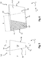
Figur 5 in einer Seitenansicht eines der Brandschutzelemente ausFigur 1 , -
Figur 6 das Brandschutzelement ausFigur 5 in einer perspektivischen Ansicht, -
Figur 7 in einer Seitenansicht eine weitere Ausführungsform eines Brandschutzelements, und -
Figur 8 das Brandschutzelement ausFigur 7 in einer perspektivischen Ansicht. - In
Figur 1 ist eine Baugruppe 10 mit einem Profilblech 12 gezeigt, das zur Bildung von Mauern oder Decken vorgesehen ist. - Das Profilblech 12 umfasst mehrere Sicken 14, die sich senkrecht von der Blechvorderseite 16 über die Blechrückseite 18 hinaus erstrecken, d.h., die Sicken 14 stehen von der Blechrückseite 18 ab. Die Blechvorderseite 16 ist hierbei als Außenseite vorgesehen, die von der durch das Profilblech 12 gebildeten Wand oder Decke in den entsprechenden Raum weist.
- Die Sicken 14 erstrecken sich in gleichmäßigen Abständen D sowie parallel zu den Breitseiten 20, 21 des Profilblechs 12 über die gesamte Breite L des Profilblechs 12 und bilden auf diese Weise die Profilierung 22 des Profilblechs 12.
- An den Breitseiten 20, 21 endet das Profilblech 12 in jeweils einer teilweise ausgebildeten Sicke 24, 25, die dazu vorgesehen ist, weitere Profilbleche 12 mit einer entsprechenden teilweise ausgebildeten Sicke 24, 25 mit dem Profilblech 12 zu verbinden. Auf diese Weise können Wände oder Decken aus mehreren miteinander verbundenen Profilblechen 12 gebildet sein, die eine einheitliche Profilierung 22 aufweisen.
- Jede Sicke 14 hat eine Öffnung 26 zu einer Flanschseite des Profilblechs 12 mit einer Breite A (siehe
Figur 2 ) und weist einen Boden 28 mit einer Breite B auf, der in einer Tiefe C parallel zur Blechrückseite 18 angeordnet ist. Ferner hat jede Sicke 14 zwei gegenüberliegende Seitenwände 29, die sich jeweils unter einem Winkel α gegenüber der Blechrückseite 18 von der Öffnung 26 bis zum Boden 28 erstrecken. - Der Winkel α beträgt weniger als 90°, das heißt, die Sicken 14 haben einen trapezförmigen sowie konstanten Querschnitt.
- Ferner bilden die Sicken 14 jeweils eine Hinterschneidung, wodurch die Profilierung 22 hinterschnitten ist.
- Die Breite A beträgt z.B. 15 mm, die Breite B beträgt z.B. 34 mm und die Tiefe C beträgt z.B. 51 mm. Alternativ können die Sicken 14 beliebig groß sein.
- Gemäß einer alternativen Ausführungsform können die Sicken 14 einen im Wesentlichen beliebigen Querschnitt aufweisen, solange sie eine Hinterschneidung bilden. Beispielsweise kann die Sicke 14 einen schwalbenschwanzförmigen Querschnitt mit einem angewinkelten Boden 28 (siehe
Figur 3 ) oder einen abschnittsweisen runden Querschnitt aufweisen (sieheFigur 4 ), wodurch die Sicken 14 Ω-förmige Abschnitte im Profilblech 12 bilden. - In einer weiteren alternativen Ausführungsform können die Sicken 14 im Wesentlichen beliebig zueinander angeordnet sein und/oder sich unter einem beliebigen Winkel über einen Teil des Profilblechs 12 oder das gesamte Profilblech 12 erstrecken.
- Ferner kann das Profilblech 12 Sicken 14 mit verschiedenen und/oder nicht konstanten Querschnitten aufweisen.
- Das Profilblech 12 besteht aus Metall. Alternativ kann das Profilblech 12 aus einem beliebigen Material gebildet sein, wobei Materialien mit einer hohen Festigkeit und/oder guten Brandschutzeigenschaften bevorzugt sind.
- Um die Brandschutzeigenschaften des Profilblechs 12 zu verbessern, umfasst die Baugruppe 10 ferner Brandschutzelemente 30, die jeweils in einer Sicke 14 angeordnet sind (siehe
Figur 1 ). In der dargestellten Ausführungsform sind zwei der drei Sicken 14 mit Brandschutzelementen 30 gefüllt. Alternativ können eine beliebige Anzahl der Sicken 14 mit einem oder mehreren Brandschutzelementen 30 gefüllt sein. Vorzugsweise sind jedoch alle Sicken 14 mit einem oder mehreren Brandschutzelement 30 gefüllt, insbesondere auch die teilweise ausgebildeten Sicken 24, 25, unabhängig davon, ob sie mit einer weiteren teilweise ausgebildeten Sicke 24, 25 eine vollständige Sicke 14 bilden oder nicht. - Die mit Brandschutzelementen 30 gefüllten Sicken 14 sind dabei vollständig durch mehrere nebeneinander angeordnete Brandschutzelemente 30 gefüllt.
- In einer alternativen Ausführungsform kann in einer Sicke 14 auch ein einzelnes Brandschutzelement 30 vorgesehen sein, dass sich vorzugsweise über die gesamte Breite L der Sicke 14 erstreckt.
- Ferner sind die Brandschutzelemente 30 vollständig in der Sicke 14 aufgenommen und stehen somit nicht über die Blechvorderseite 16 hervor.
- Die Brandschutzelemente 30 sind aus einem Material auf Basis von Polyurethan gebildet, beispielsweise aus einem Polyurethanschaumstoff, und sind staub- und gegebenenfalls faserfrei.
- Jedes der Brandschutzelemente 30 kann ferner zu einem Teil aus einem intumeszierenden Material gebildet sein.
- Gemäß einer Ausführungsform kann das Brandschutzelement 30 eine Verstärkungseinlage aufweisen, die beispielsweise durch eine Matte, ein Gitter oder ein Gewebe gebildet ist und vorzugsweise aus Metall, Streckmetall, Glasfasern, Basaltfasern, Kohlenstofffasern oder Keramikfasern besteht.
- In
Figur 6 ist eines der Brandschutzelemente 30 gezeigt. Das Brandschutzelement 30 ist ein Formteil mit einer Frontfläche 32 und einer entgegengesetzt angeordneten parallelen Rückfläche 34, sowie zwei zueinander entgegengesetzt angeordneten Seitenflächen 36, 37 und zwei zueinander entgegengesetzt angeordneten parallelen Stirnflächen 38, 39. - Das Brandschutzelement 30 hat einen konstanten trapezförmigen Querschnitt, der im vorliegenden Fall der Stirnfläche 38 entspricht, und erstreckt sich senkrecht zu diesem in axialer Richtung R. Die axiale Richtung R entspricht hierbei der Richtung, in die sich die Sicken 14 erstrecken.
- Die Frontfläche 32 hat eine Breite X1 von z.B. 15 mm und die Rückfläche 34 hat ein Breite X2 von z.B. 34 mm. Die Höhe Y des Brandschutzelements 30 beträgt z.B. 51 mm. Somit entspricht der Querschnitt des Brandschutzelements 30 dem Querschnitt der Sicke 14.
- Alternativ kann der Querschnitt des Brandschutzelements 30 zumindest abschnittsweise größer als der Querschnitt der Sicke 14 sein, wodurch das Brandschutzelement 30 ein Übermaß gegenüber den Innenabmessungen der Sicke 14 hat und damit in der Sicke 14 mittels einer Presspassung gehalten wird.
- In einer alternativen Ausführungsform kann das Brandschutzelement 30 ein Formteil mit im Wesentlichen beliebiger Form und Größe sein. Insbesondere kann der Querschnitt nicht konstant sein und/oder das Brandschutzelement 30 kann sich unter einem Winkel zum Querschnitt erstrecken, der nicht 90° beträgt. Vorzugsweise entspricht die Form des Querschnitts des Brandschutzelements 30 genau oder im Wesentlichen der Form des Querschnitts der Sicke 14, um eine möglichst gute Füllung der Sicke 14 gewährleisten zu können.
- In
Figur 8 ist eine solche alternative Ausführungsform des Brandschutzelements 30 gezeigt, bei der das Brandschutzelement 30 einen rechteckigen Querschnitt hat (sieheFigur 7 ) und als quaderförmiges Formteil ausgebildet ist. - Das quaderförmige Brandschutzelement 30 hat eine Frontfläche 32 und eine entgegengesetzt angeordnete parallele Rückfläche 34, sowie zwei zueinander entgegengesetzt angeordnete parallele Seitenflächen 36, 37 und zwei zueinander entgegengesetzt angeordnete parallele Stirnflächen 38, 39.
- Die Stirnfläche 38 hat eine Breite X1 von z.B. 35 mm und eine Höhe Y von z.B. 65 mm.
- In beiden Ausführungsformen (keilförmig und quaderförmig) hat das Brandschutzelement 30 eine Länge Z von z.B. 50 mm. Alternativ kann die Länge Z im Wesentlichen beliebig groß sein. Insbesondere kann die Länge Z der Breite L des Profilblechs 12 entsprechen, sodass jede Sicke 14 mit einem einzelnen Brandschutzelement 30 über die gesamte Breite L gefüllt werden kann. Gemäß einer weiteren Ausführungsform kann das Brandschutzelement 30 als Endlosmaterial ausgebildet sein, wodurch Abschnitte mit einer gewünschten Länge Z abgetrennt werden können und somit weniger Abfall anfällt.
- Das Profilblech 12 und die Brandschutzelemente 30 werden getrennt voneinander gefertigt, d.h. die Brandschutzelemente 30 müssen in die Sicken 14 eingesetzt werden, um die Baugruppe 10 zu bilden.
- Um das Einsetzen der Brandschutzelemente 30 in die Sicken 14 zu erleichtern, können die Brandschutzelemente 30 mit geringer Kraft, beispielsweise mit 10 N, zusammengedrückt werden, d.h. die Brandschutzelemente 30 sind komprimierbar.
- Die Brandschutzelemente 30 sind dabei in jeder Richtung um bis zu 75% komprimierbar.
- Ferner sind die Brandschutzelemente 30 elastisch, sodass sie nach einer Verformung wieder in ihre Ausgangsform streben.
- Hierdurch ist es möglich, Brandschutzelemente 30 mit einem Übermaß in die Sicken 14 einzusetzen. Ferner können die Brandschutzelemente 30 auf diese Weise durch die Öffnung 26 in die Sicken 14 eingesetzt werden, das bedeutet, auch noch nachdem das Profilblech 12 in einer Mauer oder Decke verbaut wurde, solange die Öffnungen 26 zugänglich sind.
- Alternativ können die Brandschutzelemente 30 um einen geringeren Wert komprimierbar sein, insbesondere wenn die Breite B des Bodens 28 der Sicke 14 nicht deutlich größer ist als die Breite A der Öffnung 26. Vorzugsweise sind die Brandschutzelemente 30 zumindest soweit komprimierbar, dass die Breite X2 der Rückfläche 34 maximal so groß ist wie die Breite A der Öffnung 26. Beispielsweise können die Brandschutzelemente 30 in einer alternativen Ausführungsform um mindestens 25% oder um mindestens 50% komprimierbar sein.
- In einer alternativen Ausführungsform können die Brandschutzelemente 30 um mehr als 75% komprimierbar sein.
- Ferner kann in einer weiteren alternativen Ausführungsform vorgesehen sein, dass die Brandschutzelemente 30 nicht in jeder Richtung, sondern nur in bestimmte Richtungen komprimierbar sind. Insbesondere sind die Brandschutzelemente 30 zumindest in einer Richtung quer zur axialen Richtung R komprimierbar, vorzugsweise in einer Richtung, die senkrecht zur axialen Richtung R sowie parallel zur Frontfläche 32 steht.
- Somit lässt sich ein Brandschutzelement 30 in eine Sicke 14 einsetzen, indem das Brandschutzelement 30 an den Seitenflächen 36, 37 zusammengedrückt und mit der Rückfläche 34 voran durch die Öffnung 26 geschoben wird. Hierbei berühren die Seitenflächen 36, 37 üblicherweise das Profilblech 12.
- Um die Reibung zu verringern und damit das Einsetzen des Brandschutzelements 30 zu erleichtern, sind die Seitenflächen 36, 37 sowie die Frontfläche 32 des Brandschutzelements 30 vollständig durch eine einstückige Folie 40 gebildet. In diesem Fall bildet das Formteil aus einem Material auf Basis von Polyurethan den Kern 42 des Brandschutzelements 30, der abschnittsweise von der Folie 40 bedeckt ist. Alternativ kann die Folie 40 nicht einstückig sein, das heißt, die Folie 40 besteht aus mehreren Stücken, die verschiedene Abschnitte der Folie 40 bilden.
- Die Folie 40 kann aus einem beliebigen Material bestehen, beispielsweise Kunststoff, Metall, Glasfasern, Basaltfasern, Kohlenstofffasern und/oder Keramikfasern. Vorzugsweise weist das Material einen niedrigen Reibungskoeffizienten auf, beispielsweise mit einem Wert von weniger als 0,5.
- Ferner kann das Brandschutzelement 30 auf einer beliebigen Anzahl von Seiten von der Folie 40 bedeckt sein. Hierbei können die entsprechenden Seiten vollständig oder auch nur teilweise von der Folie 40 bedeckt sein.
- Vorzugsweise erstreckt sich die Folie 40 in der Umfangsrichtung U (siehe
Figur 5 ), die senkrecht zur axialen Richtung R steht, wobei die Stirnflächen 38, 39 freiliegen. Somit ist die Folie 40 nur an den Seiten des Brandschutzelements 30 vorgesehen, die an das Profilblech 12 oder die Öffnung 26 angrenzen bzw. diesen gegenüberliegen. - Die Folie 40 ist insbesondere stoffschlüssig am Kern 42 befestigt.
- Auf diese Weise wird ein Brandschutzelement 30 bereitgestellt, mittels dem sich die Brandschutzeigenschaften eines Profilblechs 12 verbessern lassen, indem zumindest eine Sicke 14 des Profilblechs 12 mit wenigstens einem Brandschutzelement 30 zumindest teilweise gefüllt wird.
- Indem die Brandschutzelemente 30 als Formteile vorgesehen sind, können diese einfach und in einem Stück in die Sicken 14 eingesetzt werden. Somit kann die Bestückung des Profilblechs 12 erfolgen, ohne dass dabei Schmutz, Staub oder Chemikalien freigesetzt werden.
- Die Erfindung ist nicht auf die gezeigten Ausführungsformen beschränkt. Insbesondere können einzelne Merkmale einer Ausführungsform unabhängig von den anderen Merkmalen der entsprechenden Ausführungsform in einer weiteren erfindungsgemäßen Ausführungsform enthalten sein, d.h. die beschriebenen Merkmale sind beliebig kombinierbar, innerhalb der durch die Ansprüche definierten Grenzen.
Claims (12)
- Baugruppe (10) umfassend ein Profilblech (12) zur Bildung von Mauern oder Decken sowie zumindest ein Brandschutz- und/oder Schallschutzelement (30), wobei das Profilblech (12) eine Profilierung (22) mit zumindest einer Sicke (14) hat, die von einer Blechseite (16) ausgeht und zu ihrem Boden (28) hin breiter wird, so dass eine Hinterschneidung gebildet ist, wobei das Brandschutz- und/oder Schallschutzelement (30) in der Sicke (14) angeordnet ist, dadurch gekennzeichnet, dass das Brandschutz- und/oder Schallschutzelement (30) ein Formteil ist, das aus einem Material gebildet ist, das Polyurethan umfasst, wobei das Brandschutz- und/oder Schallschutzelement (30) einen Kern (42) hat, der aus einem Material gebildet ist, das Polyurethan umfasst, und der zumindest teilweise mit einer Folie (40) umhüllt ist.
- Baugruppe nach Anspruch 1, dadurch gekennzeichnet, dass die Sicke (14) einen trapezförmigen Querschnitt hat.
- Baugruppe nach einem der vorhergehenden Ansprüche, dadurch gekennzeichnet, dass die Sicke (14) im Wesentlichen vollständig mit dem zumindest einen Brandschutz- und/oder Schallschutzelement (30) gefüllt ist.
- Baugruppe nach einem der vorhergehenden Ansprüche, dadurch gekennzeichnet, dass das Brandschutz- und/oder Schallschutzelement (30) im Wesentlichen vollständig in der Sicke (14) aufgenommen ist.
- Baugruppe nach einem der vorhergehenden Ansprüche, dadurch gekennzeichnet, dass die Sicke (14) über die gesamte Breite (L) des Profilblechs (12) verläuft.
- Baugruppe (10) nach einem der vorhergehenden Ansprüche, dadurch gekennzeichnet, dass das Brandschutz- und/oder Schallschutzelement (30) ein intumeszierendes Material umfasst.
- Baugruppe nach einem der vorhergehenden Ansprüche, dadurch gekennzeichnet, dass das Brandschutz- und/oder Schallschutzelement (30) aus einem staub- und gegebenenfalls faserfreien Material gebildet ist.
- Baugruppe nach einem der vorhergehenden Ansprüche, dadurch gekennzeichnet, dass sich die Folie (40) in einer Umfangsrichtung (U) erstreckt, die senkrecht zur Richtung (R) der axialen Erstreckung des Brandschutz- und/oder Schallschutzelements (30) steht.
- Baugruppe nach Anspruch 8, dadurch gekennzeichnet, dass die Stirnflächen (38, 39) des Kerns (42) freiliegen.
- Baugruppe nach einem der vorhergehenden Ansprüche, dadurch gekennzeichnet, dass das Brandschutz- und/oder Schallschutzelement (30) ein langgestrecktes Profilteil mit einem insbesondere konstanten Querschnitt ist.
- Baugruppe nach Anspruch 10, dadurch gekennzeichnet, dass die Form des Querschnitts des Brandschutz- und/oder Schallschutzelements (30) der Form des Querschnitts der Sicke (14) entspricht, insbesondere wobei das Brandschutz- und/oder Schallschutzelement (30) mit einem Übermaß gegenüber den Innenabmessungen der Sicke (14) ausgebildet ist.
- Baugruppe nach einem der vorhergehenden Ansprüche, dadurch gekennzeichnet, dass das Brandschutz- und/oder Schallschutzelement (30) in zumindest einer Richtung komprimierbar ist, vorzugsweise in einer Richtung quer zur axialen Erstreckung (R) des Brandschutz- und/oder Schallschutzelements (30), insbesondere um mindestens 25%, vorzugsweise um mindestens 50%, bevorzugt um mindestens 75%.
Priority Applications (1)
| Application Number | Priority Date | Filing Date | Title |
|---|---|---|---|
| EP17195088.4A EP3467230B1 (de) | 2017-10-06 | 2017-10-06 | Baugruppe mit profilblech und brandschutz- und oder schallschutzelement sowie brandschutz- und /oder schallschutzelement zur bildung einer baugruppe |
Applications Claiming Priority (1)
| Application Number | Priority Date | Filing Date | Title |
|---|---|---|---|
| EP17195088.4A EP3467230B1 (de) | 2017-10-06 | 2017-10-06 | Baugruppe mit profilblech und brandschutz- und oder schallschutzelement sowie brandschutz- und /oder schallschutzelement zur bildung einer baugruppe |
Publications (2)
| Publication Number | Publication Date |
|---|---|
| EP3467230A1 EP3467230A1 (de) | 2019-04-10 |
| EP3467230B1 true EP3467230B1 (de) | 2020-08-12 |
Family
ID=60051371
Family Applications (1)
| Application Number | Title | Priority Date | Filing Date |
|---|---|---|---|
| EP17195088.4A Active EP3467230B1 (de) | 2017-10-06 | 2017-10-06 | Baugruppe mit profilblech und brandschutz- und oder schallschutzelement sowie brandschutz- und /oder schallschutzelement zur bildung einer baugruppe |
Country Status (1)
| Country | Link |
|---|---|
| EP (1) | EP3467230B1 (de) |
Families Citing this family (3)
| Publication number | Priority date | Publication date | Assignee | Title |
|---|---|---|---|---|
| USD949442S1 (en) * | 2019-04-23 | 2022-04-19 | Epic Metals Corporation | Roofing deck |
| EP3786380A1 (de) * | 2019-08-27 | 2021-03-03 | Vesterby Træteknik A/S | Brandschutz- und akustikbauplatte sowie brandschutz- und akustikbauplattensystem |
| US20240426101A1 (en) * | 2023-06-23 | 2024-12-26 | Personal Apportion Dwellings LLC | Residential community construction |
Family Cites Families (17)
| Publication number | Priority date | Publication date | Assignee | Title |
|---|---|---|---|---|
| US2106390A (en) * | 1936-06-02 | 1938-01-25 | Norman E Crane | Building board |
| US3041682A (en) * | 1957-05-21 | 1962-07-03 | Sterling W Alderfer | Foamed sealing strip products |
| US3466831A (en) * | 1968-05-06 | 1969-09-16 | Moncrief Lenoir Mfg Co | Sandwich-type building panel |
| SE436505B (sv) * | 1981-09-24 | 1984-12-17 | Graenges Aluminium Ab | Laminerat profilelement for byggnader och forfarande for tillverkning av sadant |
| DE3409897A1 (de) * | 1984-03-17 | 1985-09-19 | August Wilhelm Andernach Kg | Brandschutzbahn mit dampfsperre |
| US4747247A (en) * | 1986-09-19 | 1988-05-31 | The Dow Chemical Company | Roof system |
| US5317852A (en) * | 1991-11-27 | 1994-06-07 | Howland Koert R | Roof construction for leak detection |
| FR2709774A1 (fr) * | 1993-09-07 | 1995-03-17 | Faconnage Cont Acier Atel | Elément de toiture du type panneau en tôle pliée. |
| DE4410199A1 (de) * | 1994-03-24 | 1995-10-05 | Norm Amc Ag | Lüfterkappe |
| FR2779166B1 (fr) * | 1998-05-27 | 2000-07-21 | Rockwool Isolation Sa | Toiture thermiquement isolante et acoustiquement absorbante |
| DE10007977B4 (de) | 2000-02-22 | 2004-07-29 | Hilti Ag | Additivmischung zur Erhöhung der Brandfestigkeit von Kunststoff-Formkörpern, Kunststoff-Formkörper und Zweikomponentensystem zu ihrer Herstellung |
| GB2365452B (en) * | 2000-07-29 | 2003-09-24 | Environmental Seals Ltd | Fire resistant spacer |
| DE20022832U1 (de) * | 2000-10-23 | 2002-05-23 | FIBO Exclay Deutschland GmbH, 21769 Lamstedt | Schalldämmfüllkörper für Trapezbleche |
| US8567144B2 (en) * | 2004-09-14 | 2013-10-29 | Thomas L. Kelly | Low cost roof system and method of constructing the same |
| US7851048B2 (en) * | 2008-02-12 | 2010-12-14 | Milliken & Co. | Fiber reinforced core panel |
| US20090223159A1 (en) * | 2008-03-08 | 2009-09-10 | Mark Colon | Firestop block and thermal barrier system for fluted metal decks |
| EP2982809B1 (de) * | 2014-08-05 | 2017-02-01 | IWIS Insulation Waterproofing Industrial Systems S.R.L. | Integriertes System für Isolierung, Belüftung und Befestigung für ein Dach |
-
2017
- 2017-10-06 EP EP17195088.4A patent/EP3467230B1/de active Active
Non-Patent Citations (1)
| Title |
|---|
| None * |
Also Published As
| Publication number | Publication date |
|---|---|
| EP3467230A1 (de) | 2019-04-10 |
Similar Documents
| Publication | Publication Date | Title |
|---|---|---|
| EP0137105B1 (de) | Schalungselement für die Mantelbetonbauweise | |
| EP2584133B1 (de) | Verfahren zur Abdichtung bei der Fenstersanierung | |
| EP3586050B1 (de) | Brandschutzelement | |
| EP1866498A1 (de) | C-profil | |
| DE2935745C2 (de) | Lärmschutzwand | |
| EP3467230A1 (de) | Baugruppe mit profilblech und brandschutz- und oder schallschutzelement sowie brandschutz- und /oder schallschutzelement zur bildung einer baugruppe | |
| EP2960392B1 (de) | Deckenrandschalungselement | |
| EP3385466B1 (de) | Profil zur errichtung einer nicht tragenden aussenwand für gebäude, eine nicht tragende aussenwand für ein gebäude die wenigstens ein solches profil umfasst sowie ein gebäude welches eine solche nicht tragende aussenwand umfasst | |
| DE202017106075U1 (de) | Baugruppe mit Profilblech und Brandschutz- und/oder Schallschutzelement sowie Brandschutz- und/oder Schallschutzelement zur Bildung einer Baugruppe | |
| DE19548440A1 (de) | Wandelement | |
| EP2014843A2 (de) | Mauerstein mit Dämmmaterial | |
| DE10034341C2 (de) | Ziegel mit in Lochkammer eingestecktem Dämmmaterial | |
| EP0239053A2 (de) | Vorgefertigter Rolladenkasten aus aneinanderstossenden Ziegelformsteinen, sowie Verfahren zur Herstellung desselben | |
| DE202014102920U1 (de) | Deckenrandschalungselement | |
| DE102017120254B4 (de) | Winkelelement und Laibungsverkleidung mit einem Winkelelement | |
| EP3208396B1 (de) | Schienenanordnung | |
| DE202013102272U1 (de) | Schalungsstein zur Verbindung mit einer Betondecke | |
| DE202012011757U1 (de) | Isolierte Gebäudefassade | |
| DE202017107471U1 (de) | Deckenrandschalungselement | |
| DE202018100602U1 (de) | Schalungselement | |
| DE202023105151U1 (de) | Feuerfester Zwischenboden | |
| DE3045096C2 (de) | Schichtdämmplatte zum Ausfachen der Zwischenräume zwischen etwa parallel verlaufenden Balken oder Schienen | |
| EP3015612B1 (de) | Wandelement eines bauwerks mit zwei profilen und einer schaumstoffplatte | |
| DE202019100581U1 (de) | Gebäude mit einer Wand und einer auf dieser Wand aufliegenden Decke, Gebäude mit einer Wand, Bewehrungselement, Bewehrungsbauteil und Bewehrungsbaugruppe | |
| DE20317987U1 (de) | Lüftungsgitter zum Be- und/oder Entlüften eines Raumes |
Legal Events
| Date | Code | Title | Description |
|---|---|---|---|
| PUAI | Public reference made under article 153(3) epc to a published international application that has entered the european phase |
Free format text: ORIGINAL CODE: 0009012 |
|
| STAA | Information on the status of an ep patent application or granted ep patent |
Free format text: STATUS: THE APPLICATION HAS BEEN PUBLISHED |
|
| AK | Designated contracting states |
Kind code of ref document: A1 Designated state(s): AL AT BE BG CH CY CZ DE DK EE ES FI FR GB GR HR HU IE IS IT LI LT LU LV MC MK MT NL NO PL PT RO RS SE SI SK SM TR |
|
| AX | Request for extension of the european patent |
Extension state: BA ME |
|
| STAA | Information on the status of an ep patent application or granted ep patent |
Free format text: STATUS: REQUEST FOR EXAMINATION WAS MADE |
|
| 17P | Request for examination filed |
Effective date: 20191010 |
|
| RBV | Designated contracting states (corrected) |
Designated state(s): AL AT BE BG CH CY CZ DE DK EE ES FI FR GB GR HR HU IE IS IT LI LT LU LV MC MK MT NL NO PL PT RO RS SE SI SK SM TR |
|
| GRAP | Despatch of communication of intention to grant a patent |
Free format text: ORIGINAL CODE: EPIDOSNIGR1 |
|
| STAA | Information on the status of an ep patent application or granted ep patent |
Free format text: STATUS: GRANT OF PATENT IS INTENDED |
|
| RIC1 | Information provided on ipc code assigned before grant |
Ipc: E04D 3/30 20060101ALI20200511BHEP Ipc: E04C 2/34 20060101ALI20200511BHEP Ipc: E04F 13/12 20060101ALI20200511BHEP Ipc: E04D 3/35 20060101ALI20200511BHEP Ipc: E04B 1/86 20060101ALI20200511BHEP Ipc: E04B 1/84 20060101ALI20200511BHEP Ipc: E04C 2/08 20060101ALI20200511BHEP Ipc: E04C 2/32 20060101ALI20200511BHEP Ipc: E04B 1/94 20060101ALN20200511BHEP Ipc: E04C 2/292 20060101ALI20200511BHEP Ipc: E04D 13/16 20060101AFI20200511BHEP |
|
| INTG | Intention to grant announced |
Effective date: 20200527 |
|
| GRAS | Grant fee paid |
Free format text: ORIGINAL CODE: EPIDOSNIGR3 |
|
| GRAA | (expected) grant |
Free format text: ORIGINAL CODE: 0009210 |
|
| STAA | Information on the status of an ep patent application or granted ep patent |
Free format text: STATUS: THE PATENT HAS BEEN GRANTED |
|
| AK | Designated contracting states |
Kind code of ref document: B1 Designated state(s): AL AT BE BG CH CY CZ DE DK EE ES FI FR GB GR HR HU IE IS IT LI LT LU LV MC MK MT NL NO PL PT RO RS SE SI SK SM TR |
|
| REG | Reference to a national code |
Ref country code: CH Ref legal event code: EP |
|
| REG | Reference to a national code |
Ref country code: IE Ref legal event code: FG4D Free format text: LANGUAGE OF EP DOCUMENT: GERMAN |
|
| REG | Reference to a national code |
Ref country code: DE Ref legal event code: R096 Ref document number: 502017006693 Country of ref document: DE |
|
| REG | Reference to a national code |
Ref country code: NL Ref legal event code: FP |
|
| REG | Reference to a national code |
Ref country code: AT Ref legal event code: REF Ref document number: 1301684 Country of ref document: AT Kind code of ref document: T Effective date: 20200915 |
|
| REG | Reference to a national code |
Ref country code: LT Ref legal event code: MG4D |
|
| PG25 | Lapsed in a contracting state [announced via postgrant information from national office to epo] |
Ref country code: FI Free format text: LAPSE BECAUSE OF FAILURE TO SUBMIT A TRANSLATION OF THE DESCRIPTION OR TO PAY THE FEE WITHIN THE PRESCRIBED TIME-LIMIT Effective date: 20200812 Ref country code: HR Free format text: LAPSE BECAUSE OF FAILURE TO SUBMIT A TRANSLATION OF THE DESCRIPTION OR TO PAY THE FEE WITHIN THE PRESCRIBED TIME-LIMIT Effective date: 20200812 Ref country code: SE Free format text: LAPSE BECAUSE OF FAILURE TO SUBMIT A TRANSLATION OF THE DESCRIPTION OR TO PAY THE FEE WITHIN THE PRESCRIBED TIME-LIMIT Effective date: 20200812 Ref country code: NO Free format text: LAPSE BECAUSE OF FAILURE TO SUBMIT A TRANSLATION OF THE DESCRIPTION OR TO PAY THE FEE WITHIN THE PRESCRIBED TIME-LIMIT Effective date: 20201112 Ref country code: GR Free format text: LAPSE BECAUSE OF FAILURE TO SUBMIT A TRANSLATION OF THE DESCRIPTION OR TO PAY THE FEE WITHIN THE PRESCRIBED TIME-LIMIT Effective date: 20201113 Ref country code: BG Free format text: LAPSE BECAUSE OF FAILURE TO SUBMIT A TRANSLATION OF THE DESCRIPTION OR TO PAY THE FEE WITHIN THE PRESCRIBED TIME-LIMIT Effective date: 20201112 Ref country code: LT Free format text: LAPSE BECAUSE OF FAILURE TO SUBMIT A TRANSLATION OF THE DESCRIPTION OR TO PAY THE FEE WITHIN THE PRESCRIBED TIME-LIMIT Effective date: 20200812 |
|
| PG25 | Lapsed in a contracting state [announced via postgrant information from national office to epo] |
Ref country code: PL Free format text: LAPSE BECAUSE OF FAILURE TO SUBMIT A TRANSLATION OF THE DESCRIPTION OR TO PAY THE FEE WITHIN THE PRESCRIBED TIME-LIMIT Effective date: 20200812 Ref country code: RS Free format text: LAPSE BECAUSE OF FAILURE TO SUBMIT A TRANSLATION OF THE DESCRIPTION OR TO PAY THE FEE WITHIN THE PRESCRIBED TIME-LIMIT Effective date: 20200812 Ref country code: LV Free format text: LAPSE BECAUSE OF FAILURE TO SUBMIT A TRANSLATION OF THE DESCRIPTION OR TO PAY THE FEE WITHIN THE PRESCRIBED TIME-LIMIT Effective date: 20200812 Ref country code: IS Free format text: LAPSE BECAUSE OF FAILURE TO SUBMIT A TRANSLATION OF THE DESCRIPTION OR TO PAY THE FEE WITHIN THE PRESCRIBED TIME-LIMIT Effective date: 20201212 |
|
| PG25 | Lapsed in a contracting state [announced via postgrant information from national office to epo] |
Ref country code: SM Free format text: LAPSE BECAUSE OF FAILURE TO SUBMIT A TRANSLATION OF THE DESCRIPTION OR TO PAY THE FEE WITHIN THE PRESCRIBED TIME-LIMIT Effective date: 20200812 Ref country code: EE Free format text: LAPSE BECAUSE OF FAILURE TO SUBMIT A TRANSLATION OF THE DESCRIPTION OR TO PAY THE FEE WITHIN THE PRESCRIBED TIME-LIMIT Effective date: 20200812 Ref country code: RO Free format text: LAPSE BECAUSE OF FAILURE TO SUBMIT A TRANSLATION OF THE DESCRIPTION OR TO PAY THE FEE WITHIN THE PRESCRIBED TIME-LIMIT Effective date: 20200812 Ref country code: DK Free format text: LAPSE BECAUSE OF FAILURE TO SUBMIT A TRANSLATION OF THE DESCRIPTION OR TO PAY THE FEE WITHIN THE PRESCRIBED TIME-LIMIT Effective date: 20200812 Ref country code: CZ Free format text: LAPSE BECAUSE OF FAILURE TO SUBMIT A TRANSLATION OF THE DESCRIPTION OR TO PAY THE FEE WITHIN THE PRESCRIBED TIME-LIMIT Effective date: 20200812 |
|
| REG | Reference to a national code |
Ref country code: DE Ref legal event code: R097 Ref document number: 502017006693 Country of ref document: DE |
|
| PG25 | Lapsed in a contracting state [announced via postgrant information from national office to epo] |
Ref country code: ES Free format text: LAPSE BECAUSE OF FAILURE TO SUBMIT A TRANSLATION OF THE DESCRIPTION OR TO PAY THE FEE WITHIN THE PRESCRIBED TIME-LIMIT Effective date: 20200812 Ref country code: AL Free format text: LAPSE BECAUSE OF FAILURE TO SUBMIT A TRANSLATION OF THE DESCRIPTION OR TO PAY THE FEE WITHIN THE PRESCRIBED TIME-LIMIT Effective date: 20200812 |
|
| PLBE | No opposition filed within time limit |
Free format text: ORIGINAL CODE: 0009261 |
|
| STAA | Information on the status of an ep patent application or granted ep patent |
Free format text: STATUS: NO OPPOSITION FILED WITHIN TIME LIMIT |
|
| PG25 | Lapsed in a contracting state [announced via postgrant information from national office to epo] |
Ref country code: LU Free format text: LAPSE BECAUSE OF NON-PAYMENT OF DUE FEES Effective date: 20201006 Ref country code: MC Free format text: LAPSE BECAUSE OF FAILURE TO SUBMIT A TRANSLATION OF THE DESCRIPTION OR TO PAY THE FEE WITHIN THE PRESCRIBED TIME-LIMIT Effective date: 20200812 Ref country code: SK Free format text: LAPSE BECAUSE OF FAILURE TO SUBMIT A TRANSLATION OF THE DESCRIPTION OR TO PAY THE FEE WITHIN THE PRESCRIBED TIME-LIMIT Effective date: 20200812 |
|
| REG | Reference to a national code |
Ref country code: BE Ref legal event code: MM Effective date: 20201031 |
|
| 26N | No opposition filed |
Effective date: 20210514 |
|
| PG25 | Lapsed in a contracting state [announced via postgrant information from national office to epo] |
Ref country code: IT Free format text: LAPSE BECAUSE OF FAILURE TO SUBMIT A TRANSLATION OF THE DESCRIPTION OR TO PAY THE FEE WITHIN THE PRESCRIBED TIME-LIMIT Effective date: 20200812 |
|
| PG25 | Lapsed in a contracting state [announced via postgrant information from national office to epo] |
Ref country code: SI Free format text: LAPSE BECAUSE OF FAILURE TO SUBMIT A TRANSLATION OF THE DESCRIPTION OR TO PAY THE FEE WITHIN THE PRESCRIBED TIME-LIMIT Effective date: 20200812 Ref country code: BE Free format text: LAPSE BECAUSE OF NON-PAYMENT OF DUE FEES Effective date: 20201031 |
|
| PG25 | Lapsed in a contracting state [announced via postgrant information from national office to epo] |
Ref country code: IE Free format text: LAPSE BECAUSE OF NON-PAYMENT OF DUE FEES Effective date: 20201006 |
|
| PG25 | Lapsed in a contracting state [announced via postgrant information from national office to epo] |
Ref country code: TR Free format text: LAPSE BECAUSE OF FAILURE TO SUBMIT A TRANSLATION OF THE DESCRIPTION OR TO PAY THE FEE WITHIN THE PRESCRIBED TIME-LIMIT Effective date: 20200812 Ref country code: MT Free format text: LAPSE BECAUSE OF FAILURE TO SUBMIT A TRANSLATION OF THE DESCRIPTION OR TO PAY THE FEE WITHIN THE PRESCRIBED TIME-LIMIT Effective date: 20200812 Ref country code: CY Free format text: LAPSE BECAUSE OF FAILURE TO SUBMIT A TRANSLATION OF THE DESCRIPTION OR TO PAY THE FEE WITHIN THE PRESCRIBED TIME-LIMIT Effective date: 20200812 |
|
| PG25 | Lapsed in a contracting state [announced via postgrant information from national office to epo] |
Ref country code: MK Free format text: LAPSE BECAUSE OF FAILURE TO SUBMIT A TRANSLATION OF THE DESCRIPTION OR TO PAY THE FEE WITHIN THE PRESCRIBED TIME-LIMIT Effective date: 20200812 |
|
| PG25 | Lapsed in a contracting state [announced via postgrant information from national office to epo] |
Ref country code: PT Free format text: LAPSE BECAUSE OF FAILURE TO SUBMIT A TRANSLATION OF THE DESCRIPTION OR TO PAY THE FEE WITHIN THE PRESCRIBED TIME-LIMIT Effective date: 20200812 |
|
| REG | Reference to a national code |
Ref country code: CH Ref legal event code: U11 Free format text: ST27 STATUS EVENT CODE: U-0-0-U10-U11 (AS PROVIDED BY THE NATIONAL OFFICE) Effective date: 20251101 |
|
| PGFP | Annual fee paid to national office [announced via postgrant information from national office to epo] |
Ref country code: NL Payment date: 20251021 Year of fee payment: 9 |
|
| PGFP | Annual fee paid to national office [announced via postgrant information from national office to epo] |
Ref country code: DE Payment date: 20251021 Year of fee payment: 9 |
|
| PGFP | Annual fee paid to national office [announced via postgrant information from national office to epo] |
Ref country code: GB Payment date: 20251022 Year of fee payment: 9 |
|
| PGFP | Annual fee paid to national office [announced via postgrant information from national office to epo] |
Ref country code: AT Payment date: 20251022 Year of fee payment: 9 |
|
| PGFP | Annual fee paid to national office [announced via postgrant information from national office to epo] |
Ref country code: FR Payment date: 20251030 Year of fee payment: 9 |
|
| PGFP | Annual fee paid to national office [announced via postgrant information from national office to epo] |
Ref country code: CH Payment date: 20251101 Year of fee payment: 9 |