EP3466864B1 - Kran - Google Patents
Kran Download PDFInfo
- Publication number
- EP3466864B1 EP3466864B1 EP18020406.7A EP18020406A EP3466864B1 EP 3466864 B1 EP3466864 B1 EP 3466864B1 EP 18020406 A EP18020406 A EP 18020406A EP 3466864 B1 EP3466864 B1 EP 3466864B1
- Authority
- EP
- European Patent Office
- Prior art keywords
- extension
- extensions
- assigned
- program
- control device
- Prior art date
- Legal status (The legal status is an assumption and is not a legal conclusion. Google has not performed a legal analysis and makes no representation as to the accuracy of the status listed.)
- Active
Links
Images
Classifications
-
- B—PERFORMING OPERATIONS; TRANSPORTING
- B66—HOISTING; LIFTING; HAULING
- B66C—CRANES; LOAD-ENGAGING ELEMENTS OR DEVICES FOR CRANES, CAPSTANS, WINCHES, OR TACKLES
- B66C23/00—Cranes comprising essentially a beam, boom, or triangular structure acting as a cantilever and mounted for translatory of swinging movements in vertical or horizontal planes or a combination of such movements, e.g. jib-cranes, derricks, tower cranes
- B66C23/62—Constructional features or details
- B66C23/64—Jibs
- B66C23/70—Jibs constructed of sections adapted to be assembled to form jibs or various lengths
- B66C23/701—Jibs constructed of sections adapted to be assembled to form jibs or various lengths telescopic
- B66C23/705—Jibs constructed of sections adapted to be assembled to form jibs or various lengths telescopic telescoped by hydraulic jacks
-
- B—PERFORMING OPERATIONS; TRANSPORTING
- B66—HOISTING; LIFTING; HAULING
- B66C—CRANES; LOAD-ENGAGING ELEMENTS OR DEVICES FOR CRANES, CAPSTANS, WINCHES, OR TACKLES
- B66C2700/00—Cranes
- B66C2700/03—Cranes with arms or jibs; Multiple cranes
- B66C2700/0392—Movement of the crane arm; Coupling of the crane arm with the counterweights; Safety devices for the movement of the arm
Definitions
- the invention relates to a crane, in particular a heavy-duty crane, with a frame on which a stand that can be rotated about a stationary axis is arranged, on which a telescoping boom that can be pivoted about a horizontal axis is accommodated and that has several extensions that can be displaced one within the other in the axial direction , which can be extended and retracted by means of a hydraulic drive device, with the telescoping boom being assigned a path measuring device which measures its extension length and which is connected to an input of a control device assigned to the hydraulic drive device, into which the desired extension length of the boom can be entered, with each desired boom length, all extensions can be extended by a respectively assigned part of their maximum extension length.
- A1 removable crane can be extended by a respectively associated part of their maximum extension length for any desired boom length. However, all extensions are extended at the same time.
- the DE 694 17 228 T2 shows a crane boom in which each extension is assigned its own hydraulic cylinder arrangement. However, the individual hydraulic cylinder assemblies are actuated simultaneously, so that too the individual extensions are extended simultaneously.
- the EP 2 388 228 B1 describes a control device for a telescoping crane arm, whereby, among other things, the individual extensions are to be extended sequentially. However, there is no indication that the individual extensions are to be ejected one after the other, starting with the lowest extension.
- DE 39 11 729 A1 discloses a boom for a crane, with each extension being assigned its own correspondingly strong hydraulic cylinder arrangement which can be actuated independently of the hydraulic cylinder arrangements assigned to the other extensions.
- each extension is assigned its own, correspondingly powerful hydraulic cylinder arrangement, which can be actuated independently of the hydraulic cylinder arrangements assigned to the other extensions, and that an extension program is stored in the control device, which is designed in such a way that all extensions are each individually and nacheinader extendable and contains a sequential circuit, according to which the extension of the boom begins with the extension of the bottom extension and is successively continued upwards.
- all extensions can be extended individually one after the other by an associated part of their maximum extension length, particularly good stability of the jib when extended is achieved and thus optimum use of the possibilities of the crane according to the invention is ensured. Since the actuation of the individual extensions begins with the extension of the bottom extension and is successively continued upwards from here, there is advantageously a very obvious extension sequence, which is based on the strength of the individual extensions to the effect that the strongest extension is actuated is started.
- the hydraulic cylinders of the hydraulic cylinder arrangements assigned to the extensions are expediently designed as double-acting cylinders with two connections for hydraulic lines, each of which is assigned a valve that can be controlled by means of the control device, which is expediently designed as a multi-way valve with an inlet, outlet and pressure maintenance function.
- the ejection movement of an ejection begins ahead of the stop of the respective preceding ejection.
- a practically uninterrupted lengthening of the boom and thus a comparatively short total time for lengthening the boom can be achieved.
- the path measuring device can be expediently arranged inside the boom, the extensions of which are advantageously designed as hollow profile sections. This results in a protected, compact arrangement.
- the displacement measuring device can expediently have a cable that can be unwound from a drum that interacts with a rotation angle measuring device and that is fastened to the uppermost extension. This results in a robust, mechanical design of the path measuring device, which nonetheless delivers a high degree of accuracy.
- a further advantageous measure can be that the control device is assigned an input device designed as a remote control, by means of which the desired length of the boom can be entered, the desired program can be selected and the hydraulic drive device and the control device can be activated.
- the remote control increases the ease of use and ensures reliable monitoring and observation of the crane or its boom from the outside.
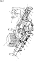
- the single figure of the drawing described below contains a view of a crane according to the invention with a schematic representation of the actuating device associated with the telescoping boom.
- the main field of application of the invention are so-called heavy-duty cranes, which are loaded onto a transport vehicle for transport over a longer distance and are unloaded from it at the place of use and can be rolled or moved there with their own running gear.
- the crane shown in the drawing has a bed-shaped frame 1, which is accommodated on rollers 2, which can be provided with heavy-duty tires, and can therefore be rolled.
- the frame 1 is provided with the example shown telescoping support beam 3, which is pivotally mounted in the frame corners about a stationary axis on the frame 1 and on are provided at their free end with a support foot 4 which can be placed on the ground and which can be extended by means of an associated hydraulic cylinder or can be formed by such a cylinder.
- a stand 6 Arranged on the frame 1 is a stand 6 that can be rotated about a stationary axis via a slewing ring 5, on which a ballast arrangement 7 is suspended on the one hand and on the other hand a carriage 8 that can be swiveled up and down about a horizontal axis is pivotally mounted, on which in turn the lower end of a telescopic boom 9 is mounted up and down around a horizontal axis. Hydraulic cylinders 10 are provided for rotating the stand 6 and for pivoting the carriage 8 and the boom 9 .
- the telescoping boom 9 consists of a plurality of telescopically arranged sections, expediently formed by hollow profile sections, with a clear width that decreases from section to section.
- the lowermost section which has the greatest clear width, is accommodated on the carriage 8 such that it can pivot.
- the other sections are designed as extensions that can be extended and retracted by means of a hydraulic drive device.
- five extensions 12 that can be extended from the lower section 11 are provided, each of which can be moved individually by means of an associated, correspondingly powerful hydraulic cylinder arrangement.
- One hydraulic cylinder 13 or a plurality of parallel hydraulic cylinders 13 can be provided in each case to form the hydraulic cylinder arrangement assigned to the extensions 12 .
- a hydraulic cylinder 13 is assigned to each of the two uppermost extensions 12 and two parallel hydraulic cylinders 13 are assigned to each of the extensions 12 that follow downwards. In the example shown, these engage with their piston rods on the associated extension 12 and are supported with their cylinder unit on the respective preceding extension 12 or section 11 .
- the lower section 11 and the extensions 12 each contain a driver and support bracket 14 which is provided at their front end and protrudes on the circumferential side.
- the crane To supply all hydraulic units with pressure oil, the crane is equipped with a the necessary pumps, drives and tanks, etc. containing supply station 15, indicated only by a rectangular box, which are connected to the associated hydraulic units via suitable hydraulic lines 16 functioning as supply or disposal lines.
- suitable hydraulic lines 16 functioning as supply or disposal lines.
- the lines associated with the other hydraulic units are only indicated by the outlets and inlets of the supply station 15 .
- the hydraulic cylinders 13 assigned to the extensions 12 are each designed as double-acting cylinders, each of which has a lower and an upper connection for an assigned hydraulic line 16 .
- Each connection is assigned a valve 17, which is designed as a controllable multi-way valve and can therefore function as an inlet, outlet and pressure-retaining valve.
- a control device 18 is provided which is also only indicated by a rectangular box and can be operated by means of an assigned remote control device 19 .
- the control device 18 is connected via signal lines 20 to the valves 17 assigned to the hydraulic cylinders 13 and designed as multi-way valves.
- the hydraulic cylinders 13 are controlled in such a way that all extensions 12 are extended individually one after the other by an assigned, preferably equal, amount.
- the boom 9 is extended to a fraction of the maximum length, this corresponds to the corresponding fraction of the maximum extended length of each extension 12.
- the extension of the boom 9 starts with the extension of the bottom extension 12 and is then from extension to extension up to top extension 12 continued.
- an extension program 21 symbolically indicated in the drawing is stored in the control device 18, which calculates the extension lengths of the individual extensions 12 from a desired length of the boom 9 that can be entered using the remote control 19 and controls the valves 17 accordingly.
- the control takes place in such a way that each extension 12 is extended individually by the same distance, which corresponds to the maximum extension length of the extensions 12 with the maximum boom length and a corresponding partial amount of the maximum extension length with a smaller boom length.
- the extension program 21 specifies the order in which the extensions 12 are individually extended one after the other, starting with the lowest, strongest extension 12 and then proceeding successively from extension to extension upwards.
- the exit program 21 therefore contains a corresponding sequential circuit.
- the sequential circuit on which the extension program 21 is based can be designed in such a way that the extension process of the extensions 12 following the first extended extension 12 takes place ahead of the stop of the extension movement of the preceding extension 12 in each case.
- This lead can be about 1% of the maximum extension length, which means that if, for example, each extension is extended by 20% of its maximum extension length, the extension movement of the next extension begins when the previous extension 12 has reached 19%. The same applies, of course, vice versa in the case of a shortening of the boom 9.
- the control device 18 calculates the extension distance of the individual extensions 12 from the desired length of the boom 9 that has been entered.
- a path measuring device is provided in the example shown, which permanently detects the reached length of the boom 9 and corresponding Outputs signals to the control device 18, as indicated by a signal line 22.
- the distance measuring device shown consists of a cable 23, etc., which is fastened on the one hand to the uppermost extension 12 and on the other hand can be unwound from a drum 24, which interacts with a rotation angle measuring device, the output of which transmits corresponding signals to the control device 18 via the signal line 22.
- the boom sections 11 on which the boom 9 is based are expediently designed as hollow profile sections, so that the position measuring device can be placed inside the boom 9, as indicated by broken lines in the drawing.
- the hollow profile sections on which the boom sections 11 are based expediently have a cross section derived from a rectangle or square, so that reliable longitudinal guidance and reliable mounting with comparatively little play is possible in the area of each side.
- a manual control program 25 which is superimposed on the extension program 21 and is also indicated symbolically in the drawing, is provided in the control device 18, which allows manual activation of the hydraulic cylinder arrangement of at least one Ejection enabled.
- the remote control 19 therefore enables a program selection in addition to entering the desired boom length and activating the supply device 15 and control device 18 .
- the remote control device 19 can also be provided with a screen for displaying the current operating states of the boom 9 or the other aggregates of the crane that can be controlled with it.
Landscapes
- Engineering & Computer Science (AREA)
- Mechanical Engineering (AREA)
- Jib Cranes (AREA)
Applications Claiming Priority (1)
| Application Number | Priority Date | Filing Date | Title |
|---|---|---|---|
| DE102017009183.8A DE102017009183A1 (de) | 2017-09-30 | 2017-09-30 | Kran |
Publications (2)
| Publication Number | Publication Date |
|---|---|
| EP3466864A1 EP3466864A1 (de) | 2019-04-10 |
| EP3466864B1 true EP3466864B1 (de) | 2022-05-18 |
Family
ID=63371453
Family Applications (1)
| Application Number | Title | Priority Date | Filing Date |
|---|---|---|---|
| EP18020406.7A Active EP3466864B1 (de) | 2017-09-30 | 2018-08-23 | Kran |
Country Status (5)
| Country | Link |
|---|---|
| EP (1) | EP3466864B1 (pl) |
| CN (1) | CN109592581B (pl) |
| DE (1) | DE102017009183A1 (pl) |
| DK (1) | DK3466864T3 (pl) |
| PL (1) | PL3466864T3 (pl) |
Family Cites Families (12)
| Publication number | Priority date | Publication date | Assignee | Title |
|---|---|---|---|---|
| DE3913516A1 (de) * | 1989-04-25 | 1990-10-31 | Century Ii Gmbh Mobilkrane | Vorrichtung zur messung der ausfahrlaengen von teleskopauslegerschuessen eines kranauslegers |
| DE3911729A1 (de) * | 1989-04-11 | 1990-10-18 | Century Ii Gmbh Mobilkrane | Verfahren und vorrichtung zum teleskopieren der auslegerschuesse eines mehrfachteleskopauslegerkranes |
| SE501102C2 (sv) * | 1993-04-26 | 1994-11-14 | Hiab Ab | Förlängningsbar kranarm |
| SE504463C2 (sv) * | 1995-06-08 | 1997-02-17 | Hiab Ab | Förlängningsbar arm, särskilt för kranar |
| JPH092781A (ja) * | 1995-06-19 | 1997-01-07 | Tadano Ltd | ブーム伸縮用油圧シリンダの制御装置 |
| DE19602972A1 (de) | 1996-01-27 | 1997-07-31 | Walter Biedenbach | Kran |
| JPH10194680A (ja) * | 1996-12-27 | 1998-07-28 | Komatsu Ltd | クレーンにおける各伸縮ブームの伸長量検出装置 |
| DE602005006386T2 (de) * | 2005-04-01 | 2009-05-20 | Cargotec Patenter Ab | Mehrstufiger Teleskopausleger. |
| CN201525712U (zh) * | 2009-07-29 | 2010-07-14 | 徐州徐工随车起重机有限公司 | 随车起重机伸缩臂控制装置 |
| JP4998589B2 (ja) * | 2010-05-18 | 2012-08-15 | コベルコクレーン株式会社 | ブーム伸縮段数切替制御装置 |
| CN102910534B (zh) * | 2012-10-18 | 2014-12-24 | 中国人民解放军总后勤部建筑工程研究所 | 一种用于折臂式随车起重机的直线起吊装置及其控制方法 |
| CN106006413A (zh) * | 2016-08-08 | 2016-10-12 | 中联重科股份有限公司 | 伸缩臂的液压控制回路及具有其的工程机械 |
-
2017
- 2017-09-30 DE DE102017009183.8A patent/DE102017009183A1/de not_active Withdrawn
-
2018
- 2018-08-16 CN CN201810931515.1A patent/CN109592581B/zh active Active
- 2018-08-23 PL PL18020406.7T patent/PL3466864T3/pl unknown
- 2018-08-23 DK DK18020406.7T patent/DK3466864T3/da active
- 2018-08-23 EP EP18020406.7A patent/EP3466864B1/de active Active
Also Published As
| Publication number | Publication date |
|---|---|
| RU2018129812A (ru) | 2020-02-18 |
| CN109592581B (zh) | 2021-05-28 |
| CN109592581A (zh) | 2019-04-09 |
| DE102017009183A1 (de) | 2019-04-04 |
| PL3466864T3 (pl) | 2022-09-05 |
| EP3466864A1 (de) | 2019-04-10 |
| DK3466864T3 (da) | 2022-08-01 |
Similar Documents
| Publication | Publication Date | Title |
|---|---|---|
| EP3459904B2 (de) | Flurförderzeug, hydraulisches system für ein flurförderzeug und verfahren zum betreiben eines hydraulischen systems | |
| DE2849144A1 (de) | Teleskopauslegerkran mit zusatzausleger | |
| DE69006085T2 (de) | Zwischenrohrvorpresseinrichtung. | |
| DE2601565B2 (de) | Sicherheits-Sperrvorrichtung für Stützarme eines Fahrzeuges, insbesondere eines fahrbaren Krans | |
| DE69106006T2 (de) | Hubvorrichtung. | |
| DE2252836B1 (de) | Turmdrehkran | |
| EP2895418B1 (de) | Turmdrehkran | |
| DE1634782B2 (de) | Strassenhobel | |
| DE102013011173B4 (de) | Verfahren zur Montage eines Krans sowie Anlenkschuss, Teleskopausleger und Kran | |
| DE1506519C2 (de) | Teleskopausleger | |
| EP2890627B1 (de) | Verriegelungsvorrichtung | |
| EP3466864A1 (de) | Kran | |
| AT401925B (de) | Ladekran | |
| DE1920981A1 (de) | Ein herunterklappbarer Kran mit einer aus Hydraulikzylindern bestehenden Vorrichtung zum Hochschwenken des Mastes | |
| DE19631547A1 (de) | Teleskopausleger, insbesondere für stationäre oder fahrbare Krane | |
| DE3037182C2 (de) | Vorrichtung zum mechanischen Führen einer Spritzdüse, insbesondere für das Auftragen von Spritzbeton | |
| DE19641191A1 (de) | Teleskopausleger, insbesondere für stationäre und fahrbare Krane | |
| DE3940798C2 (pl) | ||
| DE202020100268U1 (de) | Verteilermast für eine Betonpumpe und mobile Betonpumpe mit einem solchen Verteilermast | |
| DE29720972U1 (de) | Teleskopierbarer Ausleger | |
| DE102015114166B4 (de) | Fahrbarer Großmanipulator | |
| EP3943438B1 (de) | Fahrbarer kran mit teilbarem a-bock | |
| DE2660266C2 (de) | Abstützung für ein Kraftfahrzeug | |
| DE2633022B1 (de) | Teleskopier-antriebs-einrichtung eines teleskopauslegers | |
| DE3913516A1 (de) | Vorrichtung zur messung der ausfahrlaengen von teleskopauslegerschuessen eines kranauslegers |
Legal Events
| Date | Code | Title | Description |
|---|---|---|---|
| STAA | Information on the status of an ep patent application or granted ep patent |
Free format text: STATUS: UNKNOWN |
|
| PUAI | Public reference made under article 153(3) epc to a published international application that has entered the european phase |
Free format text: ORIGINAL CODE: 0009012 |
|
| STAA | Information on the status of an ep patent application or granted ep patent |
Free format text: STATUS: THE APPLICATION HAS BEEN PUBLISHED |
|
| AK | Designated contracting states |
Kind code of ref document: A1 Designated state(s): AL AT BE BG CH CY CZ DE DK EE ES FI FR GB GR HR HU IE IS IT LI LT LU LV MC MK MT NL NO PL PT RO RS SE SI SK SM TR |
|
| AX | Request for extension of the european patent |
Extension state: BA ME |
|
| STAA | Information on the status of an ep patent application or granted ep patent |
Free format text: STATUS: REQUEST FOR EXAMINATION WAS MADE |
|
| 17P | Request for examination filed |
Effective date: 20190415 |
|
| RBV | Designated contracting states (corrected) |
Designated state(s): AL AT BE BG CH CY CZ DE DK EE ES FI FR GB GR HR HU IE IS IT LI LT LU LV MC MK MT NL NO PL PT RO RS SE SI SK SM TR |
|
| GRAP | Despatch of communication of intention to grant a patent |
Free format text: ORIGINAL CODE: EPIDOSNIGR1 |
|
| STAA | Information on the status of an ep patent application or granted ep patent |
Free format text: STATUS: GRANT OF PATENT IS INTENDED |
|
| INTG | Intention to grant announced |
Effective date: 20220215 |
|
| GRAS | Grant fee paid |
Free format text: ORIGINAL CODE: EPIDOSNIGR3 |
|
| GRAA | (expected) grant |
Free format text: ORIGINAL CODE: 0009210 |
|
| STAA | Information on the status of an ep patent application or granted ep patent |
Free format text: STATUS: THE PATENT HAS BEEN GRANTED |
|
| AK | Designated contracting states |
Kind code of ref document: B1 Designated state(s): AL AT BE BG CH CY CZ DE DK EE ES FI FR GB GR HR HU IE IS IT LI LT LU LV MC MK MT NL NO PL PT RO RS SE SI SK SM TR |
|
| REG | Reference to a national code |
Ref country code: GB Ref legal event code: FG4D Free format text: NOT ENGLISH |
|
| REG | Reference to a national code |
Ref country code: CH Ref legal event code: EP |
|
| REG | Reference to a national code |
Ref country code: IE Ref legal event code: FG4D Free format text: LANGUAGE OF EP DOCUMENT: GERMAN |
|
| REG | Reference to a national code |
Ref country code: DE Ref legal event code: R096 Ref document number: 502018009689 Country of ref document: DE |
|
| REG | Reference to a national code |
Ref country code: AT Ref legal event code: REF Ref document number: 1493053 Country of ref document: AT Kind code of ref document: T Effective date: 20220615 Ref country code: NL Ref legal event code: FP |
|
| REG | Reference to a national code |
Ref country code: DK Ref legal event code: T3 Effective date: 20220726 |
|
| REG | Reference to a national code |
Ref country code: LT Ref legal event code: MG9D |
|
| PG25 | Lapsed in a contracting state [announced via postgrant information from national office to epo] |
Ref country code: SE Free format text: LAPSE BECAUSE OF FAILURE TO SUBMIT A TRANSLATION OF THE DESCRIPTION OR TO PAY THE FEE WITHIN THE PRESCRIBED TIME-LIMIT Effective date: 20220518 Ref country code: PT Free format text: LAPSE BECAUSE OF FAILURE TO SUBMIT A TRANSLATION OF THE DESCRIPTION OR TO PAY THE FEE WITHIN THE PRESCRIBED TIME-LIMIT Effective date: 20220919 Ref country code: NO Free format text: LAPSE BECAUSE OF FAILURE TO SUBMIT A TRANSLATION OF THE DESCRIPTION OR TO PAY THE FEE WITHIN THE PRESCRIBED TIME-LIMIT Effective date: 20220818 Ref country code: LT Free format text: LAPSE BECAUSE OF FAILURE TO SUBMIT A TRANSLATION OF THE DESCRIPTION OR TO PAY THE FEE WITHIN THE PRESCRIBED TIME-LIMIT Effective date: 20220518 Ref country code: HR Free format text: LAPSE BECAUSE OF FAILURE TO SUBMIT A TRANSLATION OF THE DESCRIPTION OR TO PAY THE FEE WITHIN THE PRESCRIBED TIME-LIMIT Effective date: 20220518 Ref country code: GR Free format text: LAPSE BECAUSE OF FAILURE TO SUBMIT A TRANSLATION OF THE DESCRIPTION OR TO PAY THE FEE WITHIN THE PRESCRIBED TIME-LIMIT Effective date: 20220819 Ref country code: FI Free format text: LAPSE BECAUSE OF FAILURE TO SUBMIT A TRANSLATION OF THE DESCRIPTION OR TO PAY THE FEE WITHIN THE PRESCRIBED TIME-LIMIT Effective date: 20220518 Ref country code: ES Free format text: LAPSE BECAUSE OF FAILURE TO SUBMIT A TRANSLATION OF THE DESCRIPTION OR TO PAY THE FEE WITHIN THE PRESCRIBED TIME-LIMIT Effective date: 20220518 Ref country code: BG Free format text: LAPSE BECAUSE OF FAILURE TO SUBMIT A TRANSLATION OF THE DESCRIPTION OR TO PAY THE FEE WITHIN THE PRESCRIBED TIME-LIMIT Effective date: 20220818 |
|
| PG25 | Lapsed in a contracting state [announced via postgrant information from national office to epo] |
Ref country code: RS Free format text: LAPSE BECAUSE OF FAILURE TO SUBMIT A TRANSLATION OF THE DESCRIPTION OR TO PAY THE FEE WITHIN THE PRESCRIBED TIME-LIMIT Effective date: 20220518 Ref country code: LV Free format text: LAPSE BECAUSE OF FAILURE TO SUBMIT A TRANSLATION OF THE DESCRIPTION OR TO PAY THE FEE WITHIN THE PRESCRIBED TIME-LIMIT Effective date: 20220518 Ref country code: IS Free format text: LAPSE BECAUSE OF FAILURE TO SUBMIT A TRANSLATION OF THE DESCRIPTION OR TO PAY THE FEE WITHIN THE PRESCRIBED TIME-LIMIT Effective date: 20220918 |
|
| PG25 | Lapsed in a contracting state [announced via postgrant information from national office to epo] |
Ref country code: SM Free format text: LAPSE BECAUSE OF FAILURE TO SUBMIT A TRANSLATION OF THE DESCRIPTION OR TO PAY THE FEE WITHIN THE PRESCRIBED TIME-LIMIT Effective date: 20220518 Ref country code: SK Free format text: LAPSE BECAUSE OF FAILURE TO SUBMIT A TRANSLATION OF THE DESCRIPTION OR TO PAY THE FEE WITHIN THE PRESCRIBED TIME-LIMIT Effective date: 20220518 Ref country code: RO Free format text: LAPSE BECAUSE OF FAILURE TO SUBMIT A TRANSLATION OF THE DESCRIPTION OR TO PAY THE FEE WITHIN THE PRESCRIBED TIME-LIMIT Effective date: 20220518 Ref country code: EE Free format text: LAPSE BECAUSE OF FAILURE TO SUBMIT A TRANSLATION OF THE DESCRIPTION OR TO PAY THE FEE WITHIN THE PRESCRIBED TIME-LIMIT Effective date: 20220518 Ref country code: CZ Free format text: LAPSE BECAUSE OF FAILURE TO SUBMIT A TRANSLATION OF THE DESCRIPTION OR TO PAY THE FEE WITHIN THE PRESCRIBED TIME-LIMIT Effective date: 20220518 |
|
| REG | Reference to a national code |
Ref country code: DE Ref legal event code: R097 Ref document number: 502018009689 Country of ref document: DE |
|
| PLBE | No opposition filed within time limit |
Free format text: ORIGINAL CODE: 0009261 |
|
| STAA | Information on the status of an ep patent application or granted ep patent |
Free format text: STATUS: NO OPPOSITION FILED WITHIN TIME LIMIT |
|
| PG25 | Lapsed in a contracting state [announced via postgrant information from national office to epo] |
Ref country code: MC Free format text: LAPSE BECAUSE OF FAILURE TO SUBMIT A TRANSLATION OF THE DESCRIPTION OR TO PAY THE FEE WITHIN THE PRESCRIBED TIME-LIMIT Effective date: 20220518 Ref country code: AL Free format text: LAPSE BECAUSE OF FAILURE TO SUBMIT A TRANSLATION OF THE DESCRIPTION OR TO PAY THE FEE WITHIN THE PRESCRIBED TIME-LIMIT Effective date: 20220518 |
|
| 26N | No opposition filed |
Effective date: 20230221 |
|
| GBPC | Gb: european patent ceased through non-payment of renewal fee |
Effective date: 20220823 |
|
| PG25 | Lapsed in a contracting state [announced via postgrant information from national office to epo] |
Ref country code: LU Free format text: LAPSE BECAUSE OF NON-PAYMENT OF DUE FEES Effective date: 20220823 |
|
| REG | Reference to a national code |
Ref country code: BE Ref legal event code: MM Effective date: 20220831 |
|
| PG25 | Lapsed in a contracting state [announced via postgrant information from national office to epo] |
Ref country code: SI Free format text: LAPSE BECAUSE OF FAILURE TO SUBMIT A TRANSLATION OF THE DESCRIPTION OR TO PAY THE FEE WITHIN THE PRESCRIBED TIME-LIMIT Effective date: 20220518 |
|
| PG25 | Lapsed in a contracting state [announced via postgrant information from national office to epo] |
Ref country code: IE Free format text: LAPSE BECAUSE OF NON-PAYMENT OF DUE FEES Effective date: 20220823 |
|
| PG25 | Lapsed in a contracting state [announced via postgrant information from national office to epo] |
Ref country code: BE Free format text: LAPSE BECAUSE OF NON-PAYMENT OF DUE FEES Effective date: 20220831 |
|
| PG25 | Lapsed in a contracting state [announced via postgrant information from national office to epo] |
Ref country code: GB Free format text: LAPSE BECAUSE OF NON-PAYMENT OF DUE FEES Effective date: 20220823 |
|
| PG25 | Lapsed in a contracting state [announced via postgrant information from national office to epo] |
Ref country code: HU Free format text: LAPSE BECAUSE OF FAILURE TO SUBMIT A TRANSLATION OF THE DESCRIPTION OR TO PAY THE FEE WITHIN THE PRESCRIBED TIME-LIMIT; INVALID AB INITIO Effective date: 20180823 |
|
| PG25 | Lapsed in a contracting state [announced via postgrant information from national office to epo] |
Ref country code: CY Free format text: LAPSE BECAUSE OF FAILURE TO SUBMIT A TRANSLATION OF THE DESCRIPTION OR TO PAY THE FEE WITHIN THE PRESCRIBED TIME-LIMIT Effective date: 20220511 |
|
| PG25 | Lapsed in a contracting state [announced via postgrant information from national office to epo] |
Ref country code: MK Free format text: LAPSE BECAUSE OF FAILURE TO SUBMIT A TRANSLATION OF THE DESCRIPTION OR TO PAY THE FEE WITHIN THE PRESCRIBED TIME-LIMIT Effective date: 20220511 |
|
| PG25 | Lapsed in a contracting state [announced via postgrant information from national office to epo] |
Ref country code: MT Free format text: LAPSE BECAUSE OF FAILURE TO SUBMIT A TRANSLATION OF THE DESCRIPTION OR TO PAY THE FEE WITHIN THE PRESCRIBED TIME-LIMIT Effective date: 20220511 |
|
| PG25 | Lapsed in a contracting state [announced via postgrant information from national office to epo] |
Ref country code: BG Free format text: LAPSE BECAUSE OF FAILURE TO SUBMIT A TRANSLATION OF THE DESCRIPTION OR TO PAY THE FEE WITHIN THE PRESCRIBED TIME-LIMIT Effective date: 20220518 |
|
| PG25 | Lapsed in a contracting state [announced via postgrant information from national office to epo] |
Ref country code: BG Free format text: LAPSE BECAUSE OF FAILURE TO SUBMIT A TRANSLATION OF THE DESCRIPTION OR TO PAY THE FEE WITHIN THE PRESCRIBED TIME-LIMIT Effective date: 20220518 |
|
| PGFP | Annual fee paid to national office [announced via postgrant information from national office to epo] |
Ref country code: NL Payment date: 20250821 Year of fee payment: 8 |
|
| PGFP | Annual fee paid to national office [announced via postgrant information from national office to epo] |
Ref country code: DK Payment date: 20250821 Year of fee payment: 8 Ref country code: DE Payment date: 20250831 Year of fee payment: 8 |
|
| PGFP | Annual fee paid to national office [announced via postgrant information from national office to epo] |
Ref country code: PL Payment date: 20250808 Year of fee payment: 8 Ref country code: TR Payment date: 20250814 Year of fee payment: 8 Ref country code: IT Payment date: 20250829 Year of fee payment: 8 |
|
| PGFP | Annual fee paid to national office [announced via postgrant information from national office to epo] |
Ref country code: AT Payment date: 20250819 Year of fee payment: 8 Ref country code: FR Payment date: 20250827 Year of fee payment: 8 |
|
| PGFP | Annual fee paid to national office [announced via postgrant information from national office to epo] |
Ref country code: CH Payment date: 20250901 Year of fee payment: 8 |