EP2890627B1 - Verriegelungsvorrichtung - Google Patents
Verriegelungsvorrichtung Download PDFInfo
- Publication number
- EP2890627B1 EP2890627B1 EP13753168.7A EP13753168A EP2890627B1 EP 2890627 B1 EP2890627 B1 EP 2890627B1 EP 13753168 A EP13753168 A EP 13753168A EP 2890627 B1 EP2890627 B1 EP 2890627B1
- Authority
- EP
- European Patent Office
- Prior art keywords
- engagement
- locking
- locking bolt
- bolt
- guiding member
- Prior art date
- Legal status (The legal status is an assumption and is not a legal conclusion. Google has not performed a legal analysis and makes no representation as to the accuracy of the status listed.)
- Active
Links
Images


Classifications
-
- B—PERFORMING OPERATIONS; TRANSPORTING
- B66—HOISTING; LIFTING; HAULING
- B66C—CRANES; LOAD-ENGAGING ELEMENTS OR DEVICES FOR CRANES, CAPSTANS, WINCHES, OR TACKLES
- B66C23/00—Cranes comprising essentially a beam, boom, or triangular structure acting as a cantilever and mounted for translatory of swinging movements in vertical or horizontal planes or a combination of such movements, e.g. jib-cranes, derricks, tower cranes
- B66C23/62—Constructional features or details
- B66C23/72—Counterweights or supports for balancing lifting couples
- B66C23/78—Supports, e.g. outriggers, for mobile cranes
Definitions
- the invention relates to a locking device for arranged on a driving or support frame and extendable from a retracted transport position in an extended working position, swing-out or telescoping support members for a work machine, with a locking bolt in a frame-fixed, arranged transversely to the withdrawal direction of the support member housing between a Locking position and an unlocked position is displaced and is biased under the action of a spring in the blocking position, with a locking bolt between the locking position and the unlocking position displacing actuator, and with a rigidly arranged on the support member locking and guide member for the locking bolt, wherein the locking and guide member having a locking bolt in a release position sliding guide curve and wherein the locking bolt in the release position is automatically moved to its blocking position.
- a locking device of the type mentioned is from the DE 42 11 493 A1 known. This device has a latching and guide member, each one in the inner transport position as well as in the support position of a support member against a locking bolt located in a locking position abutting latch surface and extending in the area between the two locking surfaces, acting on the latch bolt and this Having shifting between its unlocked position and release position guide curve.
- the locking device Before leaving one of the two end positions of the support member, the locking device is unlocked manually. In this case, the locking bolt of the locking device is moved to a preloaded unlocked position. If then one of the locking and guide members run over, the locking bolt is brought by the guide curve of the locking and guide member in its release position and engages behind the locking and guide member automatically in the locked position. The support member is then secured in position until the next manual release of the locking device. Occasionally, however, the work environment is such that full extension of one or more of the support members is not possible, for example, when the work machine is positioned near a wall or other obstruction.
- the object of the present invention is to develop a device of the type mentioned so that an optional, automatic blocking of the displacement of the support member in both the end positions and in between is possible.
- the invention is based primarily on the idea that a locking of the support member in the partially extended state occasionally, but not always desirable. It should take place an explicit code of the operator. According to the invention this is achieved in that at least two locking and guide elements are provided, one of which without interruption between a first detent position for the locking bolt in the retracted transport position of the support member and a second detent position for the locking bolt in the fully extended, swung out or telescoped working position of the support member extends and the second has a latching position arranged between the first and second latching position.
- the housing of the locking bolt is arranged such pivotable or displaceable on the frame that the locking bolt can be assigned to one of the existing locking and guide elements. The operator must therefore only pretend the desired locking position by selecting one of the locking and guide elements and unlock the locking bolt manually.
- the support member can then be moved without further intervention of the operator in the desired extension position, where the locking bolt automatically engages and locks the support member.
- the second and optionally further latching and guide elements only extend to their respective latching position. In a preferred embodiment of the invention, however, it is provided that also extend the second and further locking and guide elements between the first and the second detent position, so beyond the respective intermediate detent position to the outermost detent position in which the support member is fully extended.
- the immediate selection of the fully extended position of the support member enabling latching and guide member has a, arranged between the first and second latching position guide curve.
- the second and further latching and guide elements have both between the first latching position and the intermediate latching position and between the intermediate latching position and the second latching position on a guide curve for the latch bolt.
- the locking and guiding members suitably each comprise a rail element with a sliding surface for the locking bolt located in the release position. After the release of the locking bolt by one of the guide curves of the locking bolt then slides on the rail element until the following locking position is reached.
- the latching position between the first and second latching positions for the latch bolt is expediently formed by an interruption in the rail element.
- a truck-mounted concrete pump is described, with serving as a support for a conveyor line articulated mast and with two front and two rear, extendable from a driving position in a support position, each with a telescopic support leg supported on a support bases support.
- each support arm has an inner chassis-near and at least one outer, chassis-distant support position, the formation of defined support configurations for the four support arm are freely selectable.
- a control device for the Mastarmamba which has a responsive to the selected support configuration software routine that limits the pivot angle of the first articulated arm about its bending axis and an associated rotation angle range of the turret about the vertical axis in accordance with the selected support configuration.
- a special feature of the invention described therein is that a selector switch is provided with a plurality of switch positions corresponding to different support configurations, and that the control device for the Mastarmamba responds to the switching positions of the selector switch.
- the master arm movement control means further includes a software routine or limit circuit responsive to the selected support configuration that limits the pivot angle range of the first boom arm about its crease axis and an associated rotational angle range of the turret about its vertical axis in accordance with the selected support configuration.
- the sensually detected intermediate detent positions of the present invention are advantageously incorporated into such a control device.
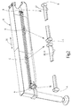
- the device shown in the drawing essentially comprises a support member 10, the like in a box 12 of a chassis 14 of a work machine such as a truck-mounted concrete pump or the like. slidably disposed, a latch mechanism 16 which is disposed on the outside of the box 12 and which has a housing 18 and a displaceable in this transverse to the withdrawal direction of the support member locking bolt 20, wherein the housing partially passes through an opening 22 in the wall of the box 12 , and three arranged on the support member latching and guide members 24, 26, 28 which extend between two engageable by the support member 10 end positions.
- the locking mechanism 16 is pivotally mounted about an axis 30 to the box 12 and the opening 22 is formed as a part-circular slot accordingly.
- the locking mechanism 16 has a handle 32 with which the locking mechanism can be brought into one of three pivotal positions, which each assign the locking mechanism to one of the three locking and guiding members 24, 26, 28.
- the three locking and guide members 24, 26, 28 are formed substantially rail-like and provide a total of four locking positions for the locking bolt 20: each a detent position in the fully retracted transport position of the support member 10 (first detent position A) and the fully extended support position of the support member 10th (Second locking position B), and two arranged between these extreme positions further locking positions C and D, if a complete extension of the support member is not possible or necessary.
- the three locking and guide members 24, 26, 28 further have guide curves for the automatic release of the locking bolt 20, as will be explained in more detail below.
- the latching and guide member 26 extends without interruption between the latching positions A and B.
- the latching and guide member 24 has at a first distance from the latching position A the latching position C forming interruption
- the latching and guide member 28 has at a second distance from the latching position A a the latching position D forming interruption and beyond also also extends to the latching position B.
- the locking mechanism 16 is pivoted to a position associated with one of the three locking and guiding members.
- the structure and operation of the locking mechanism 16 is in the EP 0 633 847 B1 described in detail.
- the locking bolt 20 accordingly has three functional positions: a blocking position, an unlocking position and a release position.
- the locking bolt 20 In the blocking position, the locking bolt 20 is pushed out of this by the action of a spring arranged in the housing 18 of the locking mechanism. How out Fig. 3 the locking bolt 20 then forms a stop for the front end face of one of the three locking and guide elements (in both end positions A and B of the support member 10) and the frontal boundary surfaces of the interruptions of the locking and guide members 24 and 28 (in the two intermediate positions C and D of the support member 10). The support member 10 is then blocked in its direction of displacement, ie locked with respect to the chassis of the driving machine.
- the locking bolt 20 is moved by manual operation of a lever 34 of the locking mechanism 16 by an operator against the spring force in its unlocked position in which the locking bolt 20 is pushed into the housing 18 and secured in this position, ie without external action remains the locking bolt 20th despite the action of the spring force in this position.
- the respective locking and guide member is released in this position of the locking bolt 20 and the support member 10 can in both displacement directions (double arrow 36 in Fig. 2 ) are moved.
- the latching and guide elements 24, 26, 28 in the direction of the latch mechanism 16 projecting guide curves 38, 40, 42, which move the locking bolt 20 from its unlocked position into its release position.
- the locking bolt 20 is displaced by the arranged in the housing 18 of the locking mechanism 16 spring into its blocking position. This takes place as soon as the obstacle formed by the guide curve 38, 40, 42 has been overcome. The locking bolt 20 then automatically snaps into the following locking position in the direction of displacement.
- latching and guide elements 24 and 28 extend beyond the respective latching positions C and D further to the latching position B, but this opens up the possibility of the support member 10 of these latching positions C, D fully extend to latching position B, without the support member 10 previously fully retract to the latching position A to then by selecting the locking and guide element 26 to allow extension of the support member 10 into the latching position B.
- this embodiment of the locking and guiding elements allows the selective approach of the locking positions A, C and D of the locking position B.
- the locking mechanism 16 is first unlocked manually by the operator by means of the lever 34.
- the locking bolt is in turn moved by the respective guide curve 38, 40 or 42 in its release position and slides after passing the guide curve on the rail-like surface of the locking and guide element until it automatically engages in reaching the locking position A in this.
- the invention relates to a locking device for arranged on a driving or support frame and extendable from a retracted transport position in an extended working position, swing out or telescoping support members 10 for a work machine, with a locking bolt 20 in a fixed to the frame, transverse to Ausziehraum the support member 10 arranged housing 18 is displaceable between a blocking position and an unlocking and is biased under the action of a spring in the blocking position, with a locking bolt 20 between the locking position and the unlocked position sliding actuator 34, and rigidly arranged on the support member 10 Resting and guide member 24, 26, 28 for the locking bolt, wherein the locking and guide member has a locking bolt 20 in a release position sliding guide rail 38, 40, 42 and wherein the locking bolt 20 in the release position selb sttätig is movable into its blocking position.
- At least two locking and guide members 24, 26, 28 are provided, of which one without interruption between a first latching position A for the locking bolt 20 in the retracted transport position of the support member 10 and a second detent position B for the locking bolt 20 in the fully extended, swung-out or telescoped working position of the support member 10 extends and the second arranged between the first and second detent position detent position C, D. having.
Landscapes
- Engineering & Computer Science (AREA)
- Mechanical Engineering (AREA)
- Jib Cranes (AREA)
- Fittings On The Vehicle Exterior For Carrying Loads, And Devices For Holding Or Mounting Articles (AREA)
Description
- Die Erfindung betrifft eine Verriegelungsvorrichtung für an einem Fahr- oder Traggestell angeordnete und von einer eingezogenen Transportstellung in eine ausgezogene Arbeitsstellung ausfahrbare, ausschwenkbare oder teleskopierbare Stützorgane für eine Arbeitsmaschine, mit einem Riegelbolzen, der in einem gestellfesten, quer zur Ausziehrichtung des Stützorgans angeordneten Gehäuse zwischen einer Sperrstellung und einer Entsperrstellung verschiebbar ist und unter Einwirkung einer Feder in Richtung Sperrstellung vorgespannt ist, mit einem den Riegelbolzen zwischen der Sperrstellung und der Entsperrstellung verschiebenden Betätigungsorgan, und mit einem an dem Stützorgan starr angeordneten Rast- und Leitorgan für den Riegelbolzen, wobei das Rast- und Leitorgan eine den Riegelbolzen in eine Freigabestellung schiebende Leitkurve aufweist und wobei der Riegelbolzen in der Freigabestellung selbsttätig in seine Sperrstellung bewegbar ist.
- Fahrbare Arbeitsmaschinen mit Kran- oder Verteilermastaufbauten werden in der Arbeitsstellung üblicherweise mit seitlich ausfahrbaren oder ausschwenkbaren Stützbeinen am Boden abgestützt (
EP-A 0 357 988 ). Dabei ist es wichtig, dass die beispielsweise mittels Hydromotoren ausfahrbaren Stützorgane sowohl in ihrer inneren Transportstellung als auch in ihrer Abstützstellung mit Hilfe der Verriegelungsvorrichtung wirksam und zuverlässig arretiert sind. Eine Verriegelungsvorrichtung der eingangs genannten Art ist aus derDE 42 11 493 A1 bekannt. Diese Vorrichtung weist ein Rast- und Leitorgan auf, das je eine in der inneren Transportstellung als auch in der Abstützstellung eines Stützorgans gegen einen in einer Sperrstellung befindlichen Riegelbolzen anschlagende Riegelfläche sowie eine sich im Bereich zwischen den beiden Riegelflächen erstreckende, auf den Riegelbolzen einwirkende und diesen zwischen seiner Entsperrstellung und Freigabestellung verschiebende Leitkurve aufweist. - Vor dem Verlassen einer der zwei Endstellungen des Stützorgans wird die Verriegelungsvorrichtung manuell entriegelt. Dabei wird der Riegelbolzen der Verriegelungsvorrichtung in eine vorgespannte Entsperrstellung verschoben. Wird daraufhin eines der Rast- und Leitorgane überfahren, so wird der Riegelbolzen durch die Leitkurve des Rast- und Leitorgans in seine Freigabestellung gebracht und rastet hinter dem Rast- und Leitorgan selbsttätig in die Sperrstellung. Das Stützorgan ist dann bis zur nächsten manuellen Entriegelung der Verriegelungsvorrichtung in seiner Position gesichert. Gelegentlich ist die Arbeitsumgebung jedoch dergestalt, dass ein vollständiges Ausfahren eines oder mehrerer der Stützorgane nicht möglich ist, beispielsweise wenn die Arbeitsmaschine in der Nähe einer Wand oder eines anderen Hindernisses positioniert ist. Gleichwohl ist es auch in solchen Fällen wichtig, dass die Stützorgane in eine wohldefinierte Abstützposition gebracht werden, da der zulässige Schwenkbereich eines Krans oder Verteilermastes durch die Stützweite begrenzt ist. Dabei ist zu berücksichtigen, dass die Stützorgane oft durch einen Kettenantrieb aus- und eingefahren werden, da dies leichter und kostengünstiger als die Verwendung von Hydrozylindern zu diesem Zweck ist. Ein Kettenantrieb weist jedoch den Nachteil auf, dass er Lasten in Teleskop- oder Ausschubrichtung nicht aufnehmen kann, so dass die zusätzliche Sicherung durch eine vorstehend beschriebene mechanische Sperre erforderlich ist. Um eine mechanische Sperre in den Zwischenstellungen zu verwirklichen, wäre es grundsätzlich möglich, das Rast- und Leitorgan mit Rastpositionen an den gewünschten Stellen zu versehen. Allerdings rastet der Riegelbolzen auf Grund der Automatikfunktion der Verriegelungsvorrichtung dann in jeder Zwischenstellung ein, so dass zum Überfahren der Zwischenstellung jeweils eine manuelle Entriegelung durch die Bedienperson vorgenommen werden müsste. Dies wird als zu umständlich erachtet.
- Ausgehend hiervon besteht die Aufgabe der vorliegenden Erfindung darin, eine Vorrichtung der eingangs genannten Art so weiter zu entwickeln, dass eine wahlweise, automatische Sperrung des Verschiebewegs des Stützorgans sowohl in den Endstellungen als auch dazwischen möglich ist.
- Zur Lösung dieser Aufgabe wird die in Patentanspruch 1 angegebene Merkmalskombination vorgeschlagen. Vorteilhafte Weiterbildungen und Ausgestaltungen der Erfindung ergeben sich aus den abhängigen Ansprüchen.
- Der Erfindung liegt vor allem der Gedanke zu Grunde, dass eine Arretierung des Stützorgans im teilweise ausgefahrenen Zustand gelegentlich, jedoch nicht immer wünschenswert ist. Es soll dabei eine ausdrückliche Vorwahl der Bedienperson stattfinden. Erfindungsgemäß wird dies dadurch erreicht, dass mindestens zwei Rast- und Leitorgane vorgesehen sind, von denen sich eines ohne Unterbrechung zwischen einer ersten Rastposition für den Riegelbolzen im Bereich der eingezogenen Transportstellung des Stützorgans und einer zweiten Rastposition für den Riegelbolzen im Bereich der vollständig ausgefahrenen, ausgeschwenkten oder teleskopierten Arbeitsstellung des Stützorgans erstreckt und das zweite eine zwischen der ersten und zweiten Rastposition angeordnete Rastposition aufweist. Dabei ist das Gehäuse des Riegelbolzens derart schwenkbar oder verschiebbar an dem Gestell angeordnet, dass der Riegelbolzen einem der vorhanden Rast- und Leitorgane zugeordnet werden kann. Die Bedienperson muss damit lediglich die gewünschte Rastposition durch Auswahl eines der Rast- und Leitorgane vorgeben und den Riegelbolzen manuell entsperren. Das Stützorgan kann dann ohne weiteres Eingreifen der Bedienperson in die gewünschte Auszugsstellung gefahren werden, wo der Riegelbolzen automatisch einrastet und das Stützorgan arretiert.
- Grundsätzlich ist es hierbei ausreichend wenn sich das zweite und gegebenenfalls weitere Rast- und Leitorgane lediglich bis zu ihrer jeweiligen Rastposition erstrecken. In bevorzugter Ausgestaltung der Erfindung ist jedoch vorgesehen, dass sich auch das zweite und weitere Rast- und Leitorgane zwischen der ersten und der zweiten Rastposition erstrecken, also über die jeweilige Zwischenrastposition hinaus bis zur äußersten Rastposition, in der das Stützorgan vollständig ausgefahren ist.
- Zur automatischen Auslösung des Riegelbolzens ist eine an den Rast- und Leitorganen vorgesehene Leitkurve dienlich. Das die unmittelbare Anwahl der vollständig ausgefahrenen Stellung des Stützorgans ermöglichende Rast- und Leitorgan weist eine, zwischen der ersten und zweiten Rastposition angeordnete Leitkurve auf. Das zweite und weitere Rast- und Leitorgane weisen sowohl zwischen der ersten Rastposition und der Zwischenrastposition als auch zwischen der Zwischenrastposition und der zweiten Rastposition eine Leitkurve für den Riegelbolzen auf. Somit ist es möglich, das Stützorgan aus jeder momentanen Rastposition in eine andere Rastposition entlang des jeweiligen Rast- und Leitelements zu verfahren unter Beibehaltung der automatischen Auslösung des Riegelbolzens in der Rastposition nach manuellem Entsperren des Riegelbolzens durch die Bedienperson. Die Rast- und Leitorgane umfassen zweckmäßig jeweils ein Schienenelement mit einer Gleitfläche für den sich in der Freigabestellung befindlichen Riegelbolzen. Nach der Auslösung des Riegelbolzens durch eine der Leitkurven gleitet der Riegelbolzen dann so lange auf dem Schienenelement, bis die folgende Rastposition erreicht ist. Die zwischen der ersten und zweiten Rastposition angeordnete Rastposition für den Riegelbolzen ist zweckmäßig durch eine Unterbrechung in dem Schienenelement gebildet.
- Die Möglichkeit der Arretierung des Stützorgans in einer teilweise ausgefahrenen Position wird aus Sicherheitsgründen durch eine sensorische Überwachung der Ist-Position des Stützorgans ergänzt, die Teil einer elektronischen Steuerungsvorrichtung für den Kran oder Verteilermast ist. Eine derartige Steuerungsvorrichtung ist beispielsweise aus der
EP 2 038 493 B1 bekannt. Dort ist eine Autobetonpumpe beschrieben, mit einem als Träger für eine Förderleitung dienenden Knickmast und mit zwei vorderen und zwei rückwärtigen, von einer Fahrstellung in eine Abstützstellung ausfahrbaren, mit je einem teleskopierbaren Stützbein auf einem Untergrund abstützbaren Stützauslegern. Außerdem weist jeder Stützausleger eine innere, fahrgestellnahe und mindestens eine äußere, fahrgestellferne Abstützstellung auf, die unter Bildung definierter Abstützkonfigurationen für die vier Stützausleger frei wählbar sind. Weiter ist eine Steuerungseinrichtung für die Mastarmbewegung vorgesehen, die eine auf die gewählte Abstützkonfiguration ansprechende Softwareroutine aufweist, die den Schwenkwinkel des ersten Knickarms um seine Knickachse und einen zugehörigen Drehwinkelbereich des Drehkopfs um die Hochachse nach Maßgabe der gewählten Abstützkonfiguration begrenzt. Eine Besonderheit der dort beschriebenen Erfindung besteht darin, dass ein Wählschalter mit mehreren, verschiedenen Abstützkonfigurationen entsprechenden Schaltstellungen vorgesehen ist, und dass die Steuerungseinrichtung für die Mastarmbewegung auf die Schaltstellungen des Wählschalters anspricht. Die Steuerungseinrichtung für die Mastarmbewegung weist außerdem eine auf die gewählte Abstützkonfiguration ansprechende Softwareroutine oder Begrenzungsschaltung auf, die den Schwenkwinkelbereich des ersten Mastarms um seine Knickachse und einen zugehörigen Drehwinkelbereich des Drehkopfs um seine Hochachse nach Maßgabe der gewählten Abstützkonfiguration begrenzt. Die sensorisch erfassten Zwischenrastpositionen der vorliegenden Erfindung werden vorteilhaft in eine derartige Steuerungseinrichtung eingebunden. - Im Folgenden wird die Erfindung anhand eines in der Zeichnung in schematischer Weise dargestellten Ausführungsbeispiels näher erläutert. Es zeigen
- Fig. 1
- eine perspektivische Ansicht eines Gestells einer Arbeitsmaschine im Bereich einer kastenartigen Aufnahme für ein Stützorgan, mit einem an dem Gestell schwenkbar angeordneten Riegelmechanismus zum Arretieren des Stützorgans;
- Fig. 2
- eine perspektivische Ansicht des Stützorgans mit drei Rast- und Leitorganen für den Riegelmechanismus gemäß
Fig. 1 ; und - Fig. 3
- eine Stirnseitenansicht des Gestells mit dem daran angeordneten Riegelmechanismus, und des Stützorgans.
- Die in der Zeichnung dargestellte Vorrichtung umfasst im Wesentlichen ein Stützorgan 10, das in einem Kasten 12 eines Fahrgestells 14 einer Arbeitsmaschine wie einer Autobetonpumpe o.dgl. verschiebbar angeordnet ist, einen Riegelmechanismus 16, der außenseitig an dem Kasten 12 angeordnet ist und der ein Gehäuse 18 und ein in diesem quer zu Ausziehrichtung des Stützorgans verschiebbaren Riegelbolzen 20 aufweist, wobei das Gehäuse teilweise durch eine Öffnung 22 in der Wandung des Kastens 12 hindurchtritt, und drei an dem Stützorgan angeordnete Rast- und Leitorgane 24, 26, 28, die sich zwischen zwei von dem Stützorgan 10 einnehmbaren Endpositionen erstrecken.
- Der Riegelmechanismus 16 ist um eine Achse 30 schwenkbar an dem Kasten 12 befestigt und die Öffnung 22 entsprechend als teilkreisförmiges Langloch ausgebildet. Der Riegelmechanismus 16 weist einen Handgriff 32 auf, mit dem der Riegelmechanismus in eine von drei Schwenkpositionen gebracht werden kann, die den Riegelmechanismus jeweils einem der drei Rast- und Leitorgane 24, 26, 28 zuordnen.
- Die drei Rast- und Leitorgane 24, 26, 28 sind im Wesentlichen schienenartig ausgebildet und bieten insgesamt vier Rastpositionen für den Riegelbolzen 20: Jeweils eine Rastposition in der vollständig eingefahrenen Transportstellung des Stützorgans 10 (erste Rastposition A) und der vollständig ausgefahrenen Abstützstellung des Stützorgans 10 (zweite Rastposition B), sowie zwei zwischen diesen Extremstellungen angeordnete weitere Rastpositionen C und D, falls ein vollständiges Ausfahren des Stützorgans nicht möglich oder erforderlich ist. Die drei Rast- und Leitorgane 24, 26, 28 weisen weiterhin Leitkurven zur automatischen Auslösung des Riegelbolzens 20 auf, wie unten näher ausgeführt werden wird.
- Das Rast- und Leitorgan 26 erstreckt sich ohne Unterbrechung zwischen den Rastpositionen A und B. Das Rast- und Leitorgan 24 weist in einem ersten Abstand von der Rastposition A eine die Rastposition C bildende Unterbrechung auf und erstreckt sich darüber hinaus bis zur Rastposition B. Das Rast- und Leitorgan 28 weist in einem zweiten Abstand von der Rastposition A eine die Rastposition D bildende Unterbrechung auf und erstreckt sich darüber hinaus ebenfalls bis zur Rastposition B. Zur Auswahl der gewünschten Rastposition B, C oder D (ausgehend von der Rastposition A) wird der Riegelmechanismus 16 in eine Stellung geschwenkt, die einem der drei Rast- und Leitorgane zugeordnet ist.
- Der Aufbau und die Funktionsweise des Riegelmechanismus 16 ist in der
EP 0 633 847 B1 ausführlich beschrieben. Der Riegelbolzen 20 weist demnach drei Funktionsstellungen auf: Eine Sperrstellung, eine Entsperrstellung und eine Freigabestellung. - In der Sperrstellung ist der Riegelbolzen 20 durch Krafteinwirkung einer in dem Gehäuse 18 des Riegelmechanismus angeordneten Feder aus diesem heraus geschoben. Wie aus
Fig. 3 ersichtlich bildet der Riegelbolzen 20 dann einen Anschlag für die stirnseitige Endfläche eines der drei Rast- und Leitorgane (in beiden Endpositionen A und B des Stützorgans 10) bzw. die stirnseitigen Begrenzungsflächen der Unterbrechungen der Rast- und Leitorgane 24 und 28 (in den zwei Zwischenpositionen C und D des Stützorgans 10). Das Stützorgan 10 ist dann in seiner Verschieberichtung blockiert, d. h. bezüglich dem Fahrgestell der Fahrmaschine arretiert. - Der Riegelbolzen 20 wird durch manuelle Betätigung eines Hebels 34 des Riegelmechanismus 16 von einer Bedienperson entgegen der Federkraft in seine Entsperrstellung verschoben, in der der Riegelbolzen 20 in das Gehäuse 18 hinein geschoben und in dieser Stellung gesichert ist, d. h. ohne äußere Einwirkung verbleibt der Riegelbolzen 20 trotz Einwirkens der Federkraft in dieser Stellung. Das jeweilige Rast- und Leitorgan ist in dieser Stellung des Riegelbolzens 20 freigegeben und das Stützorgan 10 kann in beiden Verschieberichtungen (Doppelpfeil 36 in
Fig. 2 ) bewegt werden. Zwischen der Rastposition A und den Rastpositionen B, C und D, sowie zwischen den Rastpositionen C, D und der Rastposition B, weisen die Rast- und Leitorgane 24, 26, 28 in Richtung des Riegelmechanismus 16 überstehende Leitkurven 38, 40, 42 auf, die den Riegelbolzen 20 aus seiner Entsperrstellung in seine Freigabestellung verschieben. Aus dieser Freigabestellung heraus wird der Riegelbolzen 20 durch die in dem Gehäuse 18 des Riegelmechanismus 16 angeordnete Feder in seine Sperrstellung verschoben. Dies erfolgt, sobald das durch die Leitkurve 38, 40, 42 gebildete Hindernis überwunden ist. Der Riegelbolzen 20 schnappt dann automatisch in die in Verschieberichtung folgende Rastposition ein. - Grundsätzlich ist es zur Realisierung der Erfindung zwar nicht erforderlich, dass sich die Rast- und Leitorgane 24 und 28 über die jeweiligen Rastpositionen C und D hinaus weiter bis zur Rastposition B erstrecken, jedoch eröffnet dies die Möglichkeit, das Stützorgan 10 von diesen Rastpositionen C, D aus vollständig bis zur Rastposition B auszufahren, ohne das Stützorgan 10 zuvor vollständig bis zur Rastposition A einzufahren um dann durch Anwahl des Rast- und Leitelements 26 ein Ausfahren des Stützelements 10 bis in die Rastposition B zu ermöglichen. Ebenso ermöglicht diese Ausgestaltung der Rast- und Leitelemente das wahlweise Anfahren der Rastpositionen A, C und D von der Rastposition B aus.
- Soll das Stützorgan 10 von den Rastpositionen C, D oder B aus zurück in die Rastposition A gefahren werden, so wird der Riegelmechanismus 16 von der Bedienperson zunächst mittels des Hebels 34 manuell entsperrt. Der Riegelbolzen wird wiederum von der jeweiligen Leitkurve 38, 40 oder 42 in seine Freigabestellung verschoben und gleitet nach dem Passieren der Leitkurve auf der schienenartigen Oberfläche der Rast- und Leitorgans, bis er bei erreichen der Rastposition A automatisch in diese einrastet.
- In der vorstehend beschriebenen Zeichnung sind lediglich die mechanischen Komponenten der Vorrichtung dargestellt und beschreiben. Es sind jedoch darüber hinaus elektronische Komponenten wie Positionssensoren für das Stützorgan 10 und die Verriegelungsvorrichtung vorgesehen, die in ein Steuerungssystem der Arbeitsmaschine eingebunden sind und sicherstellen, dass ein zulässiger Schwenkbereich eines Krans oder Verteilermastes auch bei nur teilweise ausgefahrenen Stützorganen nicht überschritten wird.
- Zusammenfassend ist folgendes festzuhalten: Die Erfindung betrifft eine Verriegelungsvorrichtung für an einem Fahr- oder Traggestell angeordnete und von einer eingezogenen Transportstellung in eine ausgezogene Arbeitsstellung ausfahrbare, ausschwenkbare oder teleskopierbare Stützorgane 10 für eine Arbeitsmaschine, mit einem Riegelbolzen 20, der in einem gestellfesten, quer zur Ausziehrichtung des Stützorgans 10 angeordneten Gehäuse 18 zwischen einer Sperrstellung und einer Entsperrstellung verschiebbar ist und unter Einwirkung einer Feder in Richtung Sperrstellung vorgespannt ist, mit einem den Riegelbolzen 20 zwischen der Sperrstellung und der Entsperrstellung verschiebenden Betätigungsorgan 34, und mit einem an dem Stützorgan 10 starr angeordneten Rast- und Leitorgan 24, 26, 28 für den Riegelbolzen, wobei das Rast- und Leitorgan eine den Riegelbolzen 20 in eine Freigabestellung schiebende Leitkurve 38, 40, 42 aufweist und wobei der Riegelbolzen 20 in der Freigabestellung selbsttätig in seine Sperrstellung bewegbar ist. Um bei begrenzten Raumverhältnissen eine automatische Sperrung in unterschiedlichen, teilweise ausgefahrenen Positionen der Stützorgane zu ermöglichen, wird gemäß der Erfindung vorgeschlagen, dass mindestens zwei Rast- und Leitorgane 24, 26, 28 vorgesehen sind, von denen sich eines ohne Unterbrechung zwischen einer ersten Rastposition A für den Riegelbolzen 20 im Bereich der eingezogenen Transportstellung des Stützorgans 10 und einer zweiten Rastposition B für den Riegelbolzen 20 im Bereich der vollständig ausgefahrenen, ausgeschwenkten oder teleskopierten Arbeitsstellung des Stützorgans 10 erstreckt und das zweite eine zwischen der ersten und zweiten Rastposition angeordnete Rastposition C, D aufweist.
Claims (8)
- Verriegelungsvorrichtung für an einem Fahr- oder Traggestell angeordnete und von einer eingezogenen Transportstellung in eine ausgezogene Arbeitsstellung ausfahrbare, ausschwenkbare oder teleskopierbare Stützorgane (10) für eine Arbeitsmaschine, mit einem Riegelbolzen (20), der in einem gestellfesten, quer zur Ausziehrichtung des Stützorgans (10) angeordneten Gehäuse (18) zwischen einer Sperrstellung und einer Entsperrstellung verschiebbar ist und unter Einwirkung einer Feder in Richtung Sperrstellung vorgespannt ist, mit einem den Riegelbolzen (20) zwischen der Sperrstellung und der Entsperrstellung verschiebenden Betätigungsorgan (34), und mit einem an dem Stützorgan (10) starr angeordneten Rast- und Leitorgan (24, 26, 28) für den Riegelbolzen, wobei das Rast- und Leitorgan (24, 26, 28) eine den Riegelbolzen (20) in eine Freigabestellung schiebende Leitkurve (38, 40, 42) aufweist, und wobei der Riegelbolzen (20) in der Freigabestellung selbsttätig in seine Sperrstellung bewegbar ist, dadurch gekennzeichnet, dass mindestens zwei Rast- und Leitorgane (24, 26, 28) vorgesehen sind, von denen sich eines ohne Unterbrechung zwischen einer ersten Rastposition (A) für den Riegelbolzen (20) im Bereich der eingezogenen Transportstellung des Stützorgans (10) und einer zweiten Rastposition (B) für den Riegelbolzen (20) im Bereich der vollständig ausgefahrenen, ausgeschwenkten oder teleskopierten Arbeitsstellung des Stützorgans (10) erstreckt und das zweite eine zwischen der ersten und zweiten Rastposition angeordnete Rastposition (C, D) aufweist.
- Vorrichtung nach Anspruch 1, dadurch gekennzeichnet, dass sich auch das zweite Rast- und Leitorgan (24, 28) zwischen der ersten und der zweiten Rastposition (A, B) erstreckt.
- Vorrichtung nach Anspruch 1 oder 2, dadurch gekennzeichnet, dass die zwischen der ersten und zweiten Rastposition (A, B) angeordnete Rastposition (C, D) des zweiten und eines dritten Rast- und Leitorgans (24, 28) einen unterschiedlichen Abstand zu der ersten Rastposition (A) aufweisen.
- Vorrichtung nach einem der Ansprüche 1 bis 3, dadurch gekennzeichnet, dass die mindestens zwei Rast- und Leitorgane (24, 26, 28) parallel zueinander angeordnet sind.
- Vorrichtung nach einem der Ansprüche 1 bis 4, dadurch gekennzeichnet, dass das zweite Rast- und Leitorgan (24, 28) ein zwischen der ersten Rastposition (A) und der zwischen der ersten und zweiten Rastposition (B) angeordneten Rastposition (C, D) eine Leitkurve (38, 40, 42) aufweist, die den Riegelbolzen (20) von der Entsperrstellung in die Freigabestellung bewegt.
- Vorrichtung nach einem der Ansprüche 1 bis 5, dadurch gekennzeichnet, dass der Riegelbolzen (20) durch verschieben oder verschwenken des Gehäuses (18) an dem Gestell (12) wahlweise dem einen oder anderen Rast- und Leitorgan (24, 26, 28) zuordbar ist.
- Vorrichtung nach einem der Ansprüche 1 bis 6, dadurch gekennzeichnet, dass die Rast- und Leitorgane (24, 26, 28) jeweils ein Schienenelement mit einer Gleitfläche für den sich in der Freigabestellung befindlichen Riegelbolzen (20) aufweisen.
- Vorrichtung nach Anspruch 7, dadurch gekennzeichnet, dass die zwischen der ersten und zweiten Rastposition (A, B) angeordnete Rastposition (C, D) für den Riegelbolzen (20) durch eine Unterbrechung in dem Schienenelement gebildet ist.
Applications Claiming Priority (2)
| Application Number | Priority Date | Filing Date | Title |
|---|---|---|---|
| DE102012215546.5A DE102012215546A1 (de) | 2012-08-31 | 2012-08-31 | Verriegelungsvorrichtung |
| PCT/EP2013/067371 WO2014033025A1 (de) | 2012-08-31 | 2013-08-21 | Verriegelungsvorrichtung |
Publications (2)
| Publication Number | Publication Date |
|---|---|
| EP2890627A1 EP2890627A1 (de) | 2015-07-08 |
| EP2890627B1 true EP2890627B1 (de) | 2016-07-27 |
Family
ID=49035582
Family Applications (1)
| Application Number | Title | Priority Date | Filing Date |
|---|---|---|---|
| EP13753168.7A Active EP2890627B1 (de) | 2012-08-31 | 2013-08-21 | Verriegelungsvorrichtung |
Country Status (5)
| Country | Link |
|---|---|
| EP (1) | EP2890627B1 (de) |
| KR (1) | KR102000327B1 (de) |
| CN (1) | CN104364185B (de) |
| DE (1) | DE102012215546A1 (de) |
| WO (1) | WO2014033025A1 (de) |
Cited By (1)
| Publication number | Priority date | Publication date | Assignee | Title |
|---|---|---|---|---|
| WO2025162774A1 (de) * | 2024-01-30 | 2025-08-07 | Schwing Gmbh | Autobetonpumpe |
Families Citing this family (2)
| Publication number | Priority date | Publication date | Assignee | Title |
|---|---|---|---|---|
| CN107757741A (zh) * | 2017-10-11 | 2018-03-06 | 湖南千智机器人科技发展有限公司 | 一种带悬臂旋转机构的履带式机器人底盘侧向倾覆修正装置 |
| CN108214943B (zh) * | 2018-01-02 | 2019-08-27 | 绍兴市寅源智能科技有限公司 | 一种瓷砖切割用辅助定位装置 |
Family Cites Families (17)
| Publication number | Priority date | Publication date | Assignee | Title |
|---|---|---|---|---|
| SE394401C (sv) * | 1975-10-10 | 1978-12-18 | Berger Gunvald M S | Med atminstone tva stodben forsedd lastberare |
| JPS56119755U (de) * | 1980-02-16 | 1981-09-11 | ||
| US4397396A (en) * | 1980-11-07 | 1983-08-09 | Harnischfeger Corporation | Truck crane having an elongated main frame |
| US4394913A (en) * | 1980-11-07 | 1983-07-26 | Harnischfeger Corporation | Crane having power operated outriggers and lock means therefor |
| JPS58136547A (ja) * | 1982-02-09 | 1983-08-13 | Hitachi Constr Mach Co Ltd | 移動式クレ−ン等におけるアウトリガ装置 |
| JPS60130287U (ja) * | 1984-02-10 | 1985-08-31 | 株式会社タダノ | アウトリガ装置における可動部の固定装置の自動解除装置 |
| DE3830315A1 (de) | 1988-09-07 | 1990-03-08 | Putzmeister Maschf | Fahrbare betonpumpe |
| SE466593B (sv) * | 1990-05-04 | 1992-03-09 | Arne Henriksson Utveckling Kom | Anordning vid vaexelflak |
| DE4117631A1 (de) * | 1991-05-29 | 1992-12-03 | Europ Semi Remorques | Stuetzbein |
| JP2571062Y2 (ja) * | 1992-02-07 | 1998-05-13 | 株式会社加藤製作所 | アウトリガの自動ロツク装置 |
| DE4211493A1 (de) | 1992-04-06 | 1993-10-07 | Putzmeister Maschf | Verriegelungsvorrichtung für ausziehbare Stützorgane |
| JP4166500B2 (ja) * | 2002-04-26 | 2008-10-15 | 古河機械金属株式会社 | 手動式アウトリガ装置 |
| ATE295330T1 (de) * | 2003-02-14 | 2005-05-15 | Palfinger Ag | Transportsicherung |
| DE202005015516U1 (de) * | 2005-10-04 | 2007-02-08 | Liebherr-Werk Ehingen Gmbh | Abstützeinrichtung für einen Mobilkran |
| DE102006031257A1 (de) | 2006-07-06 | 2008-01-10 | Putzmeister Ag | Autobetonpumpe mit Knickmast |
| CN102287424B (zh) * | 2010-06-21 | 2013-04-17 | 北汽福田汽车股份有限公司 | 一种锁止机构 |
| CN102381291B (zh) * | 2011-09-14 | 2014-09-10 | 三一汽车制造有限公司 | 一种伸缩支腿及具有该伸缩支腿的工程机械 |
-
2012
- 2012-08-31 DE DE102012215546.5A patent/DE102012215546A1/de not_active Withdrawn
-
2013
- 2013-08-21 EP EP13753168.7A patent/EP2890627B1/de active Active
- 2013-08-21 CN CN201380029224.9A patent/CN104364185B/zh active Active
- 2013-08-21 WO PCT/EP2013/067371 patent/WO2014033025A1/de not_active Ceased
- 2013-08-21 KR KR1020157000082A patent/KR102000327B1/ko active Active
Cited By (1)
| Publication number | Priority date | Publication date | Assignee | Title |
|---|---|---|---|---|
| WO2025162774A1 (de) * | 2024-01-30 | 2025-08-07 | Schwing Gmbh | Autobetonpumpe |
Also Published As
| Publication number | Publication date |
|---|---|
| CN104364185B (zh) | 2016-09-28 |
| WO2014033025A1 (de) | 2014-03-06 |
| DE102012215546A1 (de) | 2014-03-06 |
| EP2890627A1 (de) | 2015-07-08 |
| CN104364185A (zh) | 2015-02-18 |
| KR102000327B1 (ko) | 2019-07-15 |
| KR20150051985A (ko) | 2015-05-13 |
Similar Documents
| Publication | Publication Date | Title |
|---|---|---|
| EP0433726B1 (de) | Einschiebe-Falttür-System für einen Schrank | |
| EP3549900B1 (de) | Hebebühne für kraftfahrzeuge | |
| WO1994017265A1 (de) | Klettervorrichtung, insbesondere für ein klettergerüst | |
| EP2890628B1 (de) | Verriegelungsvorrichtung | |
| WO2017081021A1 (de) | Mobilkran und verfahren zum abwinkeln einer hauptauslegerverlängerung relativ zu einem hauptausleger eines mobilkrans | |
| EP2402512B1 (de) | Frontlader für einen traktor | |
| DE10048224B4 (de) | Verriegelungseinheit für einen Teleskopausleger eines Krans | |
| EP4351925A1 (de) | Absenkbare containerverriegelung | |
| DE102011116083B4 (de) | Sicherungs- und Verriegelungseinheit für Ausleger mit teleskopierbaren Schüssen, insbesondere bei Mobilkranen | |
| EP2890627A1 (de) | Verriegelungsvorrichtung | |
| EP3159452B1 (de) | Frontlader | |
| EP1323871B1 (de) | "Abstützvorrichtung für Baumaschinen wie Hydraulikbagger und dergleichen" | |
| DE102012002122A1 (de) | Verriegelungsvorrichtung für einen Teleskopausleger | |
| EP0633847B1 (de) | Verriegelungsvorrichtung für ausziehbare stützorgane | |
| EP1293611B1 (de) | Frontlader | |
| EP3089890B1 (de) | Abdeckvorrichtung eines kofferraumfachs eines kraftfahrzeugs | |
| DE19947188C2 (de) | Ausziehtisch mit einem Tischgestell | |
| DE202004017598U1 (de) | Teleskopausleger | |
| DE202020105843U1 (de) | Semiautomatische Bolzenverbindung | |
| DE202020100268U1 (de) | Verteilermast für eine Betonpumpe und mobile Betonpumpe mit einem solchen Verteilermast | |
| DE2201683C2 (de) | Kraneinrichtung | |
| WO2002076874A1 (de) | Teleskopausleger für einen fahrzeugkran | |
| DE102010015477B4 (de) | Gerüstaufzug | |
| DE10154548C2 (de) | Schnellwechselvorrichtung | |
| EP1810736B1 (de) | Teleskopanordnung und Spielzeugfahrzeug mit einer derartigen Teleskopanordnung |
Legal Events
| Date | Code | Title | Description |
|---|---|---|---|
| PUAI | Public reference made under article 153(3) epc to a published international application that has entered the european phase |
Free format text: ORIGINAL CODE: 0009012 |
|
| 17P | Request for examination filed |
Effective date: 20140925 |
|
| AK | Designated contracting states |
Kind code of ref document: A1 Designated state(s): AL AT BE BG CH CY CZ DE DK EE ES FI FR GB GR HR HU IE IS IT LI LT LU LV MC MK MT NL NO PL PT RO RS SE SI SK SM TR |
|
| AX | Request for extension of the european patent |
Extension state: BA ME |
|
| DAX | Request for extension of the european patent (deleted) | ||
| GRAP | Despatch of communication of intention to grant a patent |
Free format text: ORIGINAL CODE: EPIDOSNIGR1 |
|
| INTG | Intention to grant announced |
Effective date: 20160331 |
|
| GRAS | Grant fee paid |
Free format text: ORIGINAL CODE: EPIDOSNIGR3 |
|
| GRAP | Despatch of communication of intention to grant a patent |
Free format text: ORIGINAL CODE: EPIDOSNIGR1 |
|
| GRAA | (expected) grant |
Free format text: ORIGINAL CODE: 0009210 |
|
| INTG | Intention to grant announced |
Effective date: 20160613 |
|
| AK | Designated contracting states |
Kind code of ref document: B1 Designated state(s): AL AT BE BG CH CY CZ DE DK EE ES FI FR GB GR HR HU IE IS IT LI LT LU LV MC MK MT NL NO PL PT RO RS SE SI SK SM TR |
|
| REG | Reference to a national code |
Ref country code: GB Ref legal event code: FG4D Free format text: NOT ENGLISH |
|
| REG | Reference to a national code |
Ref country code: CH Ref legal event code: EP |
|
| REG | Reference to a national code |
Ref country code: AT Ref legal event code: REF Ref document number: 815639 Country of ref document: AT Kind code of ref document: T Effective date: 20160815 |
|
| REG | Reference to a national code |
Ref country code: IE Ref legal event code: FG4D Free format text: LANGUAGE OF EP DOCUMENT: GERMAN |
|
| REG | Reference to a national code |
Ref country code: DE Ref legal event code: R096 Ref document number: 502013003900 Country of ref document: DE |
|
| REG | Reference to a national code |
Ref country code: LT Ref legal event code: MG4D |
|
| REG | Reference to a national code |
Ref country code: NL Ref legal event code: MP Effective date: 20160727 |
|
| PG25 | Lapsed in a contracting state [announced via postgrant information from national office to epo] |
Ref country code: BE Free format text: LAPSE BECAUSE OF NON-PAYMENT OF DUE FEES Effective date: 20160831 |
|
| PG25 | Lapsed in a contracting state [announced via postgrant information from national office to epo] |
Ref country code: HR Free format text: LAPSE BECAUSE OF FAILURE TO SUBMIT A TRANSLATION OF THE DESCRIPTION OR TO PAY THE FEE WITHIN THE PRESCRIBED TIME-LIMIT Effective date: 20160727 Ref country code: LT Free format text: LAPSE BECAUSE OF FAILURE TO SUBMIT A TRANSLATION OF THE DESCRIPTION OR TO PAY THE FEE WITHIN THE PRESCRIBED TIME-LIMIT Effective date: 20160727 Ref country code: FI Free format text: LAPSE BECAUSE OF FAILURE TO SUBMIT A TRANSLATION OF THE DESCRIPTION OR TO PAY THE FEE WITHIN THE PRESCRIBED TIME-LIMIT Effective date: 20160727 Ref country code: RS Free format text: LAPSE BECAUSE OF FAILURE TO SUBMIT A TRANSLATION OF THE DESCRIPTION OR TO PAY THE FEE WITHIN THE PRESCRIBED TIME-LIMIT Effective date: 20160727 Ref country code: NL Free format text: LAPSE BECAUSE OF FAILURE TO SUBMIT A TRANSLATION OF THE DESCRIPTION OR TO PAY THE FEE WITHIN THE PRESCRIBED TIME-LIMIT Effective date: 20160727 Ref country code: IS Free format text: LAPSE BECAUSE OF FAILURE TO SUBMIT A TRANSLATION OF THE DESCRIPTION OR TO PAY THE FEE WITHIN THE PRESCRIBED TIME-LIMIT Effective date: 20161127 Ref country code: NO Free format text: LAPSE BECAUSE OF FAILURE TO SUBMIT A TRANSLATION OF THE DESCRIPTION OR TO PAY THE FEE WITHIN THE PRESCRIBED TIME-LIMIT Effective date: 20161027 |
|
| PG25 | Lapsed in a contracting state [announced via postgrant information from national office to epo] |
Ref country code: ES Free format text: LAPSE BECAUSE OF FAILURE TO SUBMIT A TRANSLATION OF THE DESCRIPTION OR TO PAY THE FEE WITHIN THE PRESCRIBED TIME-LIMIT Effective date: 20160727 Ref country code: LV Free format text: LAPSE BECAUSE OF FAILURE TO SUBMIT A TRANSLATION OF THE DESCRIPTION OR TO PAY THE FEE WITHIN THE PRESCRIBED TIME-LIMIT Effective date: 20160727 Ref country code: PL Free format text: LAPSE BECAUSE OF FAILURE TO SUBMIT A TRANSLATION OF THE DESCRIPTION OR TO PAY THE FEE WITHIN THE PRESCRIBED TIME-LIMIT Effective date: 20160727 Ref country code: PT Free format text: LAPSE BECAUSE OF FAILURE TO SUBMIT A TRANSLATION OF THE DESCRIPTION OR TO PAY THE FEE WITHIN THE PRESCRIBED TIME-LIMIT Effective date: 20161128 Ref country code: SE Free format text: LAPSE BECAUSE OF FAILURE TO SUBMIT A TRANSLATION OF THE DESCRIPTION OR TO PAY THE FEE WITHIN THE PRESCRIBED TIME-LIMIT Effective date: 20160727 Ref country code: GR Free format text: LAPSE BECAUSE OF FAILURE TO SUBMIT A TRANSLATION OF THE DESCRIPTION OR TO PAY THE FEE WITHIN THE PRESCRIBED TIME-LIMIT Effective date: 20161028 |
|
| REG | Reference to a national code |
Ref country code: CH Ref legal event code: PL |
|
| PG25 | Lapsed in a contracting state [announced via postgrant information from national office to epo] |
Ref country code: MC Free format text: LAPSE BECAUSE OF FAILURE TO SUBMIT A TRANSLATION OF THE DESCRIPTION OR TO PAY THE FEE WITHIN THE PRESCRIBED TIME-LIMIT Effective date: 20160727 Ref country code: EE Free format text: LAPSE BECAUSE OF FAILURE TO SUBMIT A TRANSLATION OF THE DESCRIPTION OR TO PAY THE FEE WITHIN THE PRESCRIBED TIME-LIMIT Effective date: 20160727 Ref country code: CH Free format text: LAPSE BECAUSE OF NON-PAYMENT OF DUE FEES Effective date: 20160831 Ref country code: LI Free format text: LAPSE BECAUSE OF NON-PAYMENT OF DUE FEES Effective date: 20160831 Ref country code: RO Free format text: LAPSE BECAUSE OF FAILURE TO SUBMIT A TRANSLATION OF THE DESCRIPTION OR TO PAY THE FEE WITHIN THE PRESCRIBED TIME-LIMIT Effective date: 20160727 |
|
| REG | Reference to a national code |
Ref country code: DE Ref legal event code: R097 Ref document number: 502013003900 Country of ref document: DE |
|
| PG25 | Lapsed in a contracting state [announced via postgrant information from national office to epo] |
Ref country code: CZ Free format text: LAPSE BECAUSE OF FAILURE TO SUBMIT A TRANSLATION OF THE DESCRIPTION OR TO PAY THE FEE WITHIN THE PRESCRIBED TIME-LIMIT Effective date: 20160727 Ref country code: SK Free format text: LAPSE BECAUSE OF FAILURE TO SUBMIT A TRANSLATION OF THE DESCRIPTION OR TO PAY THE FEE WITHIN THE PRESCRIBED TIME-LIMIT Effective date: 20160727 Ref country code: BG Free format text: LAPSE BECAUSE OF FAILURE TO SUBMIT A TRANSLATION OF THE DESCRIPTION OR TO PAY THE FEE WITHIN THE PRESCRIBED TIME-LIMIT Effective date: 20161027 Ref country code: DK Free format text: LAPSE BECAUSE OF FAILURE TO SUBMIT A TRANSLATION OF THE DESCRIPTION OR TO PAY THE FEE WITHIN THE PRESCRIBED TIME-LIMIT Effective date: 20160727 Ref country code: SM Free format text: LAPSE BECAUSE OF FAILURE TO SUBMIT A TRANSLATION OF THE DESCRIPTION OR TO PAY THE FEE WITHIN THE PRESCRIBED TIME-LIMIT Effective date: 20160727 |
|
| REG | Reference to a national code |
Ref country code: IE Ref legal event code: MM4A |
|
| PLBE | No opposition filed within time limit |
Free format text: ORIGINAL CODE: 0009261 |
|
| STAA | Information on the status of an ep patent application or granted ep patent |
Free format text: STATUS: NO OPPOSITION FILED WITHIN TIME LIMIT |
|
| 26N | No opposition filed |
Effective date: 20170502 |
|
| REG | Reference to a national code |
Ref country code: FR Ref legal event code: ST Effective date: 20170609 |
|
| PG25 | Lapsed in a contracting state [announced via postgrant information from national office to epo] |
Ref country code: FR Free format text: LAPSE BECAUSE OF NON-PAYMENT OF DUE FEES Effective date: 20160927 Ref country code: IE Free format text: LAPSE BECAUSE OF NON-PAYMENT OF DUE FEES Effective date: 20160821 |
|
| PG25 | Lapsed in a contracting state [announced via postgrant information from national office to epo] |
Ref country code: SI Free format text: LAPSE BECAUSE OF FAILURE TO SUBMIT A TRANSLATION OF THE DESCRIPTION OR TO PAY THE FEE WITHIN THE PRESCRIBED TIME-LIMIT Effective date: 20160727 Ref country code: LU Free format text: LAPSE BECAUSE OF NON-PAYMENT OF DUE FEES Effective date: 20160821 |
|
| GBPC | Gb: european patent ceased through non-payment of renewal fee |
Effective date: 20170821 |
|
| PG25 | Lapsed in a contracting state [announced via postgrant information from national office to epo] |
Ref country code: HU Free format text: LAPSE BECAUSE OF FAILURE TO SUBMIT A TRANSLATION OF THE DESCRIPTION OR TO PAY THE FEE WITHIN THE PRESCRIBED TIME-LIMIT; INVALID AB INITIO Effective date: 20130821 |
|
| PG25 | Lapsed in a contracting state [announced via postgrant information from national office to epo] |
Ref country code: MT Free format text: LAPSE BECAUSE OF FAILURE TO SUBMIT A TRANSLATION OF THE DESCRIPTION OR TO PAY THE FEE WITHIN THE PRESCRIBED TIME-LIMIT Effective date: 20160727 Ref country code: CY Free format text: LAPSE BECAUSE OF FAILURE TO SUBMIT A TRANSLATION OF THE DESCRIPTION OR TO PAY THE FEE WITHIN THE PRESCRIBED TIME-LIMIT Effective date: 20160727 Ref country code: MK Free format text: LAPSE BECAUSE OF FAILURE TO SUBMIT A TRANSLATION OF THE DESCRIPTION OR TO PAY THE FEE WITHIN THE PRESCRIBED TIME-LIMIT Effective date: 20160727 |
|
| PG25 | Lapsed in a contracting state [announced via postgrant information from national office to epo] |
Ref country code: GB Free format text: LAPSE BECAUSE OF NON-PAYMENT OF DUE FEES Effective date: 20170821 |
|
| PG25 | Lapsed in a contracting state [announced via postgrant information from national office to epo] |
Ref country code: AL Free format text: LAPSE BECAUSE OF FAILURE TO SUBMIT A TRANSLATION OF THE DESCRIPTION OR TO PAY THE FEE WITHIN THE PRESCRIBED TIME-LIMIT Effective date: 20160727 |
|
| REG | Reference to a national code |
Ref country code: AT Ref legal event code: MM01 Ref document number: 815639 Country of ref document: AT Kind code of ref document: T Effective date: 20180821 |
|
| PG25 | Lapsed in a contracting state [announced via postgrant information from national office to epo] |
Ref country code: AT Free format text: LAPSE BECAUSE OF NON-PAYMENT OF DUE FEES Effective date: 20180821 |
|
| PGFP | Annual fee paid to national office [announced via postgrant information from national office to epo] |
Ref country code: DE Payment date: 20250820 Year of fee payment: 13 |
|
| PGFP | Annual fee paid to national office [announced via postgrant information from national office to epo] |
Ref country code: TR Payment date: 20250812 Year of fee payment: 13 Ref country code: IT Payment date: 20250820 Year of fee payment: 13 |