EP3462574B1 - Controlling wireless power transfer systems - Google Patents
Controlling wireless power transfer systems Download PDFInfo
- Publication number
- EP3462574B1 EP3462574B1 EP18205934.5A EP18205934A EP3462574B1 EP 3462574 B1 EP3462574 B1 EP 3462574B1 EP 18205934 A EP18205934 A EP 18205934A EP 3462574 B1 EP3462574 B1 EP 3462574B1
- Authority
- EP
- European Patent Office
- Prior art keywords
- transmitter
- power
- reactance
- receiver
- imn
- Prior art date
- Legal status (The legal status is an assumption and is not a legal conclusion. Google has not performed a legal analysis and makes no representation as to the accuracy of the status listed.)
- Active
Links
- 238000012546 transfer Methods 0.000 title claims description 44
- 230000010363 phase shift Effects 0.000 claims description 57
- 230000004044 response Effects 0.000 claims description 12
- 238000000034 method Methods 0.000 description 103
- 230000008569 process Effects 0.000 description 95
- 230000005540 biological transmission Effects 0.000 description 34
- 239000003990 capacitor Substances 0.000 description 27
- 238000004891 communication Methods 0.000 description 19
- 230000007423 decrease Effects 0.000 description 17
- 230000008859 change Effects 0.000 description 14
- 238000004590 computer program Methods 0.000 description 10
- 238000012545 processing Methods 0.000 description 10
- 230000001965 increasing effect Effects 0.000 description 8
- 230000008878 coupling Effects 0.000 description 7
- 238000010168 coupling process Methods 0.000 description 7
- 238000005859 coupling reaction Methods 0.000 description 7
- 230000001939 inductive effect Effects 0.000 description 7
- 238000005259 measurement Methods 0.000 description 5
- 230000000694 effects Effects 0.000 description 4
- 230000007613 environmental effect Effects 0.000 description 4
- 230000006870 function Effects 0.000 description 4
- 238000012544 monitoring process Methods 0.000 description 4
- 230000001419 dependent effect Effects 0.000 description 3
- 230000003287 optical effect Effects 0.000 description 3
- 230000000644 propagated effect Effects 0.000 description 3
- 238000012937 correction Methods 0.000 description 2
- 230000003247 decreasing effect Effects 0.000 description 2
- 238000010586 diagram Methods 0.000 description 2
- 230000000717 retained effect Effects 0.000 description 2
- 238000013515 script Methods 0.000 description 2
- 238000003491 array Methods 0.000 description 1
- 230000002452 interceptive effect Effects 0.000 description 1
- 239000004065 semiconductor Substances 0.000 description 1
- 238000000926 separation method Methods 0.000 description 1
- 239000000758 substrate Substances 0.000 description 1
Images


Classifications
-
- H—ELECTRICITY
- H02—GENERATION; CONVERSION OR DISTRIBUTION OF ELECTRIC POWER
- H02J—CIRCUIT ARRANGEMENTS OR SYSTEMS FOR SUPPLYING OR DISTRIBUTING ELECTRIC POWER; SYSTEMS FOR STORING ELECTRIC ENERGY
- H02J50/00—Circuit arrangements or systems for wireless supply or distribution of electric power
- H02J50/10—Circuit arrangements or systems for wireless supply or distribution of electric power using inductive coupling
- H02J50/12—Circuit arrangements or systems for wireless supply or distribution of electric power using inductive coupling of the resonant type
-
- B—PERFORMING OPERATIONS; TRANSPORTING
- B60—VEHICLES IN GENERAL
- B60L—PROPULSION OF ELECTRICALLY-PROPELLED VEHICLES; SUPPLYING ELECTRIC POWER FOR AUXILIARY EQUIPMENT OF ELECTRICALLY-PROPELLED VEHICLES; ELECTRODYNAMIC BRAKE SYSTEMS FOR VEHICLES IN GENERAL; MAGNETIC SUSPENSION OR LEVITATION FOR VEHICLES; MONITORING OPERATING VARIABLES OF ELECTRICALLY-PROPELLED VEHICLES; ELECTRIC SAFETY DEVICES FOR ELECTRICALLY-PROPELLED VEHICLES
- B60L53/00—Methods of charging batteries, specially adapted for electric vehicles; Charging stations or on-board charging equipment therefor; Exchange of energy storage elements in electric vehicles
- B60L53/10—Methods of charging batteries, specially adapted for electric vehicles; Charging stations or on-board charging equipment therefor; Exchange of energy storage elements in electric vehicles characterised by the energy transfer between the charging station and the vehicle
- B60L53/12—Inductive energy transfer
- B60L53/122—Circuits or methods for driving the primary coil, e.g. supplying electric power to the coil
-
- B—PERFORMING OPERATIONS; TRANSPORTING
- B60—VEHICLES IN GENERAL
- B60L—PROPULSION OF ELECTRICALLY-PROPELLED VEHICLES; SUPPLYING ELECTRIC POWER FOR AUXILIARY EQUIPMENT OF ELECTRICALLY-PROPELLED VEHICLES; ELECTRODYNAMIC BRAKE SYSTEMS FOR VEHICLES IN GENERAL; MAGNETIC SUSPENSION OR LEVITATION FOR VEHICLES; MONITORING OPERATING VARIABLES OF ELECTRICALLY-PROPELLED VEHICLES; ELECTRIC SAFETY DEVICES FOR ELECTRICALLY-PROPELLED VEHICLES
- B60L53/00—Methods of charging batteries, specially adapted for electric vehicles; Charging stations or on-board charging equipment therefor; Exchange of energy storage elements in electric vehicles
- B60L53/10—Methods of charging batteries, specially adapted for electric vehicles; Charging stations or on-board charging equipment therefor; Exchange of energy storage elements in electric vehicles characterised by the energy transfer between the charging station and the vehicle
- B60L53/12—Inductive energy transfer
- B60L53/126—Methods for pairing a vehicle and a charging station, e.g. establishing a one-to-one relation between a wireless power transmitter and a wireless power receiver
-
- B—PERFORMING OPERATIONS; TRANSPORTING
- B60—VEHICLES IN GENERAL
- B60L—PROPULSION OF ELECTRICALLY-PROPELLED VEHICLES; SUPPLYING ELECTRIC POWER FOR AUXILIARY EQUIPMENT OF ELECTRICALLY-PROPELLED VEHICLES; ELECTRODYNAMIC BRAKE SYSTEMS FOR VEHICLES IN GENERAL; MAGNETIC SUSPENSION OR LEVITATION FOR VEHICLES; MONITORING OPERATING VARIABLES OF ELECTRICALLY-PROPELLED VEHICLES; ELECTRIC SAFETY DEVICES FOR ELECTRICALLY-PROPELLED VEHICLES
- B60L53/00—Methods of charging batteries, specially adapted for electric vehicles; Charging stations or on-board charging equipment therefor; Exchange of energy storage elements in electric vehicles
- B60L53/30—Constructional details of charging stations
- B60L53/35—Means for automatic or assisted adjustment of the relative position of charging devices and vehicles
- B60L53/38—Means for automatic or assisted adjustment of the relative position of charging devices and vehicles specially adapted for charging by inductive energy transfer
- B60L53/39—Means for automatic or assisted adjustment of the relative position of charging devices and vehicles specially adapted for charging by inductive energy transfer with position-responsive activation of primary coils
-
- G—PHYSICS
- G05—CONTROLLING; REGULATING
- G05F—SYSTEMS FOR REGULATING ELECTRIC OR MAGNETIC VARIABLES
- G05F1/00—Automatic systems in which deviations of an electric quantity from one or more predetermined values are detected at the output of the system and fed back to a device within the system to restore the detected quantity to its predetermined value or values, i.e. retroactive systems
- G05F1/66—Regulating electric power
-
- H—ELECTRICITY
- H02—GENERATION; CONVERSION OR DISTRIBUTION OF ELECTRIC POWER
- H02J—CIRCUIT ARRANGEMENTS OR SYSTEMS FOR SUPPLYING OR DISTRIBUTING ELECTRIC POWER; SYSTEMS FOR STORING ELECTRIC ENERGY
- H02J50/00—Circuit arrangements or systems for wireless supply or distribution of electric power
- H02J50/80—Circuit arrangements or systems for wireless supply or distribution of electric power involving the exchange of data, concerning supply or distribution of electric power, between transmitting devices and receiving devices
-
- H—ELECTRICITY
- H02—GENERATION; CONVERSION OR DISTRIBUTION OF ELECTRIC POWER
- H02J—CIRCUIT ARRANGEMENTS OR SYSTEMS FOR SUPPLYING OR DISTRIBUTING ELECTRIC POWER; SYSTEMS FOR STORING ELECTRIC ENERGY
- H02J50/00—Circuit arrangements or systems for wireless supply or distribution of electric power
- H02J50/90—Circuit arrangements or systems for wireless supply or distribution of electric power involving detection or optimisation of position, e.g. alignment
-
- H—ELECTRICITY
- H02—GENERATION; CONVERSION OR DISTRIBUTION OF ELECTRIC POWER
- H02M—APPARATUS FOR CONVERSION BETWEEN AC AND AC, BETWEEN AC AND DC, OR BETWEEN DC AND DC, AND FOR USE WITH MAINS OR SIMILAR POWER SUPPLY SYSTEMS; CONVERSION OF DC OR AC INPUT POWER INTO SURGE OUTPUT POWER; CONTROL OR REGULATION THEREOF
- H02M3/00—Conversion of dc power input into dc power output
- H02M3/22—Conversion of dc power input into dc power output with intermediate conversion into ac
- H02M3/24—Conversion of dc power input into dc power output with intermediate conversion into ac by static converters
-
- H—ELECTRICITY
- H03—ELECTRONIC CIRCUITRY
- H03H—IMPEDANCE NETWORKS, e.g. RESONANT CIRCUITS; RESONATORS
- H03H7/00—Multiple-port networks comprising only passive electrical elements as network components
- H03H7/38—Impedance-matching networks
-
- H—ELECTRICITY
- H03—ELECTRONIC CIRCUITRY
- H03H—IMPEDANCE NETWORKS, e.g. RESONANT CIRCUITS; RESONATORS
- H03H7/00—Multiple-port networks comprising only passive electrical elements as network components
- H03H7/38—Impedance-matching networks
- H03H7/383—Impedance-matching networks comprising distributed impedance elements together with lumped impedance elements
-
- H—ELECTRICITY
- H03—ELECTRONIC CIRCUITRY
- H03H—IMPEDANCE NETWORKS, e.g. RESONANT CIRCUITS; RESONATORS
- H03H7/00—Multiple-port networks comprising only passive electrical elements as network components
- H03H7/38—Impedance-matching networks
- H03H7/40—Automatic matching of load impedance to source impedance
-
- H04B5/24—
-
- H04B5/79—
-
- Y—GENERAL TAGGING OF NEW TECHNOLOGICAL DEVELOPMENTS; GENERAL TAGGING OF CROSS-SECTIONAL TECHNOLOGIES SPANNING OVER SEVERAL SECTIONS OF THE IPC; TECHNICAL SUBJECTS COVERED BY FORMER USPC CROSS-REFERENCE ART COLLECTIONS [XRACs] AND DIGESTS
- Y02—TECHNOLOGIES OR APPLICATIONS FOR MITIGATION OR ADAPTATION AGAINST CLIMATE CHANGE
- Y02T—CLIMATE CHANGE MITIGATION TECHNOLOGIES RELATED TO TRANSPORTATION
- Y02T10/00—Road transport of goods or passengers
- Y02T10/60—Other road transportation technologies with climate change mitigation effect
- Y02T10/70—Energy storage systems for electromobility, e.g. batteries
-
- Y—GENERAL TAGGING OF NEW TECHNOLOGICAL DEVELOPMENTS; GENERAL TAGGING OF CROSS-SECTIONAL TECHNOLOGIES SPANNING OVER SEVERAL SECTIONS OF THE IPC; TECHNICAL SUBJECTS COVERED BY FORMER USPC CROSS-REFERENCE ART COLLECTIONS [XRACs] AND DIGESTS
- Y02—TECHNOLOGIES OR APPLICATIONS FOR MITIGATION OR ADAPTATION AGAINST CLIMATE CHANGE
- Y02T—CLIMATE CHANGE MITIGATION TECHNOLOGIES RELATED TO TRANSPORTATION
- Y02T10/00—Road transport of goods or passengers
- Y02T10/60—Other road transportation technologies with climate change mitigation effect
- Y02T10/7072—Electromobility specific charging systems or methods for batteries, ultracapacitors, supercapacitors or double-layer capacitors
-
- Y—GENERAL TAGGING OF NEW TECHNOLOGICAL DEVELOPMENTS; GENERAL TAGGING OF CROSS-SECTIONAL TECHNOLOGIES SPANNING OVER SEVERAL SECTIONS OF THE IPC; TECHNICAL SUBJECTS COVERED BY FORMER USPC CROSS-REFERENCE ART COLLECTIONS [XRACs] AND DIGESTS
- Y02—TECHNOLOGIES OR APPLICATIONS FOR MITIGATION OR ADAPTATION AGAINST CLIMATE CHANGE
- Y02T—CLIMATE CHANGE MITIGATION TECHNOLOGIES RELATED TO TRANSPORTATION
- Y02T90/00—Enabling technologies or technologies with a potential or indirect contribution to GHG emissions mitigation
- Y02T90/10—Technologies relating to charging of electric vehicles
- Y02T90/12—Electric charging stations
-
- Y—GENERAL TAGGING OF NEW TECHNOLOGICAL DEVELOPMENTS; GENERAL TAGGING OF CROSS-SECTIONAL TECHNOLOGIES SPANNING OVER SEVERAL SECTIONS OF THE IPC; TECHNICAL SUBJECTS COVERED BY FORMER USPC CROSS-REFERENCE ART COLLECTIONS [XRACs] AND DIGESTS
- Y02—TECHNOLOGIES OR APPLICATIONS FOR MITIGATION OR ADAPTATION AGAINST CLIMATE CHANGE
- Y02T—CLIMATE CHANGE MITIGATION TECHNOLOGIES RELATED TO TRANSPORTATION
- Y02T90/00—Enabling technologies or technologies with a potential or indirect contribution to GHG emissions mitigation
- Y02T90/10—Technologies relating to charging of electric vehicles
- Y02T90/14—Plug-in electric vehicles
Definitions
- Wireless power transfer systems operate over a wide range of coupling factors k, load conditions, and environmental conditions. Variations in these parameters affect the efficiencies of wireless power transfer systems. Wireless power transfer systems can include impedance matching networks to improve power transfer capability and efficiency. Obtaining good performance in a wireless power transfer system over such a wide range of conditions is challenging for traditional impedance matching networks.
- WO 2013/059441 describes an example of dynamic impedance matching carried out at the power transmitter side.
- WO 2015/159962 A1 describes the monitoring of the power factor and comparison of the power factor with a threshold value. The power factor value being above a threshold being used to indicate whether a vehicle is present around a primary resonator.
- US 2014/084858 A1 further describes a wireless power transmission apparatus for charging a vehicle whereby the current resonator is measured.
- a controller control an amount of power to be transmitted by the source resonator based on either one or both of the value of the measured current and the received value of a charging current.
- the disclosure features wireless power transmission control systems that synchronously tune a wireless power transmitter and receiver to adapt to changing system, parameters, environmental parameters, or both.
- the wireless power transmission control systems described herein can be used in a variety of contexts, including implantable devices, cell phone and other mobile computing device chargers, and chargers for electric vehicles.
- the invention is defined in claim 1. Embodiments of the invention are defined in the dependent claims.
- An example wireless energy transmitter has a transmitter-impedance matching network (IMN).
- the transmitter is configured to perform operations including performing a first comparison between a characteristic of a power of the transmitter and a target power. Adjusting, based on the first comparison, a reactance of the transmitter-IMN to adjust the power of the transmitter. Transmitting power data that indicates the power of the transmitter to a wireless energy receiver.
- INN transmitter-impedance matching network
- An example wireless energy receiver has a receiver- IMN.
- the receiver is configured to perform operations including determining an efficiency of a wireless energy transfer system at a second time based on power data from a wireless energy transmitter. Performing a second comparison between the efficiency at the second time and an efficiency of the wireless energy transfer system at a first time, the first time being prior to the second time. Adjusting, based on the second comparison, a reactance of the receiver-IMN.
- An example wireless energy transfer system includes an energy transmitter, and an energy receiver.
- the transmitter has a transmitter- IMN.
- the transmitter is configured to perform operations including performing a first comparison between a characteristic of a power of the transmitter and a target power. Adjusting, based on the first comparison, a reactance of the transmitter-IMN to adjust the power of the transmitter.
- the receiver has a receiver-IMN.
- the receiver is configured to perform operations including determining an efficiency of the wireless energy transfer system at a second time based on power data from the transmitter. Performing a second comparison between the efficiency at the second time and an efficiency of the wireless energy transfer system at a first time, the first time being prior to the second time. Adjusting, based on the second comparison, a reactance of the receiver-IMN.
- the first example and the second example can operate together in a system such as the system of the third example. Furthermore, these and the fourth through sevenths examples can each optionally include one or more of the following features.
- adjusting the reactance of the receiver-IMN includes adjusting the reactance of the receiver-IMN by a variable reactance adjustment value.
- the first comparison and adjustment to the reactance of the transmitter-IMN occur iteratively until the characteristic of the power is within a threshold value of the target power.
- adjusting the reactance of the receiver-IMN includes, in response to the efficiency at the second time being less than the efficiency at the first time, negating a reactance adjustment value. Adjusting the reactance of the receiver-IMN includes adjusting the reactance of the receiver-IMN by the negated reactance adjustment value.
- adjusting the reactance of the transmitter-IMN includes, in response to the power being less than the target power, adjusting the reactance of the transmitter-IMN by a first reactance adjustment value. In response to the power being greater than the target power, adjusting the reactance of the transmitter-IMN by a second, different reactance adjustment value.
- the first reactance adjustment value is equal in magnitude and opposite in sign to the second reactance adjustment value
- the first comparison is between a power factor of the power of the transmitter and a target power factor.
- the operations of the transmitter can include a third comparison between a magnitude of the power and a target power magnitude, wherein the third comparison follows the first comparison, and adjusting, based on the third comparison, a bus voltage of the transmitter to adjust the power of the transmitter.
- the power factor is represented by a phase relationship between a transmitter voltage and a transmitter current.
- the first comparison and adjustment of the reactance of the transmitter-IMN based on the first comparison occur iteratively until the power factor of the power is within a threshold value of the target power factor.
- the steps of performing the first comparison and adjusting the reactance of the transmitter-IMN are iterated at a faster rate than the steps of performing the third comparison and adjusting the bus voltage.
- the transmitter is an electric vehicle charger and wherein the receiver is a coupled to a power system of an electric vehicle.
- the operations of the transmitter include shutting down the wireless energy transfer system by reducing the target power to zero.
- the operations of the transmitter include shutting down a power inverter in the transmitter.
- the operations of the transmitter include starting up the transmitter by adjusting the reactance of the transmitter-IMN to a maximum value.
- the operations of the transmitter include starting up the transmitter by adjusting a frequency of an inverter to a target frequency.
- the operations of the receiver include starting up the receiver by adjusting the reactance of the receiver-IMN to a minimum value.
- the operations of the receiver include starting up the receiver by adjusting the reactance of the receiver-IMN from a maximum value to a minimum value.
- the transmitter-IMN includes a tunable reactive element electrically connected between an inverter and at least one fixed reactive element, and adjusting the reactance of the transmitter-IMN includes adjusting the tunable reactive element.
- the receiver-IMN includes a tunable reactive element electrically connected between a rectifier and at least one fixed reactive element, and adjusting the reactance of the receiver-IMN includes adjusting the tunable reactive element.
- the steps of performing the first comparison and adjusting the reactance of the transmitter-IMN are iterated at a faster rate than the steps of performing the second comparison and adjusting the reactance of the receiver-IMN.
- determining the efficiency of the wireless energy transfer system includes receiving power data from the transmitter, determining an output power of the receiver, and calculating the efficiency of the wireless energy transfer system based on the power data from the transmitter and the output power of the receiver.
- the operations of the transmitter include performing a plurality of checks that can include a check of a magnitude of the power, a check of a power factor of the power, and a check of a frequency of an inverter in the transmitter, and in response to the plurality checks, selectively adjusting the frequency of the inverter to adjust the power of the transmitter.
- the operations of the transmitter include performing a plurality of checks that can include a check of a magnitude of the power and a check of a phase shift of an inverter of the transmitter, in response to the plurality checks, selectively adjusting the phase shift of the inverter to adjust the power of the transmitter.
- the operations of the transmitter include, before adjusting the bus voltage, verifying that the bus voltage is greater than a minimum bus voltage.
- the first comparison is between a power factor of the power of the transmitter and a target power factor.
- the operations of the transmitter can include performing a third comparison between a magnitude of the power and a target power magnitude, adjusting, based on the third comparison, the reactance of the transmitter-IMN to reduce the power of the transmitter.
- the first comparison is between a power factor of the power of the transmitter and a target power factor.
- the operations of the transmitter can include performing a third comparison between a magnitude of the power and a target power magnitude, and adjusting, based on the third comparison, a frequency of an inverter of the transmitter to reduce the power of the transmitter.
- the first comparison is between a power factor of the power of the transmitter and a target power factor.
- the operations of the can include performing a third comparison between a magnitude of the power and a target power magnitude, and adjusting, based on the third comparison, a phase shift of an inverter of the transmitter to reduce the power of the transmitter.
- the transmitter includes an inductive coil coupled to at least portion of the transmitter-impedance matching network to form a transmitter resonator.
- the receiver includes an inductive coil coupled to at least portion of the receiver-impedance matching network to form a receiver resonator.
- the disclosure features the subject matter described in this specification can be embodied in methods that include the actions of tuning, by a wireless energy transmitter, a transmitter-IMN of the wireless energy transmitter to achieve a target transmitter power characteristic.
- the disclosure features a wireless energy transmitter that has a transmitter-IMN.
- the transmitter is configured to perform operations including tuning the transmitter-IMN to achieve a target transmitter power characteristic and sending power data that indicates the power of the transmitter to a wireless energy receiver.
- the disclosure features a features a wireless energy receiver that has a receiver- IMN.
- the receiver is configured to perform operations including tuning the receiver-IMN to improve an efficiency of the wireless energy transfer system based on power data received from a wireless energy transmitter.
- the disclosure features a wireless energy transfer system that includes an energy transmitter, and an energy receiver.
- the transmitter is configured to perform operations including tuning the transmitter-IMN to achieve a target transmitter power characteristic and sending power data that indicates the power of the transmitter to the wireless energy receiver.
- the receiver has a receiver-IMN.
- the receiver is configured to perform operations including tuning the receiver-IMN to improve an efficiency of the wireless energy transfer system based on power data received from the wireless energy transmitter.
- the fifth example and the sixth example can operate together in a system such as the system of the seventh example. Furthermore, these and the first through third examples can each optionally include one or more of the following features.
- the target transmitter power characteristic is a target power factor and the target transmitter power characteristic is a target power factor.
- the power factor is represented by a phase difference between a transmitter voltage and a transmitter current
- the target power factor is a target phase difference
- the operations include adjusting, by the transmitter, an inverter bus voltage to achieve a target power magnitude.
- the operations include adjusting, by the transmitter, an inverter bus voltage to achieve a target power magnitude.
- the operations include performing a safety check prior to adjusting the transmitter-IMN.
- the safety check is an over-voltage check or an over-current check.
- the operations include performing, by the transmitter, a plurality of checks that can include a check of a magnitude of a transmitter power, a check of a transmitter power factor, and a check of a frequency of an inverter in the transmitter; and in response to the plurality checks, selectively adjusting the frequency of the inverter to adjust the power of the transmitter.
- the operations include performing a plurality of checks that can include a check of a magnitude of a transmitter power and a check of a phase shift of an inverter of the transmitter; and in response to the plurality checks, selectively adjusting the phase shift of the inverter to adjust the power of the transmitter.
- the transmitter is an electric vehicle charger and the receiver is a coupled to a power system of an electric vehicle.
- the operations include adjusting, while starting up the transmitter, the reactance of the transmitter-IMN to a maximum value.
- the operations include adjusting, while starting up the receiver, the reactance of the receiver-IMN to a minimum value.
- the transmitter includes an inductive coil coupled to at least portion of the transmitter-impedance matching network to form a transmitter resonator.
- the receiver includes an inductive coil coupled to at least portion of the receiver-impedance matching network to form a receiver resonator.
- An example wireless power transmission system without bus voltage control configured to implement a control loop for tuning power transmission, where the control loop includes: a first sub-loop to control output power of a transmitter of the wireless power transmission system, and a second sub-loop to tune a combined reactance of an inductor and a capacitor that couple a tank circuit to a rectifier in a receiver of the wireless power transmission system, where the second sub-loop tunes the combined reactance by monitoring efficiency of wireless power transmission.
- this and other implementations can each optionally include one or more of the following features.
- the sub-loop employs a perturb-and-observe strategy to improve efficiency based on a previous point by tuning X3.
- the second sub-loop is dependent on a power comparison where output power is compared to target power at a start of the control loop.
- the second sub-loop operates at the rate of communication, for example, 40 Hz.
- the first sub-loop is a local loop that does not communicate with another part of the wireless power transmission system.
- the first sub-loop is faster than the second sub-loop where the first sub-loop is on order of 1 to 10 kHz.
- the control loop starts by comparing output power to target power. In some examples, if the output power equals the target power within a tolerance, then: efficiency is measured at a time n, the efficiency at time n is compared to efficiency at a previous time n-1, if the efficiency at time n is greater than the efficiency at the previous time n-1, then a change in receiver reactance is added to the receiver reactance and the output power is compared to the target power; whereas if efficiency at time n is equal to or less than the efficiency at the previous time n-1, then a change in receiver reactance is negated, the negated change is added to the receiver reactance, and the output power is compared to the target power.
- the output power does not equal the target power within a tolerance, then: it is determined whether the output power is less than the target power, if the output power is less than the target power, then a change in transmitter reactance is set to ⁇ , the change in transmitter reactance is added to the transmitter reactance, and the output power is compared to the target power; if the output power is greater than the target power, then the change in transmitter reactance is set to ⁇ , the change in transmitter reactance is added to the transmitter reactance, and the output power is compared to the target power.
- this and other implementations can each optionally include one or more of the following features.
- the third sub-loop employs a perturb-and-observe strategy to improve efficiency based on a previous point by tuning the combined reactance of an inductor and a capacitor.
- the third sub-loop is dependent on a power comparison and thus on the second sub-loop.
- the third sub-loop operates at a rate of communication, for example, 40 Hz (speed of WiFi).
- the first sub-loop is adjusted first, the second sub-loop is then adjusted, and the third sub-loop is then adjusted.
- the first sub-loop runs on the order of 1 to 10 kHz.
- the first sub-loop is a local loop and does not communicate with another part of the wireless power transmission system.
- the second sub-loop is a local loop and does not communicate with another part of the wireless power transmission system.
- the second sub-loop runs on the order of 1 to 10 kHz.
- control loop includes: comparing a phase measured at the inverter to a target phase, and if the phase measured at the inverter equals the target phase, then output power is compared to target power.
- the third sub-loop occurs if the output power equals the target power and includes: measuring efficiency at a time n, comparing efficiency at the time n to efficiency at a previous time n-1, if the efficiency at the time n is greater than the efficiency at the previous time n-1 then receiver reactance is incremented; whereas if the efficiency at the time n is less than or equal to the efficiency at the previous time n-1, then change in the receiver reactance is negated and the negated value is added to the receiver reactance.
- the second sub-loop occurs if the output power does not equal the target power and includes: if the output power is less than the target power, increasing the bus voltage, and if the output power is greater than the target power, reducing the bus voltage.
- the first sub-loop occurs if a phase measured at inverter is not equal to a target phase and includes: if the phase measured at inverter is greater than a target phase, comparing receiver reactance to a minimum receiver reactance and if the receiver reactance equals the minimum receiver reactance, then comparing the output power to the target power; whereas if the receiver reactance does not equal the minimum receiver reactance, decreasing the transmitter reactance; and if the phase measured at the inverter is less than the target phase, then comparing the receiver reactance to a maximum receiver reactance and if the receiver reactance equals maximum receiver reactance then comparing the output power to the target power whereas if the receiver reactance does not equal the maximum receiver reactance then increasing the transmitter reactance.
- Implementations may improve the efficiency of operating wireless power transfer systems. Implementations may improve the dependability of wireless power transfer systems. Implementations may improve robustness of wireless power transfer systems to operate over many conditions. Implementations may improve ability to achieve higher levels of power transfer over many conditions.
- Examples of the devices, circuits, and systems disclosed can also include any of the other features disclosed herein, including features disclosed in combination with different embodiments, and in any combination as appropriate.
- Wireless energy transfer systems described herein can be implemented using a wide variety of resonators and resonant objects.
- important considerations for resonator-based power transfer include resonator quality factor and resonator coupling.
- CMT coupled mode theory
- coupling coefficients and factors e.g., coupling coefficients and factors
- Q-factors quality factors
- impedance matching is provided, for example, in U.S. Patent Application No. 13/428,142, published on July 19, 2012 as US 2012/0184338 , in U.S. Patent Application No. 13/567,893, published on February 7, 2013 as US 2013/0033118 , and in U.S. Patent Application No. 14/059,094, published on April 24, 2014 as US 2014/0111019 .
- impedances seen by the wireless power supply source and device may vary dynamically.
- impedance matching between a device resonator coil and a load, and a source resonator coil and the power supply may be required to prevent unnecessary energy losses and excess heat.
- the impedance experienced by a resonator coil may be dynamic, in which case, a dynamic impedance matching network can be provided to match the varying impedance to improve the performance of the system.
- the impedances seen by the power supply may be highly variable because of changes in the load receiving power (e.g., battery or battery charging circuitry) and changes in the coupling between the source and device (caused, for example, by changes in the relative position of the source and device resonators).
- the impedance experienced by the device resonator may also change dynamically because of changes in the load receiving power.
- HRWPT highly-resonant wireless power transfer systems
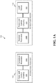
- FIGS. 1A and 1B depict diagrams of an exemplary a wireless power transfer system 100.
- the system 100 includes a wireless power transmitter 102 and a wireless power receiver 104.
- a wirelessly powered or wirelessly charged device 112 is coupled to receiver 104.
- Wirelessly powered or wirelessly charged devices 112 can include, for example, high-power devices such as electric vehicles or electronic devices such as laptops, smartphones, tablets, and other mobile electronic devices that are commonly placed on desktops, tabletops, bar tops, and other types of surfaces.
- wireless power transfer system 100 will be discussed in the context of a wireless charging system for an electric vehicle.
- system 100 can be a HRWPT system which is required to operate over a wide range of coupling factors k , load conditions (such as a battery voltage), and environmental conditions that detune the inductances of the resonators (e.g., due to spatial variations and interfering objects).
- system 100 may be required to operate with high voltages (e.g., between 360V and 800V) and high currents (e.g., between 26A and 40A) to achieve a suitable range of power (e.g., 0 to 3.7 kW, 0 to 7.7 kW, 0 to 11 kW, or 0 to 22 kW).
- high voltages e.g., between 360V and 800V
- high currents e.g., between 26A and 40A
- a suitable range of power e.g., 0 to 3.7 kW, 0 to 7.7 kW, 0 to 11 kW, or 0 to 22 kW.
- Wireless power transmitter 102 converts power from an external power source (e.g., power grid or generator) to electromagnetic energy which is transmitted between resonators 108T and 108R to wireless power receiver 104.
- Receiver 104 converts the oscillating energy received by resonator 108R to an appropriate form for use by device 112 (e.g., charging an electric vehicle battery). More specifically, the receiver power and control circuitry 110 can convert AC voltage and current from resonator 108R to DC power within appropriate voltage and current parameters for device 112.
- the transmitter power and control circuitry 106 can include circuits and components to isolate the source electronics from the power supply, so that any reflected power or signals are not coupled out through the source input terminals.
- the source power and control circuitry 106 can drive the source resonator 108S with alternating current, such as with a frequency greater than 10 kHz and less than 100 MHz (e.g., 85 kHz).
- the source power and control circuitry 106 can include, for example, power factor correction (PFC) circuitry, a transmitter controller, impedance matching circuitry, a power inverter, a DC-to-DC converter, an AC-to-DC converter, a power amplifier, or any combination thereof.
- PFC power factor correction
- the receiver power and control circuitry 110 can be designed to transform alternating current power from the receiver resonator 108R to stable direct current power suitable for powering or charging one or more devices 112.
- the receiver power and control circuitry 110 can be designed to transform an alternating current power at one frequency (e.g., 85 kHz) from resonator 108R to alternating current power at a different frequency suitable for powering or charging one or more devices 112.
- the receiver power and control circuitry 110 can include, for example, a receiver controller, impedance matching circuitry, rectification circuitry, voltage limiting circuitry, current limiting circuitry, AC-to-DC converter circuitry, DC-to-DC converter circuitry, DC-to-AC circuitry, AC-to-AC converter circuitry, and battery charge control circuitry.
- Transmitter 102 and receiver 104 can have tuning capabilities, for example, dynamic impedance matching circuits, that allow adjustment of operating points to compensate for changing environmental conditions, perturbations, and loading conditions that can affect the operation of the source and device resonators and the efficiency of the energy transfer.
- the tuning capability can be controlled automatically, and may be performed continuously, periodically, intermittently or at scheduled times or intervals. In some implementations, tuning is performed synchronously between the transmitter 102 and the receiver 104 as described in more detail below.
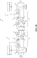
- FIG. 1B shows the power and control circuitry 106 and 110 of transmitter 102 and receiver 104 in more detail.
- transmitter 102 includes an inverter 122 powering a transmitter impedance matching network (IMN) 124 and a controller 125 that controls the operation of inverter 122 and tunes transmitter IMN 124.
- Transmitter IMN 124 is coupled to resonator coil 108T.
- Receiver 104 includes a receiver IMN 126 coupled to resonator 108R, a rectifier 128 and a controller 129 that can tune the receiver IMN 126.
- inverter 122 provides power through transmitter IMN 124 to resonator 108T.
- Resonator 108T couples oscillating electromagnetic energy to resonator 108R, with a coupling constant k .
- the energy received by resonator 108R is transferred through receiver IMN 126 to rectifier 108 which converts the energy into an appropriate form for use by device 112.
- Transmitter controller 125 and receiver controller 129 can be implemented as processors or microcontrollers. In some implementations, transmitter controller 125 and receiver controller 129 can be implemented as ASIC or FPGA controllers. Transmitter controller 125 and receiver controller 129 need not be implemented in the same form. For example, transmitter controller 125 can be implemented as a microcontroller and receiver controller 129 can be implemented as an ASIC controller.
- Transmitter 102 also includes a plurality of sensors such as voltage, current, and power sensors to measure transmitter operating parameters.
- Transmitter controller 125 can use measurements from the sensors to control the operation of the transmitter 102 and to tune the transmitter IMN 124.
- Transmitter operating parameters measured by the sensors can include, but is not limited to, inverter bus voltage (V bus ), transmitter input power, inverter AC voltage (V AC ), inverter AC current (I AC ), transmitter power factor (pf), and other voltages and currents as needed for safety checks.
- the transmitter input power is measured at an AC input to a transmitter PFC circuit.
- the transmitter input power is measured as an inverter power (P in ), as shown in FIG. 1B .
- the inverter power (P in ) is measured at the DC input of inverter 122. In some implementations, inverter power (P in ) is measured at the AC output of inverter 122.
- Transmitter power factor can be measured as the phase difference ( ⁇ ) between the inverter AC voltage (V AC ) and inverter AC current (I AC ), where the power factor is the cosine of the phase difference ( ⁇ ). In some implementations, the phase difference ( ⁇ ) can be used as a proxy for power factor. That is, transmitter controller 125 can perform operations based on the phase difference ( ⁇ ) instead of calculating an actual power factor value.
- transmitter power factor (pf) can be calculated based on equivalent resistance and reactance values as seen at the output of the inverter.
- Receiver 104 also includes a plurality of sensors such as voltage, current, and power sensors to measure receiver operating parameters.
- Receiver controller 129 can use measurements from the sensors to control the operation of the receiver 104 and to tune the receiver IMN 126.
- Receiver operating parameters measured by the sensors can include, but is not limited to, receiver output power (P out ), rectifier AC voltage, rectifier AC current, rectifier DC voltage, rectifier DC current, and other voltages and currents as needed for safety checks.
- Transmitter IMN 124 and receiver IMN 126 can each include a plurality of fixed and variable impedance matching components such as resistors, capacitors, inductors, or combinations thereof.
- Variable impedance components can be tunable reactive impedance components including, but not limited to, PWM-switched capacitors, radio frequency (RF) controlled capacitors whose effective capacitance at RF is controlled by a DC bias field, temperature-controlled capacitors, PWM-switched inductors, DC controlled inductors whose effective inductance is controlled by a bias DC field (e.g., a saturable core), temperature-controlled inductors, arrays of reactive elements switched in and out of the circuit by switches, or a combination thereof.
- RF radio frequency
- transmitter IMN 124 includes series capacitor 132, parallel capacitor 134, and the combination of capacitor 136 and inductor 138 at the output of inverter 122.
- Capacitor 136 is a variable capacitor and can include one or more variable capacitors.
- a resistive component of the transistor resonator coil 108T is represented by resistor 140.
- Receiver IMN 126 includes series capacitor 144, parallel capacitor 146, and the combination of capacitor 148 and inductor 150 at the input to rectifier 128.
- Capacitor 148 is a variable capacitor and can include one or more variable capacitors.
- a resistive component of the receiver resonator coil 108R is represented by resistor 152.
- IMNs 124 and 126 can have a wide range of circuit implementations with various components having impedances to meet the needs of a particular application.
- U.S. Patent No. 8,461,719 to Kesler et al. discloses a variety of tunable impedance network configurations, such as in FIGS. 28a-37b.
- each of the components shown in FIG. 1B may represent networks or groups of components.
- Each of the IMNs 124 and 126 include three reactances: series reactance X1 (e.g., capacitor 132 or 144), parallel reactance X2 (e.g., capacitor 134 or 146), and inverter output/rectifier input reactance X3 (combined reactance of inductor 138 or 150 with capacitor 136 or 148, respectively).
- series reactance X1 e.g., capacitor 132 or 144
- parallel reactance X2 e.g., capacitor 134 or 146
- inverter output/rectifier input reactance X3 combined reactance of inductor 138 or 150 with capacitor 136 or 148, respectively.
- the reactances X1-X3 of receiver IMN 126 mirror the corresponding reactances XI-X3 of transmitter IMN 124.
- reactance X3 is the only reactance illustrated as including a tunable reactance component, namely, capacitors 136 and 148
- reactances X1 and X2 can include tunable reactance components in addition to or in place of the tunable reactance component in reactance X3.
- IMNs 124 and 126 can be tuned by tuning any one or more of reactances X1-X3.
- components that make up reactances X1 and X3 can be balanced.
- reactances X1, X2, X3, or combinations thereof can be tuned, in some implementations, it can be advantageous to tune reactance X3.
- reactance X3 it may be possible to reduce system complexity and cost if tuning a single component in IMN is sufficient.
- the current through the X3 elements can be significantly lower than that through the tank circuit formed by X1, X2, and the resonator coil. This lower current may make implementation of tunable components more cost-effective by, for example, reducing current ratings that may be required for such components. Additionally, lower currents may reduce losses by tuning elements at X3.
- tunable reactive elements can inject harmonic noise into a HRWPT system.
- a HRWPT system may be preferable to keep this harmonic noise away from the main HRWPT resonator coils (e.g., 108T and 108R).
- Higher-harmonics injected by a tunable element at X3 may be more suppressed than those that can be generated by the inverter and rectifier and may be significantly suppressed by the rest of the HRWPT circuit before reaching the resonator coil 108T or 108R.
- the tunable element dissipates the least amount of power (theoretically zero) when the overall efficiency of the rest of the system is lowest, and the highest amount of power when the overall efficiency of the rest of system is highest. This has the desirable effect of optimizing the minimum and average efficiencies of the system while only slightly affecting the maximum efficiency.
- tuning elements at X1 or X2 can have the opposite, less desirable, effect.
- values for X1 and X2 can be determined by: 1) Determining the maximum range of reactive tuning that can be achieved based on the maximum current that flows through the circuit branches containing X3 and the current and voltage ratings of the components used in the implementation of the tunable reactive elements. For example, one may conclude that a single-stage reactive element can affect 20 ⁇ of reactive tuning.
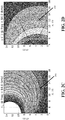
- FIGS. 2A - 2D illustrate plots related to the effects of tuning receiver X3.
- FIG. 2A illustrates that figure of merit plays a dominate role in losses at the transmitter resonator.
- FIG. 2B illustrates that quality factor ratio plays a dominate role in losses at the receiver resonator.
- FIG. 2C shows device figure of merit U d at an operating frequency of 84 kHz as a function of the change in reactance dX (in ohms) at position X3 and load resistance R L (in ohms).
- R L,eq is the loaded equivalent series resistance (ESR) (due to device electronics, such as the rectifier, and battery) of the device resonator and R d is the unloaded ESR of the device resonator.
- ESR equivalent series resistance
- FIG. 2D shows phase ⁇ (in degrees) at an operating frequency of 84 kHz as a function of the change in reactance (in ohms) and load resistance (in ohms).
- a phase ⁇ 0 means the loaded device resonator is at resonance.
- the trapezoidal dotted outline 202 in FIGS. 2C and 2D shows an operating range for a wireless power transfer receiver.
- Outline 202 in FIG. 2D shows a range of R L that would be seen for a wireless power transmission system operating at 11 kW output.
- controllers 125 and 129 can synchronously tune the IMNs 124 and 126, respectively, to maintain system 100 operations within desired operating ranges such as outline 202.
- controllers 125 and 129 perform the processes described below to synchronously tune reactance X3 of the transmitter and receiver IMNs 124 and 126 in order to safely and efficiently transfer power to a device 112 such as an electric vehicle.
- transmitter 102 and receiver 104 can communicate control data between each other.
- controllers 125 and 129 can include wireless communication interfaces to conduct electronic communications in an out-of-band communications channel. Communications between controllers 125 and 129 can include, but are not limited to, RF communications (e.g., WiFI, Bluetooth, Zigbee), optical communication, infrared communications, ultrasonic communications, or a combination thereof.
- controller 125 can tune transmitter IMN 124 to achieve a target power characteristics of transmitter 102, while controller 129 can tune receiver IMN 126 to achieve a target system efficiency.
- Transmitter controller 125 adjusts IMN 124 to achieve and maintain target power characteristics of the transmitter 102.
- Transmitter controller 125 sends input power data to receiver controller 129.
- Receiver controller 129 measures output power of the receiver 104 and, together with the input power data, calculates the efficiency of the system 100.
- Receiver controller 129 tunes the receiver IMN 126 to maximize the system efficiency. For example, receiver controller 129 can determine appropriate adjustments to receiver IMN 126 based on comparing a calculated efficiency values at two different times.
- transmitter controller 125 operates at a faster rate than receiver controller 129. That is, transmitter controller 125 can tune the transmitter IMN 124 at a faster rate than receiver controller 129 can tune the receiver IMN 126. For example, receiver controller 129 may only be permitted to tune receiver IMN 126 as fast as it receives new input power data from transmitter controller 125.
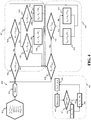
- FIG. 3 depicts a flowchart of an exemplary control process 300 for operating a wireless power transmission system.
- the example process 300 can be provided as computer-executable instructions executed using one or more processing devices (e.g., processors or microcontrollers) or computing devices.
- the process 300 may be executed by hardwired electrical circuitry, for example, as an ASIC or an FPGA controller.
- Process 300 includes two control loops 303 and 305.
- Loop 303 is performed by a transmitter 102 to tune a transmitter IMN 124 by adjusting reactance X3 to control the transmitter power.
- loop 303 is a local loop that does not require communication with other devices (e.g., receiver 104) to be performed.
- loop 303 is executed by a transmitter at between 1 - 10 kHz.
- Loop 305 is performed by a receiver 104 to tune a receiver IMN 126 based on system efficiency.
- loop 305 can employ a "perturb-and-observe" strategy to improve efficiency by adjusting reactance X3 of a receiver IMN 126 to continually improve efficiency over consecutive iterations.
- Loop 305 depends on input power data from transmitter 102 to calculate system efficiency at each iteration. In some implementations, loop 305 operates at the rate of communication between transmitter 102 and receiver 104, for example, 40 Hz.
- Block 302 lists the inputs and initial conditions for process 300 which include a variable transmitter reactance X tx (e.g., X3 of transmitter IMN 124), set to a maximum reactance value X tx,max ; a variable receiver reactance Xrx (e.g., X3 of receiver IMN 126), set to a minimum reactance value X rx,min ; a system efficiency ⁇ , initially set to zero; a transmitter reactance step size ⁇ X tx , set to an adjustment value of ⁇ ; and a receiver reactance step size ⁇ X rx , set to an adjustment value of ⁇ .
- the reactance step sizes ⁇ X tx and ⁇ X rx are constant values.
- the reactance step sizes ⁇ X tx and ⁇ X rx can be variable.
- controller 125 or controller 129 can increase or decrease the magnitude of the respective step sizes dynamically during process 300.
- Process 300 starts at step 304.
- the power of the transmitter 102 is measured.
- Transmitter controller 125 measures the input power P in , and, at step 306, compares the input power Pin to a target power level P target . If P in equals P target the process 300 proceeds to step 308 of loop 305. If Pin does not equal P target , process 300 proceeds to step 316 of loop 303.
- the target power level is set by the transmitter 102. In some implementations or some operation modes, the target power level is set by the receiver 104. For example, when in steady-state operations (e.g., normal operations apart from startup or shutdown sequences), system 100 can operate as a demand based system.
- receiver 104 can request power levels from the transmitter 102.
- Transmitter controller 125 can calculate a target input power level based on the demanded power level from the receiver 104.
- transmitter controller 125 can convert the demanded power to a target input power level that would be required to transmit the demanded power level by accounting for expected losses in the transmitter (e.g., IMN losses and inverter losses).
- transmitter controller 125 compares the input power to the target power level to determine whether the input power is less than the target power level. If Pin is less than Ptarget, then, at step 318, transmitter controller 125 sets the transmitter reactance step size ⁇ X tx , to a negative adjustment value to decrease the variable transmitter reactance X tx in step 320. If P in is not less than P target , then, at step 322, transmitter controller 125 sets the transmitter reactance step size ⁇ X tx , to a positive adjustment value to increase the variable transmitter reactance X tx in step 320.
- the input power of the transmitter e.g., the inverter power
- the magnitude of the reactance adjustment value ⁇ can be varied. For example, if the difference between P in and P target is large, for example, greater than a coarse adjustment threshold value, then the transmitter controller 125 can increase the magnitude of the reactance adjustment value ⁇ . Correspondingly, if the difference between Pin and Ptarget is small, for example, less than a fine adjustment threshold value, then the transmitter controller 125 can decrease the magnitude of the reactance adjustment value ⁇ .
- loop 303 returns to step 306, where the input power is again compared to the target power level.
- the receiver controller 129 measures the efficiency of the system 100. For example, when Pin is equal to P target , the transmitter can send data indicating the measured value of P in to the receiver 104. (It should be noted that measured transmitter power can be represented by a floating point number and, thus, may not exactly equal the target power, but may be equivalent within a predetermined tolerance.) Receiver controller 129 measures the output power of the receiver, and calculates the system efficiency ⁇ (n) at time n based on the received transmitter power data and the measured receiver output power value.
- receiver controller 129 compares the system efficiency calculated at time n, to the system efficiency calculated at a previous time n-1. If the efficiency at time n is greater than the efficiency at time n-1, then, at step 312, the variable receiver reactance X rx is adjusted by the receiver reactance step size ⁇ X rx . For example, the change in receiver reactance is added to the variable receiver reactance X rx . If the efficiency at time n is not greater than the efficiency at time n-1, then, at step 314, receiver controller 129 changes the sign of the receiver reactance step size before adjusting the variable receiver reactance X rx at step 312. For example, the value of the change in receiver reactance ⁇ can be negated.
- the direction of adjustments for the variable receiver reactance X rx is swapped when the efficiency is no longer increasing between subsequent iterations of loop 305. As illustrated in by loop 305, direction of adjustments for the variable receiver reactance X rx will then be retained in subsequent iterations of loop 305 until efficiency decreases again, thereby, maintaining a near-maximum system efficiency.
- the magnitude of the reactance adjustment value ⁇ can be varied. For example, if the efficiency at time n is less than a coarse adjustment threshold value (e.g., soon after system startup), then the receiver controller 129 can increase the magnitude of the reactance adjustment value ⁇ . Correspondingly, if the efficiency at time n is near an estimated maximum value for example, within a fine adjustment threshold of the estimated maximum value, then the receiver controller 129 can decrease the magnitude of the reactance adjustment value ⁇ .
- a coarse adjustment threshold value e.g., soon after system startup
- the receiver controller 129 can increase the magnitude of the reactance adjustment value ⁇ .
- the receiver controller 129 can decrease the magnitude of the reactance adjustment value ⁇ .
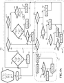
- FIG. 4 depicts a flowchart of an exemplary control process 400 for operating a wireless power transmission system.
- the example process 400 can be provided as computer-executable instructions executed using one or more processing devices (e.g., processors or microcontrollers) or computing devices.
- the process 400 may be executed by hardwired electrical circuitry, for example, as an ASIC or an FPGA controller.
- Process 400 is similar to process 300, but includes control of inverter bus voltage V bus to adjust transmitter power Pin, and measurements of and the use of inverter power factor (e.g., inverter AC voltage V AC and inverter AC current I AC phase difference ⁇ ) to tune the transmitter IMN 124.
- inverter power factor e.g., inverter AC voltage V AC and inverter AC current I AC phase difference ⁇
- Process 400 includes three control loops 401, 403, and 405. Loops 401 and 403 are performed by a transmitter 102 to tune a transmitter IMN 124 and to control the transmitter power.
- Loop 401 is a phase loop that tunes the transmitter IMN 124 by adjusting reactance X3 to achieve a target phase ⁇ relationship between the inverter AC output voltage and inverter AC output current (e.g., inverter power factor), hereinafter referred to as "inverter output phase ⁇ inv " and "target inverter output phase ⁇ target .”
- Loop 403 is a power control loop that controls and maintains the transmitter power magnitude Pin at or near the target power P target by adjusting the inverter bus voltage V bus .
- loops 401 and 403 are local loops that do not require communication with other devices (e.g., receiver 104) to be performed.
- loops 401 and 403 are executed by a transmitter at between 1 ⁇ 10 kHz.
- Loop 405 is performed by a receiver 104 to tune a receiver IMN 126 based on system efficiency. Loop 405 is similar to loop 305 of process 300. For example, loop 405 can employ a "perturb-and-observe" strategy to improve efficiency by adjusting reactance X3 of a receiver IMN 126 to continually improve efficiency over consecutive iterations. Loop 405 depends on input power data from transmitter 102 to calculate system efficiency at each iteration. In some implementations, loop 405 operates at the rate of communication between transmitter 102 and receiver 104, for example, 40 Hz.
- Block 402 lists the inputs and initial conditions for process 400 which include a variable transmitter reactance X tx (e.g., X3 of transmitter IMN 124), set to a maximum reactance value X tx,max ; a variable receiver reactance X rx (e.g., X3 of receiver IMN 126), set to a minimum reactance value X rx,min ; a system efficiency ⁇ , initially set to zero; a transmitter reactance step size ⁇ X tx , set to an adjustment value greater than zero; a receiver reactance step size ⁇ X rx , set to an adjustment value greater than zero; and a bus voltage step size ⁇ V bus set to an adjustment value greater than zero.
- a variable transmitter reactance X tx e.g., X3 of transmitter IMN 124
- a maximum reactance value X tx,max e.g., X3 of transmitter tx,max
- the reactance step sizes ⁇ X tx and ⁇ X rx and bus voltage step size ⁇ V bus are constant values. In some implementations, the reactance step sizes ⁇ X tx and ⁇ X rx and bus voltage step size ⁇ V bus can be variable. For example, controller 125 or controller 129 can increase or decrease the magnitude of the respective step sizes dynamically during process 400.
- Process 400 starts at step 404.
- transmitter controller 125 measures the inverter output phase ⁇ inv , and compares the measured inverter output phase ⁇ inv to a target inverter output phase ⁇ target . If ⁇ inv equals ⁇ target the process 400 proceeds to step 408 of loop 403. If ⁇ inv does not equal ⁇ target the process 400 proceeds to step 424 of loop 401.
- ⁇ target is slightly greater than 0 so the inverter still sees a slightly inductive load.
- transmitter controller 125 compares the inverter output phase to the target inverter output phase, at step 424, to determine whether the inverter output phase is greater than the target inverter output phase. If ⁇ inv is greater than ⁇ target , then, at step 426, transmitter controller 125 checks whether the variable transmitter reactance X tx is already at a minimum value X tx,min . If the variable transmitter reactance X tx is already at a minimum value X tx,min , then loop 401 proceeds to step 408 with no adjustment to the variable transmitter reactance X tx .
- variable transmitter reactance X tx is not at a minimum value X tx,min . If the variable transmitter reactance X tx is not at a minimum value X tx,min , then, at step 332, transmitter controller 125 decrements the variable transmitter reactance X tx by the transmitter reactance step size ⁇ X tx , and loop 401 reverts back to step 406 to reevaluate the inverter output phase.
- transmitter controller 125 checks whether the variable transmitter reactance X tx is already at a maximum value X tx,max . If the variable transmitter reactance X tx is already at a maximum value X tx,max , then loop 401 proceeds to step 408 with no adjustment to the variable transmitter reactance X tx .
- variable transmitter reactance X tx is not at a maximum value X tx,max . If the variable transmitter reactance X tx is not at a maximum value X tx,max , then, at step 420, transmitter controller 125 increments the variable transmitter reactance X tx by the transmitter reactance step size ⁇ X tx , and loop 401 reverts back to step 406 to reevaluate the inverter output phase.
- transmitter controller 125 measures the input power P in , and compares the measured input power P in to a target power level Ptarget. If Pin equals Ptarget the process 400 reverts to step 406 of loop 401. In addition, transmitter controller 125 can send data indicating the measured value of P in to the receiver 104. If Pin does not equal Ptarget, process 400 proceeds to step 418.
- the target power level is set by the transmitter 102. In some implementations or some operation modes, the target power level is set by the receiver 104. For example, when in steady-state operations (e.g., normal operations apart from startup or shutdown sequences), system 100 can operate as a demand based system.
- receiver 104 can request power levels from the transmitter 102.
- Transmitter controller 125 can calculate a target input power level based on the demanded power level from the receiver 104.
- transmitter controller 125 can convert the demanded power to a target input power level that would be required to transmit the demanded power level by accounting for expected losses in the transmitter (e.g., IMN losses and inverter losses).
- transmitter controller 125 compares the input power to the target power level to determine whether the input power is less than the target power level. If Pin is less than Ptarget, then, at step 420, transmitter controller 125 increments the inverter bus voltage V bus by the bus voltage step size ⁇ V bus , and loop 403 reverts back to step 408 to reevaluate the power of the transmitter. If Pin is not less than P target , then, at step 422, transmitter controller 125 decrements the inverter bus voltage V bus by the bus voltage step size ⁇ V bus , and loop 403 reverts back to step 408 to reevaluate the power of the transmitter.
- the magnitude of the transmitter reactance step size ⁇ X tx can be varied. For example, if the difference between ⁇ inv and ⁇ target is large, for example, greater than a coarse adjustment threshold value, then the transmitter controller 125 can increase the transmitter reactance step size ⁇ X tx . Correspondingly, if the difference between ⁇ inv and ⁇ target is small, for example, less than a fine adjustment threshold value, then the transmitter controller 125 can decrease the magnitude of the transmitter reactance step size ⁇ X tx .
- the magnitude of the bus voltage step size ⁇ V bus can be varied. For example, if the difference between Pin and Ptarget is large, for example, greater than a coarse adjustment threshold value, then the transmitter controller 125 can increase the bus voltage step size ⁇ V bus . Correspondingly, if the difference between Pin and Ptarget is small, for example, less than a fine adjustment threshold value, then the transmitter controller 125 can decrease the magnitude of the bus voltage step size ⁇ V bus .
- receiver 104 receives transmitter power data. For example, when Pin is equal to Ptarget at step 408, the transmitter 102 can send data indicating the measured value of P in to the receiver 104.
- the receiver controller 129 measures the efficiency of the system 100. Receiver controller 129 measures the output power of the receiver 104, and calculates the system efficiency ⁇ (n) at time n based on the received transmitter power data and the measured receiver output power value.
- receiver controller 129 compares the system efficiency calculated at time n, to the system efficiency calculated at a previous time n-1. If the efficiency at time n is greater than the efficiency at time n-1, then, at step 414, the variable receiver reactance X rx is adjusted by the receiver reactance step size ⁇ X rx . For example, the change in receiver reactance is added to the variable receiver reactance X rx . If the efficiency at time n is not greater than the efficiency at time n-1, then, at step 416, receiver controller 129 changes the sign of the receiver reactance step size before adjusting the variable receiver reactance X rx at step 414. For example, the value of the receiver reactance step size ⁇ X rx can be negated.
- the direction of adjustments for the variable receiver reactance X rx is swapped when the efficiency is no longer increasing between subsequent iterations of loop 405. As illustrated in by loop 405, direction of adjustments for the variable receiver reactance X rx will then be retained in subsequent iterations of loop 405 until efficiency decreases again, thereby, maintaining a near-maximum system efficiency.
- the magnitude of the receiver reactance step size can be varied. For example, if the efficiency at time n is less than a coarse adjustment threshold value (e.g., soon after system startup), then the receiver controller 129 can increase the magnitude of the receiver reactance step size ⁇ X rx . Correspondingly, if the efficiency at time n is near an estimated maximum value for example, within a fine adjustment threshold of the estimated maximum value, then the receiver controller 129 can decrease the magnitude of the receiver reactance step size ⁇ X rx .
- a coarse adjustment threshold value e.g., soon after system startup
- the receiver controller 129 can increase the magnitude of the receiver reactance step size ⁇ X rx .
- the receiver controller 129 can decrease the magnitude of the receiver reactance step size ⁇ X rx .
- FIGS. 5A - 5C depicts a flowchart of an exemplary control processes 500a, 500b, and 500c for operating a wireless power transmission system.
- the processes 500a, 500b, and 500c can be provided as computer-executable instructions executed using one or more processing devices (e.g., processors or microcontrollers) or computing devices.
- the processes 500a, 500b, and 500c may be executed by hardwired electrical circuitry, for example, as an ASIC or an FPGA controller.
- Processes 500a, 500b, and 500c are related to processes 300 and 400, but include additional steps that evaluate and control additional system parameters to operate a wireless power transmission system.
- process 500a includes portions that are be performed by a wireless power transmitter 102 (e.g., transmitter controller 125) and portions that are performed by a wireless power receiver 104 (e.g., receiver controller 129).
- Process 500a includes three control loops 501a, 503a, and 505. Loops 501a and 503a are performed by a transmitter 102 to tune a transmitter IMN 124 and to control the transmitter power.
- Loop 501a is a phase loop that tunes the transmitter IMN 124 by adjusting reactance X3 to achieve a target inverter output phase ⁇ target .
- Loop 501a also includes safety checks to ensure that current, voltage, or other device limitations are not exceeded.
- Loop 503a is a power control loop that controls and maintains the transmitter power magnitude P in at or near the target power Ptarget by adjusting the inverter bus voltage Vbus. Loop 503a also incorporates adjustments to inverter frequency f inv to control transmitter power.
- loops 501a and 503a are local loops that do not require communication with other devices (e.g., receiver 104) to be performed.
- loops 501a and 503a are executed by a transmitter at between 1 - 10 kHz.
- Loop 505 is performed by a receiver 104 to tune a receiver IMN 126 based on system efficiency. Loop 505 is the same as loop 405 of process 400 the operation of which is described above.
- Block 502 lists the inputs and initial conditions for process 500a which include a variable transmitter reactance X tx (e.g., X3 of transmitter IMN 124), set to a maximum reactance value X tx,max ; a variable receiver reactance X rx (e.g., X3 of receiver IMN 126), set to a minimum reactance value X rx,min ; an inverter frequency f inv , set to a maximum frequency f inv,max ; a system efficiency ⁇ , initially set to zero; a transmitter reactance step size ⁇ X tx , set to an adjustment value greater than zero; a receiver reactance step size ⁇ X rx , set to an adjustment value greater than zero; an inverter frequency step size ⁇ f inv set to an adjustment value greater than zero; and a bus voltage step size ⁇ V bus set to an adjustment value greater than zero.
- a variable transmitter reactance X tx e.g., X3
- the reactance step sizes ⁇ X tx and ⁇ X rx , bus voltage step size ⁇ V bus , and inverter frequency step size ⁇ f inv are constant values.
- the reactance step sizes ⁇ X tx and ⁇ X rx , bus voltage step size ⁇ V bus , and inverter frequency step size ⁇ f inv can be variable.
- controller 125 or controller 129 can increase or decrease the magnitude of the respective step sizes dynamically during process 500a.
- Process 500a starts at step 504.
- transmitter controller 125 performs several checks while tuning the inverter frequency in step 508.
- Transmitter controller 125 compares the measured input power Pin to a target power level P target , the measured inverter output phase ⁇ inv to an inverter output phase limit ⁇ limit (e.g., 45 degrees), and the inverter frequency f inv to the minimum inverter frequency f inv,min .
- transmitter controller 125 decrements the inverter frequency f inv by inverter frequency step size ⁇ f inv at step 508. If any of the comparisons are false, the process 500a proceeds to step 510 of loop 501a.
- transmitter controller 125 compares the inverter output phase to the target inverter output phase, at step 536, to determine whether the inverter output phase is greater than the target inverter output phase. If ⁇ inv is greater than ⁇ target , then, at step 538, transmitter controller 125 performs several additional checks. At step 538, transmitter controller 125 checks whether the variable transmitter reactance X tx is already at a minimum value X tx,min ; whether P in is greater than P target , or whether a safety check has failed.
- the safety check can be, for example, an over voltage or over current check.
- loop 501a proceeds to an additional safety check at step 540.
- the safety check at step 540 can be the same safety check as performed at step 538, for example, to determine whether the safety check at step 538 was the check that caused the transmitter controller 125 to proceed to step 540. If so, then transmitter controller 125 increments the variable transmitter reactance X tx by the transmitter reactance step size ⁇ X tx , and loop 501a reverts back to step 506. If not, then loop 501a proceeds to step 512 of loop 503a to adjust the transmitter power. If all of the checks at step 538 are false, then transmitter controller 125 decrements the variable transmitter reactance X tx by the transmitter reactance step size ⁇ X tx , and loop 501a reverts back to step 506.
- transmitter controller 125 checks whether the variable transmitter reactance X tx is already at a maximum value X tx,max . If the variable transmitter reactance X tx is already at a maximum value X tx,max , then loop 501a issue a fault condition 548. If the variable transmitter reactance X tx is not at a maximum value X tx,max , then, at step 550, transmitter controller 125 increments the variable transmitter reactance X tx by the transmitter reactance step size ⁇ X tx , and loop 501a reverts back to step 506.
- transmitter controller 125 measures the input power P in , and compares the measured input power P in to a target power level P target . If Pin equals Ptarget the process 500a reverts to step 506. In addition, transmitter controller 125 can send data indicating the measured value of P in to the receiver 104. If P in does not equal P target process 500a proceeds to step 522. At step 522, transmitter controller 125 compares the input power to the target power level to determine whether the input power is greater than the target power level.
- transmitter controller 125 increments the inverter bus voltage V bus by the bus voltage step size ⁇ V bus , and loop 503a reverts back to step 506. If Pin is greater than Ptarget, then, at step 524, transmitter controller 125 checks the bus voltage. If the bus voltage V bus is greater than a minimum bus voltage V bus,min , then, at step 532, transmitter controller 125 decrements the inverter bus voltage V bus by the bus voltage step size ⁇ V bus , and loop 503a reverts back to step 506.
- the transmitter controller 125 reduces the transmitter power by adjusting either the variable transmitter reactance X tx or the inverter frequency f inv .
- transmitter controller 125 checks whether the variable transmitter reactance X tx is already at a maximum value X tx,max . If the variable transmitter reactance X tx is not at a maximum value X tx,max , then, at step 530, transmitter controller 125 increments the variable transmitter reactance X tx by the transmitter reactance step size ⁇ X tx , and loop 501 reverts back to step 506.
- variable transmitter reactance X tx is already at a maximum value X tx,max . If the variable transmitter reactance X tx is already at a maximum value X tx,max , then the transmitter controller 125 checks whether the inverter frequency f inv is less than a maximum inverter frequency f inv,max at step 527. If the inverter frequency f inv is already at a maximum value f inv,max , then loop 503a reverts to step 506 with no adjustments to the bus voltage V bus , the variable transmitter reactance X tx , or the inverter frequency f inv .
- transmitter controller 125 increments the inverter frequency f inv by the frequency step size ⁇ f inv , and loop 503a reverts back to step 506.
- process 500b differs from process 500a by monitoring and controlling inverter phase shift ⁇ inv instead of inverter frequency f inv .
- inverter power can be controlled by adjusting the internal phase shift ⁇ inv between bridge circuits in the inverter.
- a phase shift ⁇ inv of zero degrees may produce a minimum (e.g., zero) inverter power
- a phase shift ⁇ inv of 180 degrees may produce a maximum inverter power for a given bus voltage V bus .
- steps 560, 562, 564, 566, and 568 replace steps 502, 506, 508, 527, and 528 of process 500a, respectively.
- Process 500b includes portions that are be performed by a wireless power transmitter 102 (e.g., transmitter controller 125) and portions that are performed by a wireless power receiver 104 (e.g., receiver controller 129).
- Process 500b includes three control loops 501b, 503b, and 505. Loops 501b and 503b are performed by a transmitter 102 to tune a transmitter IMN 124 and to control the transmitter power.
- Loop 501b is a phase loop that tunes the transmitter IMN 124 by adjusting reactance X3 to achieve a target inverter output phase ⁇ target .
- Loop 501b also includes safety checks to ensure that current, voltage, or other device limitations are not exceeded.
- Loop 503b is a power control loop that controls and maintains the transmitter power magnitude P in at or near the target power P target by adjusting the inverter bus voltage V bus . Loop 503b also incorporates adjustments to inverter phase shift ⁇ inv to control transmitter power.
- loops 501b and 503b are local loops that do not require communication with other devices (e.g., receiver 104) to be performed.
- loops 501b and 503b are executed by a transmitter at between 1 - 10 kHz.
- Loop 505 is performed by a receiver 104 to tune a receiver IMN 126 based on system efficiency. Loop 505 is the same as loop 405 of process 400 the operation of which is described above.
- Block 560 lists the inputs and initial conditions for process 500b which include a variable transmitter reactance X tx (e.g., X3 of transmitter IMN 124), set to a maximum reactance value X tx,max ; a variable receiver reactance X rx (e.g., X3 of receiver IMN 126), set to a minimum reactance value X rx,min ; an inverter phase shift ⁇ inv , set to a minimum phase shift ⁇ inv,min ; a system efficiency ⁇ , initially set to zero; a transmitter reactance step size ⁇ X tx , set to an adjustment value greater than zero; a receiver reactance step size ⁇ X rx , set to an adjustment value greater than zero; an inverter phase shift step size ⁇ inv set to an adjustment value greater than zero; and a bus voltage step size ⁇ V bus set to an adjustment value greater than zero.
- a variable transmitter reactance X tx e.g.,
- the reactance step sizes ⁇ X tx and ⁇ X rx , bus voltage step size ⁇ V bus , and inverter phase shift step size ⁇ inv are constant values.
- the reactance step sizes ⁇ X tx , and ⁇ X rx , bus voltage step size ⁇ V bus , and inverter phase shift step size ⁇ inv can be variable.
- controller 125 or controller 129 can increase or decrease the magnitude of the respective step sizes dynamically during process 500b.
- Process 500b starts at step 504.
- transmitter controller 125 performs several checks while tuning the inverter phase shift in step 564.
- Transmitter controller 125 compares the measured input power P in to a target power level P target and the inverter phase shift ⁇ inv to a phase shift limit ⁇ limit (e.g., 180 degrees). When all of the comparisons in step 564 are true, then transmitter controller 125 increments the inverter phase shift ⁇ inv by inverter phase shift step size ⁇ inv at step 564. If any of the comparisons are false, at step 582, transmitter controller 125 checks whether the inverter phase shift ⁇ inv is less than the phase shift limit ⁇ limit . If so, process 500b proceeds to step 566. If not, process 500b proceeds to step 510 of loop 501b.
- a phase shift limit ⁇ limit e.g. 180 degrees
- transmitter controller 125 compares the inverter output phase to the target inverter output phase, at step 536, to determine whether the inverter output phase is greater than the target inverter output phase. If ⁇ inv is greater than ⁇ target , then, at step 538, transmitter controller 125 performs several additional checks. At step 538, transmitter controller 125 checks whether the variable transmitter reactance X tx is already at a minimum value X tx,min ; whether P in is greater than P target , or whether a safety check has failed.
- the safety check can be, for example, an over voltage or over current check.
- loop 501b proceeds to an additional safety check at step 540.
- the safety check at step 540 can be the same safety check as performed at step 538, for example, to determine whether the safety check at step 538 was the check that caused the transmitter controller 125 to proceed to step 540. If so, then transmitter controller 125 increments the variable transmitter reactance X tx by the transmitter reactance step size ⁇ X tx , and loop 501b reverts back to step 562. If not, then loop 501b proceeds to step 512 of loop 503b to adjust the transmitter power. If all of the checks at step 538 are false, then transmitter controller 125 decrements the variable transmitter reactance X tx by the transmitter reactance step size ⁇ X tx , and loop 501b reverts back to step 562.
- transmitter controller 125 checks whether the variable transmitter reactance X tx is already at a maximum value X tx,max . If the variable transmitter reactance X tx is already at a maximum value X tx,max , then loop 501b issue a fault condition 548. If the variable transmitter reactance X tx is not at a maximum value X tx,max , then, at step 550, transmitter controller 125 increments the variable transmitter reactance X tx by the transmitter reactance step size ⁇ X tx , and loop 501b reverts back to step 562.
- transmitter controller 125 measures the input power P in , and compares the measured input power P in to a target power level P target . If P in equals P target the process 500b reverts to step 562. In addition, transmitter controller 125 can send data indicating the measured value of P in to the receiver 104. If P in does not equal P target , process 500b proceeds to step 522. At step 522, transmitter controller 125 compares the input power to the target power level to determine whether the input power is greater than the target power level.
- transmitter controller 125 increments the inverter bus voltage V bus by the bus voltage step size ⁇ V bus , and loop 503b reverts back to step 562. If P in is greater than P target , then, at step 524, transmitter controller 125 checks the bus voltage. If the bus voltage V bus is greater than a minimum bus voltage V bus,min , then, at step 532, transmitter controller 125 decrements the inverter bus voltage V bus by the bus voltage step size ⁇ V bus , and loop 503b reverts back to step 562.
- the transmitter controller 125 reduces the transmitter power by adjusting either the variable transmitter reactance X tx or the inverter phase shift ⁇ inv .
- transmitter controller 125 checks whether the variable transmitter reactance X tx is already at a maximum value X tx,max . If the variable transmitter reactance X tx is not at a maximum value X tx,max , then, at step 530, transmitter controller 125 increments the variable transmitter reactance X tx by the transmitter reactance step size ⁇ X tx , and loop 501b reverts back to step 562.
- variable transmitter reactance X tx is already at a maximum value X tx,max , then the transmitter controller 125 checks whether the inverter phase shift ⁇ inv is greater than a minimum inverter phase shift ⁇ inv,min at step 566. If the inverter phase shift ⁇ inv is already at a minimum value ⁇ inv,min , then loop 503b reverts to step 562 with no adjustments to the bus voltage V bus , the variable transmitter reactance X tx , or the inverter phase shift ⁇ inv .
- transmitter controller 125 decrements the inverter phase shift ⁇ inv by the phase shift step size ⁇ inv , and loop 503b reverts back to step 562.
- Process 500c combines aspects of processes 500a and 500b.
- Process 500c includes portions that are be performed by a wireless power transmitter 102 (e.g., transmitter controller 125) and portions that are performed by a wireless power receiver 104 (e.g., receiver controller 129).
- Process 500c includes three control loops 501c, 503c, and 505. Loops 501c and 503c are performed by a transmitter 102 to tune a transmitter IMN 124 and to control the transmitter power.
- Loop 501c is a phase loop that tunes the transmitter IMN 124 by adjusting reactance X3 to achieve a target inverter output phase ⁇ target .
- Loop 501b also includes safety checks to ensure that current, voltage, or other device limitations are not exceeded.
- Loop 503c is a power control loop that controls and maintains the transmitter power magnitude Pin at or near the target power Ptarget by adjusting the inverter bus voltage V bus .
- Loop 503c also incorporates adjustments to both inverter frequency f inv and inverter phase shift ⁇ inv to control transmitter power.
- loops 501c and 503c are local loops that do not require communication with other devices (e.g., receiver 104) to be performed.
- loops 501c and 503c are executed by a transmitter at between 1 - 10 kHz.
- Loop 505 is performed by a receiver 104 to tune a receiver IMN 126 based on system efficiency. Loop 505 is the same as loop 405 of process 400 the operation of which is described above.
- Block 580 represents the inputs and initial conditions for process 500c which include a variable transmitter reactance X tx (e.g., X3 of transmitter IMN 124), set to a maximum reactance value X tx,max ; a variable receiver reactance X rx (e.g., X3 of receiver IMN 126), set to a minimum reactance value X rx,min ; an inverter frequency f inv , set to a maximum frequency f inv,max ; an inverter phase shift ⁇ inv , set to a minimum phase shift ⁇ inv,min ; a system efficiency ⁇ , initially set to zero; a transmitter reactance step size ⁇ X tx , set to an adjustment value greater than zero; a receiver reactance step size ⁇ X rx , set to an adjustment value greater than zero; an inverter frequency step size ⁇ f inv set to an adjustment value greater than zero; an inverter phase shift step size ⁇ inv set to an
- the reactance step sizes ⁇ X tx and ⁇ X rx , bus voltage step size ⁇ V bus , inverter frequency step size ⁇ f inv , and inverter phase shift step size ⁇ inv are constant values.
- the reactance step sizes ⁇ X tx and ⁇ X rx , bus voltage step size ⁇ V bus , inverter frequency step size ⁇ f inv , and inverter phase shift step size ⁇ inv can be variable.
- controller 125 or controller 129 can increase or decrease the magnitude of the respective step sizes dynamically during process 500c.
- Process 500c starts at step 504.
- transmitter controller 125 performs several checks while tuning the inverter phase shift in step 564.
- Transmitter controller 125 compares the measured input power P in to a target power level P target and the inverter phase shift ⁇ inv to a phase shift limit ⁇ limit (e.g., 180 degrees). When all of the comparisons in step 564 are true, then transmitter controller 125 increments the inverter phase shift ⁇ inv by inverter phase shift step size ⁇ inv at step 564. If any of the comparisons are false, at step 582, transmitter controller 125 checks whether the inverter phase shift ⁇ inv is less than the phase shift limit ⁇ limit . If so, process 500c proceeds to step 566. If not, process 500c proceeds to step 506.
- a phase shift limit ⁇ limit e.g. 180 degrees
- transmitter controller 125 performs several checks while tuning the inverter frequency in step 508.
- Transmitter controller 125 compares the measured input power P in to a target power level P target , the measured inverter output phase ⁇ inv to an inverter output phase limit ⁇ limit (e.g., 45 degrees), and the inverter frequency f inv to the minimum inverter frequency f inv,min .
- transmitter controller 125 decrements the inverter frequency f inv by inverter frequency step size ⁇ f inv at step 508. If any of the comparisons are false, the process 500a proceeds to step 510 of loop 501c.
- transmitter controller 125 compares the inverter output phase to the target inverter output phase, at step 536, to determine whether the inverter output phase is greater than the target inverter output phase. If ⁇ inv is greater than ⁇ target , then, at step 538, transmitter controller 125 performs several additional checks. At step 538, transmitter controller 125 checks whether the variable transmitter reactance X tx is already at a minimum value X tx,min ; whether P in is greater than P target , or whether a safety check has failed.
- the safety check can be, for example, an over voltage or over current check.
- loop 501c proceeds to an additional safety check at step 540.
- the safety check at step 540 can be the same safety check as performed at step 538, for example, to determine whether the safety check at step 538 was the check that caused the transmitter controller 125 to proceed to step 540. If so, then transmitter controller 125 increments the variable transmitter reactance X tx by the transmitter reactance step size ⁇ X tx , and loop 501c reverts back to step 562. If not, then loop 501c proceeds to step 512 of loop 503c to adjust the transmitter power. If all of the checks at step 538 are false, then transmitter controller 125 decrements the variable transmitter reactance X tx by the transmitter reactance step size ⁇ X tx , and loop 501c reverts back to step 562.
- transmitter controller 125 checks whether the variable transmitter reactance X tx is already at a maximum value X tx,max . If the variable transmitter reactance X tx is already at a maximum value X tx,max , then loop 501c issue a fault condition 548. If the variable transmitter reactance X tx is not at a maximum value X tx,max , then, at step 550, transmitter controller 125 increments the variable transmitter reactance X tx by the transmitter reactance step size ⁇ X tx , and loop 501c reverts back to step 562.
- transmitter controller 125 measures the input power P in , and compares the measured input power P in to a target power level P target . If Pin equals Ptarget the process 500c reverts to step 562. In addition, transmitter controller 125 can send data indicating the measured value of P in to the receiver 104. If P in does not equal P target process 500c proceeds to step 522. At step 522, transmitter controller 125 compares the input power to the target power level to determine whether the input power is greater than the target power level.
- transmitter controller 125 increments the inverter bus voltage V bus by the bus voltage step size ⁇ V bus , and loop 503c reverts back to step 562. If Pin is greater than Ptarget, then, at step 524, transmitter controller 125 checks the bus voltage. If the bus voltage V bus is greater than a minimum bus voltage V bus,min , then, at step 532, transmitter controller 125 decrements the inverter bus voltage V bus by the bus voltage step size ⁇ V bus , and loop 503c reverts back to step 562.
- the transmitter controller 125 reduces the transmitter power by adjusting either the variable transmitter reactance X tx , the inverter frequency f inv , or the inverter phase shift ⁇ inv .
- transmitter controller 125 checks whether the variable transmitter reactance X tx is already at a maximum value X tx,max .
- variable transmitter reactance X tx is not at a maximum value X tx,max . If the variable transmitter reactance X tx is not at a maximum value X tx,max , then, at step 530, transmitter controller 125 increments the variable transmitter reactance X tx by the transmitter reactance step size ⁇ X tx , and loop 501c reverts back to step 562.
- the transmitter controller 125 checks whether the inverter frequency f inv is less than a maximum inverter frequency f inv,max at step 527. If the inverter frequency f inv is not already at a maximum value f inv,max , then, at step 528, transmitter controller 125 increments the inverter frequency f inv by the frequency step size ⁇ f inv , and loop 503c reverts back to step 562.
- the transmitter controller 125 checks whether the inverter phase shift ⁇ inv is greater than a minimum inverter phase shift ⁇ inv,min at step 566. If the inverter phase shift ⁇ inv is already at a minimum value ⁇ inv,min , then loop 503c reverts to step 562 with no adjustments to the bus voltage V bus , the variable transmitter reactance X tx , or the inverter phase shift ⁇ inv .
- transmitter controller 125 decrements the inverter phase shift ⁇ inv by the phase shift step size ⁇ inv , and loop 503c reverts back to step 562.
- the magnitude of the transmitter reactance step size ⁇ X tx can be varied. For example, if the difference between ⁇ inv and ⁇ target is large, for example, greater than a coarse adjustment threshold value, then the transmitter controller 125 can increase the transmitter reactance step size ⁇ X tx . Correspondingly, if the difference between ⁇ inv and ⁇ target is small, for example, less than a fine adjustment threshold value, then the transmitter controller 125 can decrease the magnitude of the transmitter reactance step size ⁇ X tx .
- the magnitude of the bus voltage step size ⁇ V bus can be varied. For example, if the difference between P in and P target is large, for example, greater than a coarse adjustment threshold value, then the transmitter controller 125 can increase the bus voltage step size ⁇ V bus . Correspondingly, if the difference between P in and P target is small, for example, less than a fine adjustment threshold value, then the transmitter controller 125 can decrease the magnitude of the bus voltage step size ⁇ V bus .
- the magnitude of the inverter frequency step size ⁇ f inv can be varied. For example, if the difference between Pin and Ptarget, in step 506, is large, for example, greater than a coarse adjustment threshold value, then the transmitter controller 125 can increase the inverter frequency step size ⁇ f inv . Correspondingly, if the difference between Pin and Ptarget is small, for example, less than a fine adjustment threshold value, then the transmitter controller 125 can decrease the magnitude of inverter frequency step size ⁇ f inv .
- the magnitude of the inverter phase shift step size ⁇ inv can be varied. For example, if the difference between Pin and Ptarget, in step 562, is large, for example, greater than a coarse adjustment threshold value, then the transmitter controller 125 can increase the inverter phase shift step size ⁇ inv . Correspondingly, if the difference between Pin and Ptarget is small, for example, less than a fine adjustment threshold value, then the transmitter controller 125 can decrease the magnitude of inverter phase shift step size ⁇ inv .
- Position Z is the separation distance between the receiver resonator coil and the transmitter resonator coil along the vertical Z-axis.
- FIG. 6A depicts a flowchart of an exemplary startup process 600 for a wireless power transmission control system.
- the process 600 can be provided as computer-executable instructions executed using one or more processing devices (e.g., processors or microcontrollers) or computing devices.
- the process 600 may be executed by hardwired electrical circuitry, for example, as an ASIC or an FPGA controller.
- Some portions of process 600 can be be performed by a wireless power transmitter 102 (e.g., transmitter controller 125) and some portions of process 600 can be performed by a wireless power receiver 104 (e.g., receiver controller 129).
- Block 602 lists the inputs and initial conditions for the system startup process 600 which include a power factor correction (PFC) stage of a transmitter set to OFF; an inverter pulse width modulation (PWM) set to OFF; an inverter frequency f inv set to a maximum frequency f inv,max ; a variable transmitter reactance X tx (e.g., X3 of transmitter IMN 124) set to a maximum reactance value X tx,max ; and a variable receiver reactance Xrx (e.g., X3 of receiver IMN 126) set to a maximum reactance value X rx,max .
- PFC power factor correction
- PWM pulse width modulation
- the startup process 600 begins at step 604, the PFC is turned ON and bus voltage V bus is brought to minimum bus voltage V bus,min .
- the inverter PWMs are turned ON.
- variable receiver reactance X rx is adjusted to minimum receiver reactance X rx,min .
- inverter frequency f inv is adjusted to target inverter frequency f inv,target .
- the system begins steady state operations, e.g., according to one of processes 300, 400, 500a, 500b, or 500c.
- FIG. 6A depicts a flowchart of an exemplary shutdown process 601 for a wireless power transmission control system m.
- the process 601 can be provided as computer-executable instructions executed using one or more processing devices (e.g., processors or microcontrollers) or computing devices.
- the process 601 may be executed by hardwired electrical circuitry, for example, as an ASIC or an FPGA controller.
- Some portions of process 601 can be performed by a wireless power transmitter 102 (e.g., transmitter controller 125) and some portions of process 601 can be performed by a wireless power receiver 104 (e.g., receiver controller 129).
- Shutdown process 601 begins, at step 612, with the system in steady state operation, e.g., according to one of processes 300, 400, 500a, 500b, or 500c.
- variable receiver reactance X rx is brought to minimum receiver reactance X rx,min .
- variable transmitter reactance X tx is brought to maximum transmitter reactance X tx,max , and at step 618, bus voltage V bus is brought to minimum bus voltage V bus,min .
- steps 616 and 618 can be performed directly by a transmitter. In some implementations, steps 616 and 618 can be performed indirectly.
- steps 616 and 618 will be performed automatically as part of the steady state operations of processes 500a, 500b, and 500c (steps 524, 532, 526, and 530) simply be adjusting the target power Ptarget to a shutdown value P shutdown at step 615.
- P shutdown can be zero or near zero.
- the variable transmitter reactance X tx is brought to maximum transmitter reactance X tx,max and bus voltage V bus is brought to minimum bus voltage V bus,min by the steady state transmitter operations process.
- the PFC is turned OFF and V bus is brought to 0 V.
- the inverter PWMs are turned off.
- the wireless communication between the receiver and transmitter may be remain on or be turned off after power transmission is secured.
- devices that can receive power using the devices, components, and methods disclosed herein can include a wide range of electrical devices, and are not limited to those devices described for illustrative purposes herein.
- any portable electronic device such as a cell phone, keyboard, mouse, radio, camera, mobile handset, headset, watch, headphones, dongles, multifunction cards, food and drink accessories, and the like, and any workspace electronic devices such as printers, clocks, lamps, headphones, external drives, projectors, digital photo frames, additional displays, and the like, can receive power wirelessly using the devices, components, and methods disclosed herein.
- any electrical device such as electric or hybrid vehicles, motorized wheel chairs, scooters, power tools, and the like, can receive power wirelessly using the devices, components, and methods disclosed herein.
- the devices, components, and methods disclosed herein may be used for applications outside of wireless power transfer.
- circuits such as capacitors, inductors, resistors
- circuits are referred to as circuit “components” or “elements.”
- the disclosure also refers to series and parallel combinations of these components or elements as elements, networks, topologies, circuits, and the like. More generally, however, where a single component or a specific network of components is described herein, it should be understood that alternative embodiments may include networks for elements, alternative networks, and/or the like.
- the equalities and inequalities when referring to comparisons between transmitter or receiver operating parameters is not intended to require exact equivalence of values, but instead refers to an equivalence of values that are within a threshold or a tolerance of one another.
- measured values such as powers, voltages, currents, and phases can be represented and stored as floating point numbers.
- exact equivalence may be unlikely deepening on the precision of the measurements. Therefore, equivalence between such numbers and target values refers to equivalence within a threshold range, for example, equivalence within a tolerance of ⁇ 1%, ⁇ 2%, ⁇ 5%, or ⁇ 10% of the target value.
- inequalities may require a measured value to be greater or less than a target value by an additional ⁇ 1%, ⁇ 2%, ⁇ 5%, or ⁇ 10% of the target value.
- Coupled when referring to circuit or system components is used to describe an appropriate, wired or wireless, direct or indirect, connection between one or more components through which information or signals can be passed from one component to another.
- direct connection refers to a direct connection between two elements where the elements are connected with no intervening active elements between them.
- electrically connected refers to an electrical connection between two elements where the elements are connected such that the elements have a common potential.
- a connection between a first component and a terminal of a second component means that there is a path between the first component and the terminal that does not pass through the second component.
- Implementations of the subject matter and the operations described in this specification can be realized in digital electronic circuitry, or in computer software, firmware, or hardware, including the structures disclosed in this specification and their structural equivalents, or in combinations of one or more of them. Implementations of the subject matter described in this specification can be realized using one or more computer programs, i.e., one or more modules of computer program instructions, encoded on computer storage medium for execution by, or to control the operation of, data processing apparatus. Alternatively or in addition, the program instructions can be encoded on an artificially generated propagated signal, e.g., a machine-generated electrical, optical, or electromagnetic signal that is generated to encode information for transmission to suitable receiver apparatus for execution by a data processing apparatus.
- an artificially generated propagated signal e.g., a machine-generated electrical, optical, or electromagnetic signal that is generated to encode information for transmission to suitable receiver apparatus for execution by a data processing apparatus.
- a computer storage medium can be, or be included in, a computer-readable storage device, a computer-readable storage substrate, a random or serial access memory array or device, or a combination of one or more of them.
- a computer storage medium is not a propagated signal; a computer storage medium can be a source or destination of computer program instructions encoded in an artificially generated propagated signal.
- the computer storage medium can also be, or be included in, one or more separate physical components or media (e.g., multiple CDs, disks, or other storage devices).
- the operations described in this specification can be implemented as operations performed by a data processing apparatus on data stored on one or more computer-readable storage devices or received from other sources.
- the term "data processing apparatus” encompasses all kinds of apparatus, devices, and machines for processing data, including by way of example a programmable processor, a computer, a system on a chip, or multiple ones, or combinations, of the foregoing.
- the apparatus can include special purpose logic circuitry, e.g., an FPGA (field programmable gate array) or an ASIC (application-specific integrated circuit).
- the apparatus can also include, in addition to hardware, code that creates an execution environment for the computer program in question, e.g., code that constitutes processor firmware, a protocol stack, a database management system, an operating system, a cross-platform runtime environment, a virtual machine, or a combination of one or more of them.
- the apparatus and execution environment can realize various different computing model infrastructures, such as web services, distributed computing and grid computing infrastructures.
- a computer program (also known as a program, software, software application, script, or code) can be written in any form of programming language, including compiled or interpreted languages, declarative or procedural languages, and it can be deployed in any form, including as a stand-alone program or as a module, component, subroutine, object, or other unit suitable for use in a computing environment.
- a computer program may, but need not, correspond to a file in a file system.
- a program can be stored in a portion of a file that holds other programs or data (e.g., one or more scripts stored in a markup language document), in a single file dedicated to the program in question, or in multiple coordinated files (e.g., files that store one or more modules, sub-programs, or portions of code).
- a computer program can be deployed to be executed on one computer or on multiple computers that are located at one site or distributed across multiple sites and interconnected by a communication network.
- the processes and logic flows described in this specification can be performed by one or more programmable processors executing one or more computer programs to perform actions by operating on input data and generating output.
- the processes and logic flows can also be performed by, and apparatus can also be implemented as, special purpose logic circuitry, e.g., an FPGA (field programmable gate array) or an ASIC (application-specific integrated circuit).
- processors suitable for the execution of a computer program include, by way of example, both general and special purpose microprocessors, and any one or more processors of any kind of digital computer.
- a processor will receive instructions and data from a read-only memory or a random access memory or both.
- Elements of a computer can include a processor for performing actions in accordance with instructions and one or more memory devices for storing instructions and data.
- a computer will also include, or be operatively coupled to receive data from or transfer data to, or both, one or more mass storage devices for storing data, e.g., magnetic, magneto-optical disks, or optical disks.
- mass storage devices for storing data, e.g., magnetic, magneto-optical disks, or optical disks.
- a computer need not have such devices.
- a computer can be embedded in another device, e.g., a wireless power transmitter or receiver or a wirelessly charged or powered device such as a vehicle, a mobile telephone, a personal digital assistant (PDA), a mobile audio or video player, a game console, or a Global Positioning System (GPS) receiver, to name just a few.
- Devices suitable for storing computer program instructions and data include all forms of non-volatile memory, media and memory devices, including by way of example semiconductor memory devices, e.g., EPROM, EEPROM, and flash memory devices; magnetic disks, e.g., internal hard disks or removable disks; magneto-optical disks; and CD-ROM and DVD-ROM disks.
- the processor and the memory can be supplemented by, or incorporated in, special purpose logic circuitry.
Applications Claiming Priority (3)
| Application Number | Priority Date | Filing Date | Title |
|---|---|---|---|
| US201662290325P | 2016-02-02 | 2016-02-02 | |
| US201662379618P | 2016-08-25 | 2016-08-25 | |
| EP17154475.2A EP3203604B1 (en) | 2016-02-02 | 2017-02-02 | Controlling wireless power transfer systems |
Related Parent Applications (1)
| Application Number | Title | Priority Date | Filing Date |
|---|---|---|---|
| EP17154475.2A Division EP3203604B1 (en) | 2016-02-02 | 2017-02-02 | Controlling wireless power transfer systems |
Publications (2)
| Publication Number | Publication Date |
|---|---|
| EP3462574A1 EP3462574A1 (en) | 2019-04-03 |
| EP3462574B1 true EP3462574B1 (en) | 2021-11-17 |
Family
ID=57963085
Family Applications (2)
| Application Number | Title | Priority Date | Filing Date |
|---|---|---|---|
| EP18205934.5A Active EP3462574B1 (en) | 2016-02-02 | 2017-02-02 | Controlling wireless power transfer systems |
| EP17154475.2A Active EP3203604B1 (en) | 2016-02-02 | 2017-02-02 | Controlling wireless power transfer systems |
Family Applications After (1)
| Application Number | Title | Priority Date | Filing Date |
|---|---|---|---|
| EP17154475.2A Active EP3203604B1 (en) | 2016-02-02 | 2017-02-02 | Controlling wireless power transfer systems |
Country Status (8)
| Country | Link |
|---|---|
| US (2) | US10263473B2 (ja) |
| EP (2) | EP3462574B1 (ja) |
| JP (1) | JP6956728B2 (ja) |
| KR (1) | KR20180101618A (ja) |
| CN (1) | CN109075613B (ja) |
| AU (1) | AU2017214479A1 (ja) |
| CA (1) | CA3012325A1 (ja) |
| WO (1) | WO2017136491A1 (ja) |
Families Citing this family (50)
| Publication number | Priority date | Publication date | Assignee | Title |
|---|---|---|---|---|
| US8164343B2 (en) | 2003-09-05 | 2012-04-24 | Midtronics, Inc. | Method and apparatus for measuring a parameter of a vehicle electrical system |
| US10566843B2 (en) | 2014-07-15 | 2020-02-18 | Qorvo Us, Inc. | Wireless charging circuit |
| US10224759B2 (en) | 2014-07-15 | 2019-03-05 | Qorvo Us, Inc. | Radio frequency (RF) power harvesting circuit |
| US10559970B2 (en) * | 2014-09-16 | 2020-02-11 | Qorvo Us, Inc. | Method for wireless charging power control |
| JP6565943B2 (ja) * | 2017-01-23 | 2019-08-28 | トヨタ自動車株式会社 | 送電装置及び電力伝送システム |
| WO2018190581A1 (en) | 2017-04-12 | 2018-10-18 | Samsung Electronics Co., Ltd. | Wireless power transmitter, wireless power receiving electronic device, and method for operating the same |
| WO2018190593A1 (en) | 2017-04-12 | 2018-10-18 | Samsung Electronics Co., Ltd. | Electronic device for wirelessly receiving power and operation method thereof |
| WO2018190578A1 (en) * | 2017-04-12 | 2018-10-18 | Samsung Electronics Co., Ltd. | Wireless power transmitter, wireless power receiving electronic device, and method for operating the same |
| US11043848B2 (en) | 2017-06-29 | 2021-06-22 | Witricity Corporation | Protection and control of wireless power systems |
| JP7089882B2 (ja) * | 2018-01-16 | 2022-06-23 | 清水建設株式会社 | 無線電力伝送システムおよび無線電力伝送方法 |
| US11001159B2 (en) | 2018-02-20 | 2021-05-11 | Witricity Corporation | Fault detection and monitoring methods for safe operation of a WEVC system |
| KR102544616B1 (ko) * | 2018-04-10 | 2023-06-19 | 삼성전자주식회사 | 무선 전력 전송 시스템 및 그 시스템을 포함하는 디스플레이 장치 |
| CN113167820B (zh) | 2018-11-01 | 2022-07-05 | 韦特里西提公司 | 用于确定无线电力系统中的线圈电流的系统和方法 |
| JP7416790B2 (ja) | 2018-11-30 | 2024-01-17 | ワイトリシティ コーポレーション | 高電力ワイヤレス電力システムにおける低電力励起のためのシステムと方法 |
| CN109327065B (zh) | 2018-12-06 | 2020-02-21 | 华为技术有限公司 | 无线充电系统的接收端、方法、用电终端、发射端及系统 |
| CN109672343B (zh) | 2018-12-17 | 2020-12-18 | 华为技术有限公司 | 一种接收端的相位校准电路、方法及接收端 |
| CN109687601A (zh) * | 2018-12-26 | 2019-04-26 | 北京酷能科技有限公司 | 无线充电发射电路和无线充电接收电路 |
| CN109742863B (zh) | 2018-12-27 | 2023-06-20 | 华为技术有限公司 | 一种无线充电系统的接收端、发射端及无线充电系统 |
| US11437858B2 (en) * | 2019-01-04 | 2022-09-06 | SWR Technology Inc. | Smart wireless power/data transfer system |
| CN110048514B (zh) * | 2019-02-22 | 2020-12-29 | 苏州加士革电子科技有限公司 | 基于原边反馈控制器的无线功率传输系统 |
| US11258374B2 (en) | 2019-03-25 | 2022-02-22 | Semiconductor Components Industries, Llc | Power supply system for optimizing standby power using artificial intelligence |
| US11463019B2 (en) * | 2019-03-25 | 2022-10-04 | Semiconductor Components Industries, Llc | Power supply system for optimizing a performance metric using artificial intelligence |
| US11527950B2 (en) | 2019-03-25 | 2022-12-13 | Semiconductor Components Industries, Llc | Power supply system for controlling load distribution across multiple converters for optimizing overall efficiency |
| WO2020191658A1 (zh) | 2019-03-27 | 2020-10-01 | 华为技术有限公司 | 无线充电发射装置、发射方法及无线充电系统 |
| KR20200121639A (ko) * | 2019-04-16 | 2020-10-26 | 삼성전자주식회사 | 무선전력 송신 장치 및 이의 무선전력 공급 방법 |
| EP3977592A1 (en) | 2019-05-24 | 2022-04-06 | Witricity Corporation | Protection circuits for wireless power receivers |
| CN112187372A (zh) * | 2019-07-02 | 2021-01-05 | 奥动新能源汽车科技有限公司 | 车端信号发射、接收装置和方法及通信系统 |
| US11107661B2 (en) * | 2019-07-09 | 2021-08-31 | COMET Technologies USA, Inc. | Hybrid matching network topology |
| WO2021014932A1 (ja) * | 2019-07-25 | 2021-01-28 | 株式会社デンソー | 非接触給電装置 |
| CN116961250A (zh) | 2019-08-26 | 2023-10-27 | 韦特里西提公司 | 无线电力系统中的有源整流控制 |
| CN110758132B (zh) * | 2019-10-16 | 2021-04-20 | 西安交通大学 | 用于电动汽车无线充电最优化效率的变角移相控制方法 |
| US10892800B1 (en) * | 2020-01-06 | 2021-01-12 | Nucurrent, Inc. | Systems and methods for wireless power transfer including pulse width encoded data communications |
| US11356079B2 (en) | 2020-01-23 | 2022-06-07 | Witricity Corporation | Tunable reactance circuits for wireless power systems |
| CN115023879A (zh) | 2020-01-29 | 2022-09-06 | 韦特里西提公司 | 用于无线电力传输系统的辅助电源掉电保护 |
| CN111555418B (zh) * | 2020-04-10 | 2023-05-09 | 华为技术有限公司 | 一种无线充电系统的接收端、系统及方法 |
| US11303165B2 (en) | 2020-07-24 | 2022-04-12 | Nucurrent, Inc. | Low cost communications demodulation for wireless power receiver system |
| US11303164B2 (en) | 2020-07-24 | 2022-04-12 | Nucurrent, Inc. | Low cost communications demodulation for wireless power transmission system |
| CN112467880B (zh) * | 2020-11-19 | 2023-01-31 | 西安热工研究院有限公司 | 一种黑启动送出线路首端最大升压限制装置及方法 |
| US11277034B1 (en) | 2021-02-01 | 2022-03-15 | Nucurrent, Inc. | Systems and methods for receiver beaconing in wireless power systems |
| US11811244B2 (en) | 2021-02-01 | 2023-11-07 | Nucurrent, Inc. | Automatic gain control for communications demodulation in wireless power transmitters |
| US11431204B2 (en) | 2021-02-01 | 2022-08-30 | Nucurrent, Inc. | Automatic gain control for communications demodulation in wireless power transfer systems |
| US11431205B2 (en) | 2021-02-01 | 2022-08-30 | Nucurrent, Inc. | Systems and methods for receiver beaconing in wireless power systems |
| US11277031B1 (en) | 2021-02-01 | 2022-03-15 | Nucurrent, Inc. | Automatic gain control for communications demodulation in wireless power transmitters |
| US11277035B1 (en) | 2021-02-01 | 2022-03-15 | Nucurrent, Inc. | Automatic gain control for communications demodulation in wireless power transmitters |
| US11569694B2 (en) | 2021-02-01 | 2023-01-31 | Nucurrent, Inc. | Automatic gain control for communications demodulation in wireless power receivers |
| US11916404B1 (en) * | 2021-05-12 | 2024-02-27 | Ut-Battelle, Llc | Tuning circuitry for a wireless power system |
| WO2023278533A1 (en) | 2021-06-30 | 2023-01-05 | Witricity Corporation | Systems and methods for pairing wireless power transmitters and receivers |
| WO2023044302A1 (en) | 2021-09-14 | 2023-03-23 | Witricity Corporation | Systems and methods for pairing wireless power receivers and transmitters |
| EP4254724A1 (en) * | 2022-03-29 | 2023-10-04 | Koninklijke Philips N.V. | Wireless power transfer |
| US11862993B1 (en) * | 2022-07-01 | 2024-01-02 | Utah State University | High-power reflexive field containment circuit topology for dynamic wireless power transfer systems |
Family Cites Families (624)
| Publication number | Priority date | Publication date | Assignee | Title |
|---|---|---|---|---|
| US645576A (en) | 1897-09-02 | 1900-03-20 | Nikola Tesla | System of transmission of electrical energy. |
| US787412A (en) | 1900-05-16 | 1905-04-18 | Nikola Tesla | Art of transmitting electrical energy through the natural mediums. |
| GB190508200A (en) | 1905-04-17 | 1906-04-17 | Nikola Tesla | Improvements relating to the Transmission of Electrical Energy. |
| US1119732A (en) | 1907-05-04 | 1914-12-01 | Nikola Tesla | Apparatus for transmitting electrical energy. |
| US2133494A (en) | 1936-10-24 | 1938-10-18 | Harry F Waters | Wirelessly energized electrical appliance |
| US3535543A (en) | 1969-05-01 | 1970-10-20 | Nasa | Microwave power receiving antenna |
| US3517350A (en) | 1969-07-07 | 1970-06-23 | Bell Telephone Labor Inc | Energy translating device |
| GB1303835A (ja) | 1970-01-30 | 1973-01-24 | ||
| US3871176A (en) | 1973-03-08 | 1975-03-18 | Combustion Eng | Large sodium valve actuator |
| US4088999A (en) | 1976-05-21 | 1978-05-09 | Nasa | RF beam center location method and apparatus for power transmission system |
| US4095998A (en) | 1976-09-30 | 1978-06-20 | The United States Of America As Represented By The Secretary Of The Army | Thermoelectric voltage generator |
| JPS5374078A (en) | 1976-12-14 | 1978-07-01 | Bridgestone Tire Co Ltd | Device for warning pressure reducing of inner pressure of tire |
| US4280129A (en) | 1978-09-09 | 1981-07-21 | Wells Donald H | Variable mutual transductance tuned antenna |
| US4450431A (en) | 1981-05-26 | 1984-05-22 | Hochstein Peter A | Condition monitoring system (tire pressure) |
| US4588978A (en) | 1984-06-21 | 1986-05-13 | Transensory Devices, Inc. | Remote switch-sensing system |
| DE301127T1 (de) | 1987-07-31 | 1989-08-24 | Texas Instruments Deutschland Gmbh, 8050 Freising, De | Transponder-anordnung. |
| DE3815114A1 (de) | 1988-05-04 | 1989-11-16 | Bosch Gmbh Robert | Vorrichtung zur uebertragung und auswertung von messsignalen fuer den reifendurck von kraftfahrzeugen |
| DE3824972A1 (de) | 1988-07-22 | 1989-01-12 | Roland Hiering | Weihnachtsbaum-, dekorations-, kunstwerk- und schmuckbeleuchtung |
| JPH0297005A (ja) | 1988-10-03 | 1990-04-09 | Tokyo Cosmos Electric Co Ltd | 可変インダクタンス |
| JP2820706B2 (ja) | 1989-03-02 | 1998-11-05 | 株式会社日本自動車部品総合研究所 | 電磁結合用のコイルを有する電力供給装置 |
| US5034658A (en) | 1990-01-12 | 1991-07-23 | Roland Hierig | Christmas-tree, decorative, artistic and ornamental object illumination apparatus |
| US5027709A (en) | 1990-04-26 | 1991-07-02 | Slagle Glenn B | Magnetic induction mine arming, disarming and simulation system |
| JPH04265875A (ja) | 1991-02-21 | 1992-09-22 | Seiko Instr Inc | 平面型グラジオメータ |
| US5293308A (en) | 1991-03-26 | 1994-03-08 | Auckland Uniservices Limited | Inductive power distribution system |
| US6738697B2 (en) | 1995-06-07 | 2004-05-18 | Automotive Technologies International Inc. | Telematics system for vehicle diagnostics |
| US5118997A (en) | 1991-08-16 | 1992-06-02 | General Electric Company | Dual feedback control for a high-efficiency class-d power amplifier circuit |
| NL9101590A (nl) | 1991-09-20 | 1993-04-16 | Ericsson Radio Systems Bv | Stelsel voor het laden van een oplaadbare accu van een draagbare eenheid in een rek. |
| US5341083A (en) | 1991-09-27 | 1994-08-23 | Electric Power Research Institute, Inc. | Contactless battery charging system |
| GB2262634B (en) | 1991-12-18 | 1995-07-12 | Apple Computer | Power connection scheme |
| US5216402A (en) | 1992-01-22 | 1993-06-01 | Hughes Aircraft Company | Separable inductive coupler |
| US5229652A (en) | 1992-04-20 | 1993-07-20 | Hough Wayne E | Non-contact data and power connector for computer based modules |
| ES2139004T3 (es) | 1992-05-10 | 2000-02-01 | Auckland Uniservices Ltd | Un sendero inductivo primario. |
| US5437057A (en) | 1992-12-03 | 1995-07-25 | Xerox Corporation | Wireless communications using near field coupling |
| US5287112A (en) | 1993-04-14 | 1994-02-15 | Texas Instruments Incorporated | High speed read/write AVI system |
| GB9310545D0 (en) | 1993-05-21 | 1993-07-07 | Era Patents Ltd | Power coupling |
| JP3207294B2 (ja) | 1993-06-02 | 2001-09-10 | 株式会社安川電機 | 自在油圧装置 |
| JP3409145B2 (ja) | 1993-07-26 | 2003-05-26 | 任天堂株式会社 | 小型電気機器 |
| US5541604A (en) | 1993-09-03 | 1996-07-30 | Texas Instruments Deutschland Gmbh | Transponders, Interrogators, systems and methods for elimination of interrogator synchronization requirement |
| EP0727105B1 (en) | 1993-10-21 | 2003-03-12 | Auckland Uniservices Limited | Inductive power pick-up coils |
| US5408209A (en) | 1993-11-02 | 1995-04-18 | Hughes Aircraft Company | Cooled secondary coils of electric automobile charging transformer |
| US5565763A (en) | 1993-11-19 | 1996-10-15 | Lockheed Martin Corporation | Thermoelectric method and apparatus for charging superconducting magnets |
| US5493691A (en) | 1993-12-23 | 1996-02-20 | Barrett; Terence W. | Oscillator-shuttle-circuit (OSC) networks for conditioning energy in higher-order symmetry algebraic topological forms and RF phase conjugation |
| US5957956A (en) | 1994-06-21 | 1999-09-28 | Angeion Corp | Implantable cardioverter defibrillator having a smaller mass |
| US6459218B2 (en) | 1994-07-13 | 2002-10-01 | Auckland Uniservices Limited | Inductively powered lamp unit |
| EP0786165A1 (en) | 1994-07-13 | 1997-07-30 | Auckland Uniservices Limited | Inductively powered lighting |
| US5522856A (en) | 1994-09-20 | 1996-06-04 | Vitatron Medical, B.V. | Pacemaker with improved shelf storage capacity |
| JPH08191259A (ja) | 1995-01-11 | 1996-07-23 | Sony Chem Corp | 非接触式icカードシステム用送受信装置 |
| US5710413A (en) | 1995-03-29 | 1998-01-20 | Minnesota Mining And Manufacturing Company | H-field electromagnetic heating system for fusion bonding |
| US5697956A (en) | 1995-06-02 | 1997-12-16 | Pacesetter, Inc. | Implantable stimulation device having means for optimizing current drain |
| US6012659A (en) | 1995-06-16 | 2000-01-11 | Daicel Chemical Industries, Ltd. | Method for discriminating between used and unused gas generators for air bags during car scrapping process |
| US5703461A (en) | 1995-06-28 | 1997-12-30 | Kabushiki Kaisha Toyoda Jidoshokki Seisakusho | Inductive coupler for electric vehicle charger |
| US5703950A (en) | 1995-06-30 | 1997-12-30 | Intermec Corporation | Method and apparatus for controlling country specific frequency allocation |
| US5630835A (en) | 1995-07-24 | 1997-05-20 | Cardiac Control Systems, Inc. | Method and apparatus for the suppression of far-field interference signals for implantable device data transmission systems |
| EP0782214B1 (en) | 1995-12-22 | 2004-10-06 | Texas Instruments France | Ring antennas for resonant cicuits |
| JPH09182323A (ja) | 1995-12-28 | 1997-07-11 | Rohm Co Ltd | 非接触式電力伝達装置 |
| EP0788212B1 (en) | 1996-01-30 | 2002-04-17 | Sumitomo Wiring Systems, Ltd. | Connection system and connection method for an electric automotive vehicle |
| US6066163A (en) | 1996-02-02 | 2000-05-23 | John; Michael Sasha | Adaptive brain stimulation method and system |
| US6108579A (en) | 1996-04-15 | 2000-08-22 | Pacesetter, Inc. | Battery monitoring apparatus and method for programmers of cardiac stimulating devices |
| JPH09298847A (ja) | 1996-04-30 | 1997-11-18 | Sony Corp | 非接触充電器 |
| US5926949A (en) | 1996-05-30 | 1999-07-27 | Commscope, Inc. Of North Carolina | Method of making coaxial cable |
| US5821728A (en) | 1996-07-22 | 1998-10-13 | Schwind; John P. | Armature induction charging of moving electric vehicle batteries |
| JPH1092673A (ja) | 1996-07-26 | 1998-04-10 | Tdk Corp | 非接触電力伝送装置 |
| US5836943A (en) | 1996-08-23 | 1998-11-17 | Team Medical, L.L.C. | Electrosurgical generator |
| US6832735B2 (en) | 2002-01-03 | 2004-12-21 | Nanoproducts Corporation | Post-processed nanoscale powders and method for such post-processing |
| US6569397B1 (en) | 2000-02-15 | 2003-05-27 | Tapesh Yadav | Very high purity fine powders and methods to produce such powders |
| US5742471A (en) | 1996-11-25 | 1998-04-21 | The Regents Of The University Of California | Nanostructure multilayer dielectric materials for capacitors and insulators |
| JPH10164837A (ja) | 1996-11-26 | 1998-06-19 | Sony Corp | 電源装置 |
| CA2288877A1 (en) | 1997-05-06 | 1998-11-12 | Auckland Uniservices Limited | Inductive power transfer across an extended gap |
| US7068991B2 (en) | 1997-05-09 | 2006-06-27 | Parise Ronald J | Remote power recharge for electronic equipment |
| US6176433B1 (en) | 1997-05-15 | 2001-01-23 | Hitachi, Ltd. | Reader/writer having coil arrangements to restrain electromagnetic field intensity at a distance |
| PT929926E (pt) | 1997-08-08 | 2007-03-30 | Jurgen G Meins | Processo e aparelho para fornecer energia sem contacto |
| JPH1175329A (ja) | 1997-08-29 | 1999-03-16 | Hitachi Ltd | 非接触icカードシステム |
| US6167309A (en) | 1997-09-15 | 2000-12-26 | Cardiac Pacemakers, Inc. | Method for monitoring end of life for battery |
| US5993996A (en) | 1997-09-16 | 1999-11-30 | Inorganic Specialists, Inc. | Carbon supercapacitor electrode materials |
| NZ329195A (en) | 1997-11-17 | 2000-07-28 | Auckland Uniservices Ltd | Loosely coupled inductive power transfer using resonant pickup circuit, inductor core chosen to saturate under overload conditions |
| JPH11188113A (ja) | 1997-12-26 | 1999-07-13 | Nec Corp | 電力伝送システムおよび電力伝送方法ならびにその電力伝送システムを備えた電気刺激装置 |
| JPH11285156A (ja) | 1998-03-30 | 1999-10-15 | Nippon Electric Ind Co Ltd | 非接触充電器 |
| US5999308A (en) | 1998-04-01 | 1999-12-07 | Massachusetts Institute Of Technology | Methods and systems for introducing electromagnetic radiation into photonic crystals |
| US5891180A (en) | 1998-04-29 | 1999-04-06 | Medtronic Inc. | Interrogation of an implantable medical device using audible sound communication |
| US5986895A (en) | 1998-06-05 | 1999-11-16 | Astec International Limited | Adaptive pulse width modulated resonant Class-D converter |
| US6047214A (en) | 1998-06-09 | 2000-04-04 | North Carolina State University | System and method for powering, controlling, and communicating with multiple inductively-powered devices |
| US6255635B1 (en) | 1998-07-10 | 2001-07-03 | Ameritherm, Inc. | System and method for providing RF power to a load |
| EP1138051B1 (en) | 1998-12-05 | 2006-04-19 | Energy Storage Systems Pty, Ltd | A charge storage device |
| US6615074B2 (en) | 1998-12-22 | 2003-09-02 | University Of Pittsburgh Of The Commonwealth System Of Higher Education | Apparatus for energizing a remote station and related method |
| WO2000056393A1 (en) | 1999-03-24 | 2000-09-28 | Second Sight, Llc | Retinal color prosthesis for color sight restoration |
| FR2792135B1 (fr) | 1999-04-07 | 2001-11-02 | St Microelectronics Sa | Fonctionnement en complage tres proche d'un systeme a transpondeur electromagnetique |
| FR2792134B1 (fr) | 1999-04-07 | 2001-06-22 | St Microelectronics Sa | Detection de distance entre un transpondeur electromagnetique et une borne |
| US6252762B1 (en) | 1999-04-21 | 2001-06-26 | Telcordia Technologies, Inc. | Rechargeable hybrid battery/supercapacitor system |
| US6127799A (en) | 1999-05-14 | 2000-10-03 | Gte Internetworking Incorporated | Method and apparatus for wireless powering and recharging |
| JP2003502993A (ja) | 1999-06-11 | 2003-01-21 | アーベーベー・リサーチ・リミテッド | ワイヤを使用することなく多数のアクチュエータに電力を供給する方法及び装置、本目的のためのアクチュエータ及び一次巻き線、並びに多数のアクチュエータを有する機械のためのシステム |
| JP2003502992A (ja) | 1999-06-11 | 2003-01-21 | アーベーベー・リサーチ・リミテッド | 多数の近接センサを有する装置のためのシステム、そして同様にこの目的のための近接センサおよび一次巻き線 |
| US7518267B2 (en) | 2003-02-04 | 2009-04-14 | Access Business Group International Llc | Power adapter for a remote device |
| US7522878B2 (en) | 1999-06-21 | 2009-04-21 | Access Business Group International Llc | Adaptive inductive power supply with communication |
| US7212414B2 (en) | 1999-06-21 | 2007-05-01 | Access Business Group International, Llc | Adaptive inductive power supply |
| US7126450B2 (en) | 1999-06-21 | 2006-10-24 | Access Business Group International Llc | Inductively powered apparatus |
| US6436299B1 (en) | 1999-06-21 | 2002-08-20 | Amway Corporation | Water treatment system with an inductively coupled ballast |
| US7385357B2 (en) | 1999-06-21 | 2008-06-10 | Access Business Group International Llc | Inductively coupled ballast circuit |
| US7612528B2 (en) | 1999-06-21 | 2009-11-03 | Access Business Group International Llc | Vehicle interface |
| US6731071B2 (en) | 1999-06-21 | 2004-05-04 | Access Business Group International Llc | Inductively powered lamp assembly |
| US6825620B2 (en) | 1999-06-21 | 2004-11-30 | Access Business Group International Llc | Inductively coupled ballast circuit |
| US6673250B2 (en) | 1999-06-21 | 2004-01-06 | Access Business Group International Llc | Radio frequency identification system for a fluid treatment system |
| US6232841B1 (en) | 1999-07-01 | 2001-05-15 | Rockwell Science Center, Llc | Integrated tunable high efficiency power amplifier |
| US6207887B1 (en) | 1999-07-07 | 2001-03-27 | Hi-2 Technology, Inc. | Miniature milliwatt electric power generator |
| US6803744B1 (en) | 1999-11-01 | 2004-10-12 | Anthony Sabo | Alignment independent and self aligning inductive power transfer system |
| DE19958265A1 (de) | 1999-12-05 | 2001-06-21 | Iq Mobil Electronics Gmbh | Drahtloses Energieübertragungssystem mit erhöhter Ausgangsspannung |
| US6650227B1 (en) | 1999-12-08 | 2003-11-18 | Hid Corporation | Reader for a radio frequency identification system having automatic tuning capability |
| US6450946B1 (en) | 2000-02-11 | 2002-09-17 | Obtech Medical Ag | Food intake restriction with wireless energy transfer |
| DE50113148D1 (de) | 2000-03-02 | 2007-11-29 | Abb Research Ltd | Näherungssensor und baukastensystem zur bildung von näherungssensoren |
| ATE270771T1 (de) | 2000-03-09 | 2004-07-15 | Abb Research Ltd | Anordnung zur erzeugung elektrischer energie aus einem magnetfeld |
| US6184651B1 (en) | 2000-03-20 | 2001-02-06 | Motorola, Inc. | Contactless battery charger with wireless control link |
| US6561975B1 (en) | 2000-04-19 | 2003-05-13 | Medtronic, Inc. | Method and apparatus for communicating with medical device systems |
| JP4140169B2 (ja) | 2000-04-25 | 2008-08-27 | 松下電工株式会社 | 非接触電力伝達装置 |
| DE10029147A1 (de) | 2000-06-14 | 2001-12-20 | Ulf Tiemens | Anlage zur Versorgung von Spielzeugen mit elektrischer Energie mit Hilfe eines Senders, der elektromagnetische Wellen aussendet, und eines Empfängers mit Antenne |
| JP4135299B2 (ja) | 2000-06-27 | 2008-08-20 | 松下電工株式会社 | 非接触電力伝達装置 |
| US6452465B1 (en) | 2000-06-27 | 2002-09-17 | M-Squared Filters, Llc | High quality-factor tunable resonator |
| EP1325480A4 (en) | 2000-08-11 | 2006-06-28 | Escort Memory Systems | RFID PASSIVE INTERMEDIATE SYSTEM AND DEVICE |
| GB2370509A (en) | 2000-08-29 | 2002-07-03 | Don Edward Casey | Subcutaneously implanted photovoltaic power supply |
| US6591139B2 (en) | 2000-09-06 | 2003-07-08 | Advanced Bionics Corporation | Low-power, high-modulation-index amplifier for use in battery-powered device |
| DE20016655U1 (de) | 2000-09-25 | 2002-02-14 | Ic Haus Gmbh | System zur drahtlosen Energie- und Datenübertragung |
| JP3851504B2 (ja) | 2000-11-16 | 2006-11-29 | 矢崎総業株式会社 | 自動車用スライドドア給電装置 |
| EP1368815B1 (en) | 2001-03-02 | 2010-01-27 | Koninklijke Philips Electronics N.V. | Inductive coupling system with capacitive parallel compensation of the mutual self-inductance between the primary and the secondary windings |
| US7282889B2 (en) | 2001-04-19 | 2007-10-16 | Onwafer Technologies, Inc. | Maintenance unit for a sensor apparatus |
| JP3629553B2 (ja) | 2001-05-08 | 2005-03-16 | インターナショナル・ビジネス・マシーンズ・コーポレーション | 電源供給システム、コンピュータ装置、電池、異常充電の保護方法、およびプログラム |
| US6917431B2 (en) | 2001-05-15 | 2005-07-12 | Massachusetts Institute Of Technology | Mach-Zehnder interferometer using photonic band gap crystals |
| SE519705C2 (sv) | 2001-08-22 | 2003-04-01 | Ericsson Telefon Ab L M | En avstämbar ferroelektrisk resonatoranordning |
| EP1294074A2 (de) | 2001-09-15 | 2003-03-19 | ABB Research Ltd. | Magnetfelderzeugungssystem und Anordnung zur drahtlosen Versorgung einer Vielzahl Sensoren und/oder Aktoren |
| JP4478366B2 (ja) | 2001-12-11 | 2010-06-09 | ソニー株式会社 | 非接触通信システム |
| NZ534331A (en) | 2002-02-19 | 2007-05-31 | Access Business Group Int Llc | Starter assembly for a gas discharge lamp using a control unit to actuate a switch for a predetermined length of time |
| US6847190B2 (en) | 2002-02-26 | 2005-01-25 | Linvatec Corporation | Method and apparatus for charging sterilizable rechargeable batteries |
| EP1488466A2 (en) | 2002-03-01 | 2004-12-22 | The Provost, Fellows And Scholars Of The College Of The Holy And Undivided Trinity Of Queen Elizabeth Near Dublin | A semiconductor photodetector |
| JP3671919B2 (ja) | 2002-03-05 | 2005-07-13 | 日立電線株式会社 | 同軸ケーブル及び同軸多心ケーブル |
| US20040093041A1 (en) | 2002-03-15 | 2004-05-13 | Macdonald Stuart G. | Biothermal power source for implantable devices |
| US7340304B2 (en) | 2002-03-15 | 2008-03-04 | Biomed Soutions, Llc | Biothermal power source for implantable devices |
| US6683256B2 (en) | 2002-03-27 | 2004-01-27 | Ta-San Kao | Structure of signal transmission line |
| JP3719510B2 (ja) | 2002-04-08 | 2005-11-24 | アルプス電気株式会社 | 非接触式充電器を有する保管庫 |
| WO2003096361A1 (en) | 2002-05-13 | 2003-11-20 | Splashpower Limited | Improvements relating to the transfer of electromagnetic power |
| US7239110B2 (en) | 2002-05-13 | 2007-07-03 | Splashpower Limited | Primary units, methods and systems for contact-less power transfer |
| GB2388716B (en) | 2002-05-13 | 2004-10-20 | Splashpower Ltd | Improvements relating to contact-less power transfer |
| US6906495B2 (en) | 2002-05-13 | 2005-06-14 | Splashpower Limited | Contact-less power transfer |
| GB0210886D0 (en) | 2002-05-13 | 2002-06-19 | Zap Wireless Technologies Ltd | Improvements relating to contact-less power transfer |
| DE10221484B4 (de) | 2002-05-15 | 2012-10-11 | Hans-Joachim Laue | Vorrichtung zur Energieversorgung einer Datenerfassungs- und Datenübertragungseinheit sowie Datenerfassungs- und Übertragungseinheit |
| US6844702B2 (en) | 2002-05-16 | 2005-01-18 | Koninklijke Philips Electronics N.V. | System, method and apparatus for contact-less battery charging with dynamic control |
| EP1508236B1 (en) | 2002-05-24 | 2007-07-11 | Telefonaktiebolaget LM Ericsson (publ) | Method for authenticating a user to a service of a service provider |
| US7471062B2 (en) | 2002-06-12 | 2008-12-30 | Koninklijke Philips Electronics N.V. | Wireless battery charging |
| US6960968B2 (en) | 2002-06-26 | 2005-11-01 | Koninklijke Philips Electronics N.V. | Planar resonator for wireless power transfer |
| SG112842A1 (en) | 2002-06-28 | 2005-07-28 | Tunity Pte Ltd | Passive range extender/booster for rfid tag/reader |
| US20040026998A1 (en) | 2002-07-24 | 2004-02-12 | Henriott Jay M. | Low voltage electrified furniture unit |
| US7147604B1 (en) | 2002-08-07 | 2006-12-12 | Cardiomems, Inc. | High Q factor sensor |
| AU2003258171A1 (en) | 2002-08-12 | 2004-02-25 | Mobilewise, Inc. | Wireless power supply system for small devices |
| US6856291B2 (en) | 2002-08-15 | 2005-02-15 | University Of Pittsburgh- Of The Commonwealth System Of Higher Education | Energy harvesting circuits and associated methods |
| US6772011B2 (en) | 2002-08-20 | 2004-08-03 | Thoratec Corporation | Transmission of information from an implanted medical device |
| US6609023B1 (en) | 2002-09-20 | 2003-08-19 | Angel Medical Systems, Inc. | System for the detection of cardiac events |
| US6858970B2 (en) | 2002-10-21 | 2005-02-22 | The Boeing Company | Multi-frequency piezoelectric energy harvester |
| US7622891B2 (en) | 2002-10-28 | 2009-11-24 | Access Business Group International Llc | Contact-less power transfer |
| WO2004045090A2 (en) | 2002-11-13 | 2004-05-27 | Vectron International | Oscillator module incorporating looped-stub resonator |
| JP2004166459A (ja) | 2002-11-15 | 2004-06-10 | Mitsui Eng & Shipbuild Co Ltd | 非接触給電装置 |
| US20090072782A1 (en) | 2002-12-10 | 2009-03-19 | Mitch Randall | Versatile apparatus and method for electronic devices |
| US6791500B2 (en) | 2002-12-12 | 2004-09-14 | Research In Motion Limited | Antenna with near-field radiation control |
| GB0229141D0 (en) | 2002-12-16 | 2003-01-15 | Splashpower Ltd | Improvements relating to contact-less power transfer |
| JP3643581B2 (ja) | 2002-12-20 | 2005-04-27 | 東光株式会社 | マルチ出力電源装置のトランス |
| US20040189246A1 (en) | 2002-12-23 | 2004-09-30 | Claudiu Bulai | System and method for inductive charging a wireless mouse |
| JP2004229144A (ja) | 2003-01-24 | 2004-08-12 | Citizen Electronics Co Ltd | 表面実装アンテナ |
| KR100898463B1 (ko) | 2003-02-04 | 2009-05-21 | 액세스 비지니스 그룹 인터내셔날 엘엘씨 | 유도 코일 어셈블리 |
| DE10304584A1 (de) | 2003-02-05 | 2004-08-19 | Abb Research Ltd. | Anordnung zur drahtlosen Versorgung eines Systems mit einer Vielzahl Sensoren und/oder Aktoren mit elektrischer Energie |
| US20070176840A1 (en) | 2003-02-06 | 2007-08-02 | James Pristas | Multi-receiver communication system with distributed aperture antenna |
| DE10312284B4 (de) | 2003-03-19 | 2005-12-22 | Sew-Eurodrive Gmbh & Co. Kg | Übertragerkopf, System zur berührungslosen Energieübertragung und Verwendung eines Übertragerkopfes |
| KR100488524B1 (ko) | 2003-04-09 | 2005-05-11 | 삼성전자주식회사 | 로봇충전장치 |
| FI115264B (fi) | 2003-04-17 | 2005-03-31 | Ailocom Oy | Langaton tehonsiirto |
| US20050004637A1 (en) | 2003-05-16 | 2005-01-06 | Ruchika Singhal | Explantation of implantable medical device |
| JP2004348496A (ja) | 2003-05-23 | 2004-12-09 | Hitachi Ltd | 通信システム |
| US6967462B1 (en) * | 2003-06-05 | 2005-11-22 | Nasa Glenn Research Center | Charging of devices by microwave power beaming |
| US7243509B2 (en) | 2003-06-06 | 2007-07-17 | David Lam Trinh | Thermal therapeutic method |
| SE0301786D0 (sv) | 2003-06-16 | 2003-06-16 | Abb Ab | Industrial Robot |
| US6798716B1 (en) | 2003-06-19 | 2004-09-28 | Bc Systems, Inc. | System and method for wireless electrical power transmission |
| WO2005004754A2 (en) | 2003-06-30 | 2005-01-20 | Js Vascular, Inc. | Subcutaneous implantable non-thrombogenic mechanical devices |
| US7613497B2 (en) | 2003-07-29 | 2009-11-03 | Biosense Webster, Inc. | Energy transfer amplification for intrabody devices |
| JP3874744B2 (ja) | 2003-08-01 | 2007-01-31 | 三井化学株式会社 | 小型高感度アンテナ |
| AU2003904086A0 (en) | 2003-08-04 | 2003-08-21 | Cochlear Limited | Implant battery short circuit protection |
| US7737359B2 (en) | 2003-09-05 | 2010-06-15 | Newire Inc. | Electrical wire and method of fabricating the electrical wire |
| GB0320960D0 (en) | 2003-09-08 | 2003-10-08 | Splashpower Ltd | Improvements relating to improving flux patterns of inductive charging pads |
| GB2406730A (en) | 2003-09-30 | 2005-04-06 | Ocuity Ltd | Directional display. |
| US7233137B2 (en) | 2003-09-30 | 2007-06-19 | Sharp Kabushiki Kaisha | Power supply system |
| JP3982476B2 (ja) | 2003-10-01 | 2007-09-26 | ソニー株式会社 | 通信システム |
| US20050075696A1 (en) | 2003-10-02 | 2005-04-07 | Medtronic, Inc. | Inductively rechargeable external energy source, charger, system and method for a transcutaneous inductive charger for an implantable medical device |
| EP1702407A1 (en) | 2003-10-06 | 2006-09-20 | Philips Intellectual Property & Standards GmbH | Resonator structure and method of producing it |
| US6839035B1 (en) | 2003-10-07 | 2005-01-04 | A.C.C. Systems | Magnetically coupled antenna range extender |
| WO2005039028A2 (en) | 2003-10-17 | 2005-04-28 | Firefly Power Technologies, Inc. | Method and apparatus for a wireless power supply |
| US7379774B2 (en) | 2003-10-17 | 2008-05-27 | Alfred E. Mann Foundation For Scientific Research | Method and apparatus for efficient power/data transmission |
| US7084605B2 (en) | 2003-10-29 | 2006-08-01 | University Of Pittsburgh | Energy harvesting circuit |
| JP4501416B2 (ja) | 2003-11-17 | 2010-07-14 | Tdk株式会社 | Icカード用充電装置及びパスケース |
| US7872444B2 (en) | 2003-12-11 | 2011-01-18 | Symbol Technologies, Inc. | Opportunistic power supply charge system for portable unit |
| US7378817B2 (en) | 2003-12-12 | 2008-05-27 | Microsoft Corporation | Inductive power adapter |
| US7375493B2 (en) | 2003-12-12 | 2008-05-20 | Microsoft Corporation | Inductive battery charger |
| US7375492B2 (en) | 2003-12-12 | 2008-05-20 | Microsoft Corporation | Inductively charged battery pack |
| SE0303445L (sv) | 2003-12-17 | 2005-06-18 | Abb Research Ltd | Verktyg för en industrirobot |
| US20050151511A1 (en) | 2004-01-14 | 2005-07-14 | Intel Corporation | Transferring power between devices in a personal area network |
| US8432167B2 (en) | 2004-02-09 | 2013-04-30 | Baker Hughes Incorporated | Method and apparatus of using magnetic material with residual magnetization in transient electromagnetic measurement |
| US7288918B2 (en) | 2004-03-02 | 2007-10-30 | Distefano Michael Vincent | Wireless battery charger via carrier frequency signal |
| US7035076B1 (en) | 2005-08-15 | 2006-04-25 | Greatbatch-Sierra, Inc. | Feedthrough filter capacitor assembly with internally grounded hermetic insulator |
| NO320439B1 (no) | 2004-04-30 | 2005-12-05 | Geir Olav Gyland | Anordning og fremgangsmate for kontaktlos energioverforing |
| USD541322S1 (en) | 2004-05-05 | 2007-04-24 | Russell Finex Limited | Resonator |
| US7605496B2 (en) | 2004-05-11 | 2009-10-20 | Access Business Group International Llc | Controlling inductive power transfer systems |
| GB2414120B (en) | 2004-05-11 | 2008-04-02 | Splashpower Ltd | Controlling inductive power transfer systems |
| US7642557B2 (en) | 2004-05-11 | 2010-01-05 | Los Alamos National Security, Llc | Non-contact pumping of light emitters via non-radiative energy transfer |
| DE102004023815A1 (de) | 2004-05-13 | 2005-12-08 | Vacuumschmelze Gmbh & Co. Kg | Antennenanordnung und Verwendung der Antennenanordnung |
| WO2005123185A1 (en) | 2004-06-10 | 2005-12-29 | Ndi Medical, Llc | Implantable system for processing myoelectric signals |
| JP4611127B2 (ja) | 2004-06-14 | 2011-01-12 | パナソニック株式会社 | 電気機械信号選択素子 |
| US20050288740A1 (en) | 2004-06-24 | 2005-12-29 | Ethicon Endo-Surgery, Inc. | Low frequency transcutaneous telemetry to implanted medical device |
| US20050288739A1 (en) | 2004-06-24 | 2005-12-29 | Ethicon, Inc. | Medical implant having closed loop transcutaneous energy transfer (TET) power transfer regulation circuitry |
| US7599744B2 (en) | 2004-06-24 | 2009-10-06 | Ethicon Endo-Surgery, Inc. | Transcutaneous energy transfer primary coil with a high aspect ferrite core |
| US7599743B2 (en) | 2004-06-24 | 2009-10-06 | Ethicon Endo-Surgery, Inc. | Low frequency transcutaneous energy transfer to implanted medical device |
| US7191007B2 (en) | 2004-06-24 | 2007-03-13 | Ethicon Endo-Surgery, Inc | Spatially decoupled twin secondary coils for optimizing transcutaneous energy transfer (TET) power transfer characteristics |
| WO2006004730A1 (en) | 2004-06-30 | 2006-01-12 | Stheno Corporation | Systems and methods for automated resonant circuit tuning |
| DE102004035851B4 (de) | 2004-07-23 | 2006-11-16 | Bruker Biospin Ag | Resonatorsystem zur Erzeugung eines Hochfrequenz-Magnetfelds |
| KR20040072581A (ko) | 2004-07-29 | 2004-08-18 | (주)제이씨 프로텍 | 전자기파 증폭중계기 및 이를 이용한 무선전력변환장치 |
| US7151357B2 (en) | 2004-07-30 | 2006-12-19 | Kye Systems Corporation | Pulse frequency modulation for induction charge device |
| US7462951B1 (en) | 2004-08-11 | 2008-12-09 | Access Business Group International Llc | Portable inductive power station |
| JP2006074848A (ja) | 2004-08-31 | 2006-03-16 | Hokushin Denki Kk | 非接触電力伝送装置 |
| US20060184209A1 (en) | 2004-09-02 | 2006-08-17 | John Constance M | Device for brain stimulation using RF energy harvesting |
| US20060066443A1 (en) | 2004-09-15 | 2006-03-30 | Tagsys Sa | Self-adjusting RF assembly |
| US20090038623A1 (en) | 2004-09-21 | 2009-02-12 | Pavad Medical, Inc. | Inductive power transfer system for palatal implant |
| US7156201B2 (en) | 2004-11-04 | 2007-01-02 | Advanced Ultrasonic Solutions, Inc. | Ultrasonic rod waveguide-radiator |
| SE0402945D0 (sv) | 2004-11-30 | 2004-11-30 | Abb Research Ltd | Industrial robot |
| US20060132045A1 (en) | 2004-12-17 | 2006-06-22 | Baarman David W | Heating system and heater |
| US20060185809A1 (en) | 2005-02-23 | 2006-08-24 | Abb. | Actuator system for use in control of a sheet or web forming process |
| WO2006091499A2 (en) | 2005-02-24 | 2006-08-31 | Firefly Power Technologies, Inc. | Method, apparatus and system for power transmitssion |
| US7262700B2 (en) | 2005-03-10 | 2007-08-28 | Microsoft Corporation | Inductive powering surface for powering portable devices |
| WO2006097870A2 (en) | 2005-03-14 | 2006-09-21 | Philips Intellectual Property & Standards Gmbh | A system, an inductive powering device, an energizable load and a method of for enabling a wireless power transfer |
| KR100554889B1 (ko) | 2005-03-21 | 2006-03-03 | 주식회사 한림포스텍 | 무접점 충전 시스템 |
| US20060214626A1 (en) | 2005-03-25 | 2006-09-28 | Nilson Lee A | Battery charging assembly for use on a locomotive |
| US8042631B2 (en) | 2005-04-04 | 2011-10-25 | Delphi Technologies, Inc. | Electric vehicle having multiple-use APU system |
| US7963941B2 (en) | 2005-04-12 | 2011-06-21 | Wilk Peter J | Intra-abdominal medical method and associated device |
| US20060238365A1 (en) | 2005-04-24 | 2006-10-26 | Elio Vecchione | Short-range wireless power transmission and reception |
| US7376407B2 (en) | 2005-04-28 | 2008-05-20 | Microtune (Texas), L.P. | System and method for dynamic impedance tuning to minimize return loss |
| US20080012569A1 (en) | 2005-05-21 | 2008-01-17 | Hall David R | Downhole Coils |
| MX2007013940A (es) | 2005-05-24 | 2008-01-28 | Powercast Corp | Red de transmision de energia. |
| EP1891741A4 (en) | 2005-06-08 | 2011-08-24 | Powercast Corp | POWER SUPPLY EQUIPMENT WITH RF ENERGY GAIN |
| US7321290B2 (en) | 2005-10-02 | 2008-01-22 | Visible Assets, Inc. | Radio tag and system |
| CA2511051A1 (en) | 2005-06-28 | 2006-12-29 | Roger J. Soar | Contactless battery charging apparel |
| US20070010295A1 (en) | 2005-07-08 | 2007-01-11 | Firefly Power Technologies, Inc. | Power transmission system, apparatus and method with communication |
| CN101258658B (zh) | 2005-07-12 | 2012-11-14 | 麻省理工学院 | 无线非辐射能量传递 |
| US7825543B2 (en) | 2005-07-12 | 2010-11-02 | Massachusetts Institute Of Technology | Wireless energy transfer |
| US7528725B2 (en) | 2005-07-15 | 2009-05-05 | Allflex U.S.A., Inc. | Passive dynamic antenna tuning circuit for a radio frequency identification reader |
| US20070016089A1 (en) | 2005-07-15 | 2007-01-18 | Fischell David R | Implantable device for vital signs monitoring |
| US20070021140A1 (en) | 2005-07-22 | 2007-01-25 | Keyes Marion A Iv | Wireless power transmission systems and methods |
| WO2007016191A2 (en) | 2005-07-27 | 2007-02-08 | Flaugher David J | Battery chargers and methods for extended battery life |
| DE102005036290B4 (de) | 2005-08-02 | 2009-04-30 | Gebrüder Frei GmbH & Co. KG | Bedienungssystem |
| KR100691255B1 (ko) | 2005-08-08 | 2007-03-12 | (주)제이씨 프로텍 | 소형ㆍ경량의 무선 전력 송수신 장치 |
| US20070042729A1 (en) | 2005-08-16 | 2007-02-22 | Baaman David W | Inductive power supply, remote device powered by inductive power supply and method for operating same |
| US8838215B2 (en) | 2006-03-01 | 2014-09-16 | Angel Medical Systems, Inc. | Systems and methods of medical monitoring according to patient state |
| JP4155408B2 (ja) | 2005-09-29 | 2008-09-24 | ソニー・エリクソン・モバイルコミュニケーションズ株式会社 | 充電装置および充電システム |
| WO2007042952A1 (en) | 2005-10-07 | 2007-04-19 | Koninklijke Philips Electronics, N.V. | Ear-thermometer with ear identification |
| US7382636B2 (en) | 2005-10-14 | 2008-06-03 | Access Business Group International Llc | System and method for powering a load |
| JP4852970B2 (ja) | 2005-10-26 | 2012-01-11 | パナソニック電工株式会社 | 給電システム |
| US7798817B2 (en) | 2005-11-04 | 2010-09-21 | Georgia Tech Research Corporation | Integrated circuit interconnects with coaxial conductors |
| US8233985B2 (en) | 2005-11-04 | 2012-07-31 | Kenergy, Inc. | MRI compatible implanted electronic medical device with power and data communication capability |
| EP1952520A2 (en) | 2005-11-21 | 2008-08-06 | Powercast Corporation | Radio-frequency (rf) power portal cross-reference to related applications |
| EP1958218A2 (en) | 2005-12-02 | 2008-08-20 | Koninklijke Philips Electronics N.V. | Coupling system |
| US7521890B2 (en) | 2005-12-27 | 2009-04-21 | Power Science Inc. | System and method for selective transfer of radio frequency power |
| US8447234B2 (en) | 2006-01-18 | 2013-05-21 | Qualcomm Incorporated | Method and system for powering an electronic device via a wireless link |
| US9130602B2 (en) | 2006-01-18 | 2015-09-08 | Qualcomm Incorporated | Method and apparatus for delivering energy to an electrical or electronic device via a wireless link |
| JP2009524399A (ja) | 2006-01-18 | 2009-06-25 | ナイジェル パワー エルエルシー. | ワイヤレスリンクを介して電気または電子デバイスにエネルギーを配送するための方法および装置 |
| KR100792308B1 (ko) | 2006-01-31 | 2008-01-07 | 엘에스전선 주식회사 | 코일 어레이를 구비한 무접점 충전장치, 무접점 충전시스템 및 충전 방법 |
| US8169185B2 (en) | 2006-01-31 | 2012-05-01 | Mojo Mobility, Inc. | System and method for inductive charging of portable devices |
| US7952322B2 (en) | 2006-01-31 | 2011-05-31 | Mojo Mobility, Inc. | Inductive power source and charging system |
| JP2007266892A (ja) | 2006-03-28 | 2007-10-11 | Sumida Corporation | コイルアンテナ |
| US7738965B2 (en) | 2006-04-28 | 2010-06-15 | Medtronic, Inc. | Holster for charging pectorally implanted medical devices |
| DE102007014712B4 (de) | 2006-05-30 | 2012-12-06 | Sew-Eurodrive Gmbh & Co. Kg | Anlage |
| US7795708B2 (en) | 2006-06-02 | 2010-09-14 | Honeywell International Inc. | Multilayer structures for magnetic shielding |
| US7671736B2 (en) | 2006-06-23 | 2010-03-02 | Securaplane Technologies Inc. | Wireless electromagnetic parasitic power transfer |
| US7916092B2 (en) | 2006-08-02 | 2011-03-29 | Schlumberger Technology Corporation | Flexible circuit for downhole antenna |
| US9129741B2 (en) | 2006-09-14 | 2015-09-08 | Qualcomm Incorporated | Method and apparatus for wireless power transmission |
| EP2067148B1 (en) | 2006-09-18 | 2011-06-29 | Philips Intellectual Property & Standards GmbH | An apparatus, a system and a method for enabling electromagnetic energy transfer |
| DE102006044057A1 (de) | 2006-09-20 | 2008-04-10 | Abb Patent Gmbh | System zur drahtlosen Versorgung einer Vielzahl von Sensoren und/oder Aktoren und/oder anderer Elektronik |
| WO2008140554A2 (en) | 2006-10-24 | 2008-11-20 | Medapps, Inc. | Systems and methods for adapter-based communication with a medical device |
| KR100836634B1 (ko) | 2006-10-24 | 2008-06-10 | 주식회사 한림포스텍 | 무선 데이타 통신과 전력 전송이 가능한 무접점 충전장치,충전용 배터리팩 및 무접점 충전장치를 이용한 휴대용단말기 |
| EP2078330A2 (en) | 2006-10-25 | 2009-07-15 | Laszlo Farkas | High power wireless resonant energy transfer system transfers energy across an airgap |
| JP2010508008A (ja) | 2006-10-26 | 2010-03-11 | コーニンクレッカ フィリップス エレクトロニクス エヌ ヴィ | 床の敷物及び誘導電力システム |
| WO2008050260A1 (en) | 2006-10-26 | 2008-05-02 | Philips Intellectual Property & Standards Gmbh | Inductive power system and method of operation |
| US7960854B2 (en) | 2006-11-15 | 2011-06-14 | Pilkington Automotive Deutschland Gmbh | Electrical connector configured to form coupling region in automotive glazing |
| US8339096B2 (en) | 2006-11-20 | 2012-12-25 | Semiconductor Energy Laboratory Co., Ltd. | Wireless power receiving device |
| US8320991B2 (en) | 2006-12-01 | 2012-11-27 | Medtronic Navigation Inc. | Portable electromagnetic navigation system |
| US20080154331A1 (en) | 2006-12-21 | 2008-06-26 | Varghese John | Device for multicentric brain modulation, repair and interface |
| JP5190070B2 (ja) | 2007-01-12 | 2013-04-24 | コピン コーポレーション | 単眼式の表示装置 |
| US8503968B2 (en) | 2007-01-19 | 2013-08-06 | Samsung Electronics Co., Ltd. | Method and system for power saving in wireless communications |
| JP4308858B2 (ja) | 2007-02-16 | 2009-08-05 | セイコーエプソン株式会社 | 送電制御装置、受電制御装置、無接点電力伝送システム、送電装置、受電装置および電子機器 |
| JP4413236B2 (ja) | 2007-02-16 | 2010-02-10 | セイコーエプソン株式会社 | 受電制御装置、送電制御装置、無接点電力伝送システム、受電装置、送電装置および電子機器 |
| JP4930093B2 (ja) | 2007-02-21 | 2012-05-09 | セイコーエプソン株式会社 | 送電制御装置、受電制御装置、無接点電力伝送システム、送電装置、受電装置および電子機器 |
| US9774086B2 (en) | 2007-03-02 | 2017-09-26 | Qualcomm Incorporated | Wireless power apparatus and methods |
| US8378523B2 (en) | 2007-03-02 | 2013-02-19 | Qualcomm Incorporated | Transmitters and receivers for wireless energy transfer |
| JP4649430B2 (ja) | 2007-03-20 | 2011-03-09 | セイコーエプソン株式会社 | 非接触電力伝送装置 |
| US20080255901A1 (en) | 2007-03-26 | 2008-10-16 | John Stuart Carroll | Kiosk systems and methods |
| CN103384095B (zh) | 2007-03-27 | 2016-05-18 | 麻省理工学院 | 用于无线能量传输的设备 |
| FR2914512A1 (fr) | 2007-03-27 | 2008-10-03 | Delachaux Sa Sa | Systeme d'alimentation electrique et de transmission de donnees sans contact electrique. |
| US7602142B2 (en) | 2007-04-02 | 2009-10-13 | Visteon Global Technologies, Inc. | System for inductive power transfer |
| US20080272860A1 (en) | 2007-05-01 | 2008-11-06 | M/A-Com, Inc. | Tunable Dielectric Resonator Circuit |
| CN103072491B (zh) | 2007-05-10 | 2018-04-24 | 奥克兰联合服务有限公司 | 多电源电气车辆 |
| US20080300657A1 (en) | 2007-05-31 | 2008-12-04 | Mark Raymond Stultz | Therapy system |
| US8115448B2 (en) | 2007-06-01 | 2012-02-14 | Michael Sasha John | Systems and methods for wireless power |
| TWI339548B (en) | 2007-06-01 | 2011-03-21 | Ind Tech Res Inst | Inductor devices |
| US9124120B2 (en) | 2007-06-11 | 2015-09-01 | Qualcomm Incorporated | Wireless power system and proximity effects |
| US8106739B2 (en) | 2007-06-12 | 2012-01-31 | Advanced Magnetic Solutions United | Magnetic induction devices and methods for producing them |
| US9634730B2 (en) | 2007-07-09 | 2017-04-25 | Qualcomm Incorporated | Wireless energy transfer using coupled antennas |
| KR100819753B1 (ko) | 2007-07-13 | 2008-04-08 | 주식회사 한림포스텍 | 배터리팩 솔루션을 위한 무접점충전시스템 및 그 제어방법 |
| US20090033564A1 (en) | 2007-08-02 | 2009-02-05 | Nigel Power, Llc | Deployable Antennas for Wireless Power |
| WO2009020959A1 (en) | 2007-08-06 | 2009-02-12 | Premark Feg L.L.C. | Oven with wireless temperature sensor for use in monitoring food temperature |
| EP2176939B1 (en) | 2007-08-09 | 2017-09-13 | Qualcomm Incorporated | Increasing the q factor of a resonator |
| JP2010537496A (ja) | 2007-08-13 | 2010-12-02 | クゥアルコム・インコーポレイテッド | 長距離低周波数共振器および素材 |
| US20090067198A1 (en) | 2007-08-29 | 2009-03-12 | David Jeffrey Graham | Contactless power supply |
| JP4561796B2 (ja) | 2007-08-31 | 2010-10-13 | ソニー株式会社 | 受電装置、および電力伝送システム |
| US7999414B2 (en) | 2007-09-01 | 2011-08-16 | Maquet Gmbh & Co. Kg | Apparatus and method for wireless energy and/or data transmission between a source device and at least one target device |
| WO2009033043A2 (en) | 2007-09-05 | 2009-03-12 | University Of Florida Research Foundation, Inc. | Planar near-field wireless power charger and high-speed data communication platform |
| US8461817B2 (en) | 2007-09-11 | 2013-06-11 | Powercast Corporation | Method and apparatus for providing wireless power to a load device |
| KR20100065187A (ko) | 2007-09-13 | 2010-06-15 | 퀄컴 인코포레이티드 | 무선 전력 인가를 위한 안테나 |
| CN101803109A (zh) | 2007-09-13 | 2010-08-11 | 高通股份有限公司 | 最大化来自无线功率磁谐振器的功率产量 |
| CN101849342B (zh) | 2007-09-17 | 2014-10-29 | 高通股份有限公司 | 无线功率磁谐振器中的高效率和功率转移 |
| WO2009037821A1 (ja) | 2007-09-17 | 2009-03-26 | Hideo Kikuchi | 誘導電力伝送回路 |
| JP2010539887A (ja) | 2007-09-19 | 2010-12-16 | クゥアルコム・インコーポレイテッド | 無線電力磁気共振器から生じた電力を最大化すること |
| JP2009081943A (ja) | 2007-09-26 | 2009-04-16 | Seiko Epson Corp | 送電制御装置、送電装置、送電側装置および無接点電力伝送システム |
| US8890472B2 (en) | 2007-09-26 | 2014-11-18 | Alex Mashinsky | Self-charging electric vehicles and aircraft, and wireless energy distribution system |
| US20100256481A1 (en) | 2007-09-27 | 2010-10-07 | Mareci Thomas H | Method and Apparatus for Providing a Wireless Multiple-Frequency MR Coil |
| US7973635B2 (en) | 2007-09-28 | 2011-07-05 | Access Business Group International Llc | Printed circuit board coil |
| WO2009049281A2 (en) | 2007-10-11 | 2009-04-16 | Nigel Power, Llc | Wireless power transfer using magneto mechanical systems |
| JP2011500203A (ja) | 2007-10-16 | 2011-01-06 | ミルックス・ホールディング・エスエイ | 医療デバイスにエネルギーを供給する方法および装置 |
| US8193769B2 (en) | 2007-10-18 | 2012-06-05 | Powermat Technologies, Ltd | Inductively chargeable audio devices |
| JP4453741B2 (ja) | 2007-10-25 | 2010-04-21 | トヨタ自動車株式会社 | 電動車両および車両用給電装置 |
| US8175660B2 (en) | 2007-10-30 | 2012-05-08 | Qualcomm Incorporated | Wireless energy transfer |
| US7868586B2 (en) | 2007-10-31 | 2011-01-11 | Intermec Ip Corp. | System, devices, and method for selectively wirelessly energizing passive wireless data communications devices |
| US8228025B2 (en) | 2007-11-09 | 2012-07-24 | City University Of Hong Kong | Electronic control method for a planar inductive battery charging apparatus |
| US7843288B2 (en) | 2007-11-15 | 2010-11-30 | Samsung Electronics Co., Ltd. | Apparatus and system for transmitting power wirelessly |
| US8729734B2 (en) | 2007-11-16 | 2014-05-20 | Qualcomm Incorporated | Wireless power bridge |
| WO2009070730A2 (en) | 2007-11-27 | 2009-06-04 | University Of Florida Research Foundation, Inc. | Method and apparatus for high efficiency scalable near-field wireless power transfer |
| JP2011505103A (ja) | 2007-11-28 | 2011-02-17 | クゥアルコム・インコーポレイテッド | 無給電アンテナを使用する無線電力範囲増大 |
| JP4974171B2 (ja) | 2007-12-07 | 2012-07-11 | ソニーモバイルコミュニケーションズ株式会社 | 非接触無線通信装置、非接触無線通信アンテナの共振周波数の調整方法及び携帯端末装置 |
| TWI361540B (en) | 2007-12-14 | 2012-04-01 | Darfon Electronics Corp | Energy transferring system and method thereof |
| US20090160261A1 (en) | 2007-12-19 | 2009-06-25 | Nokia Corporation | Wireless energy transfer |
| US20090161078A1 (en) | 2007-12-21 | 2009-06-25 | Oculon Optoelectronics, Inc. | Projector, and mobile device and computer device having the same |
| JP2009158598A (ja) | 2007-12-25 | 2009-07-16 | Panasonic Electric Works Co Ltd | 平面コイル及びこれを用いた非接触電力伝送機器 |
| US8129864B2 (en) | 2008-01-07 | 2012-03-06 | Access Business Group International Llc | Inductive power supply with duty cycle control |
| US9128687B2 (en) | 2008-01-10 | 2015-09-08 | Qualcomm Incorporated | Wireless desktop IT environment |
| US8294300B2 (en) | 2008-01-14 | 2012-10-23 | Qualcomm Incorporated | Wireless powering and charging station |
| JP4604094B2 (ja) | 2008-01-23 | 2010-12-22 | トヨタ自動車株式会社 | 車両用給電装置および車両用窓材 |
| US8487479B2 (en) | 2008-02-24 | 2013-07-16 | Qualcomm Incorporated | Ferrite antennas for wireless power transfer |
| US8344552B2 (en) | 2008-02-27 | 2013-01-01 | Qualcomm Incorporated | Antennas and their coupling characteristics for wireless power transfer via magnetic coupling |
| US8855554B2 (en) | 2008-03-05 | 2014-10-07 | Qualcomm Incorporated | Packaging and details of a wireless power device |
| JP5188211B2 (ja) | 2008-03-07 | 2013-04-24 | キヤノン株式会社 | 給電装置及び給電方法 |
| US8421267B2 (en) | 2008-03-10 | 2013-04-16 | Qualcomm, Incorporated | Packaging and details of a wireless power device |
| TWI563766B (en) | 2008-03-13 | 2016-12-21 | Access Business Group Int Llc | Inductive power supply system with multiple coil primary and inductive power supply and method for the same |
| US8629576B2 (en) | 2008-03-28 | 2014-01-14 | Qualcomm Incorporated | Tuning and gain control in electro-magnetic power systems |
| JP2009251895A (ja) | 2008-04-04 | 2009-10-29 | Sony Corp | 電力交換装置、電力交換方法、プログラム、および電力交換システム |
| US7999506B1 (en) | 2008-04-09 | 2011-08-16 | SeventhDigit Corporation | System to automatically recharge vehicles with batteries |
| WO2009126963A2 (en) | 2008-04-11 | 2009-10-15 | University Of Florida Research Foundation, Inc. | Power control duty cycle throttling scheme for planar wireless power transmission system |
| CN105471123A (zh) | 2008-04-21 | 2016-04-06 | 高通股份有限公司 | 无线功率传送系统及方法 |
| US9603512B2 (en) | 2008-04-25 | 2017-03-28 | Karl Storz Imaging, Inc. | Wirelessly powered medical devices and instruments |
| DK2274837T3 (en) | 2008-04-28 | 2018-02-19 | Cochlear Ltd | Inductive magnetic systems and devices |
| JP4544339B2 (ja) | 2008-04-28 | 2010-09-15 | ソニー株式会社 | 送電装置、送電方法、プログラム、および電力伝送システム |
| JP4544338B2 (ja) | 2008-04-28 | 2010-09-15 | ソニー株式会社 | 送電装置、受電装置、送電方法、プログラム、および電力伝送システム |
| KR101094253B1 (ko) | 2008-04-28 | 2011-12-19 | 정춘길 | 무선 전력 수신 장치, 이와 관련된 무선 전력 송신 장치, 그리고, 무선 전력 송수신 시스템 |
| US8193766B2 (en) | 2008-04-30 | 2012-06-05 | Medtronic, Inc. | Time remaining to charge an implantable medical device, charger indicator, system and method therefore |
| US20090273242A1 (en) | 2008-05-05 | 2009-11-05 | Nigelpower, Llc | Wireless Delivery of power to a Fixed-Geometry power part |
| JP4557045B2 (ja) | 2008-05-12 | 2010-10-06 | ソニー株式会社 | 送電装置、送電方法、プログラム、および電力伝送システム |
| US8629650B2 (en) | 2008-05-13 | 2014-01-14 | Qualcomm Incorporated | Wireless power transfer using multiple transmit antennas |
| US8878393B2 (en) | 2008-05-13 | 2014-11-04 | Qualcomm Incorporated | Wireless power transfer for vehicles |
| CN102099958B (zh) | 2008-05-14 | 2013-12-25 | 麻省理工学院 | 包括干涉增强的无线能量传输 |
| TW200950257A (en) | 2008-05-20 | 2009-12-01 | Darfon Electronics Corp | Wireless charging module and electronic apparatus |
| KR100976231B1 (ko) | 2008-05-23 | 2010-08-17 | 고려대학교 산학협력단 | 무선 전력 공급 제어 시스템 |
| WO2009155000A2 (en) | 2008-05-27 | 2009-12-23 | University Of Florida Research Foundation, Inc. | Method and apparatus for producing substantially uniform magnetic field |
| US20090299918A1 (en) | 2008-05-28 | 2009-12-03 | Nigelpower, Llc | Wireless delivery of power to a mobile powered device |
| US8674551B2 (en) | 2008-06-06 | 2014-03-18 | University Of Florida Research Foundation, Inc. | Method and apparatus for contactless power transfer |
| JP4725604B2 (ja) | 2008-06-25 | 2011-07-13 | セイコーエプソン株式会社 | 送電制御装置、送電装置、受電制御装置、受電装置及び電子機器 |
| US8466654B2 (en) | 2008-07-08 | 2013-06-18 | Qualcomm Incorporated | Wireless high power transfer under regulatory constraints |
| US8212414B2 (en) | 2008-07-10 | 2012-07-03 | Lockheed Martin Corporation | Resonant, contactless radio frequency power coupling |
| US9853488B2 (en) | 2008-07-11 | 2017-12-26 | Charge Fusion Technologies, Llc | Systems and methods for electric vehicle charging and power management |
| US7835417B2 (en) | 2008-07-15 | 2010-11-16 | Octrolix Bv | Narrow spectrum light source |
| CN103647156B (zh) | 2008-07-17 | 2015-10-14 | 高通股份有限公司 | 高频无线功率发射天线的自适应匹配和调谐 |
| US20100015918A1 (en) | 2008-07-18 | 2010-01-21 | Ferro Solutions, Inc. | Wireless transfer of information using magneto-electric devices |
| US8278784B2 (en) | 2008-07-28 | 2012-10-02 | Qualcomm Incorporated | Wireless power transmission for electronic devices |
| US8111042B2 (en) | 2008-08-05 | 2012-02-07 | Broadcom Corporation | Integrated wireless resonant power charging and communication channel |
| US7893564B2 (en) | 2008-08-05 | 2011-02-22 | Broadcom Corporation | Phased array wireless resonant power delivery system |
| US20100034238A1 (en) | 2008-08-05 | 2010-02-11 | Broadcom Corporation | Spread spectrum wireless resonant power delivery |
| US8901880B2 (en) | 2008-08-19 | 2014-12-02 | Qualcomm Incorporated | Wireless power transmission for portable wireless power charging |
| US8446045B2 (en) | 2008-08-20 | 2013-05-21 | Intel Corporation | Flat, asymmetric, and E-field confined wireless power transfer apparatus and method thereof |
| US20100081379A1 (en) | 2008-08-20 | 2010-04-01 | Intel Corporation | Wirelessly powered speaker |
| US8299652B2 (en) | 2008-08-20 | 2012-10-30 | Intel Corporation | Wireless power transfer apparatus and method thereof |
| US8432070B2 (en) | 2008-08-25 | 2013-04-30 | Qualcomm Incorporated | Passive receivers for wireless power transmission |
| US20100190436A1 (en) | 2008-08-26 | 2010-07-29 | Qualcomm Incorporated | Concurrent wireless power transmission and near-field communication |
| JP4911148B2 (ja) | 2008-09-02 | 2012-04-04 | ソニー株式会社 | 非接触給電装置 |
| US8947041B2 (en) | 2008-09-02 | 2015-02-03 | Qualcomm Incorporated | Bidirectional wireless power transmission |
| US8581542B2 (en) | 2008-09-08 | 2013-11-12 | Qualcomm Incorporated | Receive antenna arrangement for wireless power |
| US8232793B2 (en) | 2008-09-12 | 2012-07-31 | University Of Florida Research Foundation, Inc. | Method and apparatus of load detection for a planar wireless power system |
| US8836589B2 (en) | 2008-09-12 | 2014-09-16 | Advanced Automotive Antennas, S.L. | Flush-mounted low-profile resonant hole antenna |
| US8532724B2 (en) | 2008-09-17 | 2013-09-10 | Qualcomm Incorporated | Transmitters for wireless power transmission |
| JP4743244B2 (ja) | 2008-09-18 | 2011-08-10 | トヨタ自動車株式会社 | 非接触受電装置 |
| JP5152338B2 (ja) | 2008-09-19 | 2013-02-27 | トヨタ自動車株式会社 | 非接触充電装置および非接触受電装置 |
| US8901779B2 (en) | 2008-09-27 | 2014-12-02 | Witricity Corporation | Wireless energy transfer with resonator arrays for medical applications |
| US8476788B2 (en) | 2008-09-27 | 2013-07-02 | Witricity Corporation | Wireless energy transfer with high-Q resonators using field shaping to improve K |
| US8901778B2 (en) | 2008-09-27 | 2014-12-02 | Witricity Corporation | Wireless energy transfer with variable size resonators for implanted medical devices |
| US8946938B2 (en) | 2008-09-27 | 2015-02-03 | Witricity Corporation | Safety systems for wireless energy transfer in vehicle applications |
| US8907531B2 (en) | 2008-09-27 | 2014-12-09 | Witricity Corporation | Wireless energy transfer with variable size resonators for medical applications |
| US8629578B2 (en) | 2008-09-27 | 2014-01-14 | Witricity Corporation | Wireless energy transfer systems |
| US8723366B2 (en) | 2008-09-27 | 2014-05-13 | Witricity Corporation | Wireless energy transfer resonator enclosures |
| US9105959B2 (en) | 2008-09-27 | 2015-08-11 | Witricity Corporation | Resonator enclosure |
| US20120248886A1 (en) | 2008-09-27 | 2012-10-04 | Kesler Morris P | Multi-resonator wireless energy transfer to mobile devices |
| US20120248887A1 (en) | 2008-09-27 | 2012-10-04 | Kesler Morris P | Multi-resonator wireless energy transfer for sensors |
| US20120112538A1 (en) | 2008-09-27 | 2012-05-10 | Kesler Morris P | Wireless energy transfer for vehicle applications |
| US8304935B2 (en) | 2008-09-27 | 2012-11-06 | Witricity Corporation | Wireless energy transfer using field shaping to reduce loss |
| US8937408B2 (en) | 2008-09-27 | 2015-01-20 | Witricity Corporation | Wireless energy transfer for medical applications |
| US20100277121A1 (en) | 2008-09-27 | 2010-11-04 | Hall Katherine L | Wireless energy transfer between a source and a vehicle |
| US8461720B2 (en) | 2008-09-27 | 2013-06-11 | Witricity Corporation | Wireless energy transfer using conducting surfaces to shape fields and reduce loss |
| US20120091796A1 (en) | 2008-09-27 | 2012-04-19 | Kesler Morris P | Wireless powered projector |
| US20120248981A1 (en) | 2008-09-27 | 2012-10-04 | Aristeidis Karalis | Multi-resonator wireless energy transfer for lighting |
| US8912687B2 (en) | 2008-09-27 | 2014-12-16 | Witricity Corporation | Secure wireless energy transfer for vehicle applications |
| US20120228952A1 (en) | 2008-09-27 | 2012-09-13 | Hall Katherine L | Tunable wireless energy transfer for appliances |
| US8461721B2 (en) | 2008-09-27 | 2013-06-11 | Witricity Corporation | Wireless energy transfer using object positioning for low loss |
| US8686598B2 (en) | 2008-09-27 | 2014-04-01 | Witricity Corporation | Wireless energy transfer for supplying power and heat to a device |
| US8772973B2 (en) | 2008-09-27 | 2014-07-08 | Witricity Corporation | Integrated resonator-shield structures |
| US8692410B2 (en) | 2008-09-27 | 2014-04-08 | Witricity Corporation | Wireless energy transfer with frequency hopping |
| US8466583B2 (en) | 2008-09-27 | 2013-06-18 | Witricity Corporation | Tunable wireless energy transfer for outdoor lighting applications |
| US20120112536A1 (en) | 2008-09-27 | 2012-05-10 | Aristeidis Karalis | Wireless energy transfer for vehicles |
| US20120091820A1 (en) | 2008-09-27 | 2012-04-19 | Campanella Andrew J | Wireless power transfer within a circuit breaker |
| US8692412B2 (en) | 2008-09-27 | 2014-04-08 | Witricity Corporation | Temperature compensation in a wireless transfer system |
| US9246336B2 (en) | 2008-09-27 | 2016-01-26 | Witricity Corporation | Resonator optimizations for wireless energy transfer |
| US8497601B2 (en) | 2008-09-27 | 2013-07-30 | Witricity Corporation | Wireless energy transfer converters |
| US20120086284A1 (en) | 2008-09-27 | 2012-04-12 | Capanella Andrew J | Wireless transmission of solar generated power |
| US20120119569A1 (en) | 2008-09-27 | 2012-05-17 | Aristeidis Karalis | Multi-resonator wireless energy transfer inside vehicles |
| US8587153B2 (en) | 2008-09-27 | 2013-11-19 | Witricity Corporation | Wireless energy transfer using high Q resonators for lighting applications |
| US8552592B2 (en) | 2008-09-27 | 2013-10-08 | Witricity Corporation | Wireless energy transfer with feedback control for lighting applications |
| US20120235501A1 (en) | 2008-09-27 | 2012-09-20 | Kesler Morris P | Multi-resonator wireless energy transfer for medical applications |
| US20120228954A1 (en) | 2008-09-27 | 2012-09-13 | Kesler Morris P | Tunable wireless energy transfer for clothing applications |
| US8482158B2 (en) | 2008-09-27 | 2013-07-09 | Witricity Corporation | Wireless energy transfer using variable size resonators and system monitoring |
| US8487480B1 (en) | 2008-09-27 | 2013-07-16 | Witricity Corporation | Wireless energy transfer resonator kit |
| US20120062345A1 (en) | 2008-09-27 | 2012-03-15 | Kurs Andre B | Low resistance electrical conductor |
| US9184595B2 (en) | 2008-09-27 | 2015-11-10 | Witricity Corporation | Wireless energy transfer in lossy environments |
| US8461722B2 (en) | 2008-09-27 | 2013-06-11 | Witricity Corporation | Wireless energy transfer using conducting surfaces to shape field and improve K |
| US20120313742A1 (en) | 2008-09-27 | 2012-12-13 | Witricity Corporation | Compact resonators for wireless energy transfer in vehicle applications |
| US8669676B2 (en) | 2008-09-27 | 2014-03-11 | Witricity Corporation | Wireless energy transfer across variable distances using field shaping with magnetic materials to improve the coupling factor |
| US8471410B2 (en) | 2008-09-27 | 2013-06-25 | Witricity Corporation | Wireless energy transfer over distance using field shaping to improve the coupling factor |
| US8963488B2 (en) | 2008-09-27 | 2015-02-24 | Witricity Corporation | Position insensitive wireless charging |
| US20110074346A1 (en) | 2009-09-25 | 2011-03-31 | Hall Katherine L | Vehicle charger safety system and method |
| US8400017B2 (en) | 2008-09-27 | 2013-03-19 | Witricity Corporation | Wireless energy transfer for computer peripheral applications |
| US9106203B2 (en) | 2008-09-27 | 2015-08-11 | Witricity Corporation | Secure wireless energy transfer in medical applications |
| US20120112691A1 (en) | 2008-09-27 | 2012-05-10 | Kurs Andre B | Wireless energy transfer for vehicles |
| US9035499B2 (en) | 2008-09-27 | 2015-05-19 | Witricity Corporation | Wireless energy transfer for photovoltaic panels |
| US20120091949A1 (en) | 2008-09-27 | 2012-04-19 | Campanella Andrew J | Wireless energy transfer for energizing power tools |
| US20120112535A1 (en) | 2008-09-27 | 2012-05-10 | Aristeidis Karalis | Wireless energy transfer for vehicles |
| US20120235504A1 (en) | 2008-09-27 | 2012-09-20 | Kesler Morris P | Tunable wireless energy transfer for sensors |
| US9093853B2 (en) | 2008-09-27 | 2015-07-28 | Witricity Corporation | Flexible resonator attachment |
| US20120228953A1 (en) | 2008-09-27 | 2012-09-13 | Kesler Morris P | Tunable wireless energy transfer for furniture applications |
| US20120235566A1 (en) | 2008-09-27 | 2012-09-20 | Aristeidis Karalis | Tunable wireless energy transfer for lighting applications |
| US8947186B2 (en) | 2008-09-27 | 2015-02-03 | Witricity Corporation | Wireless energy transfer resonator thermal management |
| US20120091794A1 (en) | 2008-09-27 | 2012-04-19 | Campanella Andrew J | Wirelessly powered laptop and desktop environment |
| US20120086867A1 (en) | 2008-09-27 | 2012-04-12 | Kesler Morris P | Modular upgrades for wirelessly powered televisions |
| US8933594B2 (en) | 2008-09-27 | 2015-01-13 | Witricity Corporation | Wireless energy transfer for vehicles |
| US8587155B2 (en) | 2008-09-27 | 2013-11-19 | Witricity Corporation | Wireless energy transfer using repeater resonators |
| US9160203B2 (en) | 2008-09-27 | 2015-10-13 | Witricity Corporation | Wireless powered television |
| US8643326B2 (en) | 2008-09-27 | 2014-02-04 | Witricity Corporation | Tunable wireless energy transfer systems |
| US8957549B2 (en) | 2008-09-27 | 2015-02-17 | Witricity Corporation | Tunable wireless energy transfer for in-vehicle applications |
| US20120256494A1 (en) | 2008-09-27 | 2012-10-11 | Kesler Morris P | Tunable wireless energy transfer for medical applications |
| US20120248888A1 (en) | 2008-09-27 | 2012-10-04 | Kesler Morris P | Wireless energy transfer with resonator arrays for medical applications |
| CN102239633B (zh) | 2008-09-27 | 2017-01-18 | 韦特里西提公司 | 无线能量转移系统 |
| US20120091797A1 (en) | 2008-09-27 | 2012-04-19 | Kesler Morris P | Energized tabletop |
| US9601261B2 (en) | 2008-09-27 | 2017-03-21 | Witricity Corporation | Wireless energy transfer using repeater resonators |
| US9318922B2 (en) | 2008-09-27 | 2016-04-19 | Witricity Corporation | Mechanically removable wireless power vehicle seat assembly |
| US20170053736A9 (en) | 2008-09-27 | 2017-02-23 | Witricity Corporation | Wireless energy transfer converters |
| US9577436B2 (en) | 2008-09-27 | 2017-02-21 | Witricity Corporation | Wireless energy transfer for implantable devices |
| US8569914B2 (en) | 2008-09-27 | 2013-10-29 | Witricity Corporation | Wireless energy transfer using object positioning for improved k |
| US20120235502A1 (en) | 2008-09-27 | 2012-09-20 | Kesler Morris P | Multi-resonator wireless energy transfer for implanted medical devices |
| US9065423B2 (en) | 2008-09-27 | 2015-06-23 | Witricity Corporation | Wireless energy distribution system |
| US20120091819A1 (en) | 2008-09-27 | 2012-04-19 | Konrad Kulikowski | Computer that wirelessly powers accessories |
| US8922066B2 (en) | 2008-09-27 | 2014-12-30 | Witricity Corporation | Wireless energy transfer with multi resonator arrays for vehicle applications |
| US20100259110A1 (en) | 2008-09-27 | 2010-10-14 | Kurs Andre B | Resonator optimizations for wireless energy transfer |
| US8928276B2 (en) | 2008-09-27 | 2015-01-06 | Witricity Corporation | Integrated repeaters for cell phone applications |
| US8410636B2 (en) | 2008-09-27 | 2013-04-02 | Witricity Corporation | Low AC resistance conductor designs |
| US20120242159A1 (en) | 2008-09-27 | 2012-09-27 | Herbert Toby Lou | Multi-resonator wireless energy transfer for appliances |
| US8598743B2 (en) | 2008-09-27 | 2013-12-03 | Witricity Corporation | Resonator arrays for wireless energy transfer |
| US8441154B2 (en) | 2008-09-27 | 2013-05-14 | Witricity Corporation | Multi-resonator wireless energy transfer for exterior lighting |
| US8324759B2 (en) | 2008-09-27 | 2012-12-04 | Witricity Corporation | Wireless energy transfer using magnetic materials to shape field and reduce loss |
| US20120119698A1 (en) | 2008-09-27 | 2012-05-17 | Aristeidis Karalis | Wireless energy transfer for vehicles |
| US20110043049A1 (en) | 2008-09-27 | 2011-02-24 | Aristeidis Karalis | Wireless energy transfer with high-q resonators using field shaping to improve k |
| EP2345100B1 (en) | 2008-10-01 | 2018-12-05 | Massachusetts Institute of Technology | Efficient near-field wireless energy transfer using adiabatic system variations |
| KR101025743B1 (ko) | 2008-10-13 | 2011-04-04 | 한국전자통신연구원 | 중거리 무선 전력 전송 기술을 이용한 인공 망막 구동 장치 |
| JP5375032B2 (ja) | 2008-11-04 | 2013-12-25 | 株式会社豊田自動織機 | 非接触電力伝送装置及び非接触電力伝送装置の設計方法 |
| US8947042B2 (en) | 2008-11-13 | 2015-02-03 | Qualcomm Incorporated | Wireless power and data transfer for electronic devices |
| JP5308127B2 (ja) | 2008-11-17 | 2013-10-09 | 株式会社豊田中央研究所 | 給電システム |
| KR101440591B1 (ko) | 2008-11-17 | 2014-09-17 | 삼성전자 주식회사 | 높은 큐의 영차 근접 자기장 공진기를 이용한 무선 전력 전송 장치 |
| US8810194B2 (en) | 2008-11-20 | 2014-08-19 | Qualcomm Incorporated | Retrofitting wireless power and near-field communication in electronic devices |
| US8929957B2 (en) | 2008-11-21 | 2015-01-06 | Qualcomm Incorporated | Reduced jamming between receivers and wireless power transmitters |
| US8552593B2 (en) | 2008-12-12 | 2013-10-08 | Hanrim Postech Co., Ltd. | Non-contact power transmission apparatus |
| KR101455825B1 (ko) | 2008-12-18 | 2014-10-30 | 삼성전자 주식회사 | 무선 전력전송용 공진기 |
| US8054039B2 (en) | 2008-12-19 | 2011-11-08 | GM Global Technology Operations LLC | System and method for charging a plug-in electric vehicle |
| JP5285418B2 (ja) | 2008-12-24 | 2013-09-11 | 株式会社豊田自動織機 | 共鳴型非接触電力供給装置 |
| JP5135204B2 (ja) | 2008-12-26 | 2013-02-06 | 株式会社日立製作所 | 非接触電力伝送システム、および該非接触電力伝送システムにおける負荷装置 |
| US9136914B2 (en) | 2009-01-22 | 2015-09-15 | Qualcomm Incorporated | Impedance change detection in wireless power transmission |
| US8497658B2 (en) | 2009-01-22 | 2013-07-30 | Qualcomm Incorporated | Adaptive power control for wireless charging of devices |
| US20100181964A1 (en) | 2009-01-22 | 2010-07-22 | Mark Huggins | Wireless power distribution system and method for power tools |
| US20100194207A1 (en) | 2009-02-04 | 2010-08-05 | Graham David S | Wireless power transfer with lighting |
| US9283858B2 (en) | 2009-02-05 | 2016-03-15 | Auckland Uniservices Ltd | Inductive power transfer apparatus |
| US9130394B2 (en) | 2009-02-05 | 2015-09-08 | Qualcomm Incorporated | Wireless power for charging devices |
| EP2394346B1 (en) | 2009-02-05 | 2020-10-21 | Auckland UniServices Limited | Inductive power transfer apparatus |
| US20100201310A1 (en) | 2009-02-06 | 2010-08-12 | Broadcom Corporation | Wireless power transfer system |
| US8427330B2 (en) | 2009-02-06 | 2013-04-23 | Broadcom Corporation | Efficiency indicator for increasing efficiency of wireless power transfer |
| US8427100B2 (en) | 2009-02-06 | 2013-04-23 | Broadcom Corporation | Increasing efficiency of wireless power transfer |
| JP5262785B2 (ja) | 2009-02-09 | 2013-08-14 | 株式会社豊田自動織機 | 非接触電力伝送装置 |
| JP2010183814A (ja) | 2009-02-09 | 2010-08-19 | Toyota Industries Corp | 非接触電力伝送装置 |
| US20100201312A1 (en) | 2009-02-10 | 2010-08-12 | Qualcomm Incorporated | Wireless power transfer for portable enclosures |
| US9312924B2 (en) | 2009-02-10 | 2016-04-12 | Qualcomm Incorporated | Systems and methods relating to multi-dimensional wireless charging |
| US20100201201A1 (en) | 2009-02-10 | 2010-08-12 | Qualcomm Incorporated | Wireless power transfer in public places |
| US8682261B2 (en) | 2009-02-13 | 2014-03-25 | Qualcomm Incorporated | Antenna sharing for wirelessly powered devices |
| US9407327B2 (en) | 2009-02-13 | 2016-08-02 | Qualcomm Incorporated | Wireless power for chargeable and charging devices |
| CN102439669B (zh) | 2009-02-13 | 2015-11-25 | 韦特里西提公司 | 有损环境中的无线能量转移 |
| US8760113B2 (en) | 2009-02-24 | 2014-06-24 | Qualcomm Incorporated | Wireless power charging timing and charging control |
| JP4815499B2 (ja) | 2009-02-27 | 2011-11-16 | 東光株式会社 | 非接触電力伝送回路 |
| JP4849142B2 (ja) | 2009-02-27 | 2012-01-11 | ソニー株式会社 | 電力供給装置および電力伝送システム |
| US20100225270A1 (en) | 2009-03-08 | 2010-09-09 | Qualcomm Incorporated | Wireless power transfer for chargeable devices |
| WO2010104569A1 (en) | 2009-03-09 | 2010-09-16 | Neurds Inc. | System and method for wireless power transfer in implantable medical devices |
| US9873347B2 (en) | 2009-03-12 | 2018-01-23 | Wendell Brown | Method and apparatus for automatic charging of an electrically powered vehicle |
| US8338991B2 (en) | 2009-03-20 | 2012-12-25 | Qualcomm Incorporated | Adaptive impedance tuning in wireless power transmission |
| US8803474B2 (en) | 2009-03-25 | 2014-08-12 | Qualcomm Incorporated | Optimization of wireless power devices |
| JP5521665B2 (ja) | 2009-03-26 | 2014-06-18 | セイコーエプソン株式会社 | コイルユニット、それを用いた送電装置及び受電装置 |
| US8686684B2 (en) | 2009-03-27 | 2014-04-01 | Microsoft Corporation | Magnetic inductive charging with low far fields |
| US8452235B2 (en) | 2009-03-28 | 2013-05-28 | Qualcomm, Incorporated | Tracking receiver devices with wireless power systems, apparatuses, and methods |
| JP5621203B2 (ja) | 2009-03-30 | 2014-11-12 | 富士通株式会社 | 無線電力供給システム、無線電力供給方法 |
| JP5556044B2 (ja) | 2009-03-31 | 2014-07-23 | 富士通株式会社 | 無線送電システム、無線電力受電装置、および無線電力送電装置 |
| JP5365306B2 (ja) | 2009-03-31 | 2013-12-11 | 富士通株式会社 | 無線電力供給システム |
| JP5417941B2 (ja) | 2009-03-31 | 2014-02-19 | 富士通株式会社 | 送電装置 |
| JP5353376B2 (ja) | 2009-03-31 | 2013-11-27 | 富士通株式会社 | 無線電力装置、無線電力受信方法 |
| JP5515368B2 (ja) | 2009-03-31 | 2014-06-11 | 富士通株式会社 | 無線電力供給方法及び無線電力供給システム |
| JP5689587B2 (ja) | 2009-03-31 | 2015-03-25 | 富士通株式会社 | 電力伝送装置 |
| JP5417942B2 (ja) | 2009-03-31 | 2014-02-19 | 富士通株式会社 | 送電装置、送受電装置および送電方法 |
| US8536736B2 (en) | 2009-04-03 | 2013-09-17 | International Business Machines Corporation | Wireless power infrastructure |
| US8970180B2 (en) | 2009-04-07 | 2015-03-03 | Qualcomm Incorporated | Wireless power transmission scheduling |
| JP2010252468A (ja) | 2009-04-14 | 2010-11-04 | Sony Corp | 送電装置および方法、受電装置および方法、並びに、電力伝送システム |
| US9013141B2 (en) | 2009-04-28 | 2015-04-21 | Qualcomm Incorporated | Parasitic devices for wireless power transfer |
| US20100276995A1 (en) | 2009-04-29 | 2010-11-04 | Thomas Louis Marzetta | Security for wireless transfer of electrical power |
| KR101083630B1 (ko) | 2009-05-22 | 2011-11-17 | 정춘길 | 무접점 방식의 배터리 충전을 위한 제어모듈 배치 구조 |
| JP2011050140A (ja) | 2009-08-26 | 2011-03-10 | Sony Corp | 非接触給電装置、非接触受電装置、非接触給電方法、非接触受電方法および非接触給電システム |
| JP5484843B2 (ja) | 2009-09-24 | 2014-05-07 | パナソニック株式会社 | 非接触充電システム |
| CA2717533C (en) | 2009-10-13 | 2019-02-26 | Cynetic Designs Ltd. | Soldier system wireless power and data transmission |
| US8575944B2 (en) | 2009-11-03 | 2013-11-05 | Robert Bosch Gmbh | Foreign object detection in inductive coupled devices |
| KR101706616B1 (ko) | 2009-11-09 | 2017-02-14 | 삼성전자주식회사 | 로드 임피던스 결정 장치, 무선 전력 전송 장치 및 그 방법 |
| US8547057B2 (en) | 2009-11-17 | 2013-10-01 | Qualcomm Incorporated | Systems and methods for selective wireless power transfer |
| EP2502124B1 (en) | 2009-11-17 | 2020-02-19 | Apple Inc. | Wireless power utilization in a local computing environment |
| EP2515414A4 (en) | 2009-11-18 | 2016-04-06 | Toshiba Kk | WIRELESS POWER TRANSMISSION DEVICE |
| US8427101B2 (en) | 2009-11-18 | 2013-04-23 | Nokia Corporation | Wireless energy repeater |
| TWI502842B (zh) | 2009-11-19 | 2015-10-01 | Access Business Group Int Llc | 多用途無線電力系統及其無線電力供應器與遠端裝置 |
| US20110127953A1 (en) * | 2009-11-30 | 2011-06-02 | Broadcom Corporation | Wireless power system |
| TWM384453U (en) | 2010-03-02 | 2010-07-11 | Winharbor Technology Co Ltd | Pull-resistant illuminating/heat generating structure capable of being charged in wireless manner |
| CN106972642A (zh) | 2010-03-10 | 2017-07-21 | 无线电力公司 | 无线能量转移转换器 |
| CN103779973B (zh) | 2010-04-07 | 2016-03-16 | 松下知识产权经营株式会社 | 无线电力传输系统及用于该无线电力传输系统中的电感器 |
| US10343535B2 (en) | 2010-04-08 | 2019-07-09 | Witricity Corporation | Wireless power antenna alignment adjustment system for vehicles |
| US9561730B2 (en) | 2010-04-08 | 2017-02-07 | Qualcomm Incorporated | Wireless power transmission in electric vehicles |
| US20110278943A1 (en) | 2010-05-11 | 2011-11-17 | Searete Llc, A Limited Liability Corporation Of The State Of Delaware | System including wearable power receiver and wearable power-output device |
| IT1400748B1 (it) | 2010-06-30 | 2013-07-02 | St Microelectronics Srl | Apparato per il trasferimento wireless di energia fra due dispositivi e contemporaneo trasferimento di dati. |
| CN102474137B (zh) | 2010-06-30 | 2015-04-15 | 松下电器产业株式会社 | 发电装置及发电系统 |
| CN103329397B (zh) | 2010-09-14 | 2016-10-12 | 无线电力公司 | 无线能量传递系统 |
| US8457656B2 (en) * | 2010-09-27 | 2013-06-04 | Awarepoint Corporation | Wireless tracking system and method utilizing multiple location algorithms |
| US8551163B2 (en) | 2010-10-07 | 2013-10-08 | Everheart Systems Inc. | Cardiac support systems and methods for chronic use |
| JP5656606B2 (ja) * | 2010-12-16 | 2015-01-21 | 株式会社テクノバ | 電力供給装置 |
| US9065302B2 (en) * | 2010-12-24 | 2015-06-23 | Semiconductor Energy Laboratory Co., Ltd. | Wireless power feeding system |
| US9097769B2 (en) * | 2011-02-28 | 2015-08-04 | Life Services, LLC | Simultaneous TX-RX for MRI systems and other antenna devices |
| KR101850527B1 (ko) * | 2011-03-25 | 2018-04-19 | 삼성전자주식회사 | 휴대용 디바이스 및 휴대용 디바이스의 무선 전력 충전 시스템 |
| KR101106535B1 (ko) | 2011-04-15 | 2012-01-20 | 페어차일드코리아반도체 주식회사 | 전력용 반도체 소자 및 그 제조방법 |
| US9094055B2 (en) | 2011-04-19 | 2015-07-28 | Qualcomm Incorporated | Wireless power transmitter tuning |
| US9831920B2 (en) * | 2011-05-27 | 2017-11-28 | uBeam Inc. | Motion prediction for wireless power transfer |
| US9537322B2 (en) * | 2011-05-27 | 2017-01-03 | uBeam Inc. | Sub-apertures with interleaved transmit elements for wireless power transfer |
| US9819399B2 (en) * | 2011-05-27 | 2017-11-14 | uBeam Inc. | Beam interaction control for wireless power transfer |
| US9094110B2 (en) * | 2011-05-27 | 2015-07-28 | uBeam Inc. | Sender transducer for wireless power transfer |
| AU2012268613B2 (en) | 2011-06-06 | 2015-11-26 | Witricity Corporation | Wireless energy transfer for implantable devices |
| US9030161B2 (en) * | 2011-06-27 | 2015-05-12 | Board Of Regents, The University Of Texas System | Wireless power transmission |
| US20130007949A1 (en) | 2011-07-08 | 2013-01-10 | Witricity Corporation | Wireless energy transfer for person worn peripherals |
| US20130038402A1 (en) | 2011-07-21 | 2013-02-14 | Witricity Corporation | Wireless power component selection |
| US20130020878A1 (en) | 2011-07-21 | 2013-01-24 | Witricity Corporation | Wireless power component selection |
| CN108418314A (zh) | 2011-08-04 | 2018-08-17 | 韦特里西提公司 | 可调谐无线电源架构 |
| US20130043735A1 (en) | 2011-08-16 | 2013-02-21 | Qualcomm Incorporated | Systems, methods, and devices for multi-level signaling via a wireless power transfer field |
| KR101880258B1 (ko) | 2011-09-09 | 2018-07-19 | 위트리시티 코포레이션 | 무선 에너지 전송 시스템에서의 이물질 검출 |
| US20130062966A1 (en) | 2011-09-12 | 2013-03-14 | Witricity Corporation | Reconfigurable control architectures and algorithms for electric vehicle wireless energy transfer systems |
| US20130069753A1 (en) | 2011-09-16 | 2013-03-21 | Witricity Corporation | High frequency pcb coils |
| JP5988191B2 (ja) | 2011-09-27 | 2016-09-07 | 株式会社エクォス・リサーチ | 電力伝送システム |
| CN103959601B (zh) | 2011-09-29 | 2019-11-01 | Lg伊诺特有限公司 | 无线电力发射器、无线电力接收器和阻抗控制方法 |
| US9318257B2 (en) | 2011-10-18 | 2016-04-19 | Witricity Corporation | Wireless energy transfer for packaging |
| CA2852924A1 (en) * | 2011-10-18 | 2013-04-25 | Witricity Corporation | Wireless energy transfer for photovoltaic panels |
| JP2015502729A (ja) | 2011-11-04 | 2015-01-22 | ワイトリシティ コーポレーションWitricity Corporation | 無線エネルギー伝送モデリングツール |
| WO2013105920A2 (en) * | 2011-12-09 | 2013-07-18 | Intel Corporation | Implementing wireless power transfer with 60 ghz mmwave communication |
| JP2013123306A (ja) * | 2011-12-09 | 2013-06-20 | Toyota Industries Corp | 非接触電力伝送装置 |
| US9270342B2 (en) | 2011-12-16 | 2016-02-23 | Qualcomm Incorporated | System and method for low loss wireless power transmission |
| US20130175874A1 (en) | 2012-01-09 | 2013-07-11 | Witricity Corporation | Wireless energy transfer for promotional items |
| JP2015508987A (ja) | 2012-01-26 | 2015-03-23 | ワイトリシティ コーポレーションWitricity Corporation | 減少した場を有する無線エネルギー伝送 |
| WO2013142840A1 (en) | 2012-03-23 | 2013-09-26 | Witricity Corporation | Integrated repeaters for cell phone applications |
| US9392558B2 (en) * | 2012-06-08 | 2016-07-12 | Qualcomm Incorporated | Control of transmit power and adjustment of antenna tuning network of a wireless device |
| JP5886146B2 (ja) | 2012-06-20 | 2016-03-16 | 株式会社日立製作所 | 無線電力伝送装置、及びこれを用いた画像表示システム、移動体給電システム |
| CN104737414B (zh) | 2012-06-27 | 2019-05-28 | 韦特里西提公司 | 用于可再充电电池的无线能量传递 |
| US9343922B2 (en) | 2012-06-27 | 2016-05-17 | Witricity Corporation | Wireless energy transfer for rechargeable batteries |
| JP2014017893A (ja) | 2012-07-05 | 2014-01-30 | Toyota Industries Corp | 非接触電力伝送装置 |
| US9124125B2 (en) * | 2013-05-10 | 2015-09-01 | Energous Corporation | Wireless power transmission with selective range |
| KR101848303B1 (ko) * | 2012-07-10 | 2018-04-13 | 삼성전자주식회사 | 전력 전송을 제어하기 위한 방법 및 이를 위한 전력 송신기 |
| US9472958B2 (en) * | 2012-07-18 | 2016-10-18 | WIPQTUS Inc. | Wireless power system |
| US10122203B2 (en) * | 2012-07-18 | 2018-11-06 | WIPQTUS Inc. | Wireless power system |
| KR102086667B1 (ko) * | 2012-08-23 | 2020-03-10 | 삼성전자 주식회사 | 디바이스의 무선 충전 방법 및 장치 |
| US8994426B2 (en) | 2012-08-31 | 2015-03-31 | Analog Devices, Inc. | Method and systems for high-precision pulse-width modulation |
| US9666357B2 (en) | 2012-09-11 | 2017-05-30 | Qualcomm Incorporated | Apparatus system, and method for wirelessly receiving power using conductive structures |
| KR101947980B1 (ko) | 2012-09-12 | 2019-02-14 | 삼성전자주식회사 | 무선 전력 전송 장치 및 방법, 무선 전력 수신 장치 |
| CN102868237B (zh) * | 2012-09-28 | 2014-12-24 | 清华大学 | 一种用于提高非接触式ic卡能量传输效率的电路 |
| CN102857134B (zh) * | 2012-10-09 | 2014-11-26 | 中国科学院电工研究所 | 无线电能传输装置的高频逆变电源及其倍频控制方法 |
| US9465064B2 (en) | 2012-10-19 | 2016-10-11 | Witricity Corporation | Foreign object detection in wireless energy transfer systems |
| JP5983363B2 (ja) | 2012-11-30 | 2016-08-31 | 株式会社デンソー | 非接触給電装置 |
| CN103855928B (zh) | 2012-12-05 | 2016-05-18 | 产晶积体电路股份有限公司 | 多功能数字脉冲宽度调变控制器 |
| KR102044807B1 (ko) * | 2013-03-18 | 2019-11-15 | 삼성전자주식회사 | 무선 전력 전송 제어 장치 및 무선 전력 전송 제어 방법 |
| KR102142558B1 (ko) * | 2013-04-17 | 2020-08-07 | 인텔렉추얼디스커버리 주식회사 | 무선 전력 전송 장치 및 무선 전력 전송 방법 |
| JP6124336B2 (ja) | 2013-06-12 | 2017-05-10 | 東海旅客鉄道株式会社 | 給電装置 |
| CN103312050B (zh) * | 2013-06-14 | 2016-02-24 | 清华大学 | 有源式主动接受无线能量传输方法及装置 |
| JP2015035944A (ja) * | 2013-07-09 | 2015-02-19 | 株式会社豊田自動織機 | 非接触電力伝送装置、送電機器及び受電機器 |
| JP2015019450A (ja) * | 2013-07-09 | 2015-01-29 | 株式会社豊田自動織機 | 非接触電力伝送装置、送電機器、受電機器 |
| JP2016534698A (ja) | 2013-08-14 | 2016-11-04 | ワイトリシティ コーポレーションWitricity Corporation | インピーダンス同調 |
| JP6150003B2 (ja) | 2014-02-25 | 2017-06-21 | 日産自動車株式会社 | 非接触給電システム及び送電装置 |
| JP6273040B2 (ja) * | 2014-04-11 | 2018-01-31 | エルジー エレクトロニクス インコーポレイティド | 無線電力送信機及び無線電力送信方法 |
| JP2015208100A (ja) | 2014-04-18 | 2015-11-19 | 株式会社豊田自動織機 | 非接触電力伝送装置及び送電機器 |
| US9923382B2 (en) * | 2014-05-30 | 2018-03-20 | Infineon Technologies Austria Ag | Active rectifier for efficient wireless power transfer |
| US10122220B2 (en) * | 2014-06-18 | 2018-11-06 | WIPQTUS Inc. | Wireless power system for portable devices under rotational misalignment |
| CN204442024U (zh) * | 2015-01-13 | 2015-07-01 | 华南理工大学 | 频率自优化动态调谐的磁耦合谐振无线输电装置 |
| CN104993619B (zh) * | 2015-07-17 | 2017-11-14 | 湖南文理学院 | 提高无线电能传输系统频率漂移时工作效率的方法和装置 |
| CN106560978B (zh) * | 2015-10-02 | 2021-06-29 | 松下知识产权经营株式会社 | 无线电力传输系统 |
| US10284018B2 (en) * | 2015-10-30 | 2019-05-07 | Shenzhen Yichong Wirless Power Technology Co. Ltd | System, apparatus and method for adaptive tuning for wireless power transfer |
| US10153644B2 (en) * | 2015-11-13 | 2018-12-11 | X Development Llc | Delivering and negotiating wireless power delivery in a multi-receiver system |
| US20170187250A1 (en) * | 2015-12-28 | 2017-06-29 | Korea Electronics Technology Institute | Electromagnetic wave radiation-based wireless power transmitter and wireless power transfer system using high gain antenna and beam forming and steering technology |
-
2017
- 2017-02-02 EP EP18205934.5A patent/EP3462574B1/en active Active
- 2017-02-02 KR KR1020187025231A patent/KR20180101618A/ko unknown
- 2017-02-02 CN CN201780022205.1A patent/CN109075613B/zh active Active
- 2017-02-02 CA CA3012325A patent/CA3012325A1/en not_active Abandoned
- 2017-02-02 WO PCT/US2017/016119 patent/WO2017136491A1/en active Application Filing
- 2017-02-02 EP EP17154475.2A patent/EP3203604B1/en active Active
- 2017-02-02 US US15/422,554 patent/US10263473B2/en active Active
- 2017-02-02 AU AU2017214479A patent/AU2017214479A1/en not_active Abandoned
- 2017-02-02 JP JP2018540157A patent/JP6956728B2/ja active Active
- 2017-02-03 US US15/423,649 patent/US10637292B2/en active Active
Also Published As
| Publication number | Publication date |
|---|---|
| US10263473B2 (en) | 2019-04-16 |
| EP3203604A1 (en) | 2017-08-09 |
| EP3203604B1 (en) | 2018-11-14 |
| EP3462574A1 (en) | 2019-04-03 |
| AU2017214479A1 (en) | 2018-08-09 |
| CA3012325A1 (en) | 2017-08-10 |
| CN109075613B (zh) | 2022-05-31 |
| KR20180101618A (ko) | 2018-09-12 |
| US20170222484A1 (en) | 2017-08-03 |
| WO2017136491A1 (en) | 2017-08-10 |
| US20170217325A1 (en) | 2017-08-03 |
| JP2019509707A (ja) | 2019-04-04 |
| JP6956728B2 (ja) | 2021-11-02 |
| US10637292B2 (en) | 2020-04-28 |
| CN109075613A (zh) | 2018-12-21 |
Similar Documents
| Publication | Publication Date | Title |
|---|---|---|
| EP3462574B1 (en) | Controlling wireless power transfer systems | |
| US10315525B2 (en) | Source device and method for controlling magnetic field using two source resonators in wireless power transmission system | |
| US9997959B2 (en) | Wireless power transmission system and method for increasing coupling efficiency by adjusting resonant frequency | |
| US9350193B2 (en) | Method and apparatus for detecting load fluctuation of wireless power transmission | |
| US9543074B2 (en) | Apparatus and method for wireless power reception, apparatus and method for wireless power transmission, and wireless power transmission system | |
| US9608452B2 (en) | Wireless power transmission system, and method and apparatus for controlling power in wireless power transmission system | |
| EP2525461B1 (en) | Wireless power receiver and method for controlling the same | |
| US9748800B2 (en) | Wireless power transmission system, and method of controlling power in wireless power transmission system based on detection parameter | |
| US10069340B2 (en) | Wireless power receiver for adjusting magnitude of wireless power | |
| US20170163079A1 (en) | Method and apparatus for controlling wireless power transmission | |
| US20110234012A1 (en) | Power receiving apparatus and wireless power transceiving system | |
| US20140015331A1 (en) | Apparatus and method for wireless power reception | |
| US20130257167A1 (en) | Apparatuses, systems, and methods for power transfer adjustment in wireless power transfer systems | |
| US10389162B2 (en) | Power receiving unit reflected reactance and tuning methods | |
| US20140042820A1 (en) | Apparatus and method for shielding leakage magnetic field in wireless power transmission system | |
| KR20150143628A (ko) | 무선 전력 전송 장치, 무선 전력 전송 장치의 발열 제어 방법 및 무선 전력 전송 장치의 제조 방법 | |
| US9148024B2 (en) | Apparatuses, systems, and methods for a monotonic transfer function in wireless power transfer systems | |
| WO2017053054A1 (en) | Method, system and apparatus for alternative power wireless charging | |
| US20200091754A1 (en) | Low-energy-consumption high-frequency wireless charging system for lithium battery | |
| US20140054975A1 (en) | Wireless power transmission system, power transmission apparatus and power reception apparatus |
Legal Events
| Date | Code | Title | Description |
|---|---|---|---|
| PUAI | Public reference made under article 153(3) epc to a published international application that has entered the european phase |
Free format text: ORIGINAL CODE: 0009012 |
|
| STAA | Information on the status of an ep patent application or granted ep patent |
Free format text: STATUS: REQUEST FOR EXAMINATION WAS MADE |
|
| 17P | Request for examination filed |
Effective date: 20181113 |
|
| AC | Divisional application: reference to earlier application |
Ref document number: 3203604 Country of ref document: EP Kind code of ref document: P |
|
| AK | Designated contracting states |
Kind code of ref document: A1 Designated state(s): AL AT BE BG CH CY CZ DE DK EE ES FI FR GB GR HR HU IE IS IT LI LT LU LV MC MK MT NL NO PL PT RO RS SE SI SK SM TR |
|
| STAA | Information on the status of an ep patent application or granted ep patent |
Free format text: STATUS: REQUEST FOR EXAMINATION WAS MADE |
|
| RIC1 | Information provided on ipc code assigned before grant |
Ipc: B60L 53/126 20190101ALI20210322BHEP Ipc: H02J 50/80 20160101ALI20210322BHEP Ipc: H04B 5/00 20060101ALI20210322BHEP Ipc: H03H 7/40 20060101ALI20210322BHEP Ipc: G05F 1/66 20060101ALI20210322BHEP Ipc: H02M 3/24 20060101ALI20210322BHEP Ipc: B60L 53/122 20190101ALI20210322BHEP Ipc: B60L 53/38 20190101ALI20210322BHEP Ipc: B60L 53/12 20190101ALI20210322BHEP Ipc: B60L 53/39 20190101ALI20210322BHEP Ipc: H02J 50/12 20160101AFI20210322BHEP |
|
| GRAP | Despatch of communication of intention to grant a patent |
Free format text: ORIGINAL CODE: EPIDOSNIGR1 |
|
| STAA | Information on the status of an ep patent application or granted ep patent |
Free format text: STATUS: GRANT OF PATENT IS INTENDED |
|
| INTG | Intention to grant announced |
Effective date: 20210507 |
|
| GRAJ | Information related to disapproval of communication of intention to grant by the applicant or resumption of examination proceedings by the epo deleted |
Free format text: ORIGINAL CODE: EPIDOSDIGR1 |
|
| STAA | Information on the status of an ep patent application or granted ep patent |
Free format text: STATUS: REQUEST FOR EXAMINATION WAS MADE |
|
| INTC | Intention to grant announced (deleted) | ||
| GRAS | Grant fee paid |
Free format text: ORIGINAL CODE: EPIDOSNIGR3 |
|
| STAA | Information on the status of an ep patent application or granted ep patent |
Free format text: STATUS: GRANT OF PATENT IS INTENDED |
|
| GRAP | Despatch of communication of intention to grant a patent |
Free format text: ORIGINAL CODE: EPIDOSNIGR1 |
|
| GRAA | (expected) grant |
Free format text: ORIGINAL CODE: 0009210 |
|
| STAA | Information on the status of an ep patent application or granted ep patent |
Free format text: STATUS: THE PATENT HAS BEEN GRANTED |
|
| INTG | Intention to grant announced |
Effective date: 20210927 |
|
| AC | Divisional application: reference to earlier application |
Ref document number: 3203604 Country of ref document: EP Kind code of ref document: P |
|
| AK | Designated contracting states |
Kind code of ref document: B1 Designated state(s): AL AT BE BG CH CY CZ DE DK EE ES FI FR GB GR HR HU IE IS IT LI LT LU LV MC MK MT NL NO PL PT RO RS SE SI SK SM TR |
|
| REG | Reference to a national code |
Ref country code: GB Ref legal event code: FG4D |
|
| REG | Reference to a national code |
Ref country code: DE Ref legal event code: R096 Ref document number: 602017049655 Country of ref document: DE |
|
| REG | Reference to a national code |
Ref country code: IE Ref legal event code: FG4D |
|
| REG | Reference to a national code |
Ref country code: AT Ref legal event code: REF Ref document number: 1448847 Country of ref document: AT Kind code of ref document: T Effective date: 20211215 |
|
| REG | Reference to a national code |
Ref country code: LT Ref legal event code: MG9D |
|
| REG | Reference to a national code |
Ref country code: NL Ref legal event code: MP Effective date: 20211117 |
|
| REG | Reference to a national code |
Ref country code: AT Ref legal event code: MK05 Ref document number: 1448847 Country of ref document: AT Kind code of ref document: T Effective date: 20211117 |
|
| PG25 | Lapsed in a contracting state [announced via postgrant information from national office to epo] |
Ref country code: RS Free format text: LAPSE BECAUSE OF FAILURE TO SUBMIT A TRANSLATION OF THE DESCRIPTION OR TO PAY THE FEE WITHIN THE PRESCRIBED TIME-LIMIT Effective date: 20211117 Ref country code: LT Free format text: LAPSE BECAUSE OF FAILURE TO SUBMIT A TRANSLATION OF THE DESCRIPTION OR TO PAY THE FEE WITHIN THE PRESCRIBED TIME-LIMIT Effective date: 20211117 Ref country code: FI Free format text: LAPSE BECAUSE OF FAILURE TO SUBMIT A TRANSLATION OF THE DESCRIPTION OR TO PAY THE FEE WITHIN THE PRESCRIBED TIME-LIMIT Effective date: 20211117 Ref country code: BG Free format text: LAPSE BECAUSE OF FAILURE TO SUBMIT A TRANSLATION OF THE DESCRIPTION OR TO PAY THE FEE WITHIN THE PRESCRIBED TIME-LIMIT Effective date: 20220217 Ref country code: AT Free format text: LAPSE BECAUSE OF FAILURE TO SUBMIT A TRANSLATION OF THE DESCRIPTION OR TO PAY THE FEE WITHIN THE PRESCRIBED TIME-LIMIT Effective date: 20211117 |
|
| PG25 | Lapsed in a contracting state [announced via postgrant information from national office to epo] |
Ref country code: IS Free format text: LAPSE BECAUSE OF FAILURE TO SUBMIT A TRANSLATION OF THE DESCRIPTION OR TO PAY THE FEE WITHIN THE PRESCRIBED TIME-LIMIT Effective date: 20220317 Ref country code: SE Free format text: LAPSE BECAUSE OF FAILURE TO SUBMIT A TRANSLATION OF THE DESCRIPTION OR TO PAY THE FEE WITHIN THE PRESCRIBED TIME-LIMIT Effective date: 20211117 Ref country code: PT Free format text: LAPSE BECAUSE OF FAILURE TO SUBMIT A TRANSLATION OF THE DESCRIPTION OR TO PAY THE FEE WITHIN THE PRESCRIBED TIME-LIMIT Effective date: 20220317 Ref country code: PL Free format text: LAPSE BECAUSE OF FAILURE TO SUBMIT A TRANSLATION OF THE DESCRIPTION OR TO PAY THE FEE WITHIN THE PRESCRIBED TIME-LIMIT Effective date: 20211117 Ref country code: NO Free format text: LAPSE BECAUSE OF FAILURE TO SUBMIT A TRANSLATION OF THE DESCRIPTION OR TO PAY THE FEE WITHIN THE PRESCRIBED TIME-LIMIT Effective date: 20220217 Ref country code: NL Free format text: LAPSE BECAUSE OF FAILURE TO SUBMIT A TRANSLATION OF THE DESCRIPTION OR TO PAY THE FEE WITHIN THE PRESCRIBED TIME-LIMIT Effective date: 20211117 Ref country code: LV Free format text: LAPSE BECAUSE OF FAILURE TO SUBMIT A TRANSLATION OF THE DESCRIPTION OR TO PAY THE FEE WITHIN THE PRESCRIBED TIME-LIMIT Effective date: 20211117 Ref country code: HR Free format text: LAPSE BECAUSE OF FAILURE TO SUBMIT A TRANSLATION OF THE DESCRIPTION OR TO PAY THE FEE WITHIN THE PRESCRIBED TIME-LIMIT Effective date: 20211117 Ref country code: GR Free format text: LAPSE BECAUSE OF FAILURE TO SUBMIT A TRANSLATION OF THE DESCRIPTION OR TO PAY THE FEE WITHIN THE PRESCRIBED TIME-LIMIT Effective date: 20220218 Ref country code: ES Free format text: LAPSE BECAUSE OF FAILURE TO SUBMIT A TRANSLATION OF THE DESCRIPTION OR TO PAY THE FEE WITHIN THE PRESCRIBED TIME-LIMIT Effective date: 20211117 |
|
| PG25 | Lapsed in a contracting state [announced via postgrant information from national office to epo] |
Ref country code: SM Free format text: LAPSE BECAUSE OF FAILURE TO SUBMIT A TRANSLATION OF THE DESCRIPTION OR TO PAY THE FEE WITHIN THE PRESCRIBED TIME-LIMIT Effective date: 20211117 Ref country code: SK Free format text: LAPSE BECAUSE OF FAILURE TO SUBMIT A TRANSLATION OF THE DESCRIPTION OR TO PAY THE FEE WITHIN THE PRESCRIBED TIME-LIMIT Effective date: 20211117 Ref country code: RO Free format text: LAPSE BECAUSE OF FAILURE TO SUBMIT A TRANSLATION OF THE DESCRIPTION OR TO PAY THE FEE WITHIN THE PRESCRIBED TIME-LIMIT Effective date: 20211117 Ref country code: EE Free format text: LAPSE BECAUSE OF FAILURE TO SUBMIT A TRANSLATION OF THE DESCRIPTION OR TO PAY THE FEE WITHIN THE PRESCRIBED TIME-LIMIT Effective date: 20211117 Ref country code: DK Free format text: LAPSE BECAUSE OF FAILURE TO SUBMIT A TRANSLATION OF THE DESCRIPTION OR TO PAY THE FEE WITHIN THE PRESCRIBED TIME-LIMIT Effective date: 20211117 Ref country code: CZ Free format text: LAPSE BECAUSE OF FAILURE TO SUBMIT A TRANSLATION OF THE DESCRIPTION OR TO PAY THE FEE WITHIN THE PRESCRIBED TIME-LIMIT Effective date: 20211117 |
|
| REG | Reference to a national code |
Ref country code: DE Ref legal event code: R097 Ref document number: 602017049655 Country of ref document: DE |
|
| PLBE | No opposition filed within time limit |
Free format text: ORIGINAL CODE: 0009261 |
|
| STAA | Information on the status of an ep patent application or granted ep patent |
Free format text: STATUS: NO OPPOSITION FILED WITHIN TIME LIMIT |
|
| PG25 | Lapsed in a contracting state [announced via postgrant information from national office to epo] |
Ref country code: MC Free format text: LAPSE BECAUSE OF FAILURE TO SUBMIT A TRANSLATION OF THE DESCRIPTION OR TO PAY THE FEE WITHIN THE PRESCRIBED TIME-LIMIT Effective date: 20211117 |
|
| REG | Reference to a national code |
Ref country code: CH Ref legal event code: PL |
|
| REG | Reference to a national code |
Ref country code: BE Ref legal event code: MM Effective date: 20220228 |
|
| 26N | No opposition filed |
Effective date: 20220818 |
|
| PG25 | Lapsed in a contracting state [announced via postgrant information from national office to epo] |
Ref country code: LU Free format text: LAPSE BECAUSE OF NON-PAYMENT OF DUE FEES Effective date: 20220202 Ref country code: AL Free format text: LAPSE BECAUSE OF FAILURE TO SUBMIT A TRANSLATION OF THE DESCRIPTION OR TO PAY THE FEE WITHIN THE PRESCRIBED TIME-LIMIT Effective date: 20211117 |
|
| PG25 | Lapsed in a contracting state [announced via postgrant information from national office to epo] |
Ref country code: SI Free format text: LAPSE BECAUSE OF FAILURE TO SUBMIT A TRANSLATION OF THE DESCRIPTION OR TO PAY THE FEE WITHIN THE PRESCRIBED TIME-LIMIT Effective date: 20211117 |
|
| PG25 | Lapsed in a contracting state [announced via postgrant information from national office to epo] |
Ref country code: LI Free format text: LAPSE BECAUSE OF NON-PAYMENT OF DUE FEES Effective date: 20220228 Ref country code: IE Free format text: LAPSE BECAUSE OF NON-PAYMENT OF DUE FEES Effective date: 20220202 Ref country code: CH Free format text: LAPSE BECAUSE OF NON-PAYMENT OF DUE FEES Effective date: 20220228 |
|
| PG25 | Lapsed in a contracting state [announced via postgrant information from national office to epo] |
Ref country code: BE Free format text: LAPSE BECAUSE OF NON-PAYMENT OF DUE FEES Effective date: 20220228 |
|
| PGFP | Annual fee paid to national office [announced via postgrant information from national office to epo] |
Ref country code: FR Payment date: 20230223 Year of fee payment: 7 |
|
| PG25 | Lapsed in a contracting state [announced via postgrant information from national office to epo] |
Ref country code: IT Free format text: LAPSE BECAUSE OF FAILURE TO SUBMIT A TRANSLATION OF THE DESCRIPTION OR TO PAY THE FEE WITHIN THE PRESCRIBED TIME-LIMIT Effective date: 20211117 |
|
| PGFP | Annual fee paid to national office [announced via postgrant information from national office to epo] |
Ref country code: GB Payment date: 20230227 Year of fee payment: 7 Ref country code: DE Payment date: 20230223 Year of fee payment: 7 |
|
| PG25 | Lapsed in a contracting state [announced via postgrant information from national office to epo] |
Ref country code: HU Free format text: LAPSE BECAUSE OF FAILURE TO SUBMIT A TRANSLATION OF THE DESCRIPTION OR TO PAY THE FEE WITHIN THE PRESCRIBED TIME-LIMIT; INVALID AB INITIO Effective date: 20170202 |
|
| PG25 | Lapsed in a contracting state [announced via postgrant information from national office to epo] |
Ref country code: MK Free format text: LAPSE BECAUSE OF FAILURE TO SUBMIT A TRANSLATION OF THE DESCRIPTION OR TO PAY THE FEE WITHIN THE PRESCRIBED TIME-LIMIT Effective date: 20211117 Ref country code: CY Free format text: LAPSE BECAUSE OF FAILURE TO SUBMIT A TRANSLATION OF THE DESCRIPTION OR TO PAY THE FEE WITHIN THE PRESCRIBED TIME-LIMIT Effective date: 20211117 |
|
| PGFP | Annual fee paid to national office [announced via postgrant information from national office to epo] |
Ref country code: DE Payment date: 20240228 Year of fee payment: 8 Ref country code: GB Payment date: 20240227 Year of fee payment: 8 |