EP3461248A1 - Halter und mobiles endgerät - Google Patents
Halter und mobiles endgerät Download PDFInfo
- Publication number
- EP3461248A1 EP3461248A1 EP18182424.4A EP18182424A EP3461248A1 EP 3461248 A1 EP3461248 A1 EP 3461248A1 EP 18182424 A EP18182424 A EP 18182424A EP 3461248 A1 EP3461248 A1 EP 3461248A1
- Authority
- EP
- European Patent Office
- Prior art keywords
- heat
- area
- holder
- heat insulation
- mobile terminal
- Prior art date
- Legal status (The legal status is an assumption and is not a legal conclusion. Google has not performed a legal analysis and makes no representation as to the accuracy of the status listed.)
- Granted
Links
Images




Classifications
-
- H—ELECTRICITY
- H05—ELECTRIC TECHNIQUES NOT OTHERWISE PROVIDED FOR
- H05K—PRINTED CIRCUITS; CASINGS OR CONSTRUCTIONAL DETAILS OF ELECTRIC APPARATUS; MANUFACTURE OF ASSEMBLAGES OF ELECTRICAL COMPONENTS
- H05K7/00—Constructional details common to different types of electric apparatus
- H05K7/20—Modifications to facilitate cooling, ventilating, or heating
- H05K7/2039—Modifications to facilitate cooling, ventilating, or heating characterised by the heat transfer by conduction from the heat generating element to a dissipating body
- H05K7/20436—Inner thermal coupling elements in heat dissipating housings, e.g. protrusions or depressions integrally formed in the housing
- H05K7/20445—Inner thermal coupling elements in heat dissipating housings, e.g. protrusions or depressions integrally formed in the housing the coupling element being an additional piece, e.g. thermal standoff
-
- G—PHYSICS
- G06—COMPUTING OR CALCULATING; COUNTING
- G06F—ELECTRIC DIGITAL DATA PROCESSING
- G06F1/00—Details not covered by groups G06F3/00 - G06F13/00 and G06F21/00
- G06F1/16—Constructional details or arrangements
- G06F1/20—Cooling means
- G06F1/203—Cooling means for portable computers, e.g. for laptops
-
- G—PHYSICS
- G06—COMPUTING OR CALCULATING; COUNTING
- G06F—ELECTRIC DIGITAL DATA PROCESSING
- G06F1/00—Details not covered by groups G06F3/00 - G06F13/00 and G06F21/00
- G06F1/16—Constructional details or arrangements
- G06F1/1613—Constructional details or arrangements for portable computers
- G06F1/1626—Constructional details or arrangements for portable computers with a single-body enclosure integrating a flat display, e.g. Personal Digital Assistants [PDAs]
-
- H—ELECTRICITY
- H05—ELECTRIC TECHNIQUES NOT OTHERWISE PROVIDED FOR
- H05K—PRINTED CIRCUITS; CASINGS OR CONSTRUCTIONAL DETAILS OF ELECTRIC APPARATUS; MANUFACTURE OF ASSEMBLAGES OF ELECTRICAL COMPONENTS
- H05K1/00—Printed circuits
- H05K1/02—Details
- H05K1/0201—Thermal arrangements, e.g. for cooling, heating or preventing overheating
- H05K1/0203—Cooling of mounted components
-
- H—ELECTRICITY
- H05—ELECTRIC TECHNIQUES NOT OTHERWISE PROVIDED FOR
- H05K—PRINTED CIRCUITS; CASINGS OR CONSTRUCTIONAL DETAILS OF ELECTRIC APPARATUS; MANUFACTURE OF ASSEMBLAGES OF ELECTRICAL COMPONENTS
- H05K7/00—Constructional details common to different types of electric apparatus
- H05K7/20—Modifications to facilitate cooling, ventilating, or heating
- H05K7/2039—Modifications to facilitate cooling, ventilating, or heating characterised by the heat transfer by conduction from the heat generating element to a dissipating body
-
- Y—GENERAL TAGGING OF NEW TECHNOLOGICAL DEVELOPMENTS; GENERAL TAGGING OF CROSS-SECTIONAL TECHNOLOGIES SPANNING OVER SEVERAL SECTIONS OF THE IPC; TECHNICAL SUBJECTS COVERED BY FORMER USPC CROSS-REFERENCE ART COLLECTIONS [XRACs] AND DIGESTS
- Y02—TECHNOLOGIES OR APPLICATIONS FOR MITIGATION OR ADAPTATION AGAINST CLIMATE CHANGE
- Y02D—CLIMATE CHANGE MITIGATION TECHNOLOGIES IN INFORMATION AND COMMUNICATION TECHNOLOGIES [ICT], I.E. INFORMATION AND COMMUNICATION TECHNOLOGIES AIMING AT THE REDUCTION OF THEIR OWN ENERGY USE
- Y02D10/00—Energy efficient computing, e.g. low power processors, power management or thermal management
Definitions
- the present invention relates to electronic devices in the communications field, and in particular, to a holder and a mobile terminal having the holder.
- heat dissipation processing (which is also referred to as a heat dissipation design) on the mobile terminal becomes particularly important. Because of size, waterproof and dustproof, and noise requirements for the mobile terminal, a hermetic seal feature of the mobile terminal restricts using a fan to forcibly dissipate heat.
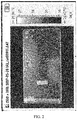
- heat is generally transferred to a battery area by using a graphite sheet or by using a holder material of a higher heat conductivity coefficient, so as to reduce a temperature of an orthogonal projection area of the circuit board of the mobile terminal with respect to the holder. It can be obtained according to FIG. 2 and FIG. 3 that the heat dissipation design reduces a temperature of an area, corresponding to the circuit board, of the mobile terminal, but because of high heat conductivity of the holder, the heat can be more rapidly transferred to the side frame of the mobile terminal; as a result, a large quantity of heat sources are concentrated on the side frame of the mobile terminal (as can be seen in FIG. 2 , a color of this area is relatively bright, which shows that the temperature of this area is relatively high).
- Embodiments of the present invention provide a holder, so as to reduce heat at a side frame of a mobile terminal.
- a holder located in a mobile terminal, where the holder includes a heat conduction area and a heat insulation area, the heat insulation area is close to an edge of the holder, the heat insulation area is adjacent to the heat conduction area, and a heat emitting element in the mobile terminal is proximate to the heat conduction area.
- the mobile terminal includes a side frame, the side frame surrounds the holder, and the heat insulation area isolates the heat emitting element from the side frame.
- the heat insulation area is provided with a heat insulation cavity, and the heat insulation cavity is vacuum or is filled with air.
- the heat insulation area is provided with a heat insulation cavity, the heat insulation cavity has a low heat conduction material, and the low heat conduction material has a heat conductivity coefficient range of 0-0.026 W/m-K.
- the heat insulation cavity is at least one strip-shaped hole or at least one elliptical hole.
- the heat insulation cavity includes at least one groove, and the groove is provided at an edge of the heat insulation area.
- an area of the heat insulation cavity occupies at least 50% of an area of the heat insulation area.
- the heat insulation area is made from a low heat conduction material, and the low heat conduction material has a heat conductivity coefficient range of 0-0.026 W/m-K.
- a material of the holder is a heat conduction material.
- the holder is a display screen holder.
- a mobile terminal including: a side frame, a heat emitting element, and the holder, where the side frame surrounds the holder.
- the heat insulation area is provided on the holder, and the heat insulation area is located at the edge of the holder and is adjacent to the heat conduction area, so that, in a process of transferring heat in the heat conduction area to the side frame, the heat is impeded by the heat insulation area, thereby reducing heat at the side frame.
- a first embodiment of the present invention provides a mobile terminal 100.
- the mobile terminal 100 includes a side frame 2, a heat emitting element 3, and a holder 1.
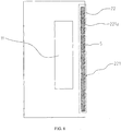
- the holder 1 is located in the mobile terminal 100, the holder 1 includes a heat conduction area 11 and a heat insulation area 12, the heat insulation area 12 is close to an edge of the holder 1, the heat insulation area 12 is adjacent to the heat conduction area 11, the heat emitting element 3 in the mobile terminal is proximate to the heat conduction area 11, and the side frame 2 surrounds the holder 1.
- the heat insulation area 12 is provided on the holder 1, and the heat insulation area 12 is close to the edge of the holder 1 and is adjacent to the heat conduction area 11, so that, in a process of transferring heat in the heat conduction area 11 to the side frame 2, the heat is impeded by the heat insulation area 12, thereby reducing heat at the side frame 2.
- the heat insulation area 12 may be located between the side frame 2 and the heat conduction area 11.
- the mobile terminal 100 is a smartphone. Certainly, in another embodiment, the mobile terminal 100 may also be a tablet computer.
- the side frame 2 includes a pair of long edges L and a pair of short edges D.
- the heat emitting element 3 is integrated on a circuit board.
- the mobile terminal may include a shielding can, and the shielding can surrounds the heat emitting element 3 on the circuit board, to prevent an electromagnetic field generated by the heat emitting element 3 from diffusing out, and prevent the electromagnetic field from being affected by an outside electromagnetic field.
- stainless steel having a thickness of 0.2 mm and copper-nickel-zinc alloy having a thickness of 0.2 mm may be used as materials of the shielding can.
- the heat conduction medium may be heat conduction silica gel.
- the mobile terminal may not have a shielding can.
- the holder 1 may play a role of a shielding can, that is, prevent the electromagnetic field generated by the heat emitting element 3 from diffusing out, and prevent the electromagnetic field from being affected by an outside electromagnetic field.
- the heat emitting element 3 is close to a right long edge L1 at a right side of the side frame 2, the heat conduction area 11 is generally provided close to the right long edge L1.
- the heat conduction area 11 is relatively near the right long edge L1; therefore, heat is much concentrated at the right long edge L1.
- the heat insulation area 12 is provided close to the right long edge L1.
- the heat insulation area 12 may also be provided between the heat conduction area 11 and the short edge D according to an actual need, or provided between the heat conduction area 11 and the other long edge L; or the heat insulation area 12 may be separately disposed between the heat conduction area 11 and the long edge L and between the heat conduction area 11 and the short edge D.
- the mobile terminal includes the side frame 2, the side frame 2 surrounds the holder 1, and the heat insulation area 12 may completely isolate the heat emitting element 3 from the side frame 2.
- the heat insulation area 12 completely isolates the heat emitting element 3 from the side frame 2, so that when the heat generated by the heat emitting element 3 is transferred to the side frame 2, the heat can pass through the heat insulation area 12, so as to impede all the heat, to improve a heat insulation effect of the heat insulation area 12.
- two ends, oppositely provided along a direction of the long edge L, of the heat insulation area 12 respectively exceed two ends, oppositely provided along the direction of the long edge L, of the heat conduction area 11.
- a size of the heat insulation area along the direction of the long edge L is greater than a size of the heat conduction area 11 along the direction of the long edge L; therefore, when the heat emitting element 3 emits heat and the heat is transferred to the heat conduction area 11, and when the heat in the heat conduction area 11 is transferred to the side frame, the heat passes through the heat insulation area 12, so that the heat insulation area 12 can prevent the heat in the heat conduction area 11.
- the mobile terminal 100 may further perform analysis according to main heat distribution in the heat conduction area 11, and then correspondingly set a size of the heat insulation area 12. That is, a length of the heat insulation area 12 along a length extending direction of the holder 1 is not necessarily greater than a length of the heat conduction area 11 along the holder 1, and may be less than or equal to the length of the heat conduction area 11 along the holder 1, as long as heat reception at a side of the mobile terminal 100 can satisfy an actually needed situation.
- the heat insulation area 12 is provided with a heat insulation cavity 121, and the heat insulation cavity 121 is vacuum or is filled with air 5.
- a heat conductivity coefficient of the air 5 is approximately 0.026 W/m-K in a closed small gap and is far less than that of another material.
- a heat conductivity coefficient of plastic is greater than 0.2 W/m-K
- a heat conductivity coefficient of metal is within 10-400 W/m-K
- a heat conductivity coefficient of glass is approximately 2 W/m-K.
- the materials listed above are generally used to manufacture the holder 1.
- a medium with a relatively small heat conductivity coefficient is introduced to a material with a relatively large heat conductivity coefficient, so that heat resistance is formed at a location at which the medium with the relatively small heat conductivity coefficient is introduced in the holder 1, so as to form the heat insulation area 12.
- heat insulation cavity 121 is filled with the air 5.
- the air 5 exists in the mobile terminal 100.
- the heat insulation cavity 121 may also form heat resistance in another manner.
- the heat insulation cavity 121 is configured to accommodate a low heat conduction material, and the low heat conduction material has a heat conductivity coefficient range of 0-0.026 W/m-K.
- the heat insulation area 12 may be made from a low heat conduction material, and the low heat conduction material has a heat conductivity coefficient range of 0-0.026 W/m-K.
- the heat insulation area 12 is made from a material having a heat conductivity coefficient range of 0-0.26 W/m-K, and a heat conductivity coefficient of a material whose heat conductivity coefficient is within the heat conductivity coefficient range is far less than that of another material.
- metal has a heat conductivity coefficient of 10-400 W/m-K
- glass has a heat conductivity coefficient of approximately 2 W/m-K.
- the materials listed above are generally used to manufacture the holder 1.
- a medium with a relatively small heat conductivity coefficient is introduced to a material with a relatively large heat conductivity coefficient, so that heat resistance is formed at a location at which the medium with the relatively small heat conductivity coefficient is introduced in the holder 1, so as to form the heat insulation area 12.
- the heat insulation cavity 121 is at least one strip-shaped hole or at least one elliptical hole.
- the heat insulation area 12 is provided with the hole-shaped heat insulation cavity 121, so that processing on the holder 1 is relatively simple.
- the heat insulation cavity 121 is at least one strip-shaped hole.
- the heat insulation cavity 121 may also be at least one elliptical hole or a hole of another shape.
- the heat emitting element 3 may be a heating chip and there are three heat insulation cavities 121, which are strip-shaped holes.
- the holes have a length of 5 mm and have a width of 1 mm, and a gap between the holes is greater than 1 mm and less than 2 mm.
- an area of the heat insulation cavity 121 occupies at least 50% of an area of the heat insulation area 12.
- the heat insulation cavity 121 is vacuum or is filled with the air 5, so that a heat-conducting property of the heat insulation cavity 121 becomes poorer, and heat resistance is formed. Therefore, a larger area of the heat insulation cavity 121 indicates a better heat insulation effect of the heat insulation area 12.
- each of the strip-shaped holes has a dimension of 5 mm along the direction of the long edge L (that is, each of the strip-shaped holes has a length of 5 mm along the direction of the long edge L).
- the strip-shaped hole has a dimension of 1 mm along a direction perpendicular to the long edge L (that is, each of the strip-shaped holes has a length of 1 mm along a direction of the short edge).
- a spacing between two neighboring strip-shaped holes is 2 mm.
- the area of the heat insulation cavity 121 occupies approximately 50% of the area of the heat insulation area 12.
- the heat insulation cavity 121 may also be one strip-shaped hole. That is, the area of the heat insulation cavity 121 occupies 100% of the area of the heat insulation area 12, thereby achieving a better heat insulation effect.
- a heat insulation cavity 221 includes at least one groove 221a, where the groove 221a is provided at an edge of a heat insulation area 22.
- An inward dentiform structure is formed at an edge of the heat insulation area 22 because of existence of the groove 221a.
- the heat insulation cavity 221 may include seven grooves 221a.
- Each of the groove 221a has a dimension of 5 mm along the direction of the long edge L (that is, each of the grooves 221a has a length of 5 mm along the direction of the long edge L).
- the groove 221a has a dimension of 1.5 mm along a direction perpendicular to the long edge L (that is, the groove has a length of 1.5 mm along the direction of the short edge).
- a spacing between two neighboring grooves 221a is 2 mm.
- An area of the heat insulation cavity 221 occupies approximately 50% of an area of the heat insulation area 22.
- the heat insulation cavity 221 may also include one groove 221a. That is, the area of the heat insulation cavity 221 occupies 100% of the area of the heat insulation area 22, thereby achieving a better heat insulation effect.
- the heat insulation cavity 221 may also be provided on a same holder 1 in a hole shape and in a form of the groove 221a according to an actual need.
- the material of the holder 1 is a heat conduction material. Heat in the heat emitting element 3 is rapidly transferred to the holder 1 by means of heat conductivity of the holder 1, and then the heat is transferred to the outside of the mobile terminal 100, so that heat dissipation processing on the mobile terminal 100 is more effective.
- the material of the holder 1 may be graphite. When the holder 1 is located between a display screen and the circuit board, heat in the circuit board can be more rapidly transferred to the holder 1.
- the heat in the holder 1 can be more rapidly transferred to the outside of the mobile terminal 100 because of high heat conductivity of the holder 1, so that the heat dissipation processing on the mobile terminal 100 is more effective.
- the material of the holder 1 may also be another material according to an actual need of the mobile terminal 100. For example, if the mobile terminal 100 does not have a relatively high requirement on heat dissipation performance, the material of the holder 1 may also be a material with a relatively low heat-conducting property.
- the heat emitting element 3 When the mobile terminal 100 starts to be equipped, the heat emitting element 3 first needs to be proximate to the heat conduction area 11, and the shielding can and the heat conduction medium are disposed between the heat emitting element 3 and the heat conduction area 11, so as to implement a shielding effect and a heat conduction effect.
- the heat emitting element 3 starts to generate heat, the heat is transferred from the heat emitting element 3 to the holder 1 because of the heat conductivity of the holder 1, and subsequently the holder 1 transfers the heat to the side frame 2 of the mobile terminal 100.
- the holder 1 is a display screen holder.
- the heat insulation area 12 is provided on the holder 1, and the heat insulation area 12 is close to the edge of the holder 1 and is adjacent to the heat conduction area 11, so that, in a process of transferring heat in the heat conduction area 11 to the side frame 2, the heat is impeded by the heat insulation area 12, thereby reducing heat at the side frame 2.
- the heat insulation area 12 completely isolates the heat emitting element 3 from the side frame 2, so that the heat insulation effect of the heat insulation area 12 is improved.
- the heat insulation area 12 is provided with the heat insulation cavity 121, where the heat insulation cavity 121 is vacuum or is filled with the air 5, so that heat insulation is relatively easy to be implemented in the heat insulation area 12.
- the heat insulation area 12 is made from a low heat conduction material, and the low heat conduction material has a thermal insulation coefficient range of 0-0.026 W/m-K, so that the heat insulation effect of the heat insulation area 12 is better.
- the heat insulation cavity 121 is at least one strip-shaped hole or at least one elliptical hole, so that processing on the holder 1 is relatively simple.
- the heat insulation cavity 121 includes at least one groove 221, and the groove 221 is provided at an edge of the heat insulation area 12, so that there are various providing manners for the heat insulation cavity 121.
- the area of the heat insulation cavity 121 occupies at least 50% of the area of the heat insulation area 12, so that the heat insulation effect of the heat insulation area 12 is better.
- the material of the holder 1 is a heat conduction material, so that the heat dissipation processing on the mobile terminal 100 is more effective.
- Embodiment 1 A holder, located in a mobile terminal, wherein the holder comprises a heat conduction area and a heat insulation area, the heat insulation area is close to an edge of the holder, the heat insulation area is adjacent to the heat conduction area, and a heat emitting element in the mobile terminal is proximate to the heat conduction area.
- Embodiment 2 The holder according to embodiment 1, wherein the mobile terminal comprises a side frame, the side frame surrounds the holder, and the heat insulation area isolates the heat emitting element from the side frame.
- Embodiment 3 The holder according to embodiment 1, wherein the heat insulation area is provided with a heat insulation cavity, and the heat insulation cavity is vacuum or is filled with air.
- Embodiment 4 The holder according to embodiment 1, wherein the heat insulation area is provided with a heat insulation cavity, the heat insulation cavity has a low heat conduction material, and the low heat conduction material has a heat conductivity coefficient range of 0-0.026 W/m-K.
- Embodiment 5 The holder according to embodiment 3 or 4, wherein the heat insulation cavity is at least one strip-shaped hole or at least one elliptical hole.
- Embodiment 6 The holder according to embodiment 3 or 4, wherein the heat insulation cavity comprises at least one groove, and the groove is provided at an edge of the heat insulation area.
- Embodiment 7 The holder according to embodiment 3 or 4, wherein an area of the heat insulation cavity occupies at least 50% of an area of the heat insulation area.
- Embodiment 8 The holder according to embodiment 1, wherein the heat insulation area is made from a low heat conduction material, and the low heat conduction material has a heat conductivity coefficient range of 0-0.026 W/m-K.
- Embodiment 9 The holder according to embodiment 1, wherein a material of the holder is a heat conduction material.
- Embodiment 10 The holder according to any one of embodiments 1 to 9, wherein the holder is a display screen holder.
- Embodiment 11 A mobile terminal, comprising: a side frame, a heat emitting element, and the holder according to any one of embodiments 1 to 10, wherein the side frame surrounds the holder.
Landscapes
- Engineering & Computer Science (AREA)
- Theoretical Computer Science (AREA)
- Physics & Mathematics (AREA)
- Computer Hardware Design (AREA)
- Human Computer Interaction (AREA)
- General Engineering & Computer Science (AREA)
- General Physics & Mathematics (AREA)
- Microelectronics & Electronic Packaging (AREA)
- Thermal Sciences (AREA)
- Telephone Set Structure (AREA)
- Cooling Or The Like Of Electrical Apparatus (AREA)
Priority Applications (1)
| Application Number | Priority Date | Filing Date | Title |
|---|---|---|---|
| EP18182424.4A EP3461248B1 (de) | 2014-03-21 | 2014-03-21 | Mobiles endgerät |
Applications Claiming Priority (3)
| Application Number | Priority Date | Filing Date | Title |
|---|---|---|---|
| PCT/CN2014/073815 WO2015139285A1 (zh) | 2014-03-21 | 2014-03-21 | 支架和移动终端 |
| EP14886101.6A EP3107362B1 (de) | 2014-03-21 | 2014-03-21 | Rahmen und mobiles endgerät |
| EP18182424.4A EP3461248B1 (de) | 2014-03-21 | 2014-03-21 | Mobiles endgerät |
Related Parent Applications (2)
| Application Number | Title | Priority Date | Filing Date |
|---|---|---|---|
| EP14886101.6A Division EP3107362B1 (de) | 2014-03-21 | 2014-03-21 | Rahmen und mobiles endgerät |
| EP14886101.6A Division-Into EP3107362B1 (de) | 2014-03-21 | 2014-03-21 | Rahmen und mobiles endgerät |
Publications (2)
| Publication Number | Publication Date |
|---|---|
| EP3461248A1 true EP3461248A1 (de) | 2019-03-27 |
| EP3461248B1 EP3461248B1 (de) | 2022-07-06 |
Family
ID=54143701
Family Applications (2)
| Application Number | Title | Priority Date | Filing Date |
|---|---|---|---|
| EP18182424.4A Active EP3461248B1 (de) | 2014-03-21 | 2014-03-21 | Mobiles endgerät |
| EP14886101.6A Active EP3107362B1 (de) | 2014-03-21 | 2014-03-21 | Rahmen und mobiles endgerät |
Family Applications After (1)
| Application Number | Title | Priority Date | Filing Date |
|---|---|---|---|
| EP14886101.6A Active EP3107362B1 (de) | 2014-03-21 | 2014-03-21 | Rahmen und mobiles endgerät |
Country Status (6)
| Country | Link |
|---|---|
| US (2) | US9910468B2 (de) |
| EP (2) | EP3461248B1 (de) |
| JP (1) | JP6397045B2 (de) |
| KR (2) | KR102089472B1 (de) |
| CN (2) | CN105611984B (de) |
| WO (1) | WO2015139285A1 (de) |
Families Citing this family (7)
| Publication number | Priority date | Publication date | Assignee | Title |
|---|---|---|---|---|
| KR102483238B1 (ko) * | 2016-08-01 | 2022-12-30 | 삼성전자 주식회사 | 방열 장치 및 이를 구비하는 전자 장치 |
| KR102709687B1 (ko) | 2017-01-06 | 2024-09-26 | 삼성전자주식회사 | 방열 구조 및 그를 포함하는 전자 장치 |
| CN106879226A (zh) * | 2017-01-20 | 2017-06-20 | 努比亚技术有限公司 | 一种控制壳体温度的装置和电子设备 |
| EP3579673B1 (de) * | 2017-03-02 | 2022-01-26 | Huawei Technologies Co., Ltd. | Wärmeleitende komponente und mobiles endgerät |
| CN107592763A (zh) * | 2017-09-29 | 2018-01-16 | 深圳传音制造有限公司 | 一种隔热结构、移动终端以及隔热方法 |
| CN110691156A (zh) * | 2019-11-06 | 2020-01-14 | 北京字节跳动网络技术有限公司 | 用于电子设备的支撑件和电子设备 |
| EP4738050A1 (de) * | 2023-08-02 | 2026-05-06 | Samsung Electronics Co., Ltd. | Wearable-vorrichtung mit isolierungsstruktur |
Citations (4)
| Publication number | Priority date | Publication date | Assignee | Title |
|---|---|---|---|---|
| EP1233666A1 (de) * | 2000-06-06 | 2002-08-21 | Mitsubishi Denki Kabushiki Kaisha | Kühlstruktur einer kommunikationseinrichtung |
| CN201115242Y (zh) * | 2007-09-20 | 2008-09-10 | 深圳华为通信技术有限公司 | 基于用户满意度的电子产品散热装置 |
| US20130301221A1 (en) * | 2013-03-07 | 2013-11-14 | Jones Tech Plc. | Thermal management system and method between heat generating chip and housing in electronic apparatus |
| WO2013191493A1 (en) * | 2012-06-20 | 2013-12-27 | Lg Electronics Inc. | Terminal unit |
Family Cites Families (55)
| Publication number | Priority date | Publication date | Assignee | Title |
|---|---|---|---|---|
| JP2997273B2 (ja) | 1989-05-29 | 2000-01-11 | 西部電機株式会社 | ステージ可動支持装置 |
| JPH0498030U (de) * | 1991-01-12 | 1992-08-25 | ||
| US5581443A (en) | 1994-09-14 | 1996-12-03 | Kabushiki Kaisha Toshiba | Structure for cooling a circuit module having a circuit board and a heat-generating IC chip mounted on the board, and portable electronic apparatus incorporating the structure |
| JP3876491B2 (ja) * | 1997-02-27 | 2007-01-31 | 三菱電機株式会社 | 真空断熱パネル及びその製造方法並びにそれを用いた冷蔵庫 |
| JPH11143584A (ja) * | 1997-11-07 | 1999-05-28 | Pfu Ltd | 携帯端末装置の放熱構造 |
| JP3601282B2 (ja) | 1998-01-20 | 2004-12-15 | 株式会社日立製作所 | ノート形コンピュータ |
| JP3366244B2 (ja) * | 1998-02-04 | 2003-01-14 | 富士通株式会社 | 電子機器 |
| US6414844B1 (en) | 1999-09-03 | 2002-07-02 | Matsushita Electric Industrial Co., Ltd. | Portable information processing apparatus |
| JP3656822B2 (ja) * | 1999-09-03 | 2005-06-08 | 松下電器産業株式会社 | 携帯型情報処理装置 |
| TW470837B (en) * | 2000-04-21 | 2002-01-01 | Matsushita Refrigeration | Vacuum heat insulator |
| JP2001308137A (ja) | 2000-04-26 | 2001-11-02 | Matsushita Electric Works Ltd | 半導体装置及びその製造方法 |
| DE60137843D1 (de) * | 2000-06-06 | 2009-04-16 | Panasonic Corp | Tragbares informationsgerät |
| JP2003188323A (ja) * | 2001-12-19 | 2003-07-04 | Sony Corp | グラファイトシート及びその製造方法 |
| US20030161132A1 (en) | 2002-02-05 | 2003-08-28 | Mitsubishi Denki Kabushiki Kaisha | Communication device |
| JP3559035B2 (ja) * | 2002-12-05 | 2004-08-25 | 松下冷機株式会社 | 真空断熱材およびその製造方法、並びに真空断熱材を使用した防寒具およびパーソナルコンピューター |
| US7188484B2 (en) | 2003-06-09 | 2007-03-13 | Lg Electronics Inc. | Heat dissipating structure for mobile device |
| US7292441B2 (en) * | 2003-11-25 | 2007-11-06 | Advanced Energy Technology Inc. | Thermal solution for portable electronic devices |
| JP2005277163A (ja) * | 2004-03-25 | 2005-10-06 | Kyocera Corp | 配線基板 |
| JP2006165154A (ja) * | 2004-12-06 | 2006-06-22 | Matsushita Electric Ind Co Ltd | 熱伝導部材 |
| KR100865199B1 (ko) * | 2004-12-07 | 2008-10-23 | 파나소닉 주식회사 | 진공 단열재, 진공 단열재의 제조 방법 및 진공 단열재를이용한 단열 박스 |
| JP4487799B2 (ja) * | 2005-02-25 | 2010-06-23 | 株式会社日立製作所 | 恒温輸送容器 |
| CA2877959C (en) * | 2006-08-22 | 2017-06-13 | Charles F. Barry | Apparatus and method for thermal stabilization of pcb-mounted electronic components within an enclosed housing |
| JP5179746B2 (ja) | 2006-11-22 | 2013-04-10 | 京セラ株式会社 | 携帯端末装置 |
| US7486517B2 (en) * | 2006-12-20 | 2009-02-03 | Nokia Corporation | Hand-held portable electronic device having a heat spreader |
| CN201114231Y (zh) | 2007-07-02 | 2008-09-10 | 华为技术有限公司 | 一种防止用户敏感面温升的移动终端 |
| EP2075993A4 (de) * | 2007-07-02 | 2009-12-02 | Huawei Tech Co Ltd | Mobiles endgerät, das die temperaturerhöhung einer fläche, fühlbar für einen benutzer, vermeidet |
| CN201278544Y (zh) * | 2008-09-12 | 2009-07-22 | 中兴通讯股份有限公司 | 无线通讯终端模块 |
| KR101179364B1 (ko) | 2008-09-22 | 2012-09-03 | 파나소닉 주식회사 | 휴대전자기기 |
| JP2010165728A (ja) * | 2009-01-13 | 2010-07-29 | Kyocera Corp | 多層基板及び携帯通信機器 |
| JP2010251386A (ja) * | 2009-04-10 | 2010-11-04 | Nec Corp | 熱拡散部材を備える電子機器、熱拡散部材を備える電子機器の製法及び熱拡散部材 |
| JP5327024B2 (ja) * | 2009-12-03 | 2013-10-30 | 三菱エンジニアリングプラスチックス株式会社 | 放熱部付き二色成形品及び発熱体付き機器 |
| CN201550395U (zh) * | 2009-12-10 | 2010-08-11 | 华为终端有限公司 | 无线终端和壳体 |
| US8391010B2 (en) * | 2010-08-19 | 2013-03-05 | Apple Inc. | Internal frame optimized for stiffness and heat transfer |
| JP2011042575A (ja) | 2010-11-22 | 2011-03-03 | Nichias Corp | 無機繊維質成形体及びその製造方法 |
| US8537553B2 (en) | 2011-02-14 | 2013-09-17 | Futurewei Technologies, Inc. | Devices having anisotropic conductivity heatsinks, and methods of making thereof |
| CN202003615U (zh) * | 2011-03-14 | 2011-10-05 | 华为终端有限公司 | 一种显示屏散热装置 |
| EP2661164A4 (de) * | 2011-06-14 | 2015-03-25 | Huawei Device Co Ltd | Vorrichtung mit wärmedämmungsstruktur |
| JPWO2013018553A1 (ja) | 2011-07-29 | 2015-03-05 | 日本電気株式会社 | 携帯型電子機器 |
| CN102427159A (zh) * | 2011-08-12 | 2012-04-25 | 华为终端有限公司 | 无线终端及其天线架 |
| JP5067497B2 (ja) * | 2011-09-28 | 2012-11-07 | 富士通株式会社 | 表示装置、ディスプレイパネルユニット、および情報処理装置 |
| CN202335181U (zh) | 2011-10-11 | 2012-07-11 | 捷开通讯科技(上海)有限公司 | 电子装置的散热结构及电子装置 |
| DE102011117490A1 (de) * | 2011-10-27 | 2013-05-02 | Asia Vital Components Co., Ltd. | Vapor-Chamber-Kühler und Verfahren zu dessen Herstellung |
| US20140355194A1 (en) | 2012-01-16 | 2014-12-04 | Nec Casio Mobile Communications, Ltd. | Portable terminal device |
| US20150005043A1 (en) * | 2012-01-16 | 2015-01-01 | Nec Casio Modile Communications, Ltd. | Portable terminal device |
| JP2013150067A (ja) | 2012-01-17 | 2013-08-01 | Kyocera Corp | 携帯端末カバー |
| JP2013214868A (ja) * | 2012-04-02 | 2013-10-17 | Sharp Corp | 携帯情報端末 |
| CN102711416B (zh) | 2012-05-24 | 2015-10-21 | 中兴通讯股份有限公司 | 散热处理装置及移动终端 |
| CN203086894U (zh) | 2012-12-31 | 2013-07-24 | 青岛海信移动通信技术股份有限公司 | 隔热金属机壳及便携式移动终端 |
| CN103209574B (zh) | 2013-04-24 | 2017-04-12 | 惠州Tcl移动通信有限公司 | 一种移动终端的散热装置、方法及移动终端 |
| CN203327471U (zh) | 2013-07-23 | 2013-12-04 | 奇鋐科技股份有限公司 | 散热结构及具有该散热结构的手持式电子装置 |
| KR101675868B1 (ko) * | 2013-10-31 | 2016-11-15 | 주식회사 아모그린텍 | 방열 부재 및 그를 구비한 휴대용 단말기 |
| US9578791B1 (en) * | 2015-08-17 | 2017-02-21 | Asia Vital Components Co., Ltd. | Internal frame structure with heat isolation effect and electronic apparatus with the internal frame structure |
| US10019046B2 (en) * | 2015-08-17 | 2018-07-10 | Asia Vital Components Co., Ltd. | Internal frame structure with heat insulation effect and electronic apparatus with the internal frame structure |
| US9690341B2 (en) * | 2015-09-04 | 2017-06-27 | Asia Vital Components Co., Ltd. | Heat insulation structure for hand-held device and hand-held device with same |
| KR102483238B1 (ko) * | 2016-08-01 | 2022-12-30 | 삼성전자 주식회사 | 방열 장치 및 이를 구비하는 전자 장치 |
-
2014
- 2014-03-21 KR KR1020167027927A patent/KR102089472B1/ko active Active
- 2014-03-21 EP EP18182424.4A patent/EP3461248B1/de active Active
- 2014-03-21 KR KR1020187025285A patent/KR101953333B1/ko active Active
- 2014-03-21 JP JP2016557014A patent/JP6397045B2/ja active Active
- 2014-03-21 CN CN201480005568.0A patent/CN105611984B/zh active Active
- 2014-03-21 CN CN201810011916.5A patent/CN108055815B/zh active Active
- 2014-03-21 WO PCT/CN2014/073815 patent/WO2015139285A1/zh not_active Ceased
- 2014-03-21 US US15/127,705 patent/US9910468B2/en active Active
- 2014-03-21 EP EP14886101.6A patent/EP3107362B1/de active Active
-
2018
- 2018-01-23 US US15/878,017 patent/US10481654B2/en active Active
Patent Citations (4)
| Publication number | Priority date | Publication date | Assignee | Title |
|---|---|---|---|---|
| EP1233666A1 (de) * | 2000-06-06 | 2002-08-21 | Mitsubishi Denki Kabushiki Kaisha | Kühlstruktur einer kommunikationseinrichtung |
| CN201115242Y (zh) * | 2007-09-20 | 2008-09-10 | 深圳华为通信技术有限公司 | 基于用户满意度的电子产品散热装置 |
| WO2013191493A1 (en) * | 2012-06-20 | 2013-12-27 | Lg Electronics Inc. | Terminal unit |
| US20130301221A1 (en) * | 2013-03-07 | 2013-11-14 | Jones Tech Plc. | Thermal management system and method between heat generating chip and housing in electronic apparatus |
Also Published As
| Publication number | Publication date |
|---|---|
| CN105611984B (zh) | 2018-01-16 |
| CN105611984A (zh) | 2016-05-25 |
| EP3107362A4 (de) | 2016-12-28 |
| EP3107362A1 (de) | 2016-12-21 |
| CN108055815B (zh) | 2020-04-21 |
| KR101953333B1 (ko) | 2019-02-28 |
| KR102089472B1 (ko) | 2020-03-16 |
| WO2015139285A1 (zh) | 2015-09-24 |
| JP2017511643A (ja) | 2017-04-20 |
| CN108055815A (zh) | 2018-05-18 |
| EP3461248B1 (de) | 2022-07-06 |
| US9910468B2 (en) | 2018-03-06 |
| KR20180100274A (ko) | 2018-09-07 |
| US10481654B2 (en) | 2019-11-19 |
| US20180150115A1 (en) | 2018-05-31 |
| EP3107362B1 (de) | 2018-09-19 |
| KR20160130845A (ko) | 2016-11-14 |
| JP6397045B2 (ja) | 2018-09-26 |
| US20170139452A1 (en) | 2017-05-18 |
Similar Documents
| Publication | Publication Date | Title |
|---|---|---|
| US10481654B2 (en) | Holder and mobile terminal | |
| US9054432B2 (en) | Terminal plate set and electric connector including the same | |
| US9244505B2 (en) | Portable electronic device with exposed heat dissipating mechanism | |
| CN104619146A (zh) | 一种散热装置及电子设备 | |
| CN203645968U (zh) | 光模块散热装置 | |
| EP3163987A1 (de) | Rauschunterdrückungsvorrichtung und -verfahren | |
| TW201508453A (zh) | 散熱器 | |
| JP6591013B2 (ja) | モバイル端末 | |
| CN205305289U (zh) | 上架型全密闭式编解码器 | |
| JP2011066039A (ja) | 無線通信装置 | |
| CN205052045U (zh) | 一种车载产品的散热系统 | |
| CN203015353U (zh) | 无线音视频通信装置 | |
| CN107864600B (zh) | 一种用于台式设备的散热装置及台式设备 | |
| TW201138605A (en) | Enclosure | |
| US20170042018A1 (en) | Dual Layer Shielding Cover and Terminal | |
| CN206024410U (zh) | 电磁屏蔽罩及电子设备 | |
| CN205305288U (zh) | 密闭超薄盒式编解码器 | |
| CN206100156U (zh) | 一种高效散热手机壳 | |
| CN103593027A (zh) | 一种笔记本散热器 | |
| CN210808099U (zh) | 一种屏蔽罩装置 | |
| CN206136563U (zh) | 可携带电子装置的真空散热结构 | |
| CN203708734U (zh) | 放电仪散热结构 | |
| CN107734947A (zh) | 电磁屏蔽罩及电子设备 | |
| CN102243515A (zh) | 机箱 | |
| TW201146126A (en) | Enclosure |
Legal Events
| Date | Code | Title | Description |
|---|---|---|---|
| PUAI | Public reference made under article 153(3) epc to a published international application that has entered the european phase |
Free format text: ORIGINAL CODE: 0009012 |
|
| STAA | Information on the status of an ep patent application or granted ep patent |
Free format text: STATUS: THE APPLICATION HAS BEEN PUBLISHED |
|
| AC | Divisional application: reference to earlier application |
Ref document number: 3107362 Country of ref document: EP Kind code of ref document: P |
|
| AK | Designated contracting states |
Kind code of ref document: A1 Designated state(s): AL AT BE BG CH CY CZ DE DK EE ES FI FR GB GR HR HU IE IS IT LI LT LU LV MC MK MT NL NO PL PT RO RS SE SI SK SM TR |
|
| RAP1 | Party data changed (applicant data changed or rights of an application transferred) |
Owner name: HUAWEI DEVICE CO., LTD. |
|
| STAA | Information on the status of an ep patent application or granted ep patent |
Free format text: STATUS: REQUEST FOR EXAMINATION WAS MADE |
|
| 17P | Request for examination filed |
Effective date: 20190927 |
|
| RBV | Designated contracting states (corrected) |
Designated state(s): AL AT BE BG CH CY CZ DE DK EE ES FI FR GB GR HR HU IE IS IT LI LT LU LV MC MK MT NL NO PL PT RO RS SE SI SK SM TR |
|
| STAA | Information on the status of an ep patent application or granted ep patent |
Free format text: STATUS: EXAMINATION IS IN PROGRESS |
|
| 17Q | First examination report despatched |
Effective date: 20201109 |
|
| GRAP | Despatch of communication of intention to grant a patent |
Free format text: ORIGINAL CODE: EPIDOSNIGR1 |
|
| STAA | Information on the status of an ep patent application or granted ep patent |
Free format text: STATUS: GRANT OF PATENT IS INTENDED |
|
| INTG | Intention to grant announced |
Effective date: 20220118 |
|
| GRAS | Grant fee paid |
Free format text: ORIGINAL CODE: EPIDOSNIGR3 |
|
| GRAA | (expected) grant |
Free format text: ORIGINAL CODE: 0009210 |
|
| STAA | Information on the status of an ep patent application or granted ep patent |
Free format text: STATUS: THE PATENT HAS BEEN GRANTED |
|
| AC | Divisional application: reference to earlier application |
Ref document number: 3107362 Country of ref document: EP Kind code of ref document: P |
|
| AK | Designated contracting states |
Kind code of ref document: B1 Designated state(s): AL AT BE BG CH CY CZ DE DK EE ES FI FR GB GR HR HU IE IS IT LI LT LU LV MC MK MT NL NO PL PT RO RS SE SI SK SM TR |
|
| REG | Reference to a national code |
Ref country code: AT Ref legal event code: REF Ref document number: 1503808 Country of ref document: AT Kind code of ref document: T Effective date: 20220715 Ref country code: CH Ref legal event code: EP |
|
| REG | Reference to a national code |
Ref country code: DE Ref legal event code: R096 Ref document number: 602014084259 Country of ref document: DE |
|
| REG | Reference to a national code |
Ref country code: IE Ref legal event code: FG4D |
|
| REG | Reference to a national code |
Ref country code: NL Ref legal event code: FP |
|
| REG | Reference to a national code |
Ref country code: LT Ref legal event code: MG9D |
|
| PG25 | Lapsed in a contracting state [announced via postgrant information from national office to epo] |
Ref country code: SE Free format text: LAPSE BECAUSE OF FAILURE TO SUBMIT A TRANSLATION OF THE DESCRIPTION OR TO PAY THE FEE WITHIN THE PRESCRIBED TIME-LIMIT Effective date: 20220706 Ref country code: RS Free format text: LAPSE BECAUSE OF FAILURE TO SUBMIT A TRANSLATION OF THE DESCRIPTION OR TO PAY THE FEE WITHIN THE PRESCRIBED TIME-LIMIT Effective date: 20220706 Ref country code: PT Free format text: LAPSE BECAUSE OF FAILURE TO SUBMIT A TRANSLATION OF THE DESCRIPTION OR TO PAY THE FEE WITHIN THE PRESCRIBED TIME-LIMIT Effective date: 20221107 Ref country code: NO Free format text: LAPSE BECAUSE OF FAILURE TO SUBMIT A TRANSLATION OF THE DESCRIPTION OR TO PAY THE FEE WITHIN THE PRESCRIBED TIME-LIMIT Effective date: 20221006 Ref country code: LV Free format text: LAPSE BECAUSE OF FAILURE TO SUBMIT A TRANSLATION OF THE DESCRIPTION OR TO PAY THE FEE WITHIN THE PRESCRIBED TIME-LIMIT Effective date: 20220706 Ref country code: LT Free format text: LAPSE BECAUSE OF FAILURE TO SUBMIT A TRANSLATION OF THE DESCRIPTION OR TO PAY THE FEE WITHIN THE PRESCRIBED TIME-LIMIT Effective date: 20220706 Ref country code: FI Free format text: LAPSE BECAUSE OF FAILURE TO SUBMIT A TRANSLATION OF THE DESCRIPTION OR TO PAY THE FEE WITHIN THE PRESCRIBED TIME-LIMIT Effective date: 20220706 Ref country code: ES Free format text: LAPSE BECAUSE OF FAILURE TO SUBMIT A TRANSLATION OF THE DESCRIPTION OR TO PAY THE FEE WITHIN THE PRESCRIBED TIME-LIMIT Effective date: 20220706 |
|
| REG | Reference to a national code |
Ref country code: AT Ref legal event code: MK05 Ref document number: 1503808 Country of ref document: AT Kind code of ref document: T Effective date: 20220706 |
|
| PG25 | Lapsed in a contracting state [announced via postgrant information from national office to epo] |
Ref country code: PL Free format text: LAPSE BECAUSE OF FAILURE TO SUBMIT A TRANSLATION OF THE DESCRIPTION OR TO PAY THE FEE WITHIN THE PRESCRIBED TIME-LIMIT Effective date: 20220706 Ref country code: IS Free format text: LAPSE BECAUSE OF FAILURE TO SUBMIT A TRANSLATION OF THE DESCRIPTION OR TO PAY THE FEE WITHIN THE PRESCRIBED TIME-LIMIT Effective date: 20221106 Ref country code: GR Free format text: LAPSE BECAUSE OF FAILURE TO SUBMIT A TRANSLATION OF THE DESCRIPTION OR TO PAY THE FEE WITHIN THE PRESCRIBED TIME-LIMIT Effective date: 20221007 |
|
| REG | Reference to a national code |
Ref country code: DE Ref legal event code: R097 Ref document number: 602014084259 Country of ref document: DE |
|
| PG25 | Lapsed in a contracting state [announced via postgrant information from national office to epo] |
Ref country code: SM Free format text: LAPSE BECAUSE OF FAILURE TO SUBMIT A TRANSLATION OF THE DESCRIPTION OR TO PAY THE FEE WITHIN THE PRESCRIBED TIME-LIMIT Effective date: 20220706 Ref country code: RO Free format text: LAPSE BECAUSE OF FAILURE TO SUBMIT A TRANSLATION OF THE DESCRIPTION OR TO PAY THE FEE WITHIN THE PRESCRIBED TIME-LIMIT Effective date: 20220706 Ref country code: DK Free format text: LAPSE BECAUSE OF FAILURE TO SUBMIT A TRANSLATION OF THE DESCRIPTION OR TO PAY THE FEE WITHIN THE PRESCRIBED TIME-LIMIT Effective date: 20220706 Ref country code: CZ Free format text: LAPSE BECAUSE OF FAILURE TO SUBMIT A TRANSLATION OF THE DESCRIPTION OR TO PAY THE FEE WITHIN THE PRESCRIBED TIME-LIMIT Effective date: 20220706 Ref country code: AT Free format text: LAPSE BECAUSE OF FAILURE TO SUBMIT A TRANSLATION OF THE DESCRIPTION OR TO PAY THE FEE WITHIN THE PRESCRIBED TIME-LIMIT Effective date: 20220706 |
|
| PLBE | No opposition filed within time limit |
Free format text: ORIGINAL CODE: 0009261 |
|
| STAA | Information on the status of an ep patent application or granted ep patent |
Free format text: STATUS: NO OPPOSITION FILED WITHIN TIME LIMIT |
|
| PG25 | Lapsed in a contracting state [announced via postgrant information from national office to epo] |
Ref country code: SK Free format text: LAPSE BECAUSE OF FAILURE TO SUBMIT A TRANSLATION OF THE DESCRIPTION OR TO PAY THE FEE WITHIN THE PRESCRIBED TIME-LIMIT Effective date: 20220706 Ref country code: EE Free format text: LAPSE BECAUSE OF FAILURE TO SUBMIT A TRANSLATION OF THE DESCRIPTION OR TO PAY THE FEE WITHIN THE PRESCRIBED TIME-LIMIT Effective date: 20220706 |
|
| 26N | No opposition filed |
Effective date: 20230411 |
|
| P01 | Opt-out of the competence of the unified patent court (upc) registered |
Effective date: 20230510 |
|
| PG25 | Lapsed in a contracting state [announced via postgrant information from national office to epo] |
Ref country code: AL Free format text: LAPSE BECAUSE OF FAILURE TO SUBMIT A TRANSLATION OF THE DESCRIPTION OR TO PAY THE FEE WITHIN THE PRESCRIBED TIME-LIMIT Effective date: 20220706 |
|
| PG25 | Lapsed in a contracting state [announced via postgrant information from national office to epo] |
Ref country code: SI Free format text: LAPSE BECAUSE OF FAILURE TO SUBMIT A TRANSLATION OF THE DESCRIPTION OR TO PAY THE FEE WITHIN THE PRESCRIBED TIME-LIMIT Effective date: 20220706 |
|
| PG25 | Lapsed in a contracting state [announced via postgrant information from national office to epo] |
Ref country code: MC Free format text: LAPSE BECAUSE OF FAILURE TO SUBMIT A TRANSLATION OF THE DESCRIPTION OR TO PAY THE FEE WITHIN THE PRESCRIBED TIME-LIMIT Effective date: 20220706 |
|
| REG | Reference to a national code |
Ref country code: CH Ref legal event code: PL |
|
| REG | Reference to a national code |
Ref country code: BE Ref legal event code: MM Effective date: 20230331 |
|
| PG25 | Lapsed in a contracting state [announced via postgrant information from national office to epo] |
Ref country code: LU Free format text: LAPSE BECAUSE OF NON-PAYMENT OF DUE FEES Effective date: 20230321 |
|
| REG | Reference to a national code |
Ref country code: IE Ref legal event code: MM4A |
|
| PG25 | Lapsed in a contracting state [announced via postgrant information from national office to epo] |
Ref country code: LI Free format text: LAPSE BECAUSE OF NON-PAYMENT OF DUE FEES Effective date: 20230331 Ref country code: IT Free format text: LAPSE BECAUSE OF FAILURE TO SUBMIT A TRANSLATION OF THE DESCRIPTION OR TO PAY THE FEE WITHIN THE PRESCRIBED TIME-LIMIT Effective date: 20220706 Ref country code: IE Free format text: LAPSE BECAUSE OF NON-PAYMENT OF DUE FEES Effective date: 20230321 Ref country code: CH Free format text: LAPSE BECAUSE OF NON-PAYMENT OF DUE FEES Effective date: 20230331 |
|
| PG25 | Lapsed in a contracting state [announced via postgrant information from national office to epo] |
Ref country code: BE Free format text: LAPSE BECAUSE OF NON-PAYMENT OF DUE FEES Effective date: 20230331 |
|
| PG25 | Lapsed in a contracting state [announced via postgrant information from national office to epo] |
Ref country code: HR Free format text: LAPSE BECAUSE OF FAILURE TO SUBMIT A TRANSLATION OF THE DESCRIPTION OR TO PAY THE FEE WITHIN THE PRESCRIBED TIME-LIMIT Effective date: 20220706 |
|
| PG25 | Lapsed in a contracting state [announced via postgrant information from national office to epo] |
Ref country code: HR Free format text: LAPSE BECAUSE OF FAILURE TO SUBMIT A TRANSLATION OF THE DESCRIPTION OR TO PAY THE FEE WITHIN THE PRESCRIBED TIME-LIMIT Effective date: 20220706 |
|
| PG25 | Lapsed in a contracting state [announced via postgrant information from national office to epo] |
Ref country code: BG Free format text: LAPSE BECAUSE OF FAILURE TO SUBMIT A TRANSLATION OF THE DESCRIPTION OR TO PAY THE FEE WITHIN THE PRESCRIBED TIME-LIMIT Effective date: 20220706 |
|
| PG25 | Lapsed in a contracting state [announced via postgrant information from national office to epo] |
Ref country code: BG Free format text: LAPSE BECAUSE OF FAILURE TO SUBMIT A TRANSLATION OF THE DESCRIPTION OR TO PAY THE FEE WITHIN THE PRESCRIBED TIME-LIMIT Effective date: 20220706 |
|
| PG25 | Lapsed in a contracting state [announced via postgrant information from national office to epo] |
Ref country code: CY Free format text: LAPSE BECAUSE OF FAILURE TO SUBMIT A TRANSLATION OF THE DESCRIPTION OR TO PAY THE FEE WITHIN THE PRESCRIBED TIME-LIMIT; INVALID AB INITIO Effective date: 20140321 |
|
| PG25 | Lapsed in a contracting state [announced via postgrant information from national office to epo] |
Ref country code: HU Free format text: LAPSE BECAUSE OF FAILURE TO SUBMIT A TRANSLATION OF THE DESCRIPTION OR TO PAY THE FEE WITHIN THE PRESCRIBED TIME-LIMIT; INVALID AB INITIO Effective date: 20140321 |
|
| PG25 | Lapsed in a contracting state [announced via postgrant information from national office to epo] |
Ref country code: TR Free format text: LAPSE BECAUSE OF FAILURE TO SUBMIT A TRANSLATION OF THE DESCRIPTION OR TO PAY THE FEE WITHIN THE PRESCRIBED TIME-LIMIT Effective date: 20220706 |
|
| PGFP | Annual fee paid to national office [announced via postgrant information from national office to epo] |
Ref country code: NL Payment date: 20260213 Year of fee payment: 13 |
|
| PGFP | Annual fee paid to national office [announced via postgrant information from national office to epo] |
Ref country code: GB Payment date: 20260202 Year of fee payment: 13 |
|
| PGFP | Annual fee paid to national office [announced via postgrant information from national office to epo] |
Ref country code: DE Payment date: 20260204 Year of fee payment: 13 |
|
| PGFP | Annual fee paid to national office [announced via postgrant information from national office to epo] |
Ref country code: FR Payment date: 20260209 Year of fee payment: 13 |