EP3448592B2 - Procede de laminage d'un produit de laminage - Google Patents
Procede de laminage d'un produit de laminage Download PDFInfo
- Publication number
- EP3448592B2 EP3448592B2 EP17723941.5A EP17723941A EP3448592B2 EP 3448592 B2 EP3448592 B2 EP 3448592B2 EP 17723941 A EP17723941 A EP 17723941A EP 3448592 B2 EP3448592 B2 EP 3448592B2
- Authority
- EP
- European Patent Office
- Prior art keywords
- lubricant
- rolling
- rolled material
- contact zone
- cooling
- Prior art date
- Legal status (The legal status is an assumption and is not a legal conclusion. Google has not performed a legal analysis and makes no representation as to the accuracy of the status listed.)
- Active
Links
Images

Classifications
-
- B—PERFORMING OPERATIONS; TRANSPORTING
- B21—MECHANICAL METAL-WORKING WITHOUT ESSENTIALLY REMOVING MATERIAL; PUNCHING METAL
- B21B—ROLLING OF METAL
- B21B37/00—Control devices or methods specially adapted for metal-rolling mills or the work produced thereby
- B21B37/28—Control of flatness or profile during rolling of strip, sheets or plates
- B21B37/44—Control of flatness or profile during rolling of strip, sheets or plates using heating, lubricating or water-spray cooling of the product
-
- B—PERFORMING OPERATIONS; TRANSPORTING
- B21—MECHANICAL METAL-WORKING WITHOUT ESSENTIALLY REMOVING MATERIAL; PUNCHING METAL
- B21B—ROLLING OF METAL
- B21B27/00—Rolls, roll alloys or roll fabrication; Lubricating, cooling or heating rolls while in use
- B21B27/06—Lubricating, cooling or heating rolls
- B21B27/10—Lubricating, cooling or heating rolls externally
-
- B—PERFORMING OPERATIONS; TRANSPORTING
- B21—MECHANICAL METAL-WORKING WITHOUT ESSENTIALLY REMOVING MATERIAL; PUNCHING METAL
- B21B—ROLLING OF METAL
- B21B37/00—Control devices or methods specially adapted for metal-rolling mills or the work produced thereby
- B21B37/28—Control of flatness or profile during rolling of strip, sheets or plates
- B21B37/30—Control of flatness or profile during rolling of strip, sheets or plates using roll camber control
- B21B37/32—Control of flatness or profile during rolling of strip, sheets or plates using roll camber control by cooling, heating or lubricating the rolls
-
- B—PERFORMING OPERATIONS; TRANSPORTING
- B21—MECHANICAL METAL-WORKING WITHOUT ESSENTIALLY REMOVING MATERIAL; PUNCHING METAL
- B21B—ROLLING OF METAL
- B21B45/00—Devices for surface or other treatment of work, specially combined with or arranged in, or specially adapted for use in connection with, metal-rolling mills
- B21B45/02—Devices for surface or other treatment of work, specially combined with or arranged in, or specially adapted for use in connection with, metal-rolling mills for lubricating, cooling, or cleaning
- B21B45/0239—Lubricating
- B21B45/0245—Lubricating devices
- B21B45/0248—Lubricating devices using liquid lubricants, e.g. for sections, for tubes
- B21B45/0251—Lubricating devices using liquid lubricants, e.g. for sections, for tubes for strips, sheets, or plates
Definitions
- the invention relates to a method for rolling, in particular for cold rolling, a rolling stock, in which the rolling stock is guided through a roll gap between two work rolls of a rolling stand and a contact zone in which a contact surface of the rolling stock rests against a work roll is lubricated.
- the rolled stock is a metallic rolled strip that is pulled through the roll gap by the rotating work rolls to reduce its thickness.
- Lubricating a contact zone where the rolled stock is in contact with a work roll reduces the friction between the rolled stock and the work roll.
- the work rolls are usually cooled.
- Various methods and devices are known for lubricating contact zones where a rolled stock is in contact with work rolls.
- EP 2 651 577 B1 discloses a method for applying a lubricant during the rolling of a metallic rolled strip, which is guided through a roll gap between two work rolls. A mixture of the lubricant and a carrier gas is generated in an atomization device, and the mixture is applied to the surface of at least one work roll and/or to the surface of the rolled strip using spray nozzles.
- WO 2013/029886 A1 discloses an operating method for a reversing rolling mill with at least one reversing rolling stand for rolling a rolling stock and a coiler for coiling the rolling stock after a rolling pass.
- a rolling oil application device arranged between the at least one reversing rolling stand and the coiler applies exclusively rolling oil to the rolling stock without water as a carrier medium.
- WO 00/64605 A1 discloses a rolling arrangement with at least one rolling stand for rolling a metal strip and a lubricating device assigned to the rolling stand for applying a quantity of lubricant to the metal strip distributed across the width of the metal strip.
- the lubricating device has a basic lubricating device and an additional lubricating device, wherein the quantity and distribution of the lubricant to be applied by the basic lubricating device is constant during a pass and the quantity and/or distribution of the lubricant to be applied by the additional lubricating device is adjustable.
- a lubrication curve is determined across the width of the metal strip using a lubrication curve detection device and used to adjust the quantity and/or distribution of the lubricant and/or at least one rolling parameter.
- EP 1 750 864 B2 discloses a method and a device for cooling and/or lubricating rolls and/or rolled stock.
- a cooling medium is applied to the rolls from several nozzles/rows of nozzles, and a base oil is applied to the rolled stock in front of the roll gap for lubrication.
- the cooling medium is applied to the rolls separately from the base oil, and only the base oil is applied directly to the rolled stock across its entire width, without water as a carrier medium, in a very small amount compared to the usual amount.
- EP 0 794 023 A2 discloses a rolling mill and a method for cold rolling a rolling stock, in which rolling oil is introduced between the rolling stock and the work rolls immediately before a roll gap and cooling water is applied to the work rolls.
- WO 2013/120750 A1 discloses a device and a method for lubricating the rolls of a rolling stand, wherein a mixture of water and oil is produced by means of a mixing and spraying device and this mixture is sprayed onto at least one of the rolls of the rolling stand and/or onto the surface of the rolled material.
- the JP H01 218710 A discloses a generic method for lubricating and cooling a rolled product in a rolling stand, in which coolant is applied to the rolls on the outlet side and a lubricant on the inlet side and in which, if required, additional lubricant can be sprayed onto the rolled strip in front of the rolling stand.
- lubricant is applied to the work rolls on the inlet side or directly to the top and bottom of the rolled strip to achieve better strip quality through a more stable rolling process, particularly through friction adjustment in the roll gap.
- the total amount of lubricant applied is controlled by a computer model based on process data, so that only as much lubricant is applied as is needed for the rolling process.
- the invention is based on the object of providing an improved method for rolling a rolled stock, in which the rolled stock is guided through a roll gap between two work rolls of a rolling stand and contact zones in which the rolled stock is in contact with the work rolls are lubricated.
- the rolled stock is guided in a rolling direction through a roll gap between two work rolls of a rolling stand, and a cooling lubricant is introduced into a contact zone in which a contact surface of the rolled stock rests against a work roll to lubricate the contact zone. Furthermore, a lubrication requirement of the contact zone is determined as a function of at least one process parameter of the rolling process, and with respect to the rolling direction in front of the roll gap at a predetermined application distance An additional lubricant is applied from the roll gap to the contact surface of the rolling stock if the amount of cooling lubricant currently introduced into the contact zone does not cover the lubrication requirement.
- the process therefore advantageously enables the use of an additional lubricant, if required, in addition to a cooling lubricant to lubricate a contact zone between the rolling stock and a work roll when the amount of cooling lubricant introduced is insufficient.
- the additional lubrication reduces the roll gap friction between the rolling stock and the work roll in the contact zone and thus advantageously enables energy savings due to lower required drive power for the work roll.
- Improved lubrication by means of the additional lubricant also creates the possibility of rolling higher-strength rolled stock with acceptable pass reduction, since rolling higher-strength rolled stock results in increased rolling forces and therefore a greater lubrication requirement. This advantageously expands the product range that can be produced with the roll stand. Production flexibility can be further increased by selecting the additional lubricant used based on the product and/or process.
- the as-needed application of the additional lubricant also enables lubrication independent of cooling.
- the additive lubricant is applied to the rolling stock at a specified application distance upstream of the roll gap, the additive lubricant also acts on the rolling stock until it reaches the roll gap.
- This long exposure time advantageously improves the lubricating effect (the so-called plate-out) of the additive lubricant in the contact zone compared to applying the additive lubricant to the rolling stock immediately upstream of the roll gap.
- the invention provides that the amount of cooling lubricant introduced into the contact zone is reduced when additional lubricant is applied to the contact surface. This takes into account that additional lubricant can be washed away by the cooling lubricant. Therefore, it is advisable to reduce the amount of cooling lubricant when additional lubricant is applied in order to prevent or reduce this washing effect of the cooling lubricant.
- supplementary lubrication also increases the surface cleanliness of the rolled stock, i.e., reduces the iron abrasion remaining on the rolled stock after rolling. Therefore, supplementary lubrication can also be advantageously used in the production of rolled stock with increased requirements for surface cleanliness.
- One embodiment of the invention provides that the amount of additional lubricant applied to the contact surface of the rolling stock is adjusted depending on the lubrication requirement determined for the contact zone. This allows the amount of additional lubricant used to be advantageously adapted to the lubrication requirement, so that, on the one hand, sufficient lubrication of the contact zone is achieved at all times, and, on the other hand, an excessive amount of additional lubricant, which would cause the work roll to slip on the rolling stock, is avoided.
- a further embodiment of the invention provides that a rolling stock speed of the rolling stock and/or a compressive strength of the rolling stock and/or a roughness of the rolling stock and/or a relative speed between the contact surface of the rolling stock at a reference location and the surface of the work roll and/or a thickness of the rolling stock and/or a viscosity of the cooling lubricant is or are used as process parameters for determining the lubrication requirement.
- rolling stock speed as a process parameter for determining lubrication requirements is particularly advantageous because the roll gap friction between the rolling stock and the work rolls, and thus the lubrication requirement, are highly dependent on the rolling stock speed. Roll gap friction also depends significantly on the compressive strength and roughness of the rolling stock, which is why these material properties of the rolling stock are also advantageous as process parameters for determining lubrication requirements. Furthermore, taking these material properties of the rolling stock into account enables product-specific lubrication of the contact zone.
- the relative speed between the contact surface of the rolling stock and the surface of the work roll depends on the location at which the speed of the contact surface is observed, since the thickness of the rolling stock changes in the contact zone and the contact surface therefore moves more slowly upstream of the roll gap and faster downstream of the roll gap than the surface of the work roll. Therefore, the relative speed between the contact surface of the rolling stock and the surface of the work roll must be related to a reference location that is fixed with respect to the roll gap. This relative speed is a measure of the relative movement of the contact surface to the work roll in the contact zone. This relative movement leads to plastic deformation of the surface microstructure of the rolling stock and thereby influences the distribution of the additional lubricant adhering in depressions of the contact surface, which in turn influences the roll gap friction. Therefore, the relative speed between the contact surface of the rolling stock at a reference location and the surface of the work roll is also suitable as a process parameter for determining the lubrication requirement.
- the relative speed between the contact surface of the rolling stock and the surface of the work roll at a reference location can be determined, for example, from a current angular velocity and a radius of the work roll, a distance of the reference point from the roll gap, the thickness of the rolling stock in front of and behind the roll gap and a rolling stock speed in front of or behind the roll gap, see for example equation (3.13) on Page 113 in H. Hoffmann, R. Neugebauer and G.
- the relative speed between the contact surface of the rolling stock and the surface of the work roll at a reference location can thus be determined, at least approximately, from the above-mentioned quantities, which can be easily determined by measurements and are usually recorded anyway.
- a further embodiment of the invention provides that the amount of cooling lubricant introduced into the contact zone is adjusted as a function of the at least one process parameter of the rolling process.
- the amount of cooling lubricant introduced into the contact zone is adjusted as a function of the at least one process parameter of the rolling process.
- the invention provides for the use of a pure lubricant, such as a rolling oil, as the additional lubricant.
- a pure lubricant such as a rolling oil
- inventions of the invention provide for the additional lubricant to be applied to the rolling stock by spraying, and/or for the additional lubricant to be applied uniformly across the entire rolling stock width to the contact surface of the rolling stock. These embodiments of the invention advantageously enable a uniform distribution of the additional lubricant in the contact zone.
- a further embodiment of the invention provides for the additional lubricant to be applied to the rolling stock using an additional lubrication device that is independent of a cooling lubricant device for introducing the cooling lubricant into the contact zone.
- This embodiment of the invention thus provides for a separation of the systems for applying the cooling lubricant and the additional lubricant. This advantageously enables a flexible configuration of the entire cooling and lubrication complex for a rolling stand as well as easy retrofitting of existing systems without having to make changes to their cooling lubricant devices for introducing a cooling lubricant.
- a further embodiment of the invention provides that the lubrication requirement of the contact zone is determined before the start of the rolling process and/or during the rolling process. Determining the lubrication requirement before the start of the rolling process enables lubrication of the contact zone adapted to the at least one process parameter right at the start of the rolling process. Determining the lubrication requirement during the rolling process enables adaptation of the lubrication to changes in the at least one process parameter occurring during the rolling process, for example, to changes in the rolling stock speed, compressive strength, and/or roughness of the rolling stock.
- a further embodiment of the invention provides that the lubrication requirement of the contact zone is determined using a Stribeck diagram for a friction coefficient between the contact surface and the work roll in the contact zone as a function of at least one process parameter.
- Stribeck diagrams are known, for example, from JBAF Smeulders, “Lubrication in the Cold Rolling Process Described by a 3D Stribeck Curve,” AISTech 2013 Proceedings, pp. 1681-1689 known.
- the determination of a friction coefficient between the contact surface and the work roll in the contact zone advantageously enables a quantitative determination of the lubrication requirement depending on the determined friction coefficient.
- an operating point can be assigned to the rolling stand, which determines the friction coefficient of the rolling stand for the respective values of the rolling stock speed and the relative speed between the contact surface of the rolling stock and the surface of the work roll, taking into account the lubrication properties of the system.
- This enables a highly differentiated determination of the lubrication requirement of the contact zone depending on the rolling stock speed and the relative speed between the contact surface of the rolling stock and the surface of the work roll, adapted to the specific lubrication properties of the system.
- This allows for more targeted lubrication to be set in order to optimize the rolling process, for example with regard to the throughput of the rolling stock, wear on the work rolls, lubricant and coolant consumption, and/or the required drive power for the work rolls.
- a further embodiment of the invention provides for the additional lubricant to be applied to two opposing contact surfaces of the rolling stock. Different amounts of the additional lubricant can be applied to the two contact surfaces of the rolling stock. Applying the additional lubricant to both contact surfaces of the rolling stock advantageously enables coordinated lubrication of both contact zones of the rolling stock with the work rolls. Applying different amounts of the additional lubricant to the two contact surfaces makes it possible, in particular, to influence and optimize the torque distribution between the work rolls.
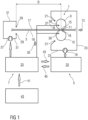
- Figure 1 shows a block diagram of a rolling stand 1 for rolling a rolling stock 3, a cooling and lubrication device 5 and an additional lubrication device 7.
- the rolling stock 3 is a metallic rolled strip, for example a steel strip, the thickness of which is reduced by rolling.
- the rolling stand 1 has two work rolls 9, 10 arranged one above the other, which are spaced from each other by a roll gap 11.
- the work rolls 9, 10 are set in rotation and the rolled stock 3 is pulled through the roll gap 11 by the rotating work rolls 9, 10 in a rolling direction 13.
- the rolled stock 3 is in contact with the work rolls 9, 10 in two contact zones 15, 16 in the region of the roll gap 11, with an upper contact surface 17 of the rolled stock 3 resting against the upper work roll 9 in a first contact zone 15 and a lower contact surface 18 of the rolled stock 3 resting against the lower work roll 10 in a second contact zone 16.
- the cooling lubricant is a cooling lubricant emulsion consisting of a cooling liquid and a lubricant, for example, water as the cooling liquid and oil as the lubricant, as well as possibly emulsifiers.
- the main component of the cooling lubricant emulsion is the cooling liquid, while the lubricant content of the cooling lubricant is only a few percent, for example, two to three percent.
- the cooling lubricant device 5 comprises a cooling lubricant pump 19, at least one cooling lubricant spray bar 21 for each work roll 9, 10, cooling lubricant lines 23, and a cooling lubricant control 25.
- Each cooling lubricant spray bar 21 comprises cooling lubricant nozzles for dispensing cooling lubricant onto the respective work roll 9, 10.
- the cooling lubricant is pumped by the cooling lubricant pump 19 through the cooling lubricant lines 23 to the cooling lubricant spray bars 21 and sprayed onto the work rolls 9, 10 by the cooling lubricant spray bars 21.
- the cooling lubricant quantities C dispensed by the cooling lubricant spray bars 21 are adjusted by the cooling lubricant control 25 by controlling the cooling lubricant pump 19.
- the rotation of the work rolls 9, 10 transports the cooling lubricant sprayed onto the work rolls 9, 10 to the contact zones 15, 16.
- an additional lubricant can be applied to the rolling stock 3.
- the additional lubricant is a pure lubricant, for example, a rolling oil.
- the additional lubrication device 7 comprises an additional lubricant pump 27, at least one Additional lubricant spray bars 29 for each contact surface 17, 18 of the rolling stock 3, additional lubricant lines 31, and an additional lubrication control 33.
- Each additional lubricant spray bar 29 has additional lubricant nozzles for dispensing additional lubricant onto the respective contact surface 17, 18.
- the additional lubricant is pumped by the additional lubricant pump 27 through the additional lubricant lines 31 to the additional lubricant spray bars 29 and sprayed onto the contact surfaces 17, 18 by the additional lubricant spray bars 29.
- the additional lubricant quantities A dispensed by the additional lubricant spray bars 29 are adjusted by the additional lubrication control 33 by controlling the additional lubricant pump 27.
- the movement of the rolling stock 3 transports the additional lubricant sprayed onto the contact surfaces 17, 18 to the contact zones 15, 16.
- the additional lubricant spray bars 29 are arranged at a predetermined application distance D with respect to the rolling direction 13 upstream of the roll gap 11 in order to apply the additional lubricant to the rolling stock 3 at this application distance D from the roll gap 11.
- the additional lubricant acts on the contact surfaces 17, 18 of the rolling stock 3 until it reaches the roll gap 11.
- the adhesion of the additional lubricant to the contact surfaces 17, 18 increases. This advantageously improves the lubricating effect (the so-called plate-out) of the additional lubricant in the contact zones 15, 16 compared to applying the additional lubricant to the contact surfaces 17, 18 immediately upstream of the roll gap 11.
- a lubrication requirement is determined for each contact zone 15, 16 as a function of at least one process parameter of the rolling process.
- a rolling stock speed v of the rolling stock 3 is used as a process parameter.
- the rolling stock speed v is determined, for example, by the additional lubrication control 33 from measurement signals 35 supplied to it by a strip speed sensor 37 for detecting a strip speed of the rolled strip.
- Optional further process parameters for determining the lubrication requirement are material properties 41 of the respective rolling stock 3, for example a compressive strength and/or a roughness of the rolling stock 3, which are supplied to the additional lubrication control 33 as material property data 41 from a production system 43.
- relative speeds between the contact surfaces 17, 18 of the rolling stock 3 at specified reference locations and the surfaces of the work rolls 9, 10 can optionally be used as process parameters for determining the lubrication requirement. These relative speeds can be determined, for example, from the rolling stock speed v at a reference location and measurement signals 35 from speed sensors 39 for recording the speeds of the work rolls 9, 10 as well as the thicknesses of the rolling stock 3 in front of and behind the roll gap 11. See, for example, equation (3.13) on page 113 in H. Hoffmann, R. Neugebauer, and G. Spur (eds.), "Handbuch Umformen,” 2nd edition, Carl Hanser Verlag, 2012, ISBN 978-3-446-42778-5.
- process parameters for determining the lubrication requirement are the viscosity of the cooling lubricant and/or the thickness of the rolling stock 3.
- the cooling lubricant quantities C currently present in the contact zones 15, 16 and/or the lubricant content of the cooling lubricant can also be recorded and used as process parameters.
- control data 45 can be exchanged between the cooling lubricant control 25 and the additional lubrication control 33 in order to coordinate the settings of the cooling lubricant quantities C and the additional lubricant quantities A.
- the additional lubricant is applied to each contact surface 17, 18 depending on the lubrication requirement determined for the contact zone 15, 16 of this contact surface 17, 18 if the cooling lubricant quantity C currently introduced into the contact zone 15, 16 does not cover the lubrication requirement determined for the contact zone 15, 16, for example because the rolling stock speed v changes or a rolling stock 3 with an increased compressive strength is rolled.
- the cooling lubricant quantities C applied to the work rolls 9, 10 are either kept constant or also adjusted depending on the at least one process parameter of the rolling process and/or on the additional lubricant quantities A applied to the contact surfaces 17, 18, see the description of Figure 2 .
- Figure 2 illustrates a method for rolling a rolling stock 3 with a rolling stand 1, a cooling lubrication device 5 and an additional lubrication device 7, each according to Figure 1 are trained.
- Figure 2 as a function of a time t, curves v(t), C(t), A(t) of a rolling stock speed v of the rolling stock 3, a cooling lubricant quantity C which is applied to a work roll 9, 10 of the rolling stand 1 by the cooling lubricant device 5, and an additional lubricant quantity A which is applied to a contact surface 17, 18 of the rolling stock 3 in a contact zone 15, 16 on the work roll 9, 10 by the additional lubricant device 7.
- the cooling lubricant quantity C and the additional lubricant quantity A are each defined as the volume applied per unit of time.
- Figure 2 shows a case in which the rolling stock 3 consists of various partial rolled strips that are welded together.
- a first partial rolled strip is rolled between times t 0 and t 4.
- a first transition area is formed between the first partial rolled strip and a second partial rolled strip with a first weld seam connecting these two partial rolled strips.
- the second partial rolled strip is then rolled between times t 5 and t 8.
- a second transition region between the second partial rolled strip and a third partial rolled strip with a second weld seam connecting these two partial rolled strips is then rolled between times t 8 and t 9.
- the third partial rolled strip is then rolled from time t 9.
- the second partial rolled strip has a higher compressive strength than the first partial rolled strip and the third partial rolled strip, which have the same compressive strength.
- the cooling lubricant quantity C and the additional lubricant quantity A are each adjusted by the cooling lubricant control 25 and the additional lubrication control 33 depending on a lubrication requirement, which is determined for the contact zone 15, 16 as a function of the rolling stock speed v and the compression strength of the respective sub-strip, as well as optionally by other process parameters mentioned above.
- Stribeck diagram is used, for example, for a friction coefficient of the friction between the contact surface 17, 18 and the work roll 9, 10 in the contact zone 15, 16 as a function of the process parameters, as can be seen, for example, from JBAF Smeulders, “Lubrication in the Cold Rolling Process Described by a 3D Stribeck Curve,” AISTech 2013 Proceedings, pp. 1681-1689 is known.
- the rolling stock speed v is significantly reduced from the second rolling stock speed v 2 to a third rolling stock speed v 3 in order to prepare the rolling of the first transition zone between the first partial rolled strip and the second partial rolled strip with the first weld seam.
- the first transition zone is then rolled between times t 4 and t 5 at the third rolling stock speed v 3 .
- the rolling stock speed v is increased between times t 5 and t 6 to a fourth rolling stock speed v 4 , at which the second partial rolled strip is rolled between times t 6 and t 7 .
- the lubrication requirement for rolling the first transition area increases compared to the lubrication requirement for rolling the first partial rolled strip due to the very low third rolling stock speed v 3 .
- the lubrication requirement for rolling the second partial rolled strip is even higher than the lubrication requirement for rolling the first transition area due to the high compressive strength of the second partial rolled strip. Therefore, additional lubricant is applied from time t 3 , whereby a larger amount of additional lubricant A is applied for rolling the second partial rolled strip between times t 6 and t 7 than for rolling the first transition area between times t 4 and t 5 .
- the applied cooling lubricant quantity C is reduced between times t 3 and t 6 and kept constant between times t 6 and t 7 in order to prevent or reduce the washing away of applied additional lubricant by the cooling lubricant.
- the rolling stock speed v is reduced from the fourth rolling stock speed v 4 back to the third rolling stock speed v 3 in order to prepare the rolling of the second transition zone between the second partial rolled strip and the third partial rolled strip with the second weld seam.
- the second transition zone is then rolled between times t 8 and t 9 at the third rolling stock speed v 3 .
- the rolling stock speed v is increased between times t 9 and t 10 to the second rolling stock speed v 2 , at which the third partial rolled strip is rolled between times t 10 and t 11 .
- the applied additional lubricant quantity A is initially reduced for rolling the second transition zone, and no additional lubricant is applied for rolling the third partial strip at the second rolling stock speed v 2 .
- the applied cooling lubricant quantity C is increased again.
- the rolling stock speed v is reduced from the second rolling stock speed v 2 to a fifth rolling stock speed v 5 , at which the third partial rolled strip is rolled from time t 12 .
- the rolling of the third partial strip at the fifth rolling speed v 5 requires lubrication that cannot be met with the cooling lubricant alone. Therefore, for the rolling of the third partial strip at the fifth rolling speed v 5 , additional lubricant is applied again and, at the same time, the applied cooling lubricant quantity C is reduced.
- the applied additional lubricant quantity A and the applied cooling lubricant quantity C are coordinated so that the lubrication requirement is met and the washing away of applied additional lubricant by the cooling lubricant is prevented or reduced. becomes.
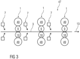
- Figure 3 shows schematically a rolling mill train 47 of a rolling mill with several rolling stands 1 arranged one behind the other for rolling a rolled product 3.
- the rolling stands 1 each have two work rolls 9, 10 arranged one above the other and a backup roll 49 for each work roll.
- the rolling mill train 47 has for each rolling stand 1 a Figure 3 not shown cooling and lubrication device 5 and an additional lubrication device 7.
- the cooling and lubrication devices 5 are each like the ones in Figure 1 cooling-lubricating device 5 shown and the additional lubricating devices 7 are each like the ones shown in Figure 1 illustrated additional lubrication device 7, wherein the additional lubricant spray bars 29 of each additional lubrication device 7 are arranged at the application distance D with respect to the rolling direction 13 in front of the roll gap 11 of the associated roll stand 1.
Landscapes
- Engineering & Computer Science (AREA)
- Mechanical Engineering (AREA)
- Metal Rolling (AREA)
- Lubricants (AREA)
Claims (11)
- Procédé de laminage d'une matière à laminer (3), dans lequel- la matière à laminer (3) est guidée, dans un sens de laminage (13), à travers une emprise (11) entre deux cylindres de travail (9, 10) d'une cage de laminoir (1),- dans une zone de contact (15, 16) dans laquelle une surface de contact (17, 18) de la matière à laminer (3) s'appuie contre un cylindre de travail (9, 10), un lubrifiant de refroidissement est introduit pour la lubrification de la zone de contact (15, 16),- un besoin en lubrification de la zone de contact (15, 16) est déterminé en fonction d'au moins un paramètre du processus de laminage,- un lubrifiant supplémentaire est appliqué sur la surface de contact (17, 18) de la matière à laminer (3), avant l'emprise (11) par rapport au sens de laminage (13), à une distance d'application (D) prédéfinie de l'emprise (11), lorsqu'une quantité de lubrifiant de refroidissement (C) introduite instantanément dans la zone de contact (15, 16) ne répond pas au besoin en lubrification, la distance d'application (D) étant dimensionnée de sorte qu'une adhérence du lubrifiant supplémentaire à la surface de contact (17, 18) est augmentée et que l'effet de lubrification du lubrifiant supplémentaire dans la zone de contact (15, 16) est amélioré par rapport à une application du lubrifiant supplémentaire sur la zone de contact (17, 18) directement avant l'emprise (11),- et la quantité de lubrifiant de refroidissement (C) introduite dans la zone de contact (15, 16) est réduite lorsque le lubrifiant supplémentaire est appliqué sur la surface de contact (17, 18),
caractérisé en ce que- l'on utilise, en tant que lubrifiant supplémentaire, un lubrifiant pur. - Procédé selon la revendication 1,
caractérisé en ce qu'une quantité de lubrifiant supplémentaire (A) appliquée sur la surface de contact (17, 18) de la matière à laminer (3) est ajustée en fonction du besoin en lubrification déterminé pour la zone de contact (15, 16). - Procédé selon l'une des revendications précédentes, caractérisé en ce que l'on utilise, en tant que paramètre de processus pour la détermination du besoin en lubrification, une vitesse (v) de la matière à laminer (3) et/ou une résistance à la compression de la matière à laminer (3) et/ou une rugosité de la matière à laminer (3) et/ou une vitesse relative entre la surface de contact (17, 18) de la matière à laminer (3) en un endroit de référence et la surface du cylindre de travail (9, 10) et/ou une épaisseur de la matière à laminer (3) et/ou une viscosité du lubrifiant de refroidissement.
- Procédé selon l'une des revendications précédentes, caractérisé en ce que la quantité de lubrifiant de refroidissement (C) introduite dans la zone de contact (15, 16) est ajustée en fonction de l'au moins un paramètre du processus de laminage.
- Procédé selon l'une des revendications précédentes, caractérisé en ce que le lubrifiant supplémentaire est appliqué par aspersion sur la matière à laminer (3).
- Procédé selon l'une des revendications précédentes, caractérisé en ce que le lubrifiant supplémentaire est appliqué uniformément sur la totalité de la largeur de la matière à laminer (3) sur la surface de contact (17, 18) de la matière à laminer (3).
- Procédé selon l'une des revendications précédentes, caractérisé en ce que le lubrifiant supplémentaire est appliqué sur la matière à laminer (3) à l'aide d'un dispositif pour lubrifiant supplémentaire (7) qui est indépendant d'un dispositif pour lubrifiant de refroidissement (5) destiné à l'introduction du lubrifiant de refroidissement dans la zone de contact (15, 16).
- Procédé selon l'une des revendications précédentes, caractérisé en ce que le besoin en lubrification de la zone de contact (15, 16) est déterminé avant le début du processus de laminage et/ou pendant le processus de laminage.
- Procédé selon l'une des revendications précédentes, caractérisé en ce que le besoin en lubrification de la zone de contact (15, 16) est déterminé en utilisant un diagramme de Stribeck pour un coefficient de frottement relatif au frottement entre la surface de contact (17, 18) et le cylindre de travail (9, 10) dans la zone de contact (15, 16) en fonction d'au moins un paramètre de processus.
- Procédé selon l'une des revendications précédentes, caractérisé en ce que le lubrifiant supplémentaire est appliqué sur deux surfaces de contact (17, 18) de la matière à laminer (3) opposées l'une à l'autre.
- Procédé selon la revendication 10, caractérisé en ce que des quantités de lubrifiant supplémentaire (A) différentes l'une de l'autre sont appliquées sur les deux surfaces de contact (17, 18) de la matière à laminer (3).
Applications Claiming Priority (2)
| Application Number | Priority Date | Filing Date | Title |
|---|---|---|---|
| EP16167662.2A EP3238843A1 (fr) | 2016-04-29 | 2016-04-29 | Procede de laminage d'un produit de laminage |
| PCT/EP2017/060193 WO2017186910A1 (fr) | 2016-04-29 | 2017-04-28 | Procédé pour laminer une matière à laminer |
Publications (3)
| Publication Number | Publication Date |
|---|---|
| EP3448592A1 EP3448592A1 (fr) | 2019-03-06 |
| EP3448592B1 EP3448592B1 (fr) | 2020-01-22 |
| EP3448592B2 true EP3448592B2 (fr) | 2025-04-23 |
Family
ID=55860772
Family Applications (2)
| Application Number | Title | Priority Date | Filing Date |
|---|---|---|---|
| EP16167662.2A Withdrawn EP3238843A1 (fr) | 2016-04-29 | 2016-04-29 | Procede de laminage d'un produit de laminage |
| EP17723941.5A Active EP3448592B2 (fr) | 2016-04-29 | 2017-04-28 | Procede de laminage d'un produit de laminage |
Family Applications Before (1)
| Application Number | Title | Priority Date | Filing Date |
|---|---|---|---|
| EP16167662.2A Withdrawn EP3238843A1 (fr) | 2016-04-29 | 2016-04-29 | Procede de laminage d'un produit de laminage |
Country Status (7)
| Country | Link |
|---|---|
| US (1) | US11161161B2 (fr) |
| EP (2) | EP3238843A1 (fr) |
| JP (1) | JP6820349B2 (fr) |
| CN (1) | CN109070162B (fr) |
| MX (1) | MX392195B (fr) |
| RU (1) | RU2701916C1 (fr) |
| WO (1) | WO2017186910A1 (fr) |
Families Citing this family (1)
| Publication number | Priority date | Publication date | Assignee | Title |
|---|---|---|---|---|
| EP4501480A1 (fr) * | 2023-08-03 | 2025-02-05 | Primetals Technologies Austria GmbH | Procédé et système pour l'application d'un lubrifiant lors du laminage à froid d'un produit à laminer dans une cage de laminoir |
Citations (1)
| Publication number | Priority date | Publication date | Assignee | Title |
|---|---|---|---|---|
| JP2001321809A (ja) † | 2000-05-19 | 2001-11-20 | Nkk Corp | 鋼帯の冷間圧延方法 |
Family Cites Families (28)
| Publication number | Priority date | Publication date | Assignee | Title |
|---|---|---|---|---|
| SU1015941A1 (ru) * | 1982-01-06 | 1983-05-07 | Предприятие П/Я Р-6335 | Способ подачи смазочно-охлаждающей жидкости |
| JPH01218710A (ja) * | 1988-02-29 | 1989-08-31 | Nippon Steel Corp | 冷間タンデム圧延における圧延潤骨およびロール冷却方法 |
| RU1795920C (ru) | 1991-01-21 | 1993-02-15 | Магнитогорский металлургический комбинат им.В.И.Ленина | Способ очистки поверхности полосы при холодной прокатке |
| JP3615813B2 (ja) | 1994-12-28 | 2005-02-02 | 株式会社日立製作所 | 作業ロールクロス圧延機のロール間潤滑油供給システム |
| JPH09239429A (ja) | 1996-03-05 | 1997-09-16 | Hitachi Ltd | 冷間圧延機および冷間圧延方法 |
| JPH11244925A (ja) | 1998-02-26 | 1999-09-14 | Nippon Steel Corp | 冷間圧延方法及び装置 |
| JP2000280002A (ja) | 1999-03-31 | 2000-10-10 | Kawasaki Steel Corp | 帯板の冷間タンデム圧延方法および冷間タンデム圧延機 |
| DE19918880A1 (de) | 1999-04-26 | 2000-11-02 | Sms Demag Ag | Walzverfahren für ein Metallband und hiermit korrespondierende Walzanordnung |
| WO2001066277A1 (fr) | 2000-03-09 | 2001-09-13 | Nkk Corporation | Procede d'alimentation en huile de laminage, pour laminage a froid |
| JP2002282926A (ja) | 2001-03-27 | 2002-10-02 | Kawasaki Steel Corp | 圧延制御方法 |
| US6675622B2 (en) | 2001-05-01 | 2004-01-13 | Air Products And Chemicals, Inc. | Process and roll stand for cold rolling of a metal strip |
| DE10352546A1 (de) | 2003-09-04 | 2005-03-31 | Sms Demag Ag | Verfahren und Vorrichtung zum Aufbringen einer regelbaren Zugspannungsverteilung, insbesondere in den Kantenbereichen kaltgewalzter Metallbänder |
| JP2005193242A (ja) | 2003-12-26 | 2005-07-21 | Jfe Steel Kk | 金属板の冷間タンデム圧延方法および冷間タンデム圧延機 |
| DE102004025058A1 (de) | 2004-05-18 | 2005-12-08 | Sms Demag Ag | Verfahren und Vorrichtung zur Kühlung und/oder Schmierung von Walzen und/oder Walzgut |
| DE102004040375A1 (de) * | 2004-06-09 | 2005-12-29 | Sms Demag Ag | Verfahren und Walzgerüst zum Kaltwalzen von metallischem Walzgut, insbesondere von Walzband, mit Düsen für gasförmige oder flüssige Behandlungsmedien |
| JP2006224141A (ja) | 2005-02-17 | 2006-08-31 | Nippon Steel Corp | 冷間圧延における潤滑油供給設備および冷間圧延方法 |
| JP4654724B2 (ja) | 2005-03-24 | 2011-03-23 | Jfeスチール株式会社 | 冷間圧延における圧延油供給方法および装置 |
| JP4760083B2 (ja) | 2005-03-25 | 2011-08-31 | Jfeスチール株式会社 | 板材の圧延方法及び装置 |
| DE102005042020A1 (de) * | 2005-09-02 | 2007-03-08 | Sms Demag Ag | Verfahren zum Schmieren und Kühlen von Walzen und Metallband beim Walzen, insbesondere beim Kaltwalzen, von Metallbändern |
| CN100443202C (zh) * | 2005-09-13 | 2008-12-17 | 北京伟世杰液压设备有限公司 | 轴承的润滑冷却方法及装置 |
| JP4640157B2 (ja) | 2005-12-15 | 2011-03-02 | Jfeスチール株式会社 | 冷間圧延方法及び装置 |
| JP4924398B2 (ja) | 2007-12-13 | 2012-04-25 | Jfeスチール株式会社 | 冷間圧延における潤滑油供給方法 |
| JP2011200877A (ja) | 2010-03-24 | 2011-10-13 | Jfe Steel Corp | 金属帯の冷間圧延方法 |
| EP2465619A1 (fr) | 2010-12-16 | 2012-06-20 | Siemens VAI Metals Technologies GmbH | Procédé et dispositif d'application d'un lubrifiant lors du laminage d'un produit de laminage métallique |
| EP2750813B2 (fr) | 2011-08-30 | 2019-11-06 | Primetals Technologies Austria GmbH | Laminoir réversible et procédé de fonctionnement pour un laminoir réversible |
| PL2572807T3 (pl) * | 2011-09-22 | 2014-11-28 | Constantia Teich Gmbh | Sposób wytwarzania folii aluminiowej ze zintegrowanymi cechami zabezpieczającymi |
| US9566623B2 (en) | 2012-02-15 | 2017-02-14 | Primetals Technologies Austria GmbH | Low maintenance nozzle mixer unit for roll nip lubrication |
| JP6455683B2 (ja) * | 2016-04-21 | 2019-01-23 | Jfeスチール株式会社 | 金属帯の冷間圧延設備および冷間圧延方法 |
-
2016
- 2016-04-29 EP EP16167662.2A patent/EP3238843A1/fr not_active Withdrawn
-
2017
- 2017-04-28 JP JP2018556441A patent/JP6820349B2/ja active Active
- 2017-04-28 CN CN201780026643.5A patent/CN109070162B/zh active Active
- 2017-04-28 EP EP17723941.5A patent/EP3448592B2/fr active Active
- 2017-04-28 MX MX2018012916A patent/MX392195B/es unknown
- 2017-04-28 WO PCT/EP2017/060193 patent/WO2017186910A1/fr not_active Ceased
- 2017-04-28 RU RU2018133704A patent/RU2701916C1/ru active
- 2017-04-28 US US16/094,911 patent/US11161161B2/en active Active
Patent Citations (1)
| Publication number | Priority date | Publication date | Assignee | Title |
|---|---|---|---|---|
| JP2001321809A (ja) † | 2000-05-19 | 2001-11-20 | Nkk Corp | 鋼帯の冷間圧延方法 |
Also Published As
| Publication number | Publication date |
|---|---|
| MX392195B (es) | 2025-03-21 |
| MX2018012916A (es) | 2019-05-22 |
| JP2019514693A (ja) | 2019-06-06 |
| US20190151919A1 (en) | 2019-05-23 |
| US11161161B2 (en) | 2021-11-02 |
| JP6820349B2 (ja) | 2021-01-27 |
| EP3448592A1 (fr) | 2019-03-06 |
| EP3238843A1 (fr) | 2017-11-01 |
| RU2701916C1 (ru) | 2019-10-02 |
| EP3448592B1 (fr) | 2020-01-22 |
| CN109070162A (zh) | 2018-12-21 |
| CN109070162B (zh) | 2020-12-08 |
| WO2017186910A1 (fr) | 2017-11-02 |
Similar Documents
| Publication | Publication Date | Title |
|---|---|---|
| EP2548665B1 (fr) | Procédé de détermination de l'usure dépendant du mouvement relatif d'un cylindre | |
| DE69710817T2 (de) | Walzverfahren und Walzwerk für Band zur Reduzierung der Kantenanschärfung | |
| EP3107666B1 (fr) | Précommande simple du pas de filetage d'un ébaucheur | |
| EP0121148B1 (fr) | Procédé pour la fabrication de feuillard à chaud avec section et planéité de bande de haute qualité | |
| EP2712332B1 (fr) | Procédé de commande pour un train à feuillards à chaud | |
| EP2603337B1 (fr) | Procédé de production de laminés à l'aide d'une installation combinée de laminage direct, dispositif de commande et/ou de régulation pour une installation combinée de laminage direct, et installation combinée de laminage direct | |
| EP1732716B1 (fr) | Procede pour produire un metal | |
| EP2566989B1 (fr) | Procédé de laminage à chaud de bandes d'acier et train de laminage à chaud | |
| DE60016999T2 (de) | Verfahren und Vorrichtung zum Regeln der Bandform beim Bandwalzen | |
| EP3791971A1 (fr) | Laminage à froid d'un article à laminer dans un train de laminage pourvu d'une pluralité de cages de laminoir | |
| EP2644719A1 (fr) | Commande de refroidissement | |
| EP2662158A1 (fr) | Procédé de traitement de produits à laminer et laminoir | |
| EP2741870A1 (fr) | Installation de laminage et procédé de laminage | |
| EP3448592B2 (fr) | Procede de laminage d'un produit de laminage | |
| EP3362199B1 (fr) | Procédé pour laminer une matière à laminer et laminoir | |
| EP3941655B1 (fr) | Installation et procédé pour fabriquer un feuillard à chaud métallique | |
| EP3810347B1 (fr) | Procédé et cage de laminoir pour laminer un produit de laminage | |
| EP3840896B1 (fr) | Procédé et dispositif de commande d'un laminoir étireur-réducteur pour la compensation de l'épaisseur de paroi | |
| EP3733317B1 (fr) | Laminage d'un laminé | |
| DE3401894A1 (de) | Verfahren zum herstellen von walzband mit hoher bandprofil- und bandplanheitsguete | |
| DE68901941T2 (de) | Kontinuierlich arbeitende schmelzgalvanisiervorrichtung. | |
| EP3517228A1 (fr) | Règles d'un processus de laminage | |
| EP0054172A2 (fr) | Procédé et installation pour le laminage d'une bande détensionnée | |
| DE10206758B4 (de) | Bandkanten-Planheitssteuerung | |
| EP1827735B1 (fr) | Procede et dispositif de coulee en bande de metaux |
Legal Events
| Date | Code | Title | Description |
|---|---|---|---|
| STAA | Information on the status of an ep patent application or granted ep patent |
Free format text: STATUS: UNKNOWN |
|
| STAA | Information on the status of an ep patent application or granted ep patent |
Free format text: STATUS: THE INTERNATIONAL PUBLICATION HAS BEEN MADE |
|
| TPAC | Observations filed by third parties |
Free format text: ORIGINAL CODE: EPIDOSNTIPA |
|
| PUAI | Public reference made under article 153(3) epc to a published international application that has entered the european phase |
Free format text: ORIGINAL CODE: 0009012 |
|
| STAA | Information on the status of an ep patent application or granted ep patent |
Free format text: STATUS: REQUEST FOR EXAMINATION WAS MADE |
|
| 17P | Request for examination filed |
Effective date: 20181129 |
|
| AK | Designated contracting states |
Kind code of ref document: A1 Designated state(s): AL AT BE BG CH CY CZ DE DK EE ES FI FR GB GR HR HU IE IS IT LI LT LU LV MC MK MT NL NO PL PT RO RS SE SI SK SM TR |
|
| AX | Request for extension of the european patent |
Extension state: BA ME |
|
| DAV | Request for validation of the european patent (deleted) | ||
| DAX | Request for extension of the european patent (deleted) | ||
| GRAP | Despatch of communication of intention to grant a patent |
Free format text: ORIGINAL CODE: EPIDOSNIGR1 |
|
| STAA | Information on the status of an ep patent application or granted ep patent |
Free format text: STATUS: GRANT OF PATENT IS INTENDED |
|
| INTG | Intention to grant announced |
Effective date: 20190913 |
|
| GRAS | Grant fee paid |
Free format text: ORIGINAL CODE: EPIDOSNIGR3 |
|
| GRAA | (expected) grant |
Free format text: ORIGINAL CODE: 0009210 |
|
| STAA | Information on the status of an ep patent application or granted ep patent |
Free format text: STATUS: THE PATENT HAS BEEN GRANTED |
|
| AK | Designated contracting states |
Kind code of ref document: B1 Designated state(s): AL AT BE BG CH CY CZ DE DK EE ES FI FR GB GR HR HU IE IS IT LI LT LU LV MC MK MT NL NO PL PT RO RS SE SI SK SM TR |
|
| REG | Reference to a national code |
Ref country code: GB Ref legal event code: FG4D Free format text: NOT ENGLISH |
|
| REG | Reference to a national code |
Ref country code: CH Ref legal event code: EP |
|
| REG | Reference to a national code |
Ref country code: AT Ref legal event code: REF Ref document number: 1226595 Country of ref document: AT Kind code of ref document: T Effective date: 20200215 |
|
| REG | Reference to a national code |
Ref country code: IE Ref legal event code: FG4D Free format text: LANGUAGE OF EP DOCUMENT: GERMAN |
|
| REG | Reference to a national code |
Ref country code: DE Ref legal event code: R096 Ref document number: 502017003546 Country of ref document: DE |
|
| REG | Reference to a national code |
Ref country code: NL Ref legal event code: MP Effective date: 20200122 |
|
| REG | Reference to a national code |
Ref country code: LT Ref legal event code: MG4D |
|
| PG25 | Lapsed in a contracting state [announced via postgrant information from national office to epo] |
Ref country code: FI Free format text: LAPSE BECAUSE OF FAILURE TO SUBMIT A TRANSLATION OF THE DESCRIPTION OR TO PAY THE FEE WITHIN THE PRESCRIBED TIME-LIMIT Effective date: 20200122 Ref country code: NO Free format text: LAPSE BECAUSE OF FAILURE TO SUBMIT A TRANSLATION OF THE DESCRIPTION OR TO PAY THE FEE WITHIN THE PRESCRIBED TIME-LIMIT Effective date: 20200422 Ref country code: NL Free format text: LAPSE BECAUSE OF FAILURE TO SUBMIT A TRANSLATION OF THE DESCRIPTION OR TO PAY THE FEE WITHIN THE PRESCRIBED TIME-LIMIT Effective date: 20200122 Ref country code: RS Free format text: LAPSE BECAUSE OF FAILURE TO SUBMIT A TRANSLATION OF THE DESCRIPTION OR TO PAY THE FEE WITHIN THE PRESCRIBED TIME-LIMIT Effective date: 20200122 Ref country code: PT Free format text: LAPSE BECAUSE OF FAILURE TO SUBMIT A TRANSLATION OF THE DESCRIPTION OR TO PAY THE FEE WITHIN THE PRESCRIBED TIME-LIMIT Effective date: 20200614 |
|
| PG25 | Lapsed in a contracting state [announced via postgrant information from national office to epo] |
Ref country code: BG Free format text: LAPSE BECAUSE OF FAILURE TO SUBMIT A TRANSLATION OF THE DESCRIPTION OR TO PAY THE FEE WITHIN THE PRESCRIBED TIME-LIMIT Effective date: 20200422 Ref country code: HR Free format text: LAPSE BECAUSE OF FAILURE TO SUBMIT A TRANSLATION OF THE DESCRIPTION OR TO PAY THE FEE WITHIN THE PRESCRIBED TIME-LIMIT Effective date: 20200122 Ref country code: GR Free format text: LAPSE BECAUSE OF FAILURE TO SUBMIT A TRANSLATION OF THE DESCRIPTION OR TO PAY THE FEE WITHIN THE PRESCRIBED TIME-LIMIT Effective date: 20200423 Ref country code: IS Free format text: LAPSE BECAUSE OF FAILURE TO SUBMIT A TRANSLATION OF THE DESCRIPTION OR TO PAY THE FEE WITHIN THE PRESCRIBED TIME-LIMIT Effective date: 20200522 Ref country code: LV Free format text: LAPSE BECAUSE OF FAILURE TO SUBMIT A TRANSLATION OF THE DESCRIPTION OR TO PAY THE FEE WITHIN THE PRESCRIBED TIME-LIMIT Effective date: 20200122 Ref country code: SE Free format text: LAPSE BECAUSE OF FAILURE TO SUBMIT A TRANSLATION OF THE DESCRIPTION OR TO PAY THE FEE WITHIN THE PRESCRIBED TIME-LIMIT Effective date: 20200122 |
|
| REG | Reference to a national code |
Ref country code: DE Ref legal event code: R026 Ref document number: 502017003546 Country of ref document: DE |
|
| PLBI | Opposition filed |
Free format text: ORIGINAL CODE: 0009260 |
|
| PG25 | Lapsed in a contracting state [announced via postgrant information from national office to epo] |
Ref country code: ES Free format text: LAPSE BECAUSE OF FAILURE TO SUBMIT A TRANSLATION OF THE DESCRIPTION OR TO PAY THE FEE WITHIN THE PRESCRIBED TIME-LIMIT Effective date: 20200122 Ref country code: LT Free format text: LAPSE BECAUSE OF FAILURE TO SUBMIT A TRANSLATION OF THE DESCRIPTION OR TO PAY THE FEE WITHIN THE PRESCRIBED TIME-LIMIT Effective date: 20200122 Ref country code: SK Free format text: LAPSE BECAUSE OF FAILURE TO SUBMIT A TRANSLATION OF THE DESCRIPTION OR TO PAY THE FEE WITHIN THE PRESCRIBED TIME-LIMIT Effective date: 20200122 Ref country code: CZ Free format text: LAPSE BECAUSE OF FAILURE TO SUBMIT A TRANSLATION OF THE DESCRIPTION OR TO PAY THE FEE WITHIN THE PRESCRIBED TIME-LIMIT Effective date: 20200122 Ref country code: RO Free format text: LAPSE BECAUSE OF FAILURE TO SUBMIT A TRANSLATION OF THE DESCRIPTION OR TO PAY THE FEE WITHIN THE PRESCRIBED TIME-LIMIT Effective date: 20200122 Ref country code: EE Free format text: LAPSE BECAUSE OF FAILURE TO SUBMIT A TRANSLATION OF THE DESCRIPTION OR TO PAY THE FEE WITHIN THE PRESCRIBED TIME-LIMIT Effective date: 20200122 Ref country code: DK Free format text: LAPSE BECAUSE OF FAILURE TO SUBMIT A TRANSLATION OF THE DESCRIPTION OR TO PAY THE FEE WITHIN THE PRESCRIBED TIME-LIMIT Effective date: 20200122 Ref country code: SM Free format text: LAPSE BECAUSE OF FAILURE TO SUBMIT A TRANSLATION OF THE DESCRIPTION OR TO PAY THE FEE WITHIN THE PRESCRIBED TIME-LIMIT Effective date: 20200122 |
|
| PLAX | Notice of opposition and request to file observation + time limit sent |
Free format text: ORIGINAL CODE: EPIDOSNOBS2 |
|
| 26 | Opposition filed |
Opponent name: SMS GROUP GMBH Effective date: 20201022 |
|
| PG25 | Lapsed in a contracting state [announced via postgrant information from national office to epo] |
Ref country code: MC Free format text: LAPSE BECAUSE OF FAILURE TO SUBMIT A TRANSLATION OF THE DESCRIPTION OR TO PAY THE FEE WITHIN THE PRESCRIBED TIME-LIMIT Effective date: 20200122 |
|
| REG | Reference to a national code |
Ref country code: CH Ref legal event code: PL |
|
| PG25 | Lapsed in a contracting state [announced via postgrant information from national office to epo] |
Ref country code: LI Free format text: LAPSE BECAUSE OF NON-PAYMENT OF DUE FEES Effective date: 20200430 Ref country code: FR Free format text: LAPSE BECAUSE OF NON-PAYMENT OF DUE FEES Effective date: 20200430 Ref country code: CH Free format text: LAPSE BECAUSE OF NON-PAYMENT OF DUE FEES Effective date: 20200430 Ref country code: LU Free format text: LAPSE BECAUSE OF NON-PAYMENT OF DUE FEES Effective date: 20200428 |
|
| REG | Reference to a national code |
Ref country code: BE Ref legal event code: MM Effective date: 20200430 |
|
| PG25 | Lapsed in a contracting state [announced via postgrant information from national office to epo] |
Ref country code: SI Free format text: LAPSE BECAUSE OF FAILURE TO SUBMIT A TRANSLATION OF THE DESCRIPTION OR TO PAY THE FEE WITHIN THE PRESCRIBED TIME-LIMIT Effective date: 20200122 Ref country code: BE Free format text: LAPSE BECAUSE OF NON-PAYMENT OF DUE FEES Effective date: 20200430 Ref country code: PL Free format text: LAPSE BECAUSE OF FAILURE TO SUBMIT A TRANSLATION OF THE DESCRIPTION OR TO PAY THE FEE WITHIN THE PRESCRIBED TIME-LIMIT Effective date: 20200122 |
|
| PLBB | Reply of patent proprietor to notice(s) of opposition received |
Free format text: ORIGINAL CODE: EPIDOSNOBS3 |
|
| PG25 | Lapsed in a contracting state [announced via postgrant information from national office to epo] |
Ref country code: IE Free format text: LAPSE BECAUSE OF NON-PAYMENT OF DUE FEES Effective date: 20200428 |
|
| GBPC | Gb: european patent ceased through non-payment of renewal fee |
Effective date: 20210428 |
|
| PG25 | Lapsed in a contracting state [announced via postgrant information from national office to epo] |
Ref country code: GB Free format text: LAPSE BECAUSE OF NON-PAYMENT OF DUE FEES Effective date: 20210428 |
|
| PG25 | Lapsed in a contracting state [announced via postgrant information from national office to epo] |
Ref country code: TR Free format text: LAPSE BECAUSE OF FAILURE TO SUBMIT A TRANSLATION OF THE DESCRIPTION OR TO PAY THE FEE WITHIN THE PRESCRIBED TIME-LIMIT Effective date: 20200122 Ref country code: MT Free format text: LAPSE BECAUSE OF FAILURE TO SUBMIT A TRANSLATION OF THE DESCRIPTION OR TO PAY THE FEE WITHIN THE PRESCRIBED TIME-LIMIT Effective date: 20200122 Ref country code: CY Free format text: LAPSE BECAUSE OF FAILURE TO SUBMIT A TRANSLATION OF THE DESCRIPTION OR TO PAY THE FEE WITHIN THE PRESCRIBED TIME-LIMIT Effective date: 20200122 |
|
| PG25 | Lapsed in a contracting state [announced via postgrant information from national office to epo] |
Ref country code: MK Free format text: LAPSE BECAUSE OF FAILURE TO SUBMIT A TRANSLATION OF THE DESCRIPTION OR TO PAY THE FEE WITHIN THE PRESCRIBED TIME-LIMIT Effective date: 20200122 Ref country code: AL Free format text: LAPSE BECAUSE OF FAILURE TO SUBMIT A TRANSLATION OF THE DESCRIPTION OR TO PAY THE FEE WITHIN THE PRESCRIBED TIME-LIMIT Effective date: 20200122 |
|
| APAH | Appeal reference modified |
Free format text: ORIGINAL CODE: EPIDOSCREFNO |
|
| APBM | Appeal reference recorded |
Free format text: ORIGINAL CODE: EPIDOSNREFNO |
|
| APBP | Date of receipt of notice of appeal recorded |
Free format text: ORIGINAL CODE: EPIDOSNNOA2O |
|
| APBQ | Date of receipt of statement of grounds of appeal recorded |
Free format text: ORIGINAL CODE: EPIDOSNNOA3O |
|
| P01 | Opt-out of the competence of the unified patent court (upc) registered |
Effective date: 20230614 |
|
| APAH | Appeal reference modified |
Free format text: ORIGINAL CODE: EPIDOSCREFNO |
|
| APBU | Appeal procedure closed |
Free format text: ORIGINAL CODE: EPIDOSNNOA9O |
|
| PUAH | Patent maintained in amended form |
Free format text: ORIGINAL CODE: 0009272 |
|
| STAA | Information on the status of an ep patent application or granted ep patent |
Free format text: STATUS: PATENT MAINTAINED AS AMENDED |
|
| 27A | Patent maintained in amended form |
Effective date: 20250423 |
|
| AK | Designated contracting states |
Kind code of ref document: B2 Designated state(s): AL AT BE BG CH CY CZ DE DK EE ES FI FR GB GR HR HU IE IS IT LI LT LU LV MC MK MT NL NO PL PT RO RS SE SI SK SM TR |
|
| REG | Reference to a national code |
Ref country code: DE Ref legal event code: R102 Ref document number: 502017003546 Country of ref document: DE |
|
| PGFP | Annual fee paid to national office [announced via postgrant information from national office to epo] |
Ref country code: DE Payment date: 20250422 Year of fee payment: 9 |
|
| PGFP | Annual fee paid to national office [announced via postgrant information from national office to epo] |
Ref country code: IT Payment date: 20250424 Year of fee payment: 9 |
|
| REG | Reference to a national code |
Ref country code: DE Ref legal event code: R082 Ref document number: 502017003546 Country of ref document: DE Representative=s name: LINDNER BLAUMEIER, PATENT- UND RECHTSANWAELTE,, DE |
|
| PGFP | Annual fee paid to national office [announced via postgrant information from national office to epo] |
Ref country code: AT Payment date: 20250423 Year of fee payment: 9 |