EP3448277B1 - Appareils de thrombectomie à tracteur à inversion préchargé - Google Patents
Appareils de thrombectomie à tracteur à inversion préchargé Download PDFInfo
- Publication number
- EP3448277B1 EP3448277B1 EP17722277.5A EP17722277A EP3448277B1 EP 3448277 B1 EP3448277 B1 EP 3448277B1 EP 17722277 A EP17722277 A EP 17722277A EP 3448277 B1 EP3448277 B1 EP 3448277B1
- Authority
- EP
- European Patent Office
- Prior art keywords
- tractor
- catheter
- distal end
- puller
- region
- Prior art date
- Legal status (The legal status is an assumption and is not a legal conclusion. Google has not performed a legal analysis and makes no representation as to the accuracy of the status listed.)
- Active
Links
- 238000013151 thrombectomy Methods 0.000 title claims description 50
- 238000005096 rolling process Methods 0.000 claims description 17
- 230000023597 hemostasis Effects 0.000 claims description 2
- 239000000463 material Substances 0.000 description 30
- 238000000034 method Methods 0.000 description 19
- 208000007536 Thrombosis Diseases 0.000 description 15
- 238000000576 coating method Methods 0.000 description 14
- 239000011248 coating agent Substances 0.000 description 10
- 230000002028 premature Effects 0.000 description 10
- 239000000853 adhesive Substances 0.000 description 6
- 230000001070 adhesive effect Effects 0.000 description 6
- 210000001367 artery Anatomy 0.000 description 5
- 210000004369 blood Anatomy 0.000 description 5
- 239000008280 blood Substances 0.000 description 5
- 230000007704 transition Effects 0.000 description 5
- 230000009286 beneficial effect Effects 0.000 description 4
- 230000005660 hydrophilic surface Effects 0.000 description 4
- -1 polyethylene Polymers 0.000 description 4
- 210000001519 tissue Anatomy 0.000 description 4
- QVGXLLKOCUKJST-UHFFFAOYSA-N atomic oxygen Chemical compound [O] QVGXLLKOCUKJST-UHFFFAOYSA-N 0.000 description 3
- 210000004204 blood vessel Anatomy 0.000 description 3
- 239000012530 fluid Substances 0.000 description 3
- 230000005661 hydrophobic surface Effects 0.000 description 3
- 208000028867 ischemia Diseases 0.000 description 3
- 230000033001 locomotion Effects 0.000 description 3
- 229910052760 oxygen Inorganic materials 0.000 description 3
- 239000001301 oxygen Substances 0.000 description 3
- 229920001343 polytetrafluoroethylene Polymers 0.000 description 3
- 239000004810 polytetrafluoroethylene Substances 0.000 description 3
- 206010021143 Hypoxia Diseases 0.000 description 2
- 239000004433 Thermoplastic polyurethane Substances 0.000 description 2
- 230000001154 acute effect Effects 0.000 description 2
- 230000017531 blood circulation Effects 0.000 description 2
- 210000001715 carotid artery Anatomy 0.000 description 2
- 230000006835 compression Effects 0.000 description 2
- 238000007906 compression Methods 0.000 description 2
- 210000004351 coronary vessel Anatomy 0.000 description 2
- 230000003247 decreasing effect Effects 0.000 description 2
- 201000010099 disease Diseases 0.000 description 2
- 208000037265 diseases, disorders, signs and symptoms Diseases 0.000 description 2
- 238000009998 heat setting Methods 0.000 description 2
- 238000003384 imaging method Methods 0.000 description 2
- 239000003550 marker Substances 0.000 description 2
- 210000004165 myocardium Anatomy 0.000 description 2
- 230000002093 peripheral effect Effects 0.000 description 2
- 229920000139 polyethylene terephthalate Polymers 0.000 description 2
- 239000005020 polyethylene terephthalate Substances 0.000 description 2
- 229920001296 polysiloxane Polymers 0.000 description 2
- 239000007787 solid Substances 0.000 description 2
- 229920002803 thermoplastic polyurethane Polymers 0.000 description 2
- 230000002792 vascular Effects 0.000 description 2
- 210000005166 vasculature Anatomy 0.000 description 2
- 206010002383 Angina Pectoris Diseases 0.000 description 1
- 201000001320 Atherosclerosis Diseases 0.000 description 1
- 206010008479 Chest Pain Diseases 0.000 description 1
- 206010013975 Dyspnoeas Diseases 0.000 description 1
- 239000004677 Nylon Substances 0.000 description 1
- 239000004696 Poly ether ether ketone Substances 0.000 description 1
- 229920002614 Polyether block amide Polymers 0.000 description 1
- 239000004698 Polyethylene Substances 0.000 description 1
- 239000004743 Polypropylene Substances 0.000 description 1
- 230000002411 adverse Effects 0.000 description 1
- 238000002266 amputation Methods 0.000 description 1
- 210000003484 anatomy Anatomy 0.000 description 1
- 239000003146 anticoagulant agent Substances 0.000 description 1
- 229940127219 anticoagulant drug Drugs 0.000 description 1
- 230000003143 atherosclerotic effect Effects 0.000 description 1
- JUPQTSLXMOCDHR-UHFFFAOYSA-N benzene-1,4-diol;bis(4-fluorophenyl)methanone Chemical compound OC1=CC=C(O)C=C1.C1=CC(F)=CC=C1C(=O)C1=CC=C(F)C=C1 JUPQTSLXMOCDHR-UHFFFAOYSA-N 0.000 description 1
- 230000015572 biosynthetic process Effects 0.000 description 1
- 230000000903 blocking effect Effects 0.000 description 1
- 210000000746 body region Anatomy 0.000 description 1
- 210000004004 carotid artery internal Anatomy 0.000 description 1
- 230000030833 cell death Effects 0.000 description 1
- 239000003795 chemical substances by application Substances 0.000 description 1
- 238000010276 construction Methods 0.000 description 1
- 238000005520 cutting process Methods 0.000 description 1
- 230000034994 death Effects 0.000 description 1
- 230000001419 dependent effect Effects 0.000 description 1
- 238000004090 dissolution Methods 0.000 description 1
- 229940079593 drug Drugs 0.000 description 1
- 239000003814 drug Substances 0.000 description 1
- 230000000694 effects Effects 0.000 description 1
- 210000003743 erythrocyte Anatomy 0.000 description 1
- 239000000835 fiber Substances 0.000 description 1
- 238000002594 fluoroscopy Methods 0.000 description 1
- 238000013467 fragmentation Methods 0.000 description 1
- 238000006062 fragmentation reaction Methods 0.000 description 1
- 239000003292 glue Substances 0.000 description 1
- XEOCKQIQXJNTER-UHFFFAOYSA-N gold palladium platinum Chemical compound [Pd].[Pd].[Pd].[Pd].[Pd].[Pt].[Pt].[Pt].[Pt].[Pt].[Pt].[Au].[Au].[Au].[Au].[Au].[Au].[Au].[Au].[Au].[Au].[Au].[Au].[Au].[Au].[Au].[Au].[Au].[Au].[Au].[Au].[Au].[Au].[Au].[Au].[Au].[Au].[Au].[Au].[Au].[Au].[Au].[Au].[Au].[Au].[Au].[Au].[Au].[Au].[Au].[Au].[Au].[Au].[Au].[Au].[Au].[Au].[Au].[Au].[Au].[Au].[Au].[Au].[Au].[Au].[Au].[Au].[Au].[Au].[Au].[Au].[Au].[Au].[Au].[Au].[Au].[Au].[Au].[Au].[Au].[Au].[Au].[Au].[Au].[Au].[Au].[Au].[Au].[Au].[Au].[Au].[Au].[Au].[Au].[Au].[Au].[Au].[Au] XEOCKQIQXJNTER-UHFFFAOYSA-N 0.000 description 1
- 230000003116 impacting effect Effects 0.000 description 1
- 230000002401 inhibitory effect Effects 0.000 description 1
- 208000014674 injury Diseases 0.000 description 1
- 230000001788 irregular Effects 0.000 description 1
- 238000003698 laser cutting Methods 0.000 description 1
- 230000014759 maintenance of location Effects 0.000 description 1
- 238000002844 melting Methods 0.000 description 1
- 230000008018 melting Effects 0.000 description 1
- 210000003205 muscle Anatomy 0.000 description 1
- 230000003387 muscular Effects 0.000 description 1
- 230000002107 myocardial effect Effects 0.000 description 1
- 208000010125 myocardial infarction Diseases 0.000 description 1
- 210000005036 nerve Anatomy 0.000 description 1
- 229910001000 nickel titanium Inorganic materials 0.000 description 1
- 229920001778 nylon Polymers 0.000 description 1
- 229920002530 polyetherether ketone Polymers 0.000 description 1
- 229920000573 polyethylene Polymers 0.000 description 1
- 229920000098 polyolefin Polymers 0.000 description 1
- 229920001155 polypropylene Polymers 0.000 description 1
- 230000000717 retained effect Effects 0.000 description 1
- 238000007790 scraping Methods 0.000 description 1
- 238000004904 shortening Methods 0.000 description 1
- 229910001220 stainless steel Inorganic materials 0.000 description 1
- 239000010935 stainless steel Substances 0.000 description 1
- 239000000126 substance Substances 0.000 description 1
- 238000001356 surgical procedure Methods 0.000 description 1
- 229910052715 tantalum Inorganic materials 0.000 description 1
- GUVRBAGPIYLISA-UHFFFAOYSA-N tantalum atom Chemical compound [Ta] GUVRBAGPIYLISA-UHFFFAOYSA-N 0.000 description 1
- 230000008733 trauma Effects 0.000 description 1
- 230000001960 triggered effect Effects 0.000 description 1
Images


Classifications
-
- A—HUMAN NECESSITIES
- A61—MEDICAL OR VETERINARY SCIENCE; HYGIENE
- A61B—DIAGNOSIS; SURGERY; IDENTIFICATION
- A61B17/00—Surgical instruments, devices or methods, e.g. tourniquets
- A61B17/32—Surgical cutting instruments
- A61B17/3205—Excision instruments
- A61B17/3207—Atherectomy devices working by cutting or abrading; Similar devices specially adapted for non-vascular obstructions
-
- A—HUMAN NECESSITIES
- A61—MEDICAL OR VETERINARY SCIENCE; HYGIENE
- A61B—DIAGNOSIS; SURGERY; IDENTIFICATION
- A61B17/00—Surgical instruments, devices or methods, e.g. tourniquets
- A61B17/22—Implements for squeezing-off ulcers or the like on the inside of inner organs of the body; Implements for scraping-out cavities of body organs, e.g. bones; Calculus removers; Calculus smashing apparatus; Apparatus for removing obstructions in blood vessels, not otherwise provided for
- A61B17/221—Gripping devices in the form of loops or baskets for gripping calculi or similar types of obstructions
-
- A—HUMAN NECESSITIES
- A61—MEDICAL OR VETERINARY SCIENCE; HYGIENE
- A61B—DIAGNOSIS; SURGERY; IDENTIFICATION
- A61B17/00—Surgical instruments, devices or methods, e.g. tourniquets
- A61B17/22—Implements for squeezing-off ulcers or the like on the inside of inner organs of the body; Implements for scraping-out cavities of body organs, e.g. bones; Calculus removers; Calculus smashing apparatus; Apparatus for removing obstructions in blood vessels, not otherwise provided for
- A61B17/22004—Implements for squeezing-off ulcers or the like on the inside of inner organs of the body; Implements for scraping-out cavities of body organs, e.g. bones; Calculus removers; Calculus smashing apparatus; Apparatus for removing obstructions in blood vessels, not otherwise provided for using mechanical vibrations, e.g. ultrasonic shock waves
- A61B17/22012—Implements for squeezing-off ulcers or the like on the inside of inner organs of the body; Implements for scraping-out cavities of body organs, e.g. bones; Calculus removers; Calculus smashing apparatus; Apparatus for removing obstructions in blood vessels, not otherwise provided for using mechanical vibrations, e.g. ultrasonic shock waves in direct contact with, or very close to, the obstruction or concrement
-
- A—HUMAN NECESSITIES
- A61—MEDICAL OR VETERINARY SCIENCE; HYGIENE
- A61B—DIAGNOSIS; SURGERY; IDENTIFICATION
- A61B17/00—Surgical instruments, devices or methods, e.g. tourniquets
- A61B17/22—Implements for squeezing-off ulcers or the like on the inside of inner organs of the body; Implements for scraping-out cavities of body organs, e.g. bones; Calculus removers; Calculus smashing apparatus; Apparatus for removing obstructions in blood vessels, not otherwise provided for
- A61B17/22031—Gripping instruments, e.g. forceps, for removing or smashing calculi
- A61B17/22032—Gripping instruments, e.g. forceps, for removing or smashing calculi having inflatable gripping elements
-
- A—HUMAN NECESSITIES
- A61—MEDICAL OR VETERINARY SCIENCE; HYGIENE
- A61M—DEVICES FOR INTRODUCING MEDIA INTO, OR ONTO, THE BODY; DEVICES FOR TRANSDUCING BODY MEDIA OR FOR TAKING MEDIA FROM THE BODY; DEVICES FOR PRODUCING OR ENDING SLEEP OR STUPOR
- A61M25/00—Catheters; Hollow probes
- A61M25/01—Introducing, guiding, advancing, emplacing or holding catheters
- A61M25/0105—Steering means as part of the catheter or advancing means; Markers for positioning
- A61M25/0119—Eversible catheters
-
- A—HUMAN NECESSITIES
- A61—MEDICAL OR VETERINARY SCIENCE; HYGIENE
- A61M—DEVICES FOR INTRODUCING MEDIA INTO, OR ONTO, THE BODY; DEVICES FOR TRANSDUCING BODY MEDIA OR FOR TAKING MEDIA FROM THE BODY; DEVICES FOR PRODUCING OR ENDING SLEEP OR STUPOR
- A61M39/00—Tubes, tube connectors, tube couplings, valves, access sites or the like, specially adapted for medical use
- A61M39/02—Access sites
- A61M39/06—Haemostasis valves, i.e. gaskets sealing around a needle, catheter or the like, closing on removal thereof
-
- A—HUMAN NECESSITIES
- A61—MEDICAL OR VETERINARY SCIENCE; HYGIENE
- A61B—DIAGNOSIS; SURGERY; IDENTIFICATION
- A61B17/00—Surgical instruments, devices or methods, e.g. tourniquets
- A61B17/00234—Surgical instruments, devices or methods, e.g. tourniquets for minimally invasive surgery
- A61B2017/00349—Needle-like instruments having hook or barb-like gripping means, e.g. for grasping suture or tissue
-
- A—HUMAN NECESSITIES
- A61—MEDICAL OR VETERINARY SCIENCE; HYGIENE
- A61B—DIAGNOSIS; SURGERY; IDENTIFICATION
- A61B17/00—Surgical instruments, devices or methods, e.g. tourniquets
- A61B2017/00367—Details of actuation of instruments, e.g. relations between pushing buttons, or the like, and activation of the tool, working tip, or the like
-
- A—HUMAN NECESSITIES
- A61—MEDICAL OR VETERINARY SCIENCE; HYGIENE
- A61B—DIAGNOSIS; SURGERY; IDENTIFICATION
- A61B17/00—Surgical instruments, devices or methods, e.g. tourniquets
- A61B2017/00831—Material properties
-
- A—HUMAN NECESSITIES
- A61—MEDICAL OR VETERINARY SCIENCE; HYGIENE
- A61B—DIAGNOSIS; SURGERY; IDENTIFICATION
- A61B17/00—Surgical instruments, devices or methods, e.g. tourniquets
- A61B17/22—Implements for squeezing-off ulcers or the like on the inside of inner organs of the body; Implements for scraping-out cavities of body organs, e.g. bones; Calculus removers; Calculus smashing apparatus; Apparatus for removing obstructions in blood vessels, not otherwise provided for
- A61B2017/22001—Angioplasty, e.g. PCTA
-
- A—HUMAN NECESSITIES
- A61—MEDICAL OR VETERINARY SCIENCE; HYGIENE
- A61B—DIAGNOSIS; SURGERY; IDENTIFICATION
- A61B17/00—Surgical instruments, devices or methods, e.g. tourniquets
- A61B17/22—Implements for squeezing-off ulcers or the like on the inside of inner organs of the body; Implements for scraping-out cavities of body organs, e.g. bones; Calculus removers; Calculus smashing apparatus; Apparatus for removing obstructions in blood vessels, not otherwise provided for
- A61B2017/22038—Implements for squeezing-off ulcers or the like on the inside of inner organs of the body; Implements for scraping-out cavities of body organs, e.g. bones; Calculus removers; Calculus smashing apparatus; Apparatus for removing obstructions in blood vessels, not otherwise provided for with a guide wire
-
- A—HUMAN NECESSITIES
- A61—MEDICAL OR VETERINARY SCIENCE; HYGIENE
- A61B—DIAGNOSIS; SURGERY; IDENTIFICATION
- A61B17/00—Surgical instruments, devices or methods, e.g. tourniquets
- A61B17/22—Implements for squeezing-off ulcers or the like on the inside of inner organs of the body; Implements for scraping-out cavities of body organs, e.g. bones; Calculus removers; Calculus smashing apparatus; Apparatus for removing obstructions in blood vessels, not otherwise provided for
- A61B2017/22079—Implements for squeezing-off ulcers or the like on the inside of inner organs of the body; Implements for scraping-out cavities of body organs, e.g. bones; Calculus removers; Calculus smashing apparatus; Apparatus for removing obstructions in blood vessels, not otherwise provided for with suction of debris
-
- A—HUMAN NECESSITIES
- A61—MEDICAL OR VETERINARY SCIENCE; HYGIENE
- A61B—DIAGNOSIS; SURGERY; IDENTIFICATION
- A61B17/00—Surgical instruments, devices or methods, e.g. tourniquets
- A61B17/22—Implements for squeezing-off ulcers or the like on the inside of inner organs of the body; Implements for scraping-out cavities of body organs, e.g. bones; Calculus removers; Calculus smashing apparatus; Apparatus for removing obstructions in blood vessels, not otherwise provided for
- A61B2017/22082—Implements for squeezing-off ulcers or the like on the inside of inner organs of the body; Implements for scraping-out cavities of body organs, e.g. bones; Calculus removers; Calculus smashing apparatus; Apparatus for removing obstructions in blood vessels, not otherwise provided for after introduction of a substance
- A61B2017/22084—Implements for squeezing-off ulcers or the like on the inside of inner organs of the body; Implements for scraping-out cavities of body organs, e.g. bones; Calculus removers; Calculus smashing apparatus; Apparatus for removing obstructions in blood vessels, not otherwise provided for after introduction of a substance stone- or thrombus-dissolving
-
- A—HUMAN NECESSITIES
- A61—MEDICAL OR VETERINARY SCIENCE; HYGIENE
- A61B—DIAGNOSIS; SURGERY; IDENTIFICATION
- A61B17/00—Surgical instruments, devices or methods, e.g. tourniquets
- A61B17/22—Implements for squeezing-off ulcers or the like on the inside of inner organs of the body; Implements for scraping-out cavities of body organs, e.g. bones; Calculus removers; Calculus smashing apparatus; Apparatus for removing obstructions in blood vessels, not otherwise provided for
- A61B17/221—Gripping devices in the form of loops or baskets for gripping calculi or similar types of obstructions
- A61B2017/2215—Gripping devices in the form of loops or baskets for gripping calculi or similar types of obstructions having an open distal end
-
- A—HUMAN NECESSITIES
- A61—MEDICAL OR VETERINARY SCIENCE; HYGIENE
- A61B—DIAGNOSIS; SURGERY; IDENTIFICATION
- A61B17/00—Surgical instruments, devices or methods, e.g. tourniquets
- A61B17/30—Surgical pincettes without pivotal connections
- A61B2017/306—Surgical pincettes without pivotal connections holding by means of suction
-
- A—HUMAN NECESSITIES
- A61—MEDICAL OR VETERINARY SCIENCE; HYGIENE
- A61B—DIAGNOSIS; SURGERY; IDENTIFICATION
- A61B17/00—Surgical instruments, devices or methods, e.g. tourniquets
- A61B17/32—Surgical cutting instruments
- A61B2017/320056—Tunnelers
-
- A—HUMAN NECESSITIES
- A61—MEDICAL OR VETERINARY SCIENCE; HYGIENE
- A61B—DIAGNOSIS; SURGERY; IDENTIFICATION
- A61B17/00—Surgical instruments, devices or methods, e.g. tourniquets
- A61B17/34—Trocars; Puncturing needles
- A61B17/3417—Details of tips or shafts, e.g. grooves, expandable, bendable; Multiple coaxial sliding cannulas, e.g. for dilating
- A61B17/3421—Cannulas
- A61B2017/3435—Cannulas using everted sleeves
-
- A—HUMAN NECESSITIES
- A61—MEDICAL OR VETERINARY SCIENCE; HYGIENE
- A61B—DIAGNOSIS; SURGERY; IDENTIFICATION
- A61B90/00—Instruments, implements or accessories specially adapted for surgery or diagnosis and not covered by any of the groups A61B1/00 - A61B50/00, e.g. for luxation treatment or for protecting wound edges
- A61B90/03—Automatic limiting or abutting means, e.g. for safety
- A61B2090/037—Automatic limiting or abutting means, e.g. for safety with a frangible part, e.g. by reduced diameter
-
- A—HUMAN NECESSITIES
- A61—MEDICAL OR VETERINARY SCIENCE; HYGIENE
- A61M—DEVICES FOR INTRODUCING MEDIA INTO, OR ONTO, THE BODY; DEVICES FOR TRANSDUCING BODY MEDIA OR FOR TAKING MEDIA FROM THE BODY; DEVICES FOR PRODUCING OR ENDING SLEEP OR STUPOR
- A61M39/00—Tubes, tube connectors, tube couplings, valves, access sites or the like, specially adapted for medical use
- A61M39/02—Access sites
- A61M39/06—Haemostasis valves, i.e. gaskets sealing around a needle, catheter or the like, closing on removal thereof
- A61M2039/062—Haemostasis valves, i.e. gaskets sealing around a needle, catheter or the like, closing on removal thereof used with a catheter
Definitions
- the apparatuses and exemplary methods described herein relate to mechanical removal of objects from within a body.
- described herein are mechanical thrombectomy apparatuses and exemplary methods not forming part of the invention.
- tissue from the body in a minimally invasive manner as possible, so as not to damage other tissues.
- removal of tissue from within a vasculature, such as blood clots may improve patient conditions and quality of life.
- vascular system problems stem from insufficient blood flow through blood vessels.
- One causes of insufficient or irregular blood flow is a blockage within a blood vessel referred to as a blood clot, or thrombus.
- Thrombi can occur for many reasons, including after a trauma such as surgery, or due to other causes. For example, a large percentage of the more than 1.2 million heart attacks in the United States are caused by blood clots (thrombi) which form within a coronary artery.
- a thrombus When a thrombus forms, it may effectively stop the flow of blood through the zone of formation. If the thrombus extends across the interior diameter of an artery, it may cut off the flow of blood through the artery. If one of the coronary arteries is 100% thrombosed, the flow of blood is stopped in that artery, resulting in a shortage of oxygen carrying red blood cells, e.g., to supply the muscle (myocardium) of the heart wall. Such a thrombosis is unnecessary to prevent loss of blood but can be undesirably triggered within an artery by damage to the arterial wall from atherosclerotic disease.
- the underlying disease of atherosclerosis may not cause acute oxygen deficiency (ischemia) but can trigger acute ischemia via induced thrombosis.
- thrombosis of one of the carotid arteries can lead to stroke because of insufficient oxygen supply to vital nerve centers in the cranium.
- Oxygen deficiency reduces or prohibits muscular activity, can cause chest pain (angina pectoris), and can lead to death of myocardium which permanently disables the heart to some extent. If the myocardial cell death is extensive, the heart will be unable to pump sufficient blood to supply the body's life sustaining needs.
- the extent of ischemia is affected by many factors, including the existence of collateral blood vessels and flow which can provide the necessary oxygen.
- Clinical data indicates that clot removal may be beneficial or even necessary to improve outcomes.
- inventions and procedures can reduce the need for an amputation by 80 percent.
- the ultimate goal of any modality to treat these conditions of the arterial or venous system is to remove the blockage or restore patency, quickly, safely, and cost effectively. This may be achieved by thrombus dissolution, fragmentation, thrombus aspiration or a combination of these methods.
- Mechanical thrombectomy devices may be particularly advantageous. Depending on the size, location and extent of a clot, it may also be particularly advantageous to mechanical retrieve and break apart the clot in a manner that is both safe and effective. There is a definite need for a thrombectomy device, and particularly a mechanical thrombectomy device that can be more effective in removing tissue such as clots from within a body. Described herein are apparatuses (devices, systems and kit) and methods of using them that may address the needs and problems discussed above.
- US 2014/343593 A1 discloses a medical device for collecting objects from a body lumen with an inverting element.
- GB 2 498 349 A discloses a medical device for collecting objects from a body lumen comprising a catheter, a basket having a closed first end and an open second end, and an actuator connected to the closed first end of the basket, the catheter and basket moveable relative to one another between a first configuration and a second configuration to draw objects from a body lumen into the basket.
- the closed first end of the basket is inside the catheter and the open second end is everted over at least a part of the closed first end.
- the apparatus may be actuated to pull the closed first end of the basket further into the catheter and invert the second end of the basket, the second end scraping the sides of the lumen as it inverts, surrounding an object in the lumen, and drawing the object into the basket.
- WO 2012/009675 A1 discloses a funnel device for securing debris and/or devices within a vessel, the funnel device comprising: a shaft having a flexibility to navigate through tortuous anatomy and having a lumen extending therethrough; a funnel comprising a distal opening and a proximal portion connected to the shaft and a cavity therebetween such that when the funnel is expanded the funnel tapers in a proximal direction towards the shaft, the funnel comprising a mesh material secured to the shaft such that when expanded the mesh material forms a funnel configuration having at least an exterior mesh wall and an interior mesh wall that are shape; and where at least a portion of the mesh material is porous to permit fluid flow therethrough.
- Described herein are mechanical thrombectomy apparatuses that include a distal inverting tube of highly flexible material, referred to herein as a tractor, that is pulled to continuously invert over a distal opening, such as the distal end of a catheter or annulus, in a rolling manner.
- This rolling can be used, alone or on conjunction with a vacuum or mechanical thrombus (e.g., "clot") grabber, to grab, capture and remove a clot from a vessel.
- the tractor may be formed of a material having many openings and may therefore be flexible, and loose, and may be biased so as to flare open within the vessel when deployed.
- the tractor Prior to positioning the apparatus for grabbing the clot, it may be particularly desirable to prevent the tractor from deploying (e.g., sliding axially axially, expanding, etc.) so as to allow accurate tracking within the body as well as to ensure reliable operation of the device.
- holding or and/or retaining the tractor prior to deployment must be properly balanced. If too much force is required to deploy the tractor, the force may cause the apparatus to kink, collapse, and/or jam. If the tractor can be deployed with too little force may deploy prematurely.
- the apparatus since the apparatus is likely to be used in highly tortious vessels of the body, including arteries such as the internal carotid artery, it must be retained in a manner that does not inhibit overall flexibility of the device, or trigger premature release when navigating through the vessels.
- an inverting tractor apparatus may include a tractor (e.g., tractor region, tractor portion, etc.) comprising a flexible tube of material that inverts as it rolls over itself at a distal end.
- the inverting/rolling portion may be performed over an annulus that may be separately maneuvered relative to the tractor; the annual may be part of a catheter (e.g., the distal end of a catheter) or may be attached to a wire or other element having sufficient column strength to prevent the annulus (distal opening) over which the tractor is inverting from being collapsed or pulled proximally as the tractor is rolled.
- the tractor inverts and may roll back into itself.
- the tractor may be drawn into the catheter.
- the annulus about which the tractor inverts at the distal end region of the apparatus is supported by a structure (e.g., rod, hypotube, catheter) that typically is more rigid (has a much larger column strength) than the tractor.
- a structure e.g., rod, hypotube, catheter
- This conveyor or rolling motion may draw a clot (or other object) from a vessel into the catheter.
- the mechanical thrombectomy apparatuses described herein include pre-loaded inverting tractor thrombectomy apparatuses (e.g., devices, systems, etc.). These apparatuses may be configured to prevent premature release of the tractor. Any of these apparatuses may include, for example, a tractor hold that prevents the end of the tractor that is "outside" of the inner lumen from sliding axially and inverting until deployment.
- the tractor hold may include a housing, and particularly a housing extends only a slight distance proximally (therefor preventing increasing the stiffness of the apparatus or otherwise inhibiting maneuverability/tracking).
- the tractor hold may include hydrophobic and/or hydrophilic surfaces, e.g., coatings, on the outside end region of the tractor and/or the outer portion of a catheter over which the tractor rolls; these hydrophobic/hydrophilic surfaces may be arranged in a pattern.
- Any of the tractor holds described herein may include a releasable attachment, such as an adhesive, a mechanical attachment such as a clamp or interference region or the like.
- Any of the tractor holds may include a pair of engaging portions, such as a stop or hold (e.g., a tractor hold or stop element on the catheter) and a lock (e.g., a tractor lock, such as a ring on the end region of the tractor).
- any of these apparatuses may include an inverting annuls that may be part of an elongate member having sufficient column strength to resist collapsing or deflecting when the tractor is pulled proximally through the annuls to roll over and invert.
- the annulus may be the distal end of a catheter, or a portion of a catheter, or it may be a ring or cylindrical region to which an elongate support (e.g., wire, rod, hypotube, or any combination of these, including concentric or sequential arrangements).
- the annulus is typically a ring-shaped opening (the opening of which may be any shape, including but not limited to round, oval, triangular, square, rectangular, etc.), over which the tractor is inverted, and this annulus is typically connected to an elongate supporting member.
- the annulus may be integral with the elongate supporting member.
- the annulus and elongate support member may together be referred to as an elongate inversion support.
- this elongate inversion support may generically be referred to herein as a catheter, which may include a tube, rod, hypotube, wire, shaft, etc.
- inverting support having an annuls or distal end opening over which the tractor is inverted so that the tractor rolls over the distal end opening (annulus) when an end of the tractor that is more radially positioned in the apparatus is pulled proximally.
- inversion supports e.g., catheters
- shape e.g., outer diameter
- mechanical thrombectomy apparatuses for removing a clot from a vessel that include: an elongate inversion support (e.g., a catheter) having a proximal end and a distal end and a distal annulus (e.g., distal end opening); a tractor comprising a flexible tube that extends within the catheter, inverts over the distal end opening of the catheter and extends over the distal end of the catheter, wherein the tractor is configured to invert by rolling over the distal end opening of the catheter when a first end of the tractor is pulled proximally within the catheter; a puller coupled to first end of the tractor, wherein the puller extends within the catheter to the proximal end of the catheter; and a tractor hold attached to an outer diameter of the catheter proximal to the distal end of the catheter, wherein the tractor hold secures a second end of the tractor that extends over the distal end of the catheter until a force greater than a threshold force is applied
- the tractor hold may be a housing.
- the housing may be a cylinder that is pinned or closed on one (e.g., the proximal) end, leaving an annular opening for the outermost end of the tractor.
- the tractor hold may not extend to the proximal end of the catheter.
- the tractor hold may extend proximally along the catheter for less than 10 cm (e.g. for less than 9 cm less than 8 cm, less than 7 cm, less than 6 cm, less than 5 cm, etc.).
- the tractor hold may compress the tractor against the catheter.
- the threshold force for the tractor hold is determined by the force required to deploy the tractor within the lumen, which may depend upon the length of the apparatus, the diameter of the tractor and/or catheter, and the materials of the tractor and elongate inversion support (e.g., catheter).
- the tractor hold may be configured to hold the second end of the tractor until the threshold force is applied, wherein the threshold force is between 50 g force and 2000 g force (e.g., between 50 g of force and 1700 g of force, between 50 g of force and 1500 g of force, between 40 g of force and 1000 g of force, between 50 g of force and 500 g of force, between 100g of force and 500 g of force, between 200 g of force and 500 g of force, between 250 g of force and 500 g of force, between 50 g of force and 450 g of force, between 100 g of force and 450 g of force, between 100 g of force and 400 g of force, between 200 g of force and 400 g of force, etc.).
- the threshold force is between 50 g force and 2000 g force (e.g., between 50 g of force and 1700 g of force, between 50 g of force and 1500 g of force, between 40 g of force and 1000 g of force, between
- the range of force appropriate to the threshold force may be important in proper functioning of the apparatus, particularly when the force is applied by pulling proximally on the puller and/or tractor; too little force for the threshold and the tractor will prematurely deploy; too much force and the apparatus will jam (e.g., by kinking the elongate inversion support).
- the tractor may be biased to collapse and/or expand.
- the tractor may be biased to collapse over the catheter outer diameter (e.g., the outer diameter of the elongate inversion support, including the distal end of the catheter); such tractors may also be biased to expand after inverting (e.g., within the catheter) over the distal end opening of the elongate inversion support.
- This arrangement may cause the tractor to form a distal-facing region that flares, trumpet-like, towards a clot distal to the device, which may help in capturing the clot and also may prevent jamming of the tractor.
- some or all of the tractor regions may be configured to expand over the outer diameter of the elongate inversion support.
- the proximal end of the tractor hold may be attached to the catheter.
- the tractor hold may be fixed, fused, or integrally formed with the catheter.
- the catheter may include comprises a larger outer diameter region and a smaller outer diameter region that is proximal to the larger outer diameter region; the annulus (distal end opening) may be at the distal end of the elongate inversion support.
- the the tractor hold may secure the tractor at one or more of: over the smaller outer diameter region, and between the larger outer diameter region and the smaller outer diameter region.
- the outer diameter of the tractor hold may be flush with the larger outer diameter region.
- the tractor hold may reside in a narrowing (necked) region of the catheter to avoid forming a larger-diameter region.
- Any of these elongate inversion supports e.g., catheters
- having regions of different diameter may have a gradual (angled) or rapid (e.g., stepped) transition between the larger outer diameter and the smaller outer diameter.
- the tractor hold may comprise one or more of: a polyether block amide, a polyolefin, a polyethylene, a polypropylene, a polyethylene terephthalate (PET), and a Polytetrafluoroethylene (PTFE).
- a polyether block amide polyolefin
- a polyethylene polyethylene
- PET polyethylene terephthalate
- PTFE Polytetrafluoroethylene
- the apparatus may include a tractor lock on the second end of the tractor, wherein the tractor lock engages with the tractor hold to secure the tractor lock on a proximal side of the tractor hold until the threshold force is applied by pulling the first of the tractor proximally within the catheter.
- the tractor lock may be a ring affixed to the end region of the tractor.
- the tractor lock may be a band configured to slide over the outer diameter of the catheter.
- the tractor hold may be a projection extending from the outer diameter of the catheter. Either or both the tractor lock and tractor hold may be elastic (e.g., compliant, rubbery, etc.) so that pulling above the threshold deployment force may cause the tractor tractor lock to release from the tractor hold.
- a catheter having a proximal end and a distal end and a distal end opening, wherein the catheter comprises a larger outer diameter region and a smaller outer diameter region that is proximal to the larger outer diameter region; a tractor comprising a flexible tube that extends within the catheter, inverts over the distal end opening of the catheter and extends over the distal end of the catheter, wherein the tractor is configured to invert by rolling over the distal end opening of the catheter when a first end of the tractor is pulled proximally within the catheter; a puller coupled to first end of the tractor, wherein the puller extends within the catheter to the proximal end of the catheter; and a tractor hold on an outer diameter of the catheter proximal to the distal end of the catheter, wherein the tractor hold secures a second end of the tractor that extends over the distal end of the catheter until a force
- exemplary methods not forming part of the invention of removing a clot using a mechanical thrombectomy apparatus may include: positioning a distal end of the mechanical thrombectomy apparatus adjacent to a clot within a vessel, wherein the mechanical thrombectomy apparatus includes a tractor region that extends along a distal region of a catheter and inverts over a distal end of the catheter so that a first end of the tractor extends proximally within the catheter; disengaging a second end of the tractor from a tractor hold that secures the second end of the tractor to an outer diameter of the catheter by applying a first force that is greater than a threshold force (threshold deployment force) to the first end of the tractor; pulling the distal end of the tractor proximally within the catheter to roll the tractor over the distal end of the catheter so that the tractor inverts over the distal end of the catheter; and drawing the clot into the catheter with the inverting tractor.
- the mechanical thrombectomy apparatus includes a tractor region that
- Disengaging the second end of the tractor from the tractor hold may include disengaging the second end of the tractor from a tractor hold that is attached to an outer diameter of the catheter.
- disengaging the second end of the tractor from the tractor hold may comprise disengaging the second end of the tractor from a tractor hold that extends proximally along the catheter for less than 10 cm.
- Disengaging the second end of the tractor from the tractor hold may include disengaging the second end of the tractor from a tractor hold that is open at a distal-facing end; a proximal end of the tractor hold may be attached to the outer diameter of the catheter.
- Disengaging the second end of the tractor from the tractor hold may include disengaging the second end of the tractor from a tractor hold that secures the second end of the tractor over a smaller outer diameter region of the catheter that is distal to a larger outer diameter region of the catheter.
- Disengaging the second end of the tractor from the tractor hold may comprise disengaging the second end of the tractor from a tractor hold that secures the second end of the tractor between a larger outer diameter region of the catheter and a larger outer diameter region of the catheter, wherein the larger diameter outer region is distal to the smaller outer diameter region.
- Disengaging the second end of the tractor from the tractor hold may comprise disengaging a tractor hold from a tractor lock, wherein the tractor lock is on the second end of the tractor.
- Disengaging the second end of the tractor from the tractor hold may include compressing either or both the tractor hold and a tractor lock on the second end of the tractor so that the tractor lock moves from a position proximal to the tractor hold to a position that is distal to the tractor hold.
- the deployment threshold may be between 0.5 N and 50 N.
- disengaging the second end of the tractor from the tractor hold may comprise pulling the first end of the tractor with the first force wherein the threshold force is between 1 N and 20 N.
- the puller to which the tractor is coupled may be configured to extend from the distal end of the apparatus further than the tractor.
- the puller may be a tube (inner catheter, hypotube, etc.), and may be inserted into the clot, or may be used to draw a vacuum, apply an agent (e.g., anticoagulant, etc.) or the like.
- mechanical thrombectomy apparatuses for removing a clot from a vessel that include: a catheter having a proximal end and a distal end and a distal end opening; a tractor comprising a flexible tube that extends within the catheter, inverts over the distal end opening of the catheter and extends over the distal end of the catheter, wherein the tractor is configured to invert by rolling over the distal end opening of the catheter when a first end of the tractor is pulled proximally within the catheter; a puller having a proximal end and a distal end, wherein the first end of the tractor is coupled to the puller at a region that is proximal to the distal end, further wherein the puller extends within the catheter to the proximal end of the catheter.
- Any of these apparatuses may include a guidewire lumen extending through the catheter, the puller and the tractor, and configured to pass a guidewire.
- the apparatus may further include a stop between the distal end of the puller and the distal end opening.
- the apparatus may include a stop on the puller between the distal end of the puller and the first end of the tractor, wherein first end of the tractor is coupled to a sliding ring configured to slide over the puller until it engages the stop. Any of these apparatuses may include a 2 mm or greater distance between the distal end of the puller and the region of the puller to which the first end of the tractor is coupled.
- the proximal end of the puller may be configured to couple to a vacuum source.
- the proximal end of the puller may include a valve, e.g., a Tuohy-Borst valve/rotating hemostasis valve (RHV).
- RVV Tuohy-Borst valve/rotating hemostasis valve
- thrombectomy apparatuses having an inverting tractor region and an elongate inversion support having a distal annulus over which the tractor rolls and inverts over itself. Any of these apparatuses, and exemplary methods of using them, may be configured to prevent premature deployment of the tractor.
- the elongate inversion support may be a catheter having a distal end opening.
- the tractor may comprise a flexible tube that may be formed of a sheet having openings, or may be a woven, braided, knitted, etc. material such as a fiber.
- the tractor may extend longitudinally within the elongate inversion support and may and double back (e.g., invert) over the annulus of the elongate inversion support (e.g., the distal end of a catheter) so that it extends along the midline of the apparatus; when the elongate inversion support is a catheter, the tractor may extend within the catheter lumen.
- the tractor may connect to an inner puller that is typically coupled to an end of the tractor (which may be referred to as the inner end or the distal end) that can be pulled proximally to pull and invert the tractor over the distal end so that it rolls over the distal end, which may capture a clot.
- the apparatus may include a guidewire lumen extending through the catheter, tractor and/or tractor puller.
- a mechanical thrombectomy apparatus for removing a clot from a vessel may be a system, assembly or device including an elongate inversion support having a distal end and a distal annulus, and a flexible tractor assembly at least partially inverted and configured to roll and invert over the distal annulus of the elongate inversion support.
- the elongate inversion support is a catheter (or a portion of a catheter at the distal end) and the annulus is formed by the distal end opening of the catheter; the tractor extends within the catheter and doubles back over the distal end of the catheter to extend over the outer diameter of the catheter at the distal end of the catheter, although it may extend proximal for any appropriate distance (including between 1-30 cm, between 2-20 cm, greater than 1 cm, 2 cm, 3 cm, 4 cm, 5 cm, 6 cm, 7 cm cm, 8 cm, 9 cm, 10 cm, 11 cm, 12 cm, 15 cm, 20 cm, etc.).
- the end of the tractor within the catheter may be coupled to a pusher (e.g., at a proximate pusher region connected to the distal or inner end of the tractor).
- the tubular tractor may include an elongate lumen that is configured to allow passage of a guidewire.
- the tubular tractor may also be configured to slide along the long axis within the catheter lumen and invert over the distal end opening of the catheter when the proximal end region is pulled proximally.
- the tractor may be referred to herein as a tractor assembly, tractor portion, tractor tube, or simply a tractor, and is typically positioned and longitudinally slideable within the catheter, and arranged so a portion of the tractor (sometimes referred to as the "distal tractor region” or “distal-facing” tractor region) doubles back over itself.
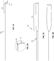
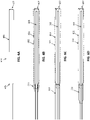
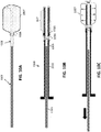
- FIG. 1A shows one variation of a catheter that may form part of the apparatuses described herein.
- the catheter 100 includes a distal end region 103 that includes a distal end 105.
- the distal end region may have an increasing softness (measured by durometer, e.g., shore durometer) except that the very distal tip (distal end 105, including the distal end opening) may be substantially less soft than the region immediately proximate to it.
- the distal tip region of the catheter e.g., the distal most x linear dimensions, where ⁇ is 10 cm, 7 cm, 5 cm, 4 cm, 3 cm, 2 cm, 1 cm, 9 mm, 8 mm, 7 mm, 6 mm, 5 mm, 4 mm, 3 mm
- the very distal end region 107 e.g., measured as distal most z linear dimensions, where z is 1 cm, 9 mm, 8 mm, 7mm, 6 mm, 5 mm, 4 mm, 3 mm, 2 mm, 1mm, 0.8 mm, 0.5mm, 0.3 mm, 0.2mm, etc., and z is always at least three times less than x
- FIG. 1A shows one variation of a catheter of an elongate inversion support that may form part of the apparatuses described herein.
- the elongate inversion support includes a catheter 100 having a distal end region 103 that includes a distal end opening 105.
- the distal end region may have an increasing softness (measured by durometer, e.g., shore durometer) except that the very distal-most end region (distal end 105, including the distal end opening) may be substantially less soft than the region immediately proximate to it.
- the distal tip region of the catheter e.g., the distal most x linear dimensions, where x is 10 cm, 7 cm, 5 cm, 4 cm, 3 cm, 2 cm, 1 cm, 9 mm, 8 mm, 7 mm, 6 mm, 5 mm, 4 mm, 3 mm
- the very distal end region 107 e.g., measured as distal most z linear dimensions, where z is 1 cm, 9 mm, 8 mm, 7mm, 6 mm, 5 mm, 4 mm, 3 mm, 2 mm, 1mm, 0.8 mm, 0.5mm, 0.3 mm, 0.2mm, etc., and z is always at least three times less than x
- the elongate inversion support is an elongate hollow catheter having a column strength that is sufficient to prevent buckling when the catheter is pulled over the distal annulus (distal end opening).
- the elongate inversion support may be configured so that it does not collapse (e.g., buckle) when 500 g or less of of compressive force is applied (e.g., at least about 700 g, 600 g, 500 g, 400 g, 300 g, etc. of compressive force) for neurovascular applications.
- the elongate inversion support may be selected or configured to withstand at least 1500 g of compressive force (e.g., at least about 2000 g, 1900 g, 1800 g, 1700 g, 1600 g, 1500 g, 1400 g, etc. of compressive force).
- any of the apparatuses described herein may include a elongate inversion support that is not a full-length catheter, but may include a portion of a catheter, typically at the distal end, connected to a rod, wire, hypotube, or the like (as will be described in greater detail below in reference to FIGS. 7A-8D ) or may be skived.
- any of the apparatuses and methods described herein may be adapted for use with an elongate inversion support that is not limited to catheters, including elongate inversion supports that include a portion of a catheter, or that include a ring or other structure forming the annulus at the distal end.
- the catheter 100 of the elongate inversion support may be any appropriate type of catheter or portion of a catheter, including microcatheters appropriate for neurovascular use.
- the distal end 105 of the elongate inversion support is adapted so that the tractor may slide or roll and invert over the distal end of the catheter without being caught (binding, jamming) or without substantial friction.
- the distal tip (end) may be curved or radiused 109 as shown in FIG. 1B , particularly on the outer surface (e.g., the transition from outer diameter to inner diameter).
- FIG. 1C shows an example of a flexible tractor 144 coupled to a puller 146.
- the tractor is shown integrated with the puller, forming the assembly.
- the tractor is a tube of material (e.g., wove, knitted, braided, etc.) that is flexible and elongate.
- the tractor is shown extended from the puller in a first configuration. It may be particularly beneficial if the relaxed outer diameter of the flexible tractor in this first configuration has a greater outer diameter than the outer diameter of the catheter of the elongate inversion support into which the tractor will be positioned prior to inverting.
- the flexible and tubular tractor 144 may be sufficiently soft and flexible (e.g., having a low collapse strength) so as to easily roll and fold over the distal aperture of the elongate inversion support.
- the puller 146 may typically be a less-expandable (or non-expandable) structure (tube, puller, etc.).
- the tractor 144 is configured, e.g., by shape-setting (heat setting, etc.), to expand in the relaxed first configuration to a radial diameter that is between 1.1 and 10 times the diameter of the inner diameter of the catheter of the elongate inversion support when unconstrained, as shown in FIG. 1D .
- shape-setting heat setting, etc.
- the expandable tractor may be biased to expand open.
- the tractor may be formed of a mesh, braided, woven, knitted, or sheet of material and is generally adapted to grasp the object to be removed (e.g., blood clot).
- the tractor and puller have two portions, a tractor 144 and a less expandable (or non-expandable) proximal portion comprising the puller 146.
- the puller may be a separate region, such as a wire, catheter or hypotube, which is connected to an end region of the tractor (e.g., a flexible mesh, woven, braided, etc.), e.g., the distal end or near the distal end.
- the inverting region of the tractor, where it rolls and inverts over the distal end opening of the catheter may be referred to as the distal-facing region of the tractor, which may actively grab clot when rolling.
- the flexible tractor of FIG. 1C is shown with the tractor doubled back over itself an over the the distal end of the catheter of the elongate inversion support 101.
- the distal end region is collapsed down, e.g., onto the puller and the elongate inversion support, and may be held collapsed.
- a tractor hold 188 may be used to hold the tractor collapsed down onto the outer diameter of the elongate inversion support.
- the tractor in this second configuration e.g., the portion that is inverted over the distal end of the catheter
- the tractor 144 may be biased so that it has a relaxed expanded configuration in the first configuration (as shown in FIG. 1C ) that is greater than the inner diameter (ID) of the catheter of the elongate inversion support portion of the apparatus and the relaxed expanded configuration of the second configuration (shown in FIG. IF) inverted over the catheter has an OD that is greater than the OD of the catheter.
- the tractor is expandable and may be coupled to the puller.
- the flexible tractor and the puller may comprise the same material but the tractor may be more flexible and/or expandable, or may be connected to a push/pull wire or catheter.
- FIGS. 1G and 1H illustrate the removal of a clot using an apparatus such as the apparatus assembled from the components of FIGS. 1A and IE.
- the apparatus is configured as a thrombectomy apparatus including a catheter of an elongate inversion support 101 and a flexible tractor that extends over the distal end region of the catheter and doubles-over itself at the distal end of the catheter to invert so that the external tractor end region is continuous with an inner less-expandable (in this example, less-expandable includes non-expandable) second distal end region 146 (puller) that extends proximally within the catheter and forms an inner lumen that may pass a guidewire.
- an inner less-expandable in this example, less-expandable includes non-expandable
- second distal end region 146 pulseler
- the pusher/puller member that may be a rod or other member that is continuous with the distal end region of the tractor.
- FIG. 1G the apparatus is shown positioned and deployed within the vessel 160 near a clot 155.
- the clot may be drawn into the catheter by pulling the tractor 140 proximally into the catheter 101, as indicated by the arrow 180 showing pulling of the inner portion of the flexible tractor (e.g., using a handle, not shown) resulting in rolling the tractor over the end opening of the catheter and into the catheter distal end and inverting the expandable distal end region so that it is pulled into the catheter, shown by arrows 182.
- the end of the tractor outside of the catheter may be "loose" relative to the outer wall of the catheter.
- FIG 11 illustrates another example of a tractor assembly 154 including a tractor 144 that is coupled to a puller 156.
- the puller in this example is tapered (having tapering region 161) and may therefore have a different flexibility of the distal end region than the proximal end region.
- the proximal end region may be less flexible than the narrower-diameter distal end region 195 to which the tractor is coupled.
- the assembly includes a radiopaque marker 165.
- the tractor may be attached to the puller by any appropriate means.
- the tractor may be crimped, glued, fused, or otherwise attached to the puller, typically permanently.
- the flexible tractor may not increase the stiffness/flexibility of the catheter, and particularly the distal end region of the catheter too much, to avoid impacting maneuverability, particularly within tortious vessels of the neurovasculature.
- Described herein are flexible tractor tube portions that increase the stiffness of the last y cm (e.g., distal most 20 cm, 18 cm, 15 cm, 12 cm, 10 cm, 9 cm, 8 cm, 7 cm, 6 cm, 5 cm, 4 cm, 3 cm, 2 cm, 1 cm, etc.) of the catheter less than a predetermined percentage (e.g., less than 10%, 12%, 15%, 18%, 20%, 25%, 30%, etc.).
- described herein are flexible tractor tube portions that pass through the catheter and double back over the distal end of the catheter but increase the stiffness of a distal 5 cm of the catheter by less than 15% of the stiffness of the distal 5 cm of the catheter without the flexible tube extending therethrough and doubling back over the distal end of the catheter.
- the tractor in which the tractor is at least partially inverted over the distal end of the catheter so that the tractor extends on the outer surface of the catheter, the tractor may be releasably coupled to the outer diameter of the catheter to allow the apparatus to be inserted through a body, including through tortious vessels in the body, prior to being deployed to remove a clot or other element from the vessel.
- the tractor may be a braided, woven or knit material tube of material that is inverted over the distal end of the catheter; alternatively the tractor may be formed of a sheet of material that include openings therethrough.
- any of the apparatuses described herein may be adapted to prevent premature deployment of the tractor, e.g., by including a tractor hold (e.g., a housing, a lock, a clamp, etc.) or the like to secure the outer end of the tractor against and/or relative to the elongate inversion support.
- a tractor hold may secure the outer end of the tractor against a catheter into which the tractor inverts when pulled proximally by the puller.
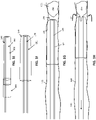
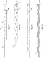
- FIGS. 2A-2C An example of premature deployment is shown in FIGS. 2A-2C .
- the tractor 200 is guided over a guidewire 205 to a clot 255 (alternatively, the apparatus may be delivered without using a guidewire).
- the apparatus includes a tractor 203 that extends over and into a catheter 210.
- the inner end of the tractor is connected to a puller 207 (shown in this example as an inner catheter).
- the outer end 211 of the catheter is loose and is shown slightly expanded over the catheter outer diameter.
- FIG. 2C illustrates the premature deployment compromising the rolling of the tractor 315. Once the tractor is prematurely deployed, moving it back and forth in the vessel to position it may result in the tractor, which may contact the vessel wall when deployed, folding or tangling, as shown in FIG. 2C .
- the apparatuses described herein are configured to prevent premature movement of the tractor on an outside, e.g., outer diameter, of the catheter during catheter access to a target location.
- any of the variations described herein may include a tractor hold that includes a sticky, tacky, gummy, or adhesive material on the tractor or between the tractor and the catheter over a portion of the tractor that is held against the outer diameter of the catheter.
- the apparatus may include a sticky substance, like silicone, impregnated on the end of the tractor that is wrapped over the catheter (e.g., the outer end of the tractor, which may be referred to as the proximal-most most end of tractor).
- the sticky material may impregnated over a small portion of the tractor (e.g., local regions at or near the proximal end and/or discrete regions, or patterns including spots, bands, etc. along the length of the outer portion of the tractor.
- the presence of the sticky regions may prevent premature slipping of the tractor (e.g., braid, woven, etc.) with respect to the catheter.
- a silicone impregnated braid may sit on or over a section of the catheter that is not coated with a hydrophilic coating before the tractor is pulled around distal end opening of the catheter, which may help prevent the tractor from prematurely slipping off or over the catheter.
- a sticky (e.g., tacky, adhesive, gummy, etc.) region may be present on the entire tractor, on just an inside surface of the tractor (e.g., the surface that faces the catheter when applied over the outer diameter of the catheter), on both inner and outer surface of the tractor, and/or in discrete locations (including patterns) of the portion of the tractor outside of the catheter.
- the apparatus may include a plurality of regions of sticky material arranged over the length of the proximal end of the tractor.
- the sticky material is arranged in a pattern.
- the material applied may be referred to as sticky with respect to the catheter (e.g., causing temporary and/or releasable attachment between the catheter and the tractor).
- the sticky material may be coated or applied to the outer diameter of the catheter.
- the pattern of sticky material locations on the tractor (and/or catheter) may be arranged in multiple, non-contiguous locations along the length or the tractor. Patterns may include stripes, spirals, rings, spots, etc.
- the tractor may be temporarily secured to the outside of the catheter through other methods to provide a temporary attachment of the tractor to the catheter outer diameter (OD).
- a temporary attachment may be presented between the tractor and the catheter OD such that, when axial tension if applied to the tractor, e.g., by the user pulling the tractor to pull the tractor around catheter tip, the temporary attachment (e.g., a temporary bond, temporary securement, etc.) between the tractor and the catheter OD may be released, allowing the braid to slide relative to the catheter.
- temporary attachments between the tractor and the OD of catheter may include: hydrophilic coatings on the tractor and/or catheter, and/or spot (including micro-spot) boding between the catheter and the tractor.
- a hydrophilic surface on the tractor (e.g., inner face of the tractor) and/or catheter OD may be applied as a coating.
- the tractor may be pre-assembled onto the catheter and a hydrophilic/hydrophobic surface may provide a temporary attachment between the catheter and the tractor.
- a layer of hydrophilic coating (or two adjacent layers) may secure the tractor to the catheter OD, and may help the apparatus track through a body vessel/lumen to the target location, after which the tractor may be deployed by pulling to separate the surfaces of the tractor and catheter OD, and to allow the tractor to roll over the distal end opening freely so that it may engage with a clot and draw it into the apparatus.
- a hydrophilic coating may be separately applied to the tractor and/or the catheter.
- the catheter OD and tractor may be separately coated with a hydrophilic coating and then assembled.
- the coating on both subassemblies e.g., tractor and catheter
- the user may pull the tractor proximally (by pulling on the puller attached to the inner end of the tractor) which may slide the tractor with respect to the catheter OD, disengaging the tractor hold.
- the tractor hold can be formed by spot- or selectively bonding the tractor to the catheter OD.
- a spot or micro-bond may be adequate to prevent premature sliding of the tractor relative to the catheter OD during catheter access.
- a spot bond or a plurality of micro-bonds can be created, e.g., by heat bonding (melting) or applying adhesive to attach the tractor to the catheter OD.
- the micro bonds can be placed circumferentially at several locations along the length of the braid, continuously along the braid/catheter contact length or in any other pattern, as discussed above.
- FIG. 4A illustrates an example of a thermoplastic polyurethane (TPU) 404 that may be used to temporarily secure the tractor 406 to the outer diameter of the catheter; once in position, the distal end of the catheter (internal to the catheter) may be pulled proximally to break the material (in this example, pellathane) and release the tractor so that it may be rolled distally over the catheter to draw a clot into the catheter.
- the frangible (e.g., breakable) material is coated over a region on the catheter and/or tractor (shown here as a braided tractor) that does not include a hydrophilic coating).
- the frangible material may be applied over a region that is masked (uncoated) from hydrophilic coating.
- FIGS. 4B and 4C examples of mechanical thrombectomy apparatuses 400, 400' are shown, each having an outer catheter 409, and a tractor that extends over the distal end region of the catheter, and inverts over the distal end opening (annulus 411) of the catheter, and into the catheter where it connects to a puller 407.
- the tractor is releasably adhered to the outer diameter of the catheter by a sticky (e.g., hydrophilic) region 414 that engages the outer end of the tractor to a region on the outer diameter of the catheter.
- an initial deployment force threshold (e.g., between 0.5 N and 50 N) may be required.
- the force required to continue rolling may be substantially (e.g., the deployment force threshold may be 1.1 ⁇ , 1.2 ⁇ , 1.5 ⁇ , 1.7 ⁇ , 2 ⁇ , 3 ⁇ , 4 ⁇ , 5 ⁇ , 10 ⁇ , or more the force required to roll the apparatus).
- the apparatus may include a plurality of spot attachments 424 at the outer end of the tractor.
- there spots may be an adhesive attached into (e.g., into the mesh, etc.) of the tractor, or between the tractor and the outer diameter of the catheter.
- the tractor may be held slightly in tension over the distal end region of the catheter, preventing the tractor from deploying and expanding, including expanding at the distal tip region (forming the trumpet-shaped opening such as shown in FIGS. 2A-2B ).
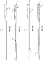
- any of the apparatuses described herein may include a tractor hold that is configured as a housing or garage for holding the outer end of the tractor, as shown in FIGS. 3A-3C and FIGS. 5A-5C .
- the tractor hold extends only partially down the catheter, which may prevent the hold from increasing the flexibility and maneuverability of the apparatus in the lumen.
- FIGS. 3A-3C illustrate the exemplary method of use of a variation of a mechanical thrombectomy apparatus 300 including a tractor hold 303.
- the tractor hold is positioned over the catheter, as shown in FIG. 3A , and holds the outer end of the tractor 305 against the outer diameter of the catheter 307.
- the tractor is connected to the puller 309.
- the tractor hold may be attached to the catheter (e.g., at a proximal end of the hold) or it may be applied over the catheter (e.g., shrink-wrapped over the catheter and the outer end of the tractor.
- the apparatus 300 may be guided over a guidewire 319, as shown, or it may be directed to the clot 355 within the vessel 360 without the use of a guidewire.
- a force greater than a deployment threshold force e.g., the force required to pull the tractor out of the tractor hold 303, leaving the tractor hold behind, and allowing the tractor to roll 382 over the distal end opening of the catheter, as illustrated in FIG. 3C .
- the apparatus may be advanced distally while pulling the inner end of the tractor proximally with the puller to invert and roll the tractor into the catheter. The tractor may then grab a clot and pull it into the catheter, as shown.
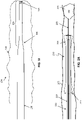
- the apparatus 500 includes a tractor 503 coupled to a puller 507 at an inner end that is within a catheter 509.
- the outer end 504 of the tractor is pinned against the outer diameter of the catheter by a tractor hold 501 configured as a garage or housing.
- the housing may hold the end of the tractor lightly or it may secure it against the catheter more tightly, depending on the desired deployment threshold.
- the tractor hold is secured to the outer diameter of the catheter by a weld or welds 505.
- the tractor hold is secured by either being shrunk-fit to the outer diameter at the proximal end 515, or by an adhesive or glue 525, respectively.
- the tractor hold extends only slightly down the length of the catheter, e.g., a few cm (e.g., less than 10 cm, less than 9 cm, less than 8 cm, less than 7 cm, less than 6 cm, less than 5 cm, less than 4 cm, less than 3 cm, etc.).
- the elongate inversion support may have a different outer diameter along its axial (longitudinal) length.
- the catheter shown in FIG. 1A has a uniform diameter along its length
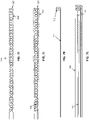
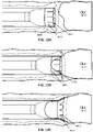
- other apparatuses may include a catheter having a larger diameter at the distal end region than at more proximal regions, as shown in FIGS. 6A-8C .
- the elongate inversion support is a catheter having a larger outer diameter at the distal end than at the proximal end.
- the transition between the two regions is a step 605.
- the annular region (distal end opening 607) therefore has the same, larger, outer diameter as the distal end region.
- FIG. 6B-6C illustrates examples in which a tractor is held over the outer diameter and may be secured by a tractor hold.
- the tractor is configured to contract down onto the tractor, simply having the transition, and particularly a rapid (including step) transition between a region of larger diameter and a region of smaller diameter, as shown in FIG. 6A , may help secure the tractor over the catheter.
- FIG. 6B the same catheter shown in FIG. 6A has had a tractor 603 attached so that it extends along the distal outer diameter region, inverts over the distal end opening 607, and into the catheter inner lumen, where it is connected to or integral with a puller 609.
- the outer end of the tractor is held in place with a tractor hold 613; in this example, the tractor hold 613 is one or more arms that hold the tractor against the smaller inner diameter immediately adjacent to the step up to the larger diameter region of the catheter.
- the tractor hold is a narrower catheter 623 that extends proximally; the tractor is held between the distal opening of the tractor hold and the step up to the larger diameter catheter 601.
- the outer surfaces of the tractor hold and the catheter 601 may be flush, e.g., having the same height.
- the tractor hold extends proximally far enough (e.g., to or beyond the end of the catheter) it may be actively disengaged, reducing or eliminating the deployment threshold force.
- FIG. 6D shows another example of a tractor lock 633, similar to that shown in FIG. 6C , only extending partially proximally down the catheter.
- the tractor hold may be fixed to the outer diameter or it may be movable (e.g., slideable) relative to the outer diameter of the catheter.
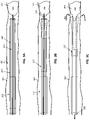
- FIGS. 7A-7L illustrate different variations of catheters that may be used as part of any of the apparatuses described herein.
- FIG. 7A shows an example of a catheter 700 having a larger-diameter distal end region that also includes a plurality of openings, slots, holes, windows, slits, etc. 709. These openings may provide for delivery of fluid (including drugs) to the site of use, and/or removal of material, e.g., the application of vacuum through the apparatus, particularly useful when used with an intermediate catheter into which the apparatus (e.g., an elongate inversion support, a puller and tractor) is inserted, as will be described in greater detail below.
- FIG. 7B shows the apparatus of FIG. 7A with an attached puller and tractor.
- FIGS. 7C and 7D illustrate another variation of a catheter that may be used as part of any of the apparatuses described herein, including, as here, catheters that have a plurality of cut-out regions.
- FIGS. 7E and 7F show an example including a catheter having a large proximal skive region, leaving the majority of the outer diameter much smaller than at the distal end region, as shown.
- the distal end of the catheter may include openings, slots, cut-out regions, etc. 725.
- FIG. 7F shows the catheter of FIG. 7E with a tractor 714 coupled on an inner end to a puller 713. The puller is still pulled within the lumen of the catheter.
- FIGS. 7C and 7D illustrate another variation of a catheter that may be used as part of any of the apparatuses described herein, including, as here, catheters that have a plurality of cut-out regions.
- FIGS. 7E and 7F show an example including a catheter having a large proximal skive region
- the elongate inversion support includes a distal portion formed of a catheter having cut-out regions 725 that is coupled to a rod, pole, wire or (as shown) a hypotube.
- This hypotube may be used as a guidewire lumen and/or as a channel for a stiffening or support member that may, once the device is positioned, enhance the column strength to allow pulling of the tractor proximally when inverting the tractor to roll.
- FIGS. 71 and 7J illustrate an example of a catheter ( FIG. 71 ) and an apparatus including the catheter (7J) in which the sides of the catheter have been slotted, which may provide enhanced flexibility while maintaining column strength.
- An apparatus including the catheter of FIG. 71 is shown in FIG. 7J , also including a tractor and puller.
- FIG. 7K is an example of an elongate inversion support in which the distal end is a cylinder 716, formed, for example, from a very small portion of a catheter.
- the distal end opening (annulus 707) may be used to invert the tractor, as shown in FIG. 7L .
- the elongate shaft 717 of the elongate inversion support may be a rod, tube, wire, etc. as described above.
- An additional outer catheter 726 may be included in any of these apparatuses, as shown in the exemplary apparatus shown in FIG. 7L , which includes the elongate inversion support of FIG. 7K .
- FIGS. 8A-8D also illustrate another example of an elongate inversion support having a distal annulus or aperture 743, shown in this example a ring (e.g., toroid ring) bonded to a hypotube 746 (which may alternatively be a rod, wire, small-diameter catheter, etc.); as mentioned above, a stiffening member may be inserted into the elongate body of the elongate inversion support prior to or during pulling of the tractor proximally through the distal annulus.
- FIG.8B shows a similar variations of the elongate inversion support of FIG.
- FIG. 8C is an apparatus similar to that shown in FIG. 8C with the addition of an outer catheter 809.
- the tractor hold and distal end region of the catheter to which it is applied over may be configured as (or may include) a releasable lock, in addition to or instead of the tractor holds described above (e.g., a sticky materials, frangible release, housing, etc.).
- the catheter may include a tractor hold comprising a friction lock (e.g., bump, protrusion, enlarged diameter, region, O-ring, etc.) on the outer diameter of the catheter that engages with a locking region (e.g., construction, inward-pointing bump, sticky coating, etc.) on the outer (e.g., proximal) end region of the tractor.
- a friction lock e.g., bump, protrusion, enlarged diameter, region, O-ring, etc.
- a locking region e.g., construction, inward-pointing bump, sticky coating, etc.
- the locking region on the outer end portion of the tractor may be proximally beyond the locking region (e.g., friction bump) on the catheter, so that the catheter locking region may be initially held beneath the tractor.
- force e.g., deployment force applied by the user
- the force may overcome the locking engagement between the tractor locking region (e.g., constriction, inwardly-facing protrusion, etc.) and the locking catheter locking region (e.g., friction bump, radial enlargement, O-ring, etc.) and the tractor may be released roll distally over the catheter. See FIGS. 10A-10C for an example of this arrangement.
- the tractor 1007 includes a tractor lock 1006 at the outer end of the tractor.
- FIG. 10A shows just the tractor and puller 1003.
- the mechanical thrombectomy apparatus 1000 shown in FIG. 10B also includes a catheter 1011, and the catheter includes a tractor hold 1009. The tractor hold engages with the tractor lock; in FIG. 10A-10C , the tractor 1007 includes a tractor lock 1006 at the outer end of the tractor.
- FIG. 10A shows just the tractor and puller 1003.
- the mechanical thrombectomy apparatus 1000 shown in FIG. 10B also includes a catheter 1011, and the catheter includes a tractor hold 1009. The tractor hold engages with the tractor lock; in FIG.
- the tractor hold is a protrusion that holds the tractor lock on the tractor on a proximal side of the tractor hold, until sufficient force is applied above the deployment threshold to deploy the tractor by pulling the tractor lock distally over the tractor hold, allowing the tractor 1007 to deploy and/or expanded, and be rolled over the distal end opening of the catheter, to capture a clot.
- the tractor region may be held in tension, although tension is not necessary.
- a second outer cover or catheter may be used, or may be absent.
- the puller may extend more distally than the tractor in the apparatus.
- a pre-assembled apparatus having the distal end of a tractor puller (e.g., catheter, hypotube, wire, etc.) that extends more distally beyond the catheter(s) or the rest of the apparatus may be used to help capture the clot.
- a tractor puller e.g., catheter, hypotube, wire, etc.
- any of these variations may include the use of a vacuum, e.g., for aspirating the clot.
- the vacuum may be applied through the puller. It may be easier to grab onto a clot when using aspiration to initiate the grabbing.
- FIG. 9A illustrates a mechanical thrombectomy apparatus according to the invention similar to that described above.
- the tractor 903 is connected to a puller 905 and the tractor extends along the outer diameter 901 of the catheter.
- the tractor may be infused, bonded or laminated with a stiffening element in part to make it less likely that the tractor collapses in diameter when the dozer catheter is pulled and allows for vacuum applied to the applied to the proximal end of the tractor puller 905 to exert force/vacuum on the clot via the distal end of the assembly, as shown in FIGS. 9B and 9C .
- FIG. 9B the tractor is coupled to a portion of the tractor puller 905 that is proximal 921 to a distal end of the puller.
- the tip may extend past the distal end of the catheter, prior to inverting the tractor.
- FIG. 9B also shows an (optional) tractor hold 917
- the apparatus includes a stop element attached at or near the distal end of the puller 905.
- a sliding ring 911 on the tractor may be used to allow the puller to slide distally without pulling on the tractor; only when the puller is withdrawn proximally far enough that the stop 909 engages with the sliding ring 911 does the puller pull the tractor proximally, and invert the tractor over the distal end opening of the catheter, rolling the tractor an pulling in any clot material, which may be aided by the application of vacuum 914 through the puller.
- this arrangement may allow the user to extend the tractor puller distally at lengths beyond the distal end of the catheter without pulling the tractor distally.
- the apparatus may be coupled to a valve 923 for connection to a vacuum source 914.
- the vacuum may be connected to the elongate inversion support (e.g., catheter) and/or to the puller, as shown in FIGS. 9A-9C .
- any of the apparatus variations described herein may include a lubricous coatings such as hydrophilic coatings applied on the OD &/or ID of the tractor, on any and all sections, and/or on the outer or inner diameter of the elongate inversion support (e.g., catheter).
- a lubricous coatings such as hydrophilic coatings applied on the OD &/or ID of the tractor, on any and all sections, and/or on the outer or inner diameter of the elongate inversion support (e.g., catheter).
- the apparatuses described herein may allow delivery of a guidewire and/or a smaller catheter through the outer catheter and tractor, which may be useful for both guidewire operation (for clot access) and also for applying optional vacuum.
- the tractors described herein may have minimal to no collapsing when they are inverted inside the outer catheter when under axial tension, which may prevent jamming on the catheter distal tip and may reduce the amount and/or volume of clot that can be extracted.
- any of the tractors described herein may have adequate coarseness to grab the clot, yet still roll smoothly around the distal annulus.
- the tractor does not adversely affect catheter tracking, as it may be extremely flexible and slippery.
- the pre-loaded tractors described herein may not slide with respect to the OD of catheter during vessel access.
- the tractor may only slide on the OD of catheter when the user pulls the tractor puller.
- the user may advance the elongate inversion support (e.g., catheter) forward while holding the tractor puller fixed, thereby enveloping clot in place rather than pulling clot to catheter.
- the tractor may be biased (e.g., heat-shaped) to a preferred configuration to help grab clot effectively and roll nicely around the catheter tip.
- the distal end of the catheter (tip) may be stiffer than the catheter section just proximal to the tip (to allow rolling of dozer around tip).
- the tip may include a lubricious coating.
- the catheter tip may have a radius of > 0.00025", > 0.00035", > 0.0004", > 0.0004", > 0.00025", or ⁇ 0.0005" to allow rolling of tractor more easily.
- the distal region (e.g., distal 5 cm, 10 cm, etc.) of the catheter allows for tracking through 1/8" diameter radius and also has a limited axial compress to ⁇ 10% of the distal catheter length during axial compression loads of, e.g., 100g, 200g, and 300g, etc. when pulling in the dozer and grabbing clot.
- any of these apparatuses may allow for the delivery of guidewire and/or smaller catheter through aspiration catheter.
- the tractor may be configured to have a Poisson ratio ⁇ 1.5 (e.g., ⁇ 1.2, ⁇ 1.1, etc.) when under tension (this helps prevent the tractor from jamming on catheter tip).
- the tractor and/or catheter may be radiopaque.
- a band or region may be radiopaque.
- the entire tractor may be radiopaque, e.g., NiTi wire filled with PT or Tantalum (DFT wire) may be used to form the tractor.
- DFT wire Tantalum
- the proximal and/or distal end of the tractor may have radiopaque markers.
- the apparatuses described herein may be used to remove materials such as clots, including to prevent or treat stroke.
- the apparatuses described herein may be used to track up through the siphon of the carotid artery, which is typically highly tortious. When pulled, the tractor may roll around the catheter distal end without locking up, while still grabbing clot.
- any of these apparatuses may also work in combination with a vacuum. The use of a vacuum may be unnecessary, but may be beneficial, particularly when initially engaging the clot with the tractor region and/or the distal end of the catheter.
- any of the apparatuses described herein may also be configured to grab a clot in a large variety of vessels, including those ranging from 1.5 mm to 3.5 mm, even when the catheter has approximately the same outer diameter as the inner diameter of the vessel, or where the catheter is otherwise corked in the vessel.
- any of the apparatuses described herein may be adapted for use with a vacuum to apply suction (e.g. aspiration) to assist in clot removal.
- suction e.g. aspiration
- the device may be used without the use of aspiration, in some instances clot removal may be aided by the use of the mechanical atherectomy apparatuses described herein.
- traditional techniques for removing a clot using aspiration e.g., using a simple flexible catheter, commonly referred to as an intermediate catheter
- use of aspiration alone often results in clogging of the intermediate (aspiration) catheter and may therefore have trouble removing the entire clot, particularly in the tortious vessels.
- any of the apparatuses described herein may be used with an intermediate catheter, and may be adapted for use with vacuum clot removal technique, including being adapted to permit vacuum to be applied while the apparatus is within the lumen of the intermediate catheter, so that aspiration may still be applied from the distal end of the intermediate catheter and/or the apparatus, as well as permitting aspiration to be applied while the apparatus is extended distally from the intermediate catheter.
- the applied vacuum may aid in initially gasping or grabbing the thrombus.
- the vacuum may be applied from the distal end of the apparatus and/or of an intermediate or outer catheter or sleeve that is used with the apparatuses (e.g., elongate inversion support and inverting tractor).
- FIGS. 7A-8D are examples of elongate inversion supports that may be used in any of the apparatuses described; these elongate inversion supports may be particularly well suited to applying aspiration from the intermediate catheter.
- FIG. 11A shows an example of a configuration in which an outer/intermediate catheter or sleeve that is highly flexible may be maneuvered, for example with a guidewire, to a distal end of the device.
- the intermediate catheter may be maneuvered near, or adjacent to, the thrombus.
- imaging such as fluoroscopy, contrast imaging, etc.
- the guidewire Once in positioned, the guidewire may be removed or left in place, and the apparatus including the elongate inversion support and inverting tractor may be extended within the intermediate catheter/sleeve.
- the intermediate catheter 4104 is shown positioned within the vessel 4109 distally.
- the vessel maybe highly tortious and branching, although for convenience it is shown as straight in the figures.
- the apparatus 4100 is extended distally through the intermediate catheter, and extends out of the distal opening of the intermediate catheter to grab the clot 4111, as shown.
- the puller 4105 may thus be drawn proximally (to the left in the figure) to pull the tractor 4103 from over the catheter portion of the elongate inversion support 4113, so that it inverts and rolls into the lumen of the elongate inversion support, capturing and drawing the clot in with it.
- the clot may be compressed.
- this configuration may be referred to as a vessel cleaner.
- the clot may be pulled by a vacuum applied from one or both of the intermediate catheter 4121 and/or the elongate inversion support 4123. Vacuum may be applied, e.g., within the intermediate catheter, before the apparatus is positioned distally (or even within the intermediate catheter at all) or after it has been extended distally from the intermediate catheter.
- This configuration shown in FIG. 11A may introduce the tractor through outer catheter to the face of clot.
- the mechanical thrombectomy apparatus may be extended distally from the intermediate catheter either by pushing it out distally and/or by pulling back the intermediate catheter to deploy all or part of the tractor into vessel, as shown. If vacuum is applied through the catheter, the catheter forming the elongate inversion support may be jacketed or sealed to allow aspiration through this catheter.
- outer and/or inner and/or puller may be pulled proximally relative to the the elongate inversion support to pull the clot.
- the intermediate catheter may then be advanced distally and/or the mechanical thrombectomy apparatus may be withdrawn proximally to remove the apparatus once the clot has been removed. Thereafter an angiogram may be taken to confirm that the clot has been removed.
- a clot may be removed using the intermediate catheter to draw a vacuum with the mechanical thrombectomy apparatus within the lumen (e.g., near the distal end, but not extending fully from the distal end) of the intermediate catheter.
- the intermediate catheter may be inserted into the vessel (e.g., using a guidewire) so that the distal end is positioned near the clot.
- Suction may be used to draw the clot into the intermediate catheter either before the mechanical thrombectomy device is inserted or after it has been inserted.
- the elongate inversion support 4113' is particularly well suited for use with a vacuum applied through the intermediate catheter 4104 surrounding the apparatus.
- the elongate inversion support 4113' include a distal catheter region 4125 that extends just a few cm from the distal end opening in which the clot is drawn.
- the elongate inversion support then tapers down to an elongate support, which may be formed by a wire, hypotube or skived region. This configuration may prevent the catheter from blocking the lumen of the intermediate catheter and and therefore increasing the resistance of the vacuum before it can reach the open distal end and apply suction to drawn the clot.
- the outer diameter of the catheter portion of the elongate inversion support may be sized to allow more of the vacuum to pass.
- the apparatus may be sized such that there is at least about 0.002 inches or greater (e.g., 0.003, 0.004, 0.005, 0.006, etc., inches) between the outer diameter of the catheter and the inner diameter of the intermediate catheter ("outer catheter"). This may also permit unimpeded rolling of the tractor over the distal end opening of the elongate inversion support.
- the exemplary method not forming part of the invention of removing clot may include pulling at least the tip of a clot into the intermediate catheter through the use of a vacuum 4121.
- the clot may clog within the intermediate catheter; the mechanical thrombectomy apparatuses described herein may be used to remove the clot from within the intermediate catheter.
- the mechanical thrombectomy apparatus may be inserted (or it may be preloaded in intermediate catheter as mentioned) and the tractor puller 4105 may be pulled to pull the clot out of the intermediate catheter and the vessel, compress and/or macerate it and pull it into the apparatus and therefore the intermediate catheter, where it can be withdrawn proximally, e.g., by removing the mechanical thrombectomy apparatus.
- an angiogram may be taken through intermediate catheter (e.g., leaving it in place in case the mechanical thrombectomy apparatus needs to be re-inserted and used to remove more clot) to confirm clot has been removed.
- a full catheter such as shown in FIG. 11A may block or prevent the vacuum from reaching the distal end of the intermediate vessel. Therefore it may be beneficial to adapt the mechanical thrombectomy apparatus so that it can be used with vacuum within an intermediate catheter or sleeve, as shown in FIG. 11B . This may be achieved as mentioned above, by minimizing the larger-diameter catheter portion of the elongate inversion support forming the distal end opening over which the tractor inverts.
- FIGS. 7A-8D in FIG.
- the elongate inversion support 700 has a distal catheter portion 701 having a larger diameter than the more proximal region 703, and also includes a plurality of openings, holes, gaps, cut-out regions, slots, etc. 709 that may allow the flow of vacuum through the elongate inversion support more easily.
- the elongate inversion support shown also includes a distal end 707 into which a tractor 711 inverts, as shown in FIG. 7B .
- the elongate inversion support is shown transparent so that the puller 713 and tractor within the elongate inversion support is visible.
- the entire length of the elongate inversion support includes a plurality of cut-out regions 713 which may increase the ability to allow the flow of a vacuum or other fluid within the apparatus, but may still allow the elongate inversion support to provide column strength to resist collapsing up to at least 500 g of compressive longitudinal force applied by, e.g., pulling on the tractor.
- the elongate inversion support of FIGS. 7E and 7F show a skived catheter that also includes openings 709 along its length. The puller and tractor 412 are shown within the elongate inversion support in FIG. 7F.
- FIGS. 71 and 7J illustrate an example in which rather than a skived portion of the catheter, the distal catheter region of the elongate inversion support is formed by a wire, bar, tube, 721 etc., that is attached to the catheter at the distal end.
- the catheter may also optionally include openings 709.
- the elongate inversion support of FIGS. 71 and 7J includes openings 709' along all or much of its length (particularly near the distal end region) as shown.
- the variation of the elongate inversion support shown in FIG. 7K includes a minimal catheter portion (cylinder 716) that is connected to a wire, bar, tube, hypotube, skived region, etc. 717.
- FIGS. 8A-8D illustrate the operation of a similar minimal elongate inversion support 800.
- the apparatus includes a distal aperture 743 bonded securely to a wire, bar, tube, hypotube, skived region, etc. 746 forming an elongate support.
- the elongate support may be hollow (e.g., may include a lumen for a guidewire) or solid.
- the elongate support may also include one or more additional support guides 750 as shown in FIG. 8B . These supports may help contain the puller and/or tractor within the elongate inversion support. Any of the elongate inversion supports described herein may include additional support guides.
- FIG. 8B is shown with a tractor 711 and puller 713 in FIG. 8C .
- this variation may be particularly well suited for use with an intermediate (e.g., "outer") catheter, sleeve, or the like 809, as shown in FIG. 8D .
- an intermediate catheter e.g., "outer” catheter, sleeve, or the like 809, as shown in FIG. 8D .
- any of the mechanical thrombectomy apparatuses described herein may include an elongate inversion support having a distal end that is expandable from a smaller diameter aperture (e.g., distal end opening) to a larger-diameter aperture. This expansion may be performed by pulling the clot within the catheter.
- FIGS. 12A-12C illustrates the operation of an example of an elongate inversion support configured as a catheter having an expandable distal end.
- the catheter distal end 4401 may include slots or slits 4403 formed or cut, e.g., by laser-cutting, in the distal end of the catheter of the elongate inversion support.
- the apparatus may be operated as described above, positioning near (e.g., against or adjacent to) a clot, and pulling proximally on the puller to draw the tractor 4405 into the catheter, as shown in FIG. 12B .
- the apparatuses described herein may generally compress a clot greatly, compression may be made easier and/or more efficient by providing a more gradual decrease in radial diameter.
- FIG. 12B when the tractor is rolled over the distal end opening and inverted, the clot maybe drawn in along with the tractor. As the large clot 4413 is brought into the distal end opening, the distal end opening may expand and open along the slots or slits 4403, as shown in FIG. 12C , so that the distal end opening flares out.
- an elastic sleeve, gasket, ring or cover may be included at least partially covering the distal end to prevent the edge from catching the tractor.
- an elastic or stretchable layer may cover the cut distal end so that the distal end may be opened to form an outward flare.
- FIG. 12C the outward-flared distal end is shown forming a funnel-shape into which the clot may be pulled. This funnel-shaped opening may help compress the clot so that it may be drawn into the mechanical thrombectomy apparatus.
- the elongate inversion support may be configured to have, or to assume, a funnel-shape at the distal-facing end.
- the distal-facing end may always have a funnel-shaped mouth at the distal end opening, or the distal end opening may be configured to assume a funnel shape, as shown in FIGS. 12A-12C .
- the distal end of the elongate inversion support is configured to be elastic in a radial directly, but maintain stiffness along the proximal-to-distal axis (in compressive load).
- the distal end of the elongate inversion support may be configured with strands or rods extending in the proximal-to-distal axis that have a high compressive load strength, but which may separate from each other to enlarge the distal end opening; for example they may be connected by rings in which more distal rings are more elastic/stretchable than more proximal rings.
Claims (5)
- Appareil de thrombectomie mécanique pour l'élimination d'un caillot dans un vaisseau, l'appareil comprenant :- un cathéter (901) présentant une extrémité proximale et une extrémité distale ainsi qu'une ouverture d'extrémité distale ;dans lequel l'appareil de thrombectomie comprend en outre :- un tracteur (903) comprenant un tube flexible s'étendant à l'intérieur du cathéter (901), s'inversant sur l'ouverture d'extrémité distale du cathéter (901) et s'étendant sur l'extrémité distale du cathéter (901), le tracteur (903) étant configuré pour s'inverser en roulant sur l'ouverture d'extrémité distale du cathéter (901) lorsqu'une première extrémité du tracteur (903) est tirée de façon proximale à l'intérieur du cathéter (901) ; et- un extracteur (905) présentant une extrémité proximale et une extrémité distale, la première extrémité du tracteur (903) étant accouplée à l'extracteur (905) au niveau d'une région (921) proximale par rapport à l'extrémité distale de l'extracteur (905), l'extracteur (905) s'étendant en outre à l'intérieur du cathéter (901) jusqu'à l'extrémité proximale du cathéter (901) ;dans lequel l'appareil de thrombectomie comprend en outre :- une lumière de fil de guidage s'étendant à travers le cathéter (901), l'extracteur (905) et le tracteur (903), et étant configurée pour laisser passer un fil de guidage, une distance de deux mm ou plus étant prévue entre l'extrémité distale de l'extracteur (905) et la région (921) de l'extracteur (905) à laquelle la première extrémité du tracteur (903) est accouplée.
- Appareil selon la revendication 1, comprenant en outre une butée (909) entre l'extrémité distale de l'extracteur (905) et l'ouverture d'extrémité distale.
- Appareil selon la revendication 2, dans lequel la butée (909) est disposée sur l'extracteur (905) entre l'extrémité distale de l'extracteur (905) et la première extrémité du tracteur (903), et dans lequel la première extrémité du tracteur (903) est accouplée à une bague coulissante (911) configurée pour coulisser sur l'extracteur (905) jusqu'à son engagement avec la butée (909).
- Appareil selon la revendication 1, dans lequel l'extrémité proximale de l'extracteur (905) est configurée pour être accouplée à une source de vide (914).
- Appareil selon la revendication 1, dans lequel l'extrémité proximale de l'extracteur (905) comprend une soupape Tuohy-Borst ou une soupape hémostatique rotative (RHV).
Priority Applications (1)
| Application Number | Priority Date | Filing Date | Title |
|---|---|---|---|
| EP22179701.2A EP4091557A1 (fr) | 2016-04-25 | 2017-04-25 | Appareils tracteurs d'inversion préchargés pour la thrombectomie et procédés |
Applications Claiming Priority (4)
| Application Number | Priority Date | Filing Date | Title |
|---|---|---|---|
| US201662327024P | 2016-04-25 | 2016-04-25 | |
| US201662345152P | 2016-06-03 | 2016-06-03 | |
| US201662357677P | 2016-07-01 | 2016-07-01 | |
| PCT/US2017/029366 WO2017189550A1 (fr) | 2016-04-25 | 2017-04-25 | Appareils et procédés de thrombectomie à tracteur à inversion préchargé |
Related Child Applications (1)
| Application Number | Title | Priority Date | Filing Date |
|---|---|---|---|
| EP22179701.2A Division EP4091557A1 (fr) | 2016-04-25 | 2017-04-25 | Appareils tracteurs d'inversion préchargés pour la thrombectomie et procédés |
Publications (2)
| Publication Number | Publication Date |
|---|---|
| EP3448277A1 EP3448277A1 (fr) | 2019-03-06 |
| EP3448277B1 true EP3448277B1 (fr) | 2022-07-06 |
Family
ID=58664898
Family Applications (3)
| Application Number | Title | Priority Date | Filing Date |
|---|---|---|---|
| EP17721036.6A Active EP3448276B1 (fr) | 2016-04-25 | 2017-04-25 | Appareils de thrombectomie mécanique capteurs de caillots |
| EP17722277.5A Active EP3448277B1 (fr) | 2016-04-25 | 2017-04-25 | Appareils de thrombectomie à tracteur à inversion préchargé |
| EP22179701.2A Pending EP4091557A1 (fr) | 2016-04-25 | 2017-04-25 | Appareils tracteurs d'inversion préchargés pour la thrombectomie et procédés |
Family Applications Before (1)
| Application Number | Title | Priority Date | Filing Date |
|---|---|---|---|
| EP17721036.6A Active EP3448276B1 (fr) | 2016-04-25 | 2017-04-25 | Appareils de thrombectomie mécanique capteurs de caillots |
Family Applications After (1)
| Application Number | Title | Priority Date | Filing Date |
|---|---|---|---|
| EP22179701.2A Pending EP4091557A1 (fr) | 2016-04-25 | 2017-04-25 | Appareils tracteurs d'inversion préchargés pour la thrombectomie et procédés |
Country Status (6)
| Country | Link |
|---|---|
| US (6) | US9962178B2 (fr) |
| EP (3) | EP3448276B1 (fr) |
| JP (3) | JP6873227B2 (fr) |
| CN (3) | CN113576607A (fr) |
| ES (2) | ES2792100T3 (fr) |
| WO (2) | WO2017189615A1 (fr) |
Families Citing this family (170)
| Publication number | Priority date | Publication date | Assignee | Title |
|---|---|---|---|---|
| US7686825B2 (en) | 2004-03-25 | 2010-03-30 | Hauser David L | Vascular filter device |
| KR101334502B1 (ko) | 2005-10-19 | 2013-12-05 | 펄사 배스큘러, 아이엔씨. | 내강과 조직 결함을 치료하고 혈관내 결찰을 위한 장치 및 시스템 |
| US10517617B2 (en) | 2007-12-20 | 2019-12-31 | Angiodynamics, Inc. | Systems and methods for removing undesirable material within a circulatory system utilizing a balloon catheter |
| US11589880B2 (en) | 2007-12-20 | 2023-02-28 | Angiodynamics, Inc. | System and methods for removing undesirable material within a circulatory system utilizing during a surgical procedure |
| US8070694B2 (en) | 2008-07-14 | 2011-12-06 | Medtronic Vascular, Inc. | Fiber based medical devices and aspiration catheters |
| US9402707B2 (en) | 2008-07-22 | 2016-08-02 | Neuravi Limited | Clot capture systems and associated methods |
| CN102202585B (zh) | 2008-09-05 | 2014-04-02 | 帕尔萨脉管公司 | 用于支撑或闭塞生理开口或腔的系统和方法 |
| ES2683943T3 (es) | 2010-10-22 | 2018-09-28 | Neuravi Limited | Sistema de captura y extirpación de coágulos |
| US11259824B2 (en) | 2011-03-09 | 2022-03-01 | Neuravi Limited | Clot retrieval device for removing occlusive clot from a blood vessel |
| ES2871050T3 (es) | 2011-03-09 | 2021-10-28 | Neuravi Ltd | Un dispositivo de recuperación de coágulos para eliminar el coágulo oclusivo de un vaso de sangre |
| KR102018035B1 (ko) | 2011-06-03 | 2019-09-05 | 펄사 배스큘라, 아이엔씨. | 추가적인 고정 메커니즘을 가진 동맥류 장치 및 이와 관련된 시스템과 방법 |
| US9119625B2 (en) | 2011-10-05 | 2015-09-01 | Pulsar Vascular, Inc. | Devices, systems and methods for enclosing an anatomical opening |
| US8784434B2 (en) | 2012-11-20 | 2014-07-22 | Inceptus Medical, Inc. | Methods and apparatus for treating embolism |
| US10603157B2 (en) | 2013-03-13 | 2020-03-31 | DePuy Synthes Products, Inc. | Braid implant delivery and retraction device with distal engagement |
| US10561509B2 (en) | 2013-03-13 | 2020-02-18 | DePuy Synthes Products, Inc. | Braided stent with expansion ring and method of delivery |
| US9433429B2 (en) | 2013-03-14 | 2016-09-06 | Neuravi Limited | Clot retrieval devices |
| US10201360B2 (en) | 2013-03-14 | 2019-02-12 | Neuravi Limited | Devices and methods for removal of acute blockages from blood vessels |
| ES2960917T3 (es) | 2013-03-14 | 2024-03-07 | Neuravi Ltd | Dispositivo de recuperación de coágulos para eliminar coágulos oclusivos de un vaso sanguíneo |
| WO2015061365A1 (fr) | 2013-10-21 | 2015-04-30 | Inceptus Medical, Llc | Procédés et appareil de traitement d'embolie |
| US10285720B2 (en) | 2014-03-11 | 2019-05-14 | Neuravi Limited | Clot retrieval system for removing occlusive clot from a blood vessel |
| US11154302B2 (en) | 2014-03-31 | 2021-10-26 | DePuy Synthes Products, Inc. | Aneurysm occlusion device |
| US11076860B2 (en) | 2014-03-31 | 2021-08-03 | DePuy Synthes Products, Inc. | Aneurysm occlusion device |
| EP3154452A1 (fr) | 2014-06-13 | 2017-04-19 | Neuravi Limited | Dispositifs d'élimination d'obstructions aiguës des vaisseaux sanguins |
| US10265086B2 (en) | 2014-06-30 | 2019-04-23 | Neuravi Limited | System for removing a clot from a blood vessel |
| US9918718B2 (en) | 2014-08-08 | 2018-03-20 | DePuy Synthes Products, Inc. | Embolic coil delivery system with retractable mechanical release mechanism |
| US10206796B2 (en) | 2014-08-27 | 2019-02-19 | DePuy Synthes Products, Inc. | Multi-strand implant with enhanced radiopacity |
| US9782178B2 (en) | 2014-09-19 | 2017-10-10 | DePuy Synthes Products, Inc. | Vasculature occlusion device detachment system with tapered corewire and heater activated fiber detachment |
| US11253278B2 (en) | 2014-11-26 | 2022-02-22 | Neuravi Limited | Clot retrieval system for removing occlusive clot from a blood vessel |
| US10617435B2 (en) | 2014-11-26 | 2020-04-14 | Neuravi Limited | Clot retrieval device for removing clot from a blood vessel |
| EP3682821B1 (fr) | 2014-11-26 | 2022-05-11 | Neuravi Limited | Dispositif de récupération de caillot pour éliminer un caillot d'occlusion d'un vaisseau sanguin |
| US9463035B1 (en) | 2015-09-28 | 2016-10-11 | GW Medical LLC | Mechanical thrombectomy apparatuses and methods |
| JP7253376B2 (ja) | 2015-10-23 | 2023-04-06 | イナリ メディカル, インコーポレイテッド | 血管閉塞の血管内処置および関連デバイス、システムおよび方法 |
| US10716915B2 (en) | 2015-11-23 | 2020-07-21 | Mivi Neuroscience, Inc. | Catheter systems for applying effective suction in remote vessels and thrombectomy procedures facilitated by catheter systems |
| EP3590446B1 (fr) | 2016-04-25 | 2021-01-06 | Stryker Corporation | Appareils antiblocage et de macération de thrombectomie |
| ES2792100T3 (es) | 2016-04-25 | 2020-11-10 | Stryker Corp | Aparatos de trombectomía mecánica para retención de coágulos |
| US11896247B2 (en) | 2016-04-25 | 2024-02-13 | Stryker Corporation | Inverting mechanical thrombectomy apparatuses |
| US11497512B2 (en) | 2016-04-25 | 2022-11-15 | Stryker Corporation | Inverting thrombectomy apparatuses and methods |
| WO2017189591A1 (fr) | 2016-04-25 | 2017-11-02 | Stryker Corporation | Appareils de thrombectomie mécanique à inverseur et leurs procédés d'utilisation dans le système vasculaire |
| US10285710B2 (en) | 2016-06-01 | 2019-05-14 | DePuy Synthes Products, Inc. | Endovascular detachment system with flexible distal end and heater activated detachment |
| EP3463114B1 (fr) | 2016-06-03 | 2022-06-22 | Stryker Corporation | Appareils de thrombectomie à inversion |
| MX2019001899A (es) | 2016-08-17 | 2019-09-18 | Neuravi Ltd | Un sistema de recuperación de coágulos para eliminar coágulos oclusivos de un vaso sanguíneo. |
| US10076428B2 (en) | 2016-08-25 | 2018-09-18 | DePuy Synthes Products, Inc. | Expansion ring for a braided stent |
| ES2867599T3 (es) | 2016-09-06 | 2021-10-20 | Neuravi Ltd | Un dispositivo de recuperación de coágulos para eliminar el coágulo oclusivo de un vaso sanguíneo |
| JP2019526381A (ja) | 2016-09-12 | 2019-09-19 | ストライカー コーポレイションStryker Corporation | 自己転動血栓除去装置及び方法 |
| US10292851B2 (en) | 2016-09-30 | 2019-05-21 | DePuy Synthes Products, Inc. | Self-expanding device delivery apparatus with dual function bump |
| CN116421266A (zh) | 2016-10-24 | 2023-07-14 | 伊纳里医疗有限公司 | 用于治疗血管闭塞的装置和方法 |
| US10517708B2 (en) | 2016-10-26 | 2019-12-31 | DePuy Synthes Products, Inc. | Multi-basket clot capturing device |
| US10905853B2 (en) | 2017-01-17 | 2021-02-02 | DePuy Synthes Products, Inc. | System and method for delivering a catheter |
| US10881497B2 (en) | 2017-01-26 | 2021-01-05 | DePuy Synthes Products, Inc. | Composite vascular flow diverter |
| EP3585275A1 (fr) | 2017-02-23 | 2020-01-01 | DePuy Synthes Products, Inc. | Dispositif pour anévrisme et système d'administration |
| US10478535B2 (en) | 2017-05-24 | 2019-11-19 | Mivi Neuroscience, Inc. | Suction catheter systems for applying effective aspiration in remote vessels, especially cerebral arteries |
| US11234723B2 (en) * | 2017-12-20 | 2022-02-01 | Mivi Neuroscience, Inc. | Suction catheter systems for applying effective aspiration in remote vessels, especially cerebral arteries |
| US10945746B2 (en) | 2017-06-12 | 2021-03-16 | Covidien Lp | Tools for sheathing treatment devices and associated systems and methods |
| US10478322B2 (en) * | 2017-06-19 | 2019-11-19 | Covidien Lp | Retractor device for transforming a retrieval device from a deployed position to a delivery position |
| EP3678731A4 (fr) | 2017-09-06 | 2021-06-09 | Inari Medical, Inc. | Soupapes hémostatiques et méthodes d'utilisation |
| US20220104839A1 (en) | 2017-10-16 | 2022-04-07 | Retriever Medical, Inc. | Clot Removal Methods and Devices with Multiple Independently Controllable Elements |
| AU2021362245A1 (en) | 2017-10-16 | 2023-05-25 | Retriever Medical, Inc. | Clot removal methods and devices with multiple independently controllable elements |
| US20190110804A1 (en) | 2017-10-16 | 2019-04-18 | Michael Bruce Horowitz | Catheter based retrieval device with proximal body having axial freedom of movement |
| CN111343932B (zh) * | 2017-11-09 | 2023-05-30 | 斯瑞克公司 | 具有增强跟踪的翻转血栓切除设备 |
| US10806462B2 (en) | 2017-12-21 | 2020-10-20 | DePuy Synthes Products, Inc. | Implantable medical device detachment system with split tube and cylindrical coupling |
| US10751065B2 (en) | 2017-12-22 | 2020-08-25 | DePuy Synthes Products, Inc. | Aneurysm device and delivery system |
| US10905430B2 (en) | 2018-01-24 | 2021-02-02 | DePuy Synthes Products, Inc. | Aneurysm device and delivery system |
| US11154314B2 (en) | 2018-01-26 | 2021-10-26 | Inari Medical, Inc. | Single insertion delivery system for treating embolism and associated systems and methods |
| US10918390B2 (en) | 2018-03-30 | 2021-02-16 | DePuy Synthes Products, Inc. | Helical balloon assist device and method for using the same |
| US10786259B2 (en) | 2018-03-30 | 2020-09-29 | DePuy Synthes Products, Inc. | Split balloon assist device and method for using the same |
| US10806461B2 (en) | 2018-04-27 | 2020-10-20 | DePuy Synthes Products, Inc. | Implantable medical device detachment system with split tube |
| JP2021522952A (ja) | 2018-05-14 | 2021-09-02 | ストライカー コーポレイションStryker Corporation | 反転血栓除去装置および使用方法 |
| US11058430B2 (en) | 2018-05-25 | 2021-07-13 | DePuy Synthes Products, Inc. | Aneurysm device and delivery system |
| US11596412B2 (en) | 2018-05-25 | 2023-03-07 | DePuy Synthes Products, Inc. | Aneurysm device and delivery system |
| US10939915B2 (en) | 2018-05-31 | 2021-03-09 | DePuy Synthes Products, Inc. | Aneurysm device and delivery system |
| US10667833B2 (en) | 2018-06-08 | 2020-06-02 | Neuravi Limited | Guidewire with an atraumatic clot-circumventing configured distal end for use in an endovascular medical system |
| US10898216B2 (en) | 2018-06-13 | 2021-01-26 | DePuy Synthes Products, Inc. | Vasculature obstruction capture device |
| US20200030002A1 (en) * | 2018-07-24 | 2020-01-30 | Covidien Lp | Instruments and methods for myoma retraction |
| AU2019204522A1 (en) | 2018-07-30 | 2020-02-13 | DePuy Synthes Products, Inc. | Systems and methods of manufacturing and using an expansion ring |
| US10905431B2 (en) | 2018-08-03 | 2021-02-02 | DePuy Synthes Products, Inc. | Spiral delivery system for embolic braid |
| US10456280B1 (en) | 2018-08-06 | 2019-10-29 | DePuy Synthes Products, Inc. | Systems and methods of using a braided implant |
| US10278848B1 (en) | 2018-08-06 | 2019-05-07 | DePuy Synthes Products, Inc. | Stent delivery with expansion assisting delivery wire |
| US11051825B2 (en) | 2018-08-08 | 2021-07-06 | DePuy Synthes Products, Inc. | Delivery system for embolic braid |
| US10813780B2 (en) | 2018-08-08 | 2020-10-27 | DePuy Synthes Products, Inc. | Intraluminal implant delivery system and method |
| WO2020036809A1 (fr) | 2018-08-13 | 2020-02-20 | Inari Medical, Inc. | Système de traitement d'une embolie et dispositifs et procédés associés |
| US11253291B2 (en) | 2018-09-10 | 2022-02-22 | Stryker Corporation | Laser slotted grabbing device |
| ES2908031T3 (es) | 2018-09-10 | 2022-04-27 | Stryker Corp | Aparatos de trombectomía de inversión |
| US10842498B2 (en) | 2018-09-13 | 2020-11-24 | Neuravi Limited | Systems and methods of restoring perfusion to a vessel |
| JP2020044335A (ja) | 2018-09-20 | 2020-03-26 | デピュイ・シンセス・プロダクツ・インコーポレイテッド | 成形されたワイヤを有するステント |
| US11123077B2 (en) | 2018-09-25 | 2021-09-21 | DePuy Synthes Products, Inc. | Intrasaccular device positioning and deployment system |
| US11406416B2 (en) | 2018-10-02 | 2022-08-09 | Neuravi Limited | Joint assembly for vasculature obstruction capture device |
| US11253287B2 (en) | 2018-10-04 | 2022-02-22 | Neuravi Limited | Retrograde blood flow occlusion flushing device |
| US11076861B2 (en) | 2018-10-12 | 2021-08-03 | DePuy Synthes Products, Inc. | Folded aneurysm treatment device and delivery method |
| US11147562B2 (en) | 2018-12-12 | 2021-10-19 | DePuy Synthes Products, Inc. | Systems and methods for embolic implant detachment |
| US11406392B2 (en) | 2018-12-12 | 2022-08-09 | DePuy Synthes Products, Inc. | Aneurysm occluding device for use with coagulating agents |
| US11272939B2 (en) | 2018-12-18 | 2022-03-15 | DePuy Synthes Products, Inc. | Intrasaccular flow diverter for treating cerebral aneurysms |
| US11039944B2 (en) | 2018-12-27 | 2021-06-22 | DePuy Synthes Products, Inc. | Braided stent system with one or more expansion rings |
| US11134953B2 (en) | 2019-02-06 | 2021-10-05 | DePuy Synthes Products, Inc. | Adhesive cover occluding device for aneurysm treatment |
| US11273285B2 (en) | 2019-02-07 | 2022-03-15 | DePuy Synthes Products, Inc. | Ancillary device for detaching implants |
| JP2020142074A (ja) | 2019-03-04 | 2020-09-10 | ニューラヴィ・リミテッド | 作動血塊回収カテーテル |
| US11382633B2 (en) | 2019-03-06 | 2022-07-12 | DePuy Synthes Products, Inc. | Strut flow diverter for cerebral aneurysms and methods for preventing strut entanglement |
| US11337706B2 (en) | 2019-03-27 | 2022-05-24 | DePuy Synthes Products, Inc. | Aneurysm treatment device |
| US11185334B2 (en) | 2019-03-28 | 2021-11-30 | DePuy Synthes Products, Inc. | Single lumen reduced profile occlusion balloon catheter |
| US11051928B2 (en) | 2019-04-11 | 2021-07-06 | Neuravi Limited | Floating carotid filter |
| US11957855B2 (en) | 2019-05-09 | 2024-04-16 | Neuravi Limited | Balloon guide catheter with positive venting of residual air |
| US11571553B2 (en) | 2019-05-09 | 2023-02-07 | Neuravi Limited | Balloon guide catheter with thermally expandable material |
| US11607531B2 (en) | 2019-05-09 | 2023-03-21 | Neuravi Limited | Balloon catheter with venting of residual air in a proximal direction |
| US11931522B2 (en) | 2019-05-09 | 2024-03-19 | Neuravi Limited | Inflation lumen kink protection and balloon profile |
| USD959659S1 (en) | 2019-05-10 | 2022-08-02 | DePuy Synthes Products, Inc. | Implant release handle |
| US11602350B2 (en) | 2019-12-05 | 2023-03-14 | DePuy Synthes Products, Inc. | Intrasaccular inverting braid with highly flexible fill material |
| US11672542B2 (en) | 2019-05-21 | 2023-06-13 | DePuy Synthes Products, Inc. | Aneurysm treatment with pushable ball segment |
| US11413046B2 (en) | 2019-05-21 | 2022-08-16 | DePuy Synthes Products, Inc. | Layered braided aneurysm treatment device |
| US11607226B2 (en) | 2019-05-21 | 2023-03-21 | DePuy Synthes Products, Inc. | Layered braided aneurysm treatment device with corrugations |
| US10653425B1 (en) | 2019-05-21 | 2020-05-19 | DePuy Synthes Products, Inc. | Layered braided aneurysm treatment device |
| US11497504B2 (en) | 2019-05-21 | 2022-11-15 | DePuy Synthes Products, Inc. | Aneurysm treatment with pushable implanted braid |
| US11278292B2 (en) | 2019-05-21 | 2022-03-22 | DePuy Synthes Products, Inc. | Inverting braided aneurysm treatment system and method |
| US11406403B2 (en) | 2019-06-14 | 2022-08-09 | Neuravi Limited | Visibility of mechanical thrombectomy device during diagnostic imaging |
| US11109939B2 (en) | 2019-06-14 | 2021-09-07 | DePuy Synthes Products, Inc. | Intravascular devices with radiopaque body markers |
| US11253265B2 (en) | 2019-06-18 | 2022-02-22 | DePuy Synthes Products, Inc. | Pull wire detachment for intravascular devices |
| US11426174B2 (en) | 2019-10-03 | 2022-08-30 | DePuy Synthes Products, Inc. | Medical device delivery member with flexible stretch resistant mechanical release |
| US11207494B2 (en) | 2019-07-03 | 2021-12-28 | DePuy Synthes Products, Inc. | Medical device delivery member with flexible stretch resistant distal portion |
| US11266427B2 (en) | 2019-07-10 | 2022-03-08 | Neuravi Limited | Self-expanding intravascular medical device |
| US11266426B2 (en) | 2019-07-10 | 2022-03-08 | DePuy Synthes Products, Inc. | Streamlined treatment of clot removal, angioplasty and prevention of restenosis using a single integrated intravascular device |
| US11395675B2 (en) | 2019-07-11 | 2022-07-26 | DePuy Synthes Products, Inc. | Clot retriever cleaning for reinsertion |
| EP3791815A1 (fr) | 2019-09-11 | 2021-03-17 | Neuravi Limited | Cathéter à embouchure expansible |
| US11439403B2 (en) | 2019-09-17 | 2022-09-13 | DePuy Synthes Products, Inc. | Embolic coil proximal connecting element and stretch resistant fiber |
| AU2020368528A1 (en) | 2019-10-16 | 2022-04-21 | Inari Medical, Inc. | Systems, devices, and methods for treating vascular occlusions |
| US11712231B2 (en) | 2019-10-29 | 2023-08-01 | Neuravi Limited | Proximal locking assembly design for dual stent mechanical thrombectomy device |
| US11376013B2 (en) | 2019-11-18 | 2022-07-05 | DePuy Synthes Products, Inc. | Implant delivery system with braid cup formation |
| US11628282B2 (en) | 2019-11-25 | 2023-04-18 | Neuravi Limited | No preparation balloon guide catheter |
| US11839725B2 (en) | 2019-11-27 | 2023-12-12 | Neuravi Limited | Clot retrieval device with outer sheath and inner catheter |
| US11779364B2 (en) | 2019-11-27 | 2023-10-10 | Neuravi Limited | Actuated expandable mouth thrombectomy catheter |
| US11517340B2 (en) | 2019-12-03 | 2022-12-06 | Neuravi Limited | Stentriever devices for removing an occlusive clot from a vessel and methods thereof |
| US11457926B2 (en) | 2019-12-18 | 2022-10-04 | DePuy Synthes Products, Inc. | Implant having an intrasaccular section and intravascular section |
| US11457922B2 (en) | 2020-01-22 | 2022-10-04 | DePuy Synthes Products, Inc. | Medical device delivery member with flexible stretch resistant distal portion |
| US11617865B2 (en) | 2020-01-24 | 2023-04-04 | Mivi Neuroscience, Inc. | Suction catheter systems with designs allowing rapid clearing of clots |
| US11648020B2 (en) | 2020-02-07 | 2023-05-16 | Angiodynamics, Inc. | Device and method for manual aspiration and removal of an undesirable material |
| US11957354B2 (en) | 2020-02-10 | 2024-04-16 | DePuy Synthes Products, Inc. | Aneurysm implant support device |
| EP4103076A1 (fr) | 2020-02-11 | 2022-12-21 | Stryker Corporation | Appareils et procédés de thrombectomie anti-blocage |
| US11432822B2 (en) | 2020-02-14 | 2022-09-06 | DePuy Synthes Products, Inc. | Intravascular implant deployment system |
| WO2021167594A1 (fr) | 2020-02-18 | 2021-08-26 | Stryker Corporation | Systèmes et procédés pour retirer un matériau d'un vaisseau |
| US11633198B2 (en) | 2020-03-05 | 2023-04-25 | Neuravi Limited | Catheter proximal joint |
| US11944327B2 (en) | 2020-03-05 | 2024-04-02 | Neuravi Limited | Expandable mouth aspirating clot retrieval catheter |
| US11883043B2 (en) | 2020-03-31 | 2024-01-30 | DePuy Synthes Products, Inc. | Catheter funnel extension |
| US11759217B2 (en) | 2020-04-07 | 2023-09-19 | Neuravi Limited | Catheter tubular support |
| US11717308B2 (en) | 2020-04-17 | 2023-08-08 | Neuravi Limited | Clot retrieval device for removing heterogeneous clots from a blood vessel |
| US11730501B2 (en) | 2020-04-17 | 2023-08-22 | Neuravi Limited | Floating clot retrieval device for removing clots from a blood vessel |
| US11871946B2 (en) | 2020-04-17 | 2024-01-16 | Neuravi Limited | Clot retrieval device for removing clot from a blood vessel |
| US11523831B2 (en) | 2020-04-30 | 2022-12-13 | DePuy Synthes Products, Inc. | Intrasaccular flow diverter |
| US11737771B2 (en) | 2020-06-18 | 2023-08-29 | Neuravi Limited | Dual channel thrombectomy device |
| US11937836B2 (en) | 2020-06-22 | 2024-03-26 | Neuravi Limited | Clot retrieval system with expandable clot engaging framework |
| US11439418B2 (en) | 2020-06-23 | 2022-09-13 | Neuravi Limited | Clot retrieval device for removing clot from a blood vessel |
| US11395669B2 (en) | 2020-06-23 | 2022-07-26 | Neuravi Limited | Clot retrieval device with flexible collapsible frame |
| US11951026B2 (en) | 2020-06-30 | 2024-04-09 | DePuy Synthes Products, Inc. | Implantable medical device detachment system with flexible braid section |
| CN113197618A (zh) * | 2020-08-05 | 2021-08-03 | 田华 | 自适应血栓颗粒化处理平台 |
| US11864781B2 (en) | 2020-09-23 | 2024-01-09 | Neuravi Limited | Rotating frame thrombectomy device |
| US11826520B2 (en) | 2020-12-08 | 2023-11-28 | DePuy Synthes Products, Inc. | Catheter designs for enhanced column strength |
| US11786698B2 (en) | 2020-12-08 | 2023-10-17 | DePuy Synthes Products, Inc. | Catheter with textured surface |
| US11937837B2 (en) | 2020-12-29 | 2024-03-26 | Neuravi Limited | Fibrin rich / soft clot mechanical thrombectomy device |
| US11471183B1 (en) | 2021-02-18 | 2022-10-18 | Boston Scientific Scimed, Inc. | Thrombectomy methods |
| US11504151B2 (en) | 2021-02-18 | 2022-11-22 | Boston Scientific Scimed, Inc. | Thrombectomy apparatuses |
| US11872354B2 (en) | 2021-02-24 | 2024-01-16 | Neuravi Limited | Flexible catheter shaft frame with seam |
| US20220296262A1 (en) * | 2021-03-18 | 2022-09-22 | Neuravi Limited | Vascular obstruction retrieval device having sliding cages pinch mechanism |
| WO2022256512A1 (fr) | 2021-06-02 | 2022-12-08 | Boston Scientific Scimed, Inc. | Appareil de verrouillage d'introducteur |
| US11937839B2 (en) | 2021-09-28 | 2024-03-26 | Neuravi Limited | Catheter with electrically actuated expandable mouth |
| WO2023054658A1 (fr) * | 2021-09-30 | 2023-04-06 | テルモ株式会社 | Dispositif médical et procédé de collecte d'objet |
| US11751881B2 (en) | 2021-11-26 | 2023-09-12 | DePuy Synthes Products, Inc. | Securement wire withstanding forces during deployment of implantable intravascular treatment device using a delivery and detachment system |
| US11844490B2 (en) | 2021-12-30 | 2023-12-19 | DePuy Synthes Products, Inc. | Suture linkage for inhibiting premature embolic implant deployment |
| US11937824B2 (en) | 2021-12-30 | 2024-03-26 | DePuy Synthes Products, Inc. | Implant detachment systems with a modified pull wire |
| US11937825B2 (en) | 2022-03-02 | 2024-03-26 | DePuy Synthes Products, Inc. | Hook wire for preventing premature embolic implant detachment |
| US20230285041A1 (en) * | 2022-03-04 | 2023-09-14 | Surdonics MD, LLC | Thrombectomy manipulation controller and methods for same |
| US11937826B2 (en) | 2022-03-14 | 2024-03-26 | DePuy Synthes Products, Inc. | Proximal link wire for preventing premature implant detachment |
| WO2023250108A1 (fr) | 2022-06-24 | 2023-12-28 | Boston Scientific Scimed, Inc. | Appareils de thrombectomie |
| WO2024015330A1 (fr) | 2022-07-11 | 2024-01-18 | Boston Scientific Scimed, Inc. | Appareil de verrouillage d'introducteur |
| US20240016512A1 (en) | 2022-07-12 | 2024-01-18 | Boston Scientific Scimed, Inc. | Thrombectomy Apparatuses and Methods |
Citations (5)
| Publication number | Priority date | Publication date | Assignee | Title |
|---|---|---|---|---|
| US20060195137A1 (en) * | 2000-06-29 | 2006-08-31 | Concentric Medical, Inc. A Delaware Corporation | Systems, methods and devices for removing obstructions from a blood vessel |
| US20070149996A1 (en) * | 2005-12-28 | 2007-06-28 | Medtronic Vascular, Inc. | Low profile filter |
| US20140343593A1 (en) * | 2010-10-06 | 2014-11-20 | Cruzar Medsystems, Inc. | Catheter with Vessel Lining and Methods for Using Same |
| EP2851016A1 (fr) * | 2013-09-24 | 2015-03-25 | Cook Medical Technologies LLC | Système de récupération de caillot avec manchon inversé |
| WO2017058280A1 (fr) * | 2015-09-28 | 2017-04-06 | GW Medical LLC | Appareils et des procédés de thrombectomie mécanique |
Family Cites Families (148)
| Publication number | Priority date | Publication date | Assignee | Title |
|---|---|---|---|---|
| US1013038A (en) | 1910-04-14 | 1911-12-26 | John Mitchell | Construction of buildings. |
| US1001626A (en) | 1910-05-05 | 1911-08-29 | Thomas E Dockery | Device for making expansion-joints in concrete-work. |
| US1001033A (en) | 1910-11-25 | 1911-08-22 | Harold P Mcentee | Railway-car-moving device. |
| US1002875A (en) | 1911-04-06 | 1911-09-12 | Peter Jacob Adolph Schnoor | Swivel. |
| US1027186A (en) | 1911-12-04 | 1912-05-21 | Margaret S Dambach | Smoke-bell. |
| US3515137A (en) | 1966-10-26 | 1970-06-02 | Deseret Pharma | Intravenous catheter unit with inserter means for sequential feeding of catheter |
| GB1588072A (en) | 1977-02-11 | 1981-04-15 | Beecher W H | Extracting device for removing objects from human body passages |
| US4222380A (en) | 1977-12-02 | 1980-09-16 | Olympus Optical Co., Ltd. | Celiac injector |
| US4324262A (en) | 1979-01-02 | 1982-04-13 | University Of Virginia Alumni Patents Foundation | Aspirating culture catheter and method of use |
| US4243040A (en) * | 1979-09-17 | 1981-01-06 | Beecher William H | Extracting device for removing objects from human body passages |
| US4469100A (en) | 1983-03-14 | 1984-09-04 | Hardwick Charles W | Intussuscepting balloon catheter for stone extraction |
| US4604094A (en) | 1984-09-06 | 1986-08-05 | The United States Of America As Represented By The Secretary Of The Department Of Health And Human Services | Toposcopic catheter and method of fabrication |
| US4646736A (en) | 1984-09-10 | 1987-03-03 | E. R. Squibb & Sons, Inc. | Transluminal thrombectomy apparatus |
| US4863440A (en) | 1985-12-23 | 1989-09-05 | Thomas J. Fogarty | Pressurized manual advancement dilatation catheter |
| US4946440A (en) | 1988-10-05 | 1990-08-07 | Hall John E | Evertible membrane catheter and method of use |
| US5329923A (en) | 1991-02-15 | 1994-07-19 | Lundquist Ingemar H | Torquable catheter |
| US5364345A (en) | 1991-10-18 | 1994-11-15 | Imagyn Medical, Inc. | Method of tubal recanalization and catheter system therefor |
| US5389100A (en) | 1991-11-06 | 1995-02-14 | Imagyn Medical, Inc. | Controller for manipulation of instruments within a catheter |
| WO1996032078A1 (fr) | 1995-04-14 | 1996-10-17 | Schneider (Usa) Inc. | Dispositif d'introduction d'un extenseur a membrane a enroulement |
| US5971938A (en) * | 1996-04-02 | 1999-10-26 | Hart; Charles C. | Access device with expandable containment member |
| US5814064A (en) | 1997-03-06 | 1998-09-29 | Scimed Life Systems, Inc. | Distal protection device |
| EP0934092A4 (fr) | 1997-03-06 | 2008-03-26 | Boston Scient Scimed Inc | Dispositif et procede de protection distale |
| JP4083241B2 (ja) | 1997-04-23 | 2008-04-30 | アーテミス・メディカル・インコーポレイテッド | 分岐ステント及び遠位保護システム |
| US5908435A (en) * | 1997-10-23 | 1999-06-01 | Samuels; Shaun L. W. | Expandable lumen device and method of use |
| US20100030256A1 (en) | 1997-11-12 | 2010-02-04 | Genesis Technologies Llc | Medical Devices and Methods |
| ATE404123T1 (de) | 1997-11-12 | 2008-08-15 | Genesis Technologies Llc | Vorrichtung zum entfernen von okklusionen in biologischen durchgängen |
| US20040199202A1 (en) * | 1997-11-12 | 2004-10-07 | Genesis Technologies Llc | Biological passageway occlusion removal |
| WO1999039648A1 (fr) | 1998-02-10 | 1999-08-12 | Dubrul William R | Appareil de capture et procede d'utilisation |
| ES2343228T3 (es) | 1998-02-10 | 2010-07-26 | Ethicon Endo-Surgery, Inc. | Aparato de oclusion, de anclaje, de tensionado o de direccion por flujo. |
| US6544278B1 (en) | 1998-11-06 | 2003-04-08 | Scimed Life Systems, Inc. | Rolling membrane stent delivery system |
| WO2000032119A1 (fr) | 1998-12-01 | 2000-06-08 | Atropos Limited | Dispositif medical comprenant une enveloppe retournable |
| US6156055A (en) | 1999-03-23 | 2000-12-05 | Nitinol Medical Technologies Inc. | Gripping device for implanting, repositioning or extracting an object within a body vessel |
| JP3533107B2 (ja) | 1999-04-26 | 2004-05-31 | ペンタックス株式会社 | 内視鏡用スネア |
| US6620179B2 (en) | 1999-08-10 | 2003-09-16 | Neurovasx, Inc. | Clot disrupting wire/catheter assembly |
| US20030153873A1 (en) | 2000-03-13 | 2003-08-14 | Luther Ronald B. | Hard tip over-the-needle intravenous catheter |
| US7766921B2 (en) | 2000-06-29 | 2010-08-03 | Concentric Medical, Inc. | Systems, methods and devices for removing obstructions from a blood vessel |
| CA2411699A1 (fr) * | 2000-06-29 | 2002-01-10 | Ivan Sepetka | Systemes, procedes et dispositifs servant a eliminer des matieres obstruant un vaisseau sanguin |
| CA2421370A1 (fr) | 2000-09-05 | 2002-03-14 | Medevert Limited | Manchon destine a une cavite corporelle |
| US6569181B1 (en) | 2000-12-20 | 2003-05-27 | Advanced Cardiovascular Systems, Inc. | Stent retrieval system |
| ATE245389T1 (de) | 2001-05-03 | 2003-08-15 | Radi Medical Systems | Führungswerkzeug für wundverschluss |
| US6635070B2 (en) | 2001-05-21 | 2003-10-21 | Bacchus Vascular, Inc. | Apparatus and methods for capturing particulate material within blood vessels |
| JP2003038500A (ja) | 2001-08-03 | 2003-02-12 | Mti Kk | 管状器官内の異物除去用ブラシつきシャフト |
| US6846029B1 (en) | 2001-08-09 | 2005-01-25 | Gary Dean Ragner | Torus-shaped mechanical gripper |
| US7063714B2 (en) * | 2001-08-22 | 2006-06-20 | Gore Enterprise Holdings, Inc. | Apparatus and methods for treating stroke and controlling cerebral flow characteristics |
| JP4043216B2 (ja) | 2001-10-30 | 2008-02-06 | オリンパス株式会社 | ステント |
| US7147656B2 (en) | 2001-12-03 | 2006-12-12 | Xtent, Inc. | Apparatus and methods for delivery of braided prostheses |
| US20030176884A1 (en) * | 2002-03-12 | 2003-09-18 | Marwane Berrada | Everted filter device |
| US6866679B2 (en) | 2002-03-12 | 2005-03-15 | Ev3 Inc. | Everting stent and stent delivery system |
| US8070769B2 (en) | 2002-05-06 | 2011-12-06 | Boston Scientific Scimed, Inc. | Inverted embolic protection filter |
| US6830561B2 (en) | 2002-05-08 | 2004-12-14 | Scimed Life Systems, Inc. | Catheter with protective sleeve |
| US7232452B2 (en) | 2002-07-12 | 2007-06-19 | Ev3 Inc. | Device to create proximal stasis |
| US7736300B2 (en) | 2003-04-14 | 2010-06-15 | Softscope Medical Technologies, Inc. | Self-propellable apparatus and method |
| US8388630B2 (en) | 2003-09-18 | 2013-03-05 | Boston Scientific Scimed, Inc. | Medical retrieval devices and methods |
| US20050085826A1 (en) | 2003-10-21 | 2005-04-21 | Scimed Life Systems, Inc. | Unfolding balloon catheter for proximal embolus protection |
| US20050245876A1 (en) | 2003-12-24 | 2005-11-03 | Accessclosure, Inc. | Apparatus and methods for facilitating access through a puncture including sealing compound therein |
| NL1027728C2 (nl) | 2003-12-24 | 2005-07-05 | Kedge Holding Bv | Zekeringsinrichting voor een valbeveiliging. |
| US7637903B2 (en) | 2004-02-09 | 2009-12-29 | Cryocor, Inc. | Catheter articulation segment with alternating cuts |
| DE602005011575D1 (de) | 2004-02-19 | 2009-01-22 | Applied Med Resources | Embolektomie-fangschleuse |
| JP4638683B2 (ja) * | 2004-03-25 | 2011-02-23 | テルモ株式会社 | 血管内異物除去吸引用カテーテル |
| US7686825B2 (en) | 2004-03-25 | 2010-03-30 | Hauser David L | Vascular filter device |
| US20050228417A1 (en) | 2004-03-26 | 2005-10-13 | Teitelbaum George P | Devices and methods for removing a matter from a body cavity of a patient |
| US20160022293A1 (en) | 2004-04-15 | 2016-01-28 | Genesis Technologies Llc | Medical device and method |
| US20050283166A1 (en) | 2004-06-17 | 2005-12-22 | Secant Medical, Llc | Expandible snare |
| CN100529637C (zh) | 2004-09-01 | 2009-08-19 | 鸿富锦精密工业(深圳)有限公司 | 热管的制备方法 |
| US20060173525A1 (en) | 2005-02-02 | 2006-08-03 | Percutaneous Systems, Inc. | Methods and systems for deploying luminal prostheses |
| US7632296B2 (en) | 2005-03-03 | 2009-12-15 | Boston Scientific Scimed, Inc. | Rolling membrane with hydraulic recapture means for self expanding stent |
| EP1871286A2 (fr) | 2005-04-18 | 2008-01-02 | Salviac Limited | Catheter de prelevement |
| US8663312B2 (en) | 2005-05-27 | 2014-03-04 | Hlt, Inc. | Intravascular cuff |
| WO2007022055A1 (fr) | 2005-08-12 | 2007-02-22 | Massicotte J Mathieu | Procede et dispositif d'extraction d'objets du corps |
| US20070123798A1 (en) | 2005-10-07 | 2007-05-31 | Tsion Israel Medical Systems Ltd. | Contamination protection device and method for use |
| US8252017B2 (en) * | 2005-10-18 | 2012-08-28 | Cook Medical Technologies Llc | Invertible filter for embolic protection |
| WO2008088371A2 (fr) | 2006-06-16 | 2008-07-24 | Xcellerex, Inc. | Configurations de distribution de gaz, systèmes de commande de mousse, et procédé de moulage au sac et articles pour récipients et bioréacteurs de type sacs rétractables |
| EP2054527A2 (fr) | 2006-08-07 | 2009-05-06 | Nsure Holding B.V. | Diagnostics de qualité basés sur la génomique pour des produits agricoles frais |
| US7722568B2 (en) | 2007-01-29 | 2010-05-25 | Onset Medical Corporation | Expandable intra-aortic balloon pump sheath |
| US9125683B2 (en) | 2007-06-26 | 2015-09-08 | Roxwood Medical Inc. | Method and apparatus for placing a catheter within a vasculature |
| US9358037B2 (en) | 2007-06-26 | 2016-06-07 | Roxwood Medical, Inc. | Method and apparatus for centering a microcatheter within a vasculature |
| US20090076417A1 (en) | 2007-08-08 | 2009-03-19 | Gregory Allen Jones | Glide Clip |
| CN201079423Y (zh) | 2007-09-29 | 2008-07-02 | 成正辉 | 血管内血栓及栓塞物切除器 |
| US8066757B2 (en) | 2007-10-17 | 2011-11-29 | Mindframe, Inc. | Blood flow restoration and thrombus management methods |
| US8545526B2 (en) | 2007-12-26 | 2013-10-01 | Lazarus Effect, Inc. | Retrieval systems and methods for use thereof |
| US9034008B2 (en) | 2008-08-29 | 2015-05-19 | Rapid Medical Ltd. | Device and method involving stabilization during clot removal |
| US8721714B2 (en) | 2008-09-17 | 2014-05-13 | Medtronic Corevalve Llc | Delivery system for deployment of medical devices |
| CA2737653C (fr) * | 2008-09-22 | 2018-02-27 | Hotspur Technologies, Inc. | Systemes de retablissement d'un ecoulement et methodes d'utilisation |
| US8057496B2 (en) | 2008-10-06 | 2011-11-15 | Cook Medical Technologies Llc | Mechanical thrombectomy device |
| US8986291B2 (en) | 2008-12-01 | 2015-03-24 | Percutaneous Systems, Inc. | Methods and systems for capturing and removing urinary stones from body cavities |
| GB0823658D0 (en) | 2008-12-30 | 2009-02-04 | Angiomed Ag | Stent delivery device |
| US8672835B2 (en) | 2009-02-16 | 2014-03-18 | Fujifilm Corporation | Propellable apparatus and related methods |
| EP2403583B1 (fr) | 2009-03-06 | 2016-10-19 | Lazarus Effect, Inc. | Systèmes d'extraction |
| US20100249815A1 (en) * | 2009-03-25 | 2010-09-30 | Cook Incorporated | Everted sheath thrombectomy device |
| AU2015210338B2 (en) | 2009-06-24 | 2018-02-01 | Shifamed Holdings, Llc | Steerable medical delivery devices and methods of use |
| US20110034987A1 (en) | 2009-08-04 | 2011-02-10 | Kennedy Kenneth C | Roll sleeve mechanism for proximal release stent |
| US20110118817A1 (en) | 2009-11-17 | 2011-05-19 | Boston Scientific Scimed, Inc. | Stent delivery system |
| US8801748B2 (en) | 2010-01-22 | 2014-08-12 | Lazarus Effect, Inc. | Retrieval systems and methods for use thereof |
| US9126016B2 (en) * | 2010-05-19 | 2015-09-08 | Nfusion Vascular Systems Llc | Augmented delivery catheter and method |
| JP4846044B1 (ja) | 2010-06-30 | 2011-12-28 | テルモ株式会社 | 医療用装置 |
| WO2012009675A2 (fr) * | 2010-07-15 | 2012-01-19 | Lazarus Effect, Inc. | Système d'extraction et procédés d'utilisation associé |
| US10039900B2 (en) | 2010-09-07 | 2018-08-07 | Angiodynamics, Inc. | Fluid delivery and treatment device and method of use |
| US9039749B2 (en) | 2010-10-01 | 2015-05-26 | Covidien Lp | Methods and apparatuses for flow restoration and implanting members in the human body |
| WO2012049652A1 (fr) | 2010-10-15 | 2012-04-19 | Endogrowth (Proprietary) Limited | Élément tubulaire pouvant être inversé et dispositif de préhension comprenant un tel élément |
| ES2871050T3 (es) * | 2011-03-09 | 2021-10-28 | Neuravi Ltd | Un dispositivo de recuperación de coágulos para eliminar el coágulo oclusivo de un vaso de sangre |
| WO2012132725A1 (fr) | 2011-03-25 | 2012-10-04 | 富士フイルム株式会社 | Dispositif autopropulsé |
| US9107576B2 (en) | 2011-04-20 | 2015-08-18 | Fujifilm Corporation | Endoscope insertion assisting device |
| EP3398539B1 (fr) * | 2011-05-23 | 2020-08-26 | Covidien LP | Systèmes de récupération |
| US11026708B2 (en) * | 2011-07-26 | 2021-06-08 | Thrombx Medical, Inc. | Intravascular thromboembolectomy device and method using the same |
| US8784442B2 (en) | 2011-08-19 | 2014-07-22 | Empirilon Technology, Llc | Methods and systems for performing thrombectomy procedures |
| GB2498349B (en) * | 2012-01-10 | 2013-12-11 | Cook Medical Technologies Llc | Object capture device |
| US9445828B2 (en) | 2012-07-05 | 2016-09-20 | Cognition Medical Corp. | Methods, devices, and systems for postconditioning with clot removal |
| EP2879598B1 (fr) * | 2012-07-29 | 2018-10-17 | V.V.T. Med Ltd. | Cathéter d'ablation pour l'ablation de vaisseaux sanguins et procédés d'utilisation associés |
| EP2879617A4 (fr) * | 2012-08-03 | 2016-03-23 | J D Franco&Company | Dispositifs et méthodes de traitement d'occlusion de l'artère ophtalmique |
| US9308007B2 (en) | 2012-08-14 | 2016-04-12 | W. L. Gore & Associates, Inc. | Devices and systems for thrombus treatment |
| CN202988096U (zh) | 2012-11-28 | 2013-06-12 | 信发科技开发有限公司 | 新型刮板机刮板 |
| WO2014164541A1 (fr) | 2013-03-11 | 2014-10-09 | Boston Scientific Scimed, Inc. | Poignées de dispositif médical et méthodes d'utilisation associées |
| US20140276403A1 (en) | 2013-03-13 | 2014-09-18 | DePuy Synthes Products, LLC | Ischemic stroke device |
| ES2960917T3 (es) | 2013-03-14 | 2024-03-07 | Neuravi Ltd | Dispositivo de recuperación de coágulos para eliminar coágulos oclusivos de un vaso sanguíneo |
| CN104068910A (zh) * | 2013-03-26 | 2014-10-01 | 上海微创医疗器械(集团)有限公司 | 血管取栓系统 |
| EP2983614A4 (fr) | 2013-04-12 | 2016-12-14 | Michael Anthony T Don | Appareil et procédure pour piéger des débris emboliques |
| US10188411B2 (en) | 2013-04-16 | 2019-01-29 | Calcula Technologies, Inc. | Everting balloon for medical devices |
| US20140330286A1 (en) | 2013-04-25 | 2014-11-06 | Michael P. Wallace | Methods and Devices for Removing Obstructing Material From the Human Body |
| US20140364896A1 (en) | 2013-06-07 | 2014-12-11 | Abott Cardiovascular Systems, Inc. | Device, system, and method for thrombus retrieval |
| KR101455630B1 (ko) | 2013-06-30 | 2014-10-28 | 안지용 | 수동식 혈전 절제 기구 |
| US9259237B2 (en) | 2013-07-12 | 2016-02-16 | Inceptus Medical, Llc | Methods and apparatus for treating pulmonary embolism |
| US9782186B2 (en) | 2013-08-27 | 2017-10-10 | Covidien Lp | Vascular intervention system |
| US10383644B2 (en) | 2013-10-17 | 2019-08-20 | Covidien Lp | Mechanical thrombectomy with proximal occlusion |
| US9101391B2 (en) | 2013-11-11 | 2015-08-11 | Cross Bay Medical, Inc. | Apparatus and methods for accessing and sealing bodily vessels and cavities |
| US10327883B2 (en) * | 2013-11-28 | 2019-06-25 | Innovations Ltd. | Filtration and entrapment apparatus and method of use |
| CN105899990B (zh) | 2014-01-02 | 2019-08-16 | Lg伊诺特有限公司 | 透镜驱动装置及包括该透镜驱动装置的摄像头模块 |
| US9155552B2 (en) | 2014-01-03 | 2015-10-13 | Legacy Ventures LLC | Clot retrieval system |
| JP2017516584A (ja) | 2014-06-04 | 2017-06-22 | エンフィニアム バスキュラー テクノロジーズ, エルエルシー | 低半径方向力の脈管デバイスおよび閉塞の方法 |
| US10792056B2 (en) | 2014-06-13 | 2020-10-06 | Neuravi Limited | Devices and methods for removal of acute blockages from blood vessels |
| EP3154452A1 (fr) * | 2014-06-13 | 2017-04-19 | Neuravi Limited | Dispositifs d'élimination d'obstructions aiguës des vaisseaux sanguins |
| US9801643B2 (en) | 2014-09-02 | 2017-10-31 | Cook Medical Technologies Llc | Clot retrieval catheter |
| US9351747B2 (en) * | 2014-09-10 | 2016-05-31 | Vascular Solutions, Inc. | Capture assembly and method |
| EP3194003A4 (fr) | 2014-09-15 | 2018-06-20 | OrbusNeich Medical, Inc. | Cathéter de réintroduction vasculaire |
| GB2534193A (en) | 2015-01-16 | 2016-07-20 | Cook Medical Technologies Llc | Ablation Apparatus with Thrombus Detachment Mechanism |
| US10524810B2 (en) | 2015-03-04 | 2020-01-07 | Gyrus Acmi, Inc. | Medical device for capturing stone fragments |
| US10179046B2 (en) | 2015-08-14 | 2019-01-15 | Edwards Lifesciences Corporation | Gripping and pushing device for medical instrument |
| US20170100142A1 (en) | 2015-10-09 | 2017-04-13 | Incuvate, Llc | Systems and methods for management of thrombosis |
| US9700332B2 (en) | 2015-10-23 | 2017-07-11 | Inari Medical, Inc. | Intravascular treatment of vascular occlusion and associated devices, systems, and methods |
| ES2792100T3 (es) | 2016-04-25 | 2020-11-10 | Stryker Corp | Aparatos de trombectomía mecánica para retención de coágulos |
| EP3590446B1 (fr) | 2016-04-25 | 2021-01-06 | Stryker Corporation | Appareils antiblocage et de macération de thrombectomie |
| WO2017189591A1 (fr) | 2016-04-25 | 2017-11-02 | Stryker Corporation | Appareils de thrombectomie mécanique à inverseur et leurs procédés d'utilisation dans le système vasculaire |
| EP3463114B1 (fr) | 2016-06-03 | 2022-06-22 | Stryker Corporation | Appareils de thrombectomie à inversion |
| JP2019526381A (ja) | 2016-09-12 | 2019-09-19 | ストライカー コーポレイションStryker Corporation | 自己転動血栓除去装置及び方法 |
| CN116421266A (zh) | 2016-10-24 | 2023-07-14 | 伊纳里医疗有限公司 | 用于治疗血管闭塞的装置和方法 |
| EP3585468A1 (fr) | 2017-02-23 | 2020-01-01 | Boston Scientific Scimed, Inc. | Outils de chargement destinés à être utilisés avec des dispositifs médicaux |
| EP3648686B1 (fr) | 2017-07-06 | 2021-09-15 | Stryker Corporation | Appareils de thrombectomie par inversion |
| CN111343932B (zh) | 2017-11-09 | 2023-05-30 | 斯瑞克公司 | 具有增强跟踪的翻转血栓切除设备 |
| JP2021522952A (ja) | 2018-05-14 | 2021-09-02 | ストライカー コーポレイションStryker Corporation | 反転血栓除去装置および使用方法 |
-
2017
- 2017-04-25 ES ES17721036T patent/ES2792100T3/es active Active
- 2017-04-25 ES ES17722277T patent/ES2925057T3/es active Active
- 2017-04-25 JP JP2019507079A patent/JP6873227B2/ja active Active
- 2017-04-25 WO PCT/US2017/029472 patent/WO2017189615A1/fr active Application Filing
- 2017-04-25 US US15/496,668 patent/US9962178B2/en active Active
- 2017-04-25 CN CN202110902457.1A patent/CN113576607A/zh active Pending
- 2017-04-25 JP JP2019507075A patent/JP6924256B2/ja active Active
- 2017-04-25 EP EP17721036.6A patent/EP3448276B1/fr active Active
- 2017-04-25 CN CN201780039367.6A patent/CN109310446B/zh active Active
- 2017-04-25 US US15/497,092 patent/US10512478B2/en active Active
- 2017-04-25 EP EP17722277.5A patent/EP3448277B1/fr active Active
- 2017-04-25 WO PCT/US2017/029366 patent/WO2017189550A1/fr active Application Filing
- 2017-04-25 EP EP22179701.2A patent/EP4091557A1/fr active Pending
- 2017-04-25 CN CN201780039656.6A patent/CN109561904B/zh active Active
- 2017-10-26 US US15/795,097 patent/US10561431B2/en active Active
-
2019
- 2019-12-09 US US16/707,045 patent/US20200107842A1/en active Pending
-
2020
- 2020-02-14 US US16/790,744 patent/US11497514B2/en active Active
-
2021
- 2021-07-30 JP JP2021125123A patent/JP7271614B2/ja active Active
-
2022
- 2022-11-14 US US17/986,700 patent/US20230069925A1/en active Pending
Patent Citations (5)
| Publication number | Priority date | Publication date | Assignee | Title |
|---|---|---|---|---|
| US20060195137A1 (en) * | 2000-06-29 | 2006-08-31 | Concentric Medical, Inc. A Delaware Corporation | Systems, methods and devices for removing obstructions from a blood vessel |
| US20070149996A1 (en) * | 2005-12-28 | 2007-06-28 | Medtronic Vascular, Inc. | Low profile filter |
| US20140343593A1 (en) * | 2010-10-06 | 2014-11-20 | Cruzar Medsystems, Inc. | Catheter with Vessel Lining and Methods for Using Same |
| EP2851016A1 (fr) * | 2013-09-24 | 2015-03-25 | Cook Medical Technologies LLC | Système de récupération de caillot avec manchon inversé |
| WO2017058280A1 (fr) * | 2015-09-28 | 2017-04-06 | GW Medical LLC | Appareils et des procédés de thrombectomie mécanique |
Also Published As
| Publication number | Publication date |
|---|---|
| US20170303942A1 (en) | 2017-10-26 |
| EP4091557A1 (fr) | 2022-11-23 |
| US20230069925A1 (en) | 2023-03-09 |
| CN109561904A (zh) | 2019-04-02 |
| EP3448276A1 (fr) | 2019-03-06 |
| US20180042626A1 (en) | 2018-02-15 |
| US10512478B2 (en) | 2019-12-24 |
| CN113576607A (zh) | 2021-11-02 |
| ES2792100T3 (es) | 2020-11-10 |
| ES2925057T3 (es) | 2022-10-13 |
| US10561431B2 (en) | 2020-02-18 |
| JP2021183151A (ja) | 2021-12-02 |
| CN109310446B (zh) | 2021-08-27 |
| WO2017189550A1 (fr) | 2017-11-02 |
| US9962178B2 (en) | 2018-05-08 |
| US11497514B2 (en) | 2022-11-15 |
| JP2019519342A (ja) | 2019-07-11 |
| JP2019514649A (ja) | 2019-06-06 |
| CN109310446A (zh) | 2019-02-05 |
| CN109561904B (zh) | 2021-09-14 |
| EP3448276B1 (fr) | 2020-03-04 |
| US20200107842A1 (en) | 2020-04-09 |
| EP3448277A1 (fr) | 2019-03-06 |
| US20200178991A1 (en) | 2020-06-11 |
| JP7271614B2 (ja) | 2023-05-11 |
| JP6924256B2 (ja) | 2021-08-25 |
| WO2017189615A1 (fr) | 2017-11-02 |
| JP6873227B2 (ja) | 2021-05-19 |
| US20170303947A1 (en) | 2017-10-26 |
Similar Documents
| Publication | Publication Date | Title |
|---|---|---|
| EP3448277B1 (fr) | Appareils de thrombectomie à tracteur à inversion préchargé | |
| US20210077134A1 (en) | Devices and methods for removal of acute blockages from blood vessels | |
| CN108113734B (zh) | 用于从血管中移除急性堵塞物的装置和方法 | |
| US11648021B2 (en) | Retrieval apparatus and methods for use | |
| US11446045B2 (en) | Devices and methods for removal of acute blockages from blood vessels | |
| CN108289731B (zh) | 腔内血管成形术装置及其使用方法 | |
| WO2017097616A1 (fr) | Dispositifs et procédés d'élimination d'obstructions aiguës des vaisseaux sanguins |
Legal Events
| Date | Code | Title | Description |
|---|---|---|---|
| STAA | Information on the status of an ep patent application or granted ep patent |
Free format text: STATUS: UNKNOWN |
|
| STAA | Information on the status of an ep patent application or granted ep patent |
Free format text: STATUS: THE INTERNATIONAL PUBLICATION HAS BEEN MADE |
|
| PUAI | Public reference made under article 153(3) epc to a published international application that has entered the european phase |
Free format text: ORIGINAL CODE: 0009012 |
|
| STAA | Information on the status of an ep patent application or granted ep patent |
Free format text: STATUS: REQUEST FOR EXAMINATION WAS MADE |
|
| 17P | Request for examination filed |
Effective date: 20181120 |
|
| AK | Designated contracting states |
Kind code of ref document: A1 Designated state(s): AL AT BE BG CH CY CZ DE DK EE ES FI FR GB GR HR HU IE IS IT LI LT LU LV MC MK MT NL NO PL PT RO RS SE SI SK SM TR |
|
| AX | Request for extension of the european patent |
Extension state: BA ME |
|
| DAV | Request for validation of the european patent (deleted) | ||
| DAX | Request for extension of the european patent (deleted) | ||
| PUAG | Search results despatched under rule 164(2) epc together with communication from examining division |
Free format text: ORIGINAL CODE: 0009017 |
|
| STAA | Information on the status of an ep patent application or granted ep patent |
Free format text: STATUS: EXAMINATION IS IN PROGRESS |
|
| 17Q | First examination report despatched |
Effective date: 20191217 |
|
| B565 | Issuance of search results under rule 164(2) epc |
Effective date: 20191217 |
|
| RIC1 | Information provided on ipc code assigned before grant |
Ipc: A61B 17/22 20060101AFI20191212BHEP Ipc: A61B 17/34 20060101ALI20191212BHEP Ipc: A61B 17/221 20060101ALI20191212BHEP |
|
| STAA | Information on the status of an ep patent application or granted ep patent |
Free format text: STATUS: EXAMINATION IS IN PROGRESS |
|
| RIC1 | Information provided on ipc code assigned before grant |
Ipc: A61B 17/30 20060101ALI20211214BHEP Ipc: A61B 90/00 20160101ALI20211214BHEP Ipc: A61B 17/00 20060101ALI20211214BHEP Ipc: A61B 17/34 20060101ALI20211214BHEP Ipc: A61B 17/221 20060101ALI20211214BHEP Ipc: A61B 17/22 20060101AFI20211214BHEP |
|
| GRAP | Despatch of communication of intention to grant a patent |
Free format text: ORIGINAL CODE: EPIDOSNIGR1 |
|
| STAA | Information on the status of an ep patent application or granted ep patent |
Free format text: STATUS: GRANT OF PATENT IS INTENDED |
|
| INTG | Intention to grant announced |
Effective date: 20220204 |
|
| GRAS | Grant fee paid |
Free format text: ORIGINAL CODE: EPIDOSNIGR3 |
|
| GRAA | (expected) grant |
Free format text: ORIGINAL CODE: 0009210 |
|
| STAA | Information on the status of an ep patent application or granted ep patent |
Free format text: STATUS: THE PATENT HAS BEEN GRANTED |
|
| AK | Designated contracting states |
Kind code of ref document: B1 Designated state(s): AL AT BE BG CH CY CZ DE DK EE ES FI FR GB GR HR HU IE IS IT LI LT LU LV MC MK MT NL NO PL PT RO RS SE SI SK SM TR |
|
| REG | Reference to a national code |
Ref country code: AT Ref legal event code: REF Ref document number: 1502295 Country of ref document: AT Kind code of ref document: T Effective date: 20220715 Ref country code: CH Ref legal event code: EP |
|
| REG | Reference to a national code |
Ref country code: DE Ref legal event code: R096 Ref document number: 602017059224 Country of ref document: DE |
|
| REG | Reference to a national code |
Ref country code: IE Ref legal event code: FG4D |
|
| REG | Reference to a national code |
Ref country code: NL Ref legal event code: FP |
|
| REG | Reference to a national code |
Ref country code: ES Ref legal event code: FG2A Ref document number: 2925057 Country of ref document: ES Kind code of ref document: T3 Effective date: 20221013 |
|
| REG | Reference to a national code |
Ref country code: LT Ref legal event code: MG9D |
|
| PG25 | Lapsed in a contracting state [announced via postgrant information from national office to epo] |
Ref country code: SE Free format text: LAPSE BECAUSE OF FAILURE TO SUBMIT A TRANSLATION OF THE DESCRIPTION OR TO PAY THE FEE WITHIN THE PRESCRIBED TIME-LIMIT Effective date: 20220706 Ref country code: RS Free format text: LAPSE BECAUSE OF FAILURE TO SUBMIT A TRANSLATION OF THE DESCRIPTION OR TO PAY THE FEE WITHIN THE PRESCRIBED TIME-LIMIT Effective date: 20220706 Ref country code: PT Free format text: LAPSE BECAUSE OF FAILURE TO SUBMIT A TRANSLATION OF THE DESCRIPTION OR TO PAY THE FEE WITHIN THE PRESCRIBED TIME-LIMIT Effective date: 20221107 Ref country code: NO Free format text: LAPSE BECAUSE OF FAILURE TO SUBMIT A TRANSLATION OF THE DESCRIPTION OR TO PAY THE FEE WITHIN THE PRESCRIBED TIME-LIMIT Effective date: 20221006 Ref country code: LV Free format text: LAPSE BECAUSE OF FAILURE TO SUBMIT A TRANSLATION OF THE DESCRIPTION OR TO PAY THE FEE WITHIN THE PRESCRIBED TIME-LIMIT Effective date: 20220706 Ref country code: LT Free format text: LAPSE BECAUSE OF FAILURE TO SUBMIT A TRANSLATION OF THE DESCRIPTION OR TO PAY THE FEE WITHIN THE PRESCRIBED TIME-LIMIT Effective date: 20220706 Ref country code: FI Free format text: LAPSE BECAUSE OF FAILURE TO SUBMIT A TRANSLATION OF THE DESCRIPTION OR TO PAY THE FEE WITHIN THE PRESCRIBED TIME-LIMIT Effective date: 20220706 |
|
| REG | Reference to a national code |
Ref country code: AT Ref legal event code: MK05 Ref document number: 1502295 Country of ref document: AT Kind code of ref document: T Effective date: 20220706 |
|
| PG25 | Lapsed in a contracting state [announced via postgrant information from national office to epo] |
Ref country code: PL Free format text: LAPSE BECAUSE OF FAILURE TO SUBMIT A TRANSLATION OF THE DESCRIPTION OR TO PAY THE FEE WITHIN THE PRESCRIBED TIME-LIMIT Effective date: 20220706 Ref country code: IS Free format text: LAPSE BECAUSE OF FAILURE TO SUBMIT A TRANSLATION OF THE DESCRIPTION OR TO PAY THE FEE WITHIN THE PRESCRIBED TIME-LIMIT Effective date: 20221106 Ref country code: HR Free format text: LAPSE BECAUSE OF FAILURE TO SUBMIT A TRANSLATION OF THE DESCRIPTION OR TO PAY THE FEE WITHIN THE PRESCRIBED TIME-LIMIT Effective date: 20220706 Ref country code: GR Free format text: LAPSE BECAUSE OF FAILURE TO SUBMIT A TRANSLATION OF THE DESCRIPTION OR TO PAY THE FEE WITHIN THE PRESCRIBED TIME-LIMIT Effective date: 20221007 |
|
| REG | Reference to a national code |
Ref country code: DE Ref legal event code: R097 Ref document number: 602017059224 Country of ref document: DE |
|
| PG25 | Lapsed in a contracting state [announced via postgrant information from national office to epo] |
Ref country code: SM Free format text: LAPSE BECAUSE OF FAILURE TO SUBMIT A TRANSLATION OF THE DESCRIPTION OR TO PAY THE FEE WITHIN THE PRESCRIBED TIME-LIMIT Effective date: 20220706 Ref country code: RO Free format text: LAPSE BECAUSE OF FAILURE TO SUBMIT A TRANSLATION OF THE DESCRIPTION OR TO PAY THE FEE WITHIN THE PRESCRIBED TIME-LIMIT Effective date: 20220706 Ref country code: DK Free format text: LAPSE BECAUSE OF FAILURE TO SUBMIT A TRANSLATION OF THE DESCRIPTION OR TO PAY THE FEE WITHIN THE PRESCRIBED TIME-LIMIT Effective date: 20220706 Ref country code: CZ Free format text: LAPSE BECAUSE OF FAILURE TO SUBMIT A TRANSLATION OF THE DESCRIPTION OR TO PAY THE FEE WITHIN THE PRESCRIBED TIME-LIMIT Effective date: 20220706 Ref country code: AT Free format text: LAPSE BECAUSE OF FAILURE TO SUBMIT A TRANSLATION OF THE DESCRIPTION OR TO PAY THE FEE WITHIN THE PRESCRIBED TIME-LIMIT Effective date: 20220706 |
|
| PGFP | Annual fee paid to national office [announced via postgrant information from national office to epo] |
Ref country code: IE Payment date: 20230310 Year of fee payment: 7 Ref country code: FR Payment date: 20230309 Year of fee payment: 7 |
|
| PLBE | No opposition filed within time limit |
Free format text: ORIGINAL CODE: 0009261 |
|
| STAA | Information on the status of an ep patent application or granted ep patent |
Free format text: STATUS: NO OPPOSITION FILED WITHIN TIME LIMIT |
|
| PG25 | Lapsed in a contracting state [announced via postgrant information from national office to epo] |
Ref country code: SK Free format text: LAPSE BECAUSE OF FAILURE TO SUBMIT A TRANSLATION OF THE DESCRIPTION OR TO PAY THE FEE WITHIN THE PRESCRIBED TIME-LIMIT Effective date: 20220706 Ref country code: EE Free format text: LAPSE BECAUSE OF FAILURE TO SUBMIT A TRANSLATION OF THE DESCRIPTION OR TO PAY THE FEE WITHIN THE PRESCRIBED TIME-LIMIT Effective date: 20220706 |
|
| PGFP | Annual fee paid to national office [announced via postgrant information from national office to epo] |
Ref country code: IT Payment date: 20230310 Year of fee payment: 7 Ref country code: GB Payment date: 20230302 Year of fee payment: 7 |
|
| 26N | No opposition filed |
Effective date: 20230411 |
|
| P01 | Opt-out of the competence of the unified patent court (upc) registered |
Effective date: 20230522 |
|
| PG25 | Lapsed in a contracting state [announced via postgrant information from national office to epo] |
Ref country code: AL Free format text: LAPSE BECAUSE OF FAILURE TO SUBMIT A TRANSLATION OF THE DESCRIPTION OR TO PAY THE FEE WITHIN THE PRESCRIBED TIME-LIMIT Effective date: 20220706 |
|
| PGFP | Annual fee paid to national office [announced via postgrant information from national office to epo] |
Ref country code: ES Payment date: 20230512 Year of fee payment: 7 Ref country code: DE Payment date: 20230307 Year of fee payment: 7 |
|
| PG25 | Lapsed in a contracting state [announced via postgrant information from national office to epo] |
Ref country code: SI Free format text: LAPSE BECAUSE OF FAILURE TO SUBMIT A TRANSLATION OF THE DESCRIPTION OR TO PAY THE FEE WITHIN THE PRESCRIBED TIME-LIMIT Effective date: 20220706 |
|
| REG | Reference to a national code |
Ref country code: CH Ref legal event code: PL |
|
| REG | Reference to a national code |
Ref country code: NL Ref legal event code: MM Effective date: 20230501 |
|
| PG25 | Lapsed in a contracting state [announced via postgrant information from national office to epo] |
Ref country code: LU Free format text: LAPSE BECAUSE OF NON-PAYMENT OF DUE FEES Effective date: 20230425 |
|
| REG | Reference to a national code |
Ref country code: BE Ref legal event code: MM Effective date: 20230430 |
|
| PG25 | Lapsed in a contracting state [announced via postgrant information from national office to epo] |
Ref country code: MC Free format text: LAPSE BECAUSE OF FAILURE TO SUBMIT A TRANSLATION OF THE DESCRIPTION OR TO PAY THE FEE WITHIN THE PRESCRIBED TIME-LIMIT Effective date: 20220706 |
|
| PG25 | Lapsed in a contracting state [announced via postgrant information from national office to epo] |
Ref country code: NL Free format text: LAPSE BECAUSE OF NON-PAYMENT OF DUE FEES Effective date: 20230501 Ref country code: MC Free format text: LAPSE BECAUSE OF FAILURE TO SUBMIT A TRANSLATION OF THE DESCRIPTION OR TO PAY THE FEE WITHIN THE PRESCRIBED TIME-LIMIT Effective date: 20220706 Ref country code: LI Free format text: LAPSE BECAUSE OF NON-PAYMENT OF DUE FEES Effective date: 20230430 Ref country code: CH Free format text: LAPSE BECAUSE OF NON-PAYMENT OF DUE FEES Effective date: 20230430 |
|
| PG25 | Lapsed in a contracting state [announced via postgrant information from national office to epo] |
Ref country code: BE Free format text: LAPSE BECAUSE OF NON-PAYMENT OF DUE FEES Effective date: 20230430 |
|
| PGFP | Annual fee paid to national office [announced via postgrant information from national office to epo] |
Ref country code: IE Payment date: 20240312 Year of fee payment: 8 |