EP3447218B1 - Système de verrouillage équipé d'une poignée et d'un système inertiel déporté - Google Patents
Système de verrouillage équipé d'une poignée et d'un système inertiel déporté Download PDFInfo
- Publication number
- EP3447218B1 EP3447218B1 EP17187576.8A EP17187576A EP3447218B1 EP 3447218 B1 EP3447218 B1 EP 3447218B1 EP 17187576 A EP17187576 A EP 17187576A EP 3447218 B1 EP3447218 B1 EP 3447218B1
- Authority
- EP
- European Patent Office
- Prior art keywords
- rotation
- lever
- gripping
- axis
- opening
- Prior art date
- Legal status (The legal status is an assumption and is not a legal conclusion. Google has not performed a legal analysis and makes no representation as to the accuracy of the status listed.)
- Active
Links
Images

Classifications
-
- E—FIXED CONSTRUCTIONS
- E05—LOCKS; KEYS; WINDOW OR DOOR FITTINGS; SAFES
- E05B—LOCKS; ACCESSORIES THEREFOR; HANDCUFFS
- E05B85/00—Details of vehicle locks not provided for in groups E05B77/00 - E05B83/00
- E05B85/10—Handles
- E05B85/14—Handles pivoted about an axis parallel to the wing
- E05B85/16—Handles pivoted about an axis parallel to the wing a longitudinal grip part being pivoted at one end about an axis perpendicular to the longitudinal axis of the grip part
-
- E—FIXED CONSTRUCTIONS
- E05—LOCKS; KEYS; WINDOW OR DOOR FITTINGS; SAFES
- E05B—LOCKS; ACCESSORIES THEREFOR; HANDCUFFS
- E05B77/00—Vehicle locks characterised by special functions or purposes
- E05B77/02—Vehicle locks characterised by special functions or purposes for accident situations
- E05B77/04—Preventing unwanted lock actuation, e.g. unlatching, at the moment of collision
- E05B77/06—Preventing unwanted lock actuation, e.g. unlatching, at the moment of collision by means of inertial forces
-
- B—PERFORMING OPERATIONS; TRANSPORTING
- B60—VEHICLES IN GENERAL
- B60J—WINDOWS, WINDSCREENS, NON-FIXED ROOFS, DOORS, OR SIMILAR DEVICES FOR VEHICLES; REMOVABLE EXTERNAL PROTECTIVE COVERINGS SPECIALLY ADAPTED FOR VEHICLES
- B60J5/00—Doors
- B60J5/04—Doors arranged at the vehicle sides
-
- E—FIXED CONSTRUCTIONS
- E05—LOCKS; KEYS; WINDOW OR DOOR FITTINGS; SAFES
- E05B—LOCKS; ACCESSORIES THEREFOR; HANDCUFFS
- E05B77/00—Vehicle locks characterised by special functions or purposes
- E05B77/02—Vehicle locks characterised by special functions or purposes for accident situations
- E05B77/04—Preventing unwanted lock actuation, e.g. unlatching, at the moment of collision
-
- E—FIXED CONSTRUCTIONS
- E05—LOCKS; KEYS; WINDOW OR DOOR FITTINGS; SAFES
- E05B—LOCKS; ACCESSORIES THEREFOR; HANDCUFFS
- E05B85/00—Details of vehicle locks not provided for in groups E05B77/00 - E05B83/00
- E05B85/10—Handles
-
- E—FIXED CONSTRUCTIONS
- E05—LOCKS; KEYS; WINDOW OR DOOR FITTINGS; SAFES
- E05B—LOCKS; ACCESSORIES THEREFOR; HANDCUFFS
- E05B85/00—Details of vehicle locks not provided for in groups E05B77/00 - E05B83/00
- E05B85/10—Handles
- E05B85/103—Handles creating a completely closed wing surface
-
- E—FIXED CONSTRUCTIONS
- E05—LOCKS; KEYS; WINDOW OR DOOR FITTINGS; SAFES
- E05Y—INDEXING SCHEME ASSOCIATED WITH SUBCLASSES E05D AND E05F, RELATING TO CONSTRUCTION ELEMENTS, ELECTRIC CONTROL, POWER SUPPLY, POWER SIGNAL OR TRANSMISSION, USER INTERFACES, MOUNTING OR COUPLING, DETAILS, ACCESSORIES, AUXILIARY OPERATIONS NOT OTHERWISE PROVIDED FOR, APPLICATION THEREOF
- E05Y2900/00—Application of doors, windows, wings or fittings thereof
- E05Y2900/50—Application of doors, windows, wings or fittings thereof for vehicles
- E05Y2900/53—Type of wing
- E05Y2900/531—Doors
-
- Y—GENERAL TAGGING OF NEW TECHNOLOGICAL DEVELOPMENTS; GENERAL TAGGING OF CROSS-SECTIONAL TECHNOLOGIES SPANNING OVER SEVERAL SECTIONS OF THE IPC; TECHNICAL SUBJECTS COVERED BY FORMER USPC CROSS-REFERENCE ART COLLECTIONS [XRACs] AND DIGESTS
- Y10—TECHNICAL SUBJECTS COVERED BY FORMER USPC
- Y10S—TECHNICAL SUBJECTS COVERED BY FORMER USPC CROSS-REFERENCE ART COLLECTIONS [XRACs] AND DIGESTS
- Y10S292/00—Closure fasteners
- Y10S292/22—Inertia operated
Definitions
- the invention relates to a locking system for a motor vehicle opening comprising an opening handle associated with a remote inertial safety system.
- a handle is known for a motor vehicle door which comprises a frame fixed to the door, a gripping lever and a transmission lever.
- the gripping lever comprises a gripping element which is arranged on the external side of the opening to allow its gripping by a user in order to open the opening.
- the gripping lever is mounted movable in rotation relative to the chassis about a first axis, between at least one rest position and a control position for opening a lock of the opening.
- the transmission lever is pivotally mounted relative to the chassis about a second axis of rotation, between a rest position and an actuating position in which the transmission lever actuates the opening of the lock, the transmission lever being rotated by the gripping lever.
- the inertial safety system described in the document WO-2004/042177 comprises a balance which extends from a first end which carries a mass of inertia, to a second end which forms a locking finger.
- the balance is pivotally mounted between a rest position and a blocking position in which the balance blocking finger is positioned on the path of the actuating lever so that the blocking finger cooperates with a blocking face of the lever. actuation to prevent rotation of the transmission lever, and therefore the opening of the door.
- the pivoting of the balance is caused by the acceleration force which is applied to the inertia mass in the event of an impact against the vehicle.
- the position of the mass of inertia in front of the gripping element makes it possible to approach the mass of inertia towards the central zone of the opening.
- the central area of the opening has a greater acceleration than the periphery of the opening, favoring the reactive drive of the balance of the security system.
- the axis of rotation of the gripping lever extends generally vertically in front of the front end of the gripping element, the mass of inertia being arranged longitudinally in front of the axis of rotation of the gripping lever.
- This arrangement characteristic makes it possible to approach the mass of inertia towards the central zone of the opening.
- the mass of inertia is adapted to be arranged longitudinally between the central zone of the opening and the axis of rotation of the gripping lever.
- This arrangement characteristic also makes it possible to approach the mass of inertia towards the central zone of the opening.
- the gripping element has an elongated shape which extends longitudinally from its front end to its rear end.
- the second axis of rotation of the transmission lever extends transversely, perpendicular to the axis of rotation of the gripping lever.
- the balance extends longitudinally, from a rear end, to a front end which carries the mass of inertia and which comprises a blocking finger designed to cooperate with a blocking face delimited by the lever.
- transmission to oppose the rotation of the transmission lever in the event of an impact the balance being pivotally mounted around a third vertical axis of rotation which is interposed between the rear end and the front end of the balance.
- the gripping element is adapted to be flush with an external face of the opening when the gripping lever occupies its rest position, said external face being intended to be arranged outside the vehicle.
- the handle comprises a second inertial safety system comprising a balance which carries an inertia mass, the balance being pivotally mounted between a rest position and a locking position in which the balance prevents rotation of the lever.
- a second inertial safety system comprising a balance which carries an inertia mass, the balance being pivotally mounted between a rest position and a locking position in which the balance prevents rotation of the lever.
- the mass of inertia of the second security system being arranged longitudinally in front of the front end of the gripping element, and in that the second security system and the first security system are designed to be activated each in response to a different range of shock intensities.
- This characteristic makes it possible to propose a locking system which has a wide range of use.
- the invention also relates to a motor vehicle opening comprising a locking system of the type described above.
- top”, “bottom”, “upper”, “lower”, “horizontal”, “vertical”, and their derivatives refer to the position or the orientation of an element or d 'a component, this position or orientation being considered when the vehicle is in service configuration on horizontal ground.
- front and rear must be understood with respect to the general longitudinal direction of the vehicle, that is to say from left to right of the figure 1 .
- FIG. 1 We represented at the figure 1 a motor vehicle 10 which is equipped with a locking system 12 for an opening, according to the invention.
- the locking system 12 comprises an opening 14 which extends longitudinally, in a vertical plane, from a front edge 16 to a rear edge 18, the opening 14 comprising a central zone 20 which is interposed longitudinally between the front edge 16 and the rear edge 18.
- the opening 14 is delimited by an external face 22 of covering which is arranged outside the vehicle.
- the opening 14 is pivotally mounted between a closed position, illustrated in the figure 1 , and an open position, around an opening axis A which extends vertically, in the vicinity of the front edge 16 of the opening 14.
- the locking system 12 comprises a handle 24 which comprises a frame 26, a mechanism for opening a lock 36 of the opening 14, and a first inertial security system 28 which aims to prevent inadvertent opening of the opening 14 in the event of a violent impact of the vehicle 10 against an obstacle.
- the chassis 26 generally has the form of a plate which extends in the plane of the opening 14 and which is fixed to a structure (not shown) of the opening by screws (not shown) for example.
- the mechanism for opening the lock 36 comprises a gripping lever 30, a gripping element 32 and a transmission lever 34.
- the gripping lever 30 is mounted movable in rotation relative to the chassis 26 about a first axis B of vertical rotation, between a rest position illustrated in figures 2 and 3 , and a control position for opening the lock 36 of the opening 14, illustrated in figures 4 and 5 .
- the gripping lever 30 is returned elastically to its rest position by a helical spring 38 which extends vertically around the axis B of rotation of the gripping lever and which is connected to the chassis 26.
- the gripping element 32 is designed to allow a user to actuate the gripping lever 30.
- the gripping element 32 is arranged on an external side of the opening 14, in a housing 40 formed by the external face 22 of the opening 14, the gripping element 32 being integral with the gripping lever 30 for driving the gripping lever 30 in rotation when the user actuates the gripping element 32.
- the gripping element 32 has an elongated handle shape which extends longitudinally from a front end 42 to its rear end 44.
- gripping element 32 is shown without its covering cover on the figures 2 , and 4 to 6 , covering cover which is flush with the external face 22 of the opening when the gripping lever 30 occupies its rest position.
- the gripping lever 30 is arranged so as to drive the transmission lever 34 in movement, in order to actuate the opening of the lock of the opening leaf 14.
- the transmission lever 34 is pivotally mounted relative to the chassis 26 about a second axis C of transverse rotation, between a rest position illustrated in figures 2 and 3 , and an actuation position illustrated in figures 4 and 5 , in which the transmission lever 34 actuates the opening of the lock of the opening panel 14.
- the front end 48 of the gripping lever 30 defines a cam 50 which has a profile 51 generally in the shape of a spherical portion.
- the rear end 52 of the transmission lever 34 includes a follower 54 delimiting a bearing face 56 which extends transversely opposite the cam 50.
- the cam 50 and the follower 54 are arranged so as to transform the rotational movement of the gripping lever 30 around its vertical axis B, into a rotational movement of the actuating lever 34 around its transverse axis C.
- the handle 24 is a handle of the flush type, also called a "flush" handle according to the English name, that is to say that the gripping element 32 is flush with the external face 22 of the opening 14 and visually merges with the outer face 22 of the opening 14 when the gripping lever 30 occupies its rest position.
- the inertial safety system 28 includes a pendulum 58 shown in detail in Figures 11 and 12 , which extends longitudinally, from a rear end 60, to a front end 62 which carries an inertia mass 64.
- the front end 62 of the pendulum 58 comprises a locking finger 66 which protrudes longitudinally towards the front and which delimits a locking face 67 extending radially and preferably perpendicularly to the axis D of rotation of the pendulum 58.
- the blocking face 67 of the balance wheel 58 is designed to cooperate with a blocking face 68 delimited by the transmission lever 34, which generally extends parallel to the blocking face 67 of the pendulum 58, to oppose the rotation of the transmission lever 34 from its rest position to its actuation position, in the event of a vehicle impact, as can be see at figure 10 .
- the pendulum 58 is pivotally mounted around a third axis D of vertical rotation, between a rest position illustrated in Figures 7 and 8 , and a locking position illustrated in figures 9 and 10 , in which the blocking finger 66 of the balance wheel 58 is positioned on the path of the transmission lever 34, so that the blocking face 68 of the transmission lever 34 strikes the blocking finger of the balance wheel 58 to prevent rotation of the lever transmission 3, so as to block the opening of the opening 14.
- the axis D of rotation of the balance wheel 58 is interposed between the rear end 60 and the front end 62 of the balance wheel 58.
- the inertial safety system 28 is a reversible system, that is to say that the balance 58 temporarily occupies its locking position, to allow the opening of the opening 14 within a short time following actuation of the inertial safety system 28.
- the balance 58 is equipped with a helical spring 70 which extends around the axis D of rotation of the balance 58 and which cooperates with the chassis to resiliently return the balance 58 from its locking position to its rest position.
- the pendulum 58 is resiliently returned to its initial rest position when the acceleration applied to the pendulum 58 becomes zero.
- the pendulum 58 is designed to be driven from its rest position to its blocking position when the acceleration of the first inertia mass 64 is within a first range of values between 5G and 15G for example, the unit G of acceleration worth 9.80665 m ⁇ s -2 .
- the first inertial safety system 28 is therefore very reactive and quick to pass into a blocking position.
- the mass of inertia 64 of the pendulum 58 is arranged longitudinally in front of the front end 42 of the gripping element 30, as can be seen in figures 2 , 3 and 5 .
- the mass of inertia 64 of the balance wheel 58 is arranged longitudinally in front of the axis B of rotation of the lever. gripping 30, the axis B of rotation of the gripping lever 30 being arranged in front of the front end 42 of the gripping element 30.
- the mass of inertia 64 is arranged longitudinally between the central zone 20 of the opening 14 and the axis of rotation B of the gripping lever 30.
- the handle 24 comprises a second inertial safety system 72 which comprises a balance 74 which carries an inertia mass 76.
- the pendulum 74 is pivotally mounted about an axis E of vertical rotation, between a rest position illustrated in the figure 13 , in which the balance authorizes the rotation of the transmission lever 34 to its actuation position, and a locking position (not shown) in which the balance 74 prevents rotation of the transmission lever 34, in the event of an impact.
- the inertia mass 76 of the second inertial safety system 72 is arranged longitudinally in front of the front end 42 of the gripping element 32, for the same reasons described above for the first inertial safety system 28.
- the second inertial safety system 72 and the first inertial safety system 28 are designed to be activated each in response to a different range of shock intensities.
- the second inertial safety system 72 is a system of the irreversible type, that is to say that the balance 74 remains in its locked position after having undergone an acceleration.
- the axis D of rotation of the pendulum 58 of the first inertial safety system, the axis B of rotation of the gripping lever 30 and the axis E of rotation of the pendulum 74 of the second inertial safety system are all three parallel.
Landscapes
- Lock And Its Accessories (AREA)
Description
- L'invention concerne un système de verrouillage pour ouvrant de véhicule automobile comprenant une poignée d'ouverture associée à un système de sécurité inertiel déporté.
- On connait une poignée pour ouvrant de véhicule automobile qui comporte un châssis fixé sur l'ouvrant, un levier de préhension et un levier de transmission.
- Le levier de préhension comprend un élément de préhension qui est agencé du côté externe de l'ouvrant pour permettre sa préhension par un utilisateur en vue d'ouvrir l'ouvrant.
- A cet effet, le levier de préhension est monté mobile en rotation par rapport au châssis autour d'un premier axe, entre au moins une position de repos et une position de commande pour l'ouverture d'un verrou de l'ouvrant.
- Aussi, le levier de transmission est monté pivotant par rapport au châssis autour d'un second axe de rotation, entre une position de repos et une position d'actionnement dans laquelle le levier de transmission actionne l'ouverture du verrou, le levier de transmission étant entraîné en rotation par le levier de préhension.
- Par soucis de sécurité, il est connu d'associer un système de sécurité inertiel à la poignée pour éviter l'actionnement intempestif de la poignée en cas de choc du véhicule.
- On connait notamment un système de sécurité inertiel qui est décrit dans le document
WO-2004/042177 .Un autre système de sécurité inertiel est décrit dans le documentUS 9567777 - Le système de sécurité inertiel décrit dans le document
WO-2004/042177 comporte un balancier qui s'étend depuis une première extrémité qui porte une masse d'inertie, jusqu'à une seconde extrémité qui forme un doigt de blocage. - Le balancier est monté pivotant entre une position de repos et une position de blocage dans laquelle le doigt de blocage du balancier est positionné sur le chemin du levier d'actionnement de sorte que le doigt de blocage coopère avec une face de blocage du levier d'actionnement pour empêcher la rotation du levier de transmission, et donc l'ouverture de l'ouvrant.
- Le pivotement du balancier est provoqué par la force d'accélération qui est appliquée sur la masse d'inertie en cas de choc contre le véhicule.
- Bien que la poignée décrite dans le document
WO-2004/042177 présente un système inertiel efficace, la réactivité du système inertiel peut être améliorée. - Dans ce but, la présente invention se rapporte à un système de verrouillage pour ouvrant de véhicule automobile comprenant un ouvrant qui s'étend longitudinalement, dans un plan vertical, depuis un bord avant jusqu'à un bord arrière, l'ouvrant comprenant une zone centrale qui est interposée longitudinalement entre le bord avant et le bord arrière, et le système de verrouillage comportant une poignée qui comprend :
- un châssis qui est adapté pour être fixé sur l'ouvrant,
- un levier de préhension qui est monté mobile en rotation par rapport au châssis autour d'un premier axe, entre au moins une position de repos et une position de commande pour l'ouverture d'un verrou de l'ouvrant,
- un élément de préhension qui est agencé d'un côté externe de l'ouvrant et qui est conçu pour permettre à un utilisateur d'actionner le levier de préhension, l'élément de préhension étant délimité longitudinalement par une extrémité avant et une extrémité arrière,
- un levier de transmission qui est monté pivotant par rapport au châssis autour d'un second axe de rotation, entre une position de repos et une position d'actionnement dans laquelle le levier de transmission actionne l'ouverture du verrou, le levier de transmission étant entraîné en rotation par le levier de préhension,
- au moins un premier système de sécurité inertiel qui est monté sur le châssis et qui comporte un balancier qui porte une masse d'inertie, le balancier étant monté pivotant entre une position de repos et une position de blocage dans laquelle le balancier empêche la rotation du levier de transmission, en cas de choc,
- La position de la masse d'inertie en avant de l'élément de préhension permet d'approcher la masse d'inertie vers la zone centrale de l'ouvrant.
- Or, on constate que lors d'un choc violent du véhicule contre un obstacle, la zone centrale de l'ouvrant se déforme avec plus de vélocité que la périphérie de l'ouvrant, de part la plus grande souplesse de la zone centrale de l'ouvrant par rapport à la périphérie de l'ouvrant.
- Autrement dit, la zone centrale de l'ouvrant présente une accélération plus forte que la périphérie de l'ouvrant, favorisant l'entraînement réactif du balancier du système de sécurité.
- Ainsi, plus la masse d'inertie du système de sécurité inertiel est agencée proche de la zone centrale de l'ouvrant, plus le système de sécurité inertiel est réactif pour bloquer l'ouverture le mécanisme d'ouverture de l'ouvrant.
- Selon l'invention, l'axe de rotation du levier de préhension s'étend globalement verticalement à l'avant de l'extrémité avant de l'élément de préhension, la masse d'inertie étant agencée longitudinalement en avant de l'axe de rotation du levier de préhension.
- Cette caractéristique d'agencement permet d'approcher la masse d'inertie vers la zone centrale de l'ouvrant.
- Selon une autre caractéristique, la masse d'inertie est adaptée pour être agencée longitudinalement entre la zone centrale de l'ouvrant et l'axe de rotation du levier de préhension.
- Cette caractéristique d'agencement permet également d'approcher la masse d'inertie vers la zone centrale de l'ouvrant.
- Selon une autre caractéristique, l'élément de préhension présente une forme allongée qui s'étend longitudinalement depuis son extrémité avant jusqu'à son extrémité arrière.
- Selon une autre caractéristique, le second axe de rotation du levier de transmission s'étend transversalement, perpendiculairement à l'axe de rotation du levier de préhension.
- Selon une autre caractéristique, le balancier s'étend longitudinalement, depuis une extrémité arrière, jusqu'à une extrémité avant qui porte la masse d'inertie et qui comprend un doigt de blocage conçu pour coopérer avec une face de blocage délimitée par le levier de transmission pour s'opposer à la rotation du levier de transmission en cas de choc, le balancier étant monté pivotant autour d'un troisième axe de rotation vertical qui est interposé entre l'extrémité arrière et l'extrémité avant du balancier.
- Selon une autre caractéristique, l'élément de préhension est adapté pour affleurer une face externe de l'ouvrant lorsque le levier de préhension occupe sa position de repos, ladite face externe étant destinée à être agencée à l'extérieur du véhicule.
- Selon une autre caractéristique, la poignée comporte un second système de sécurité inertiel comportant un balancier qui porte une masse d'inertie, le balancier étant monté pivotant entre une position de repos et une position de blocage dans laquelle le balancier empêche la rotation du levier de transmission, en cas de choc, la masse d'inertie du second système de sécurité étant agencée longitudinalement en avant de l'extrémité avant de l'élément de préhension, et en ce que le second système de sécurité et le premier système de sécurité sont conçus pour être activés chacun en réponse à une plage d'intensités de chocs différente.
- Cette caractéristique permet de proposer un système de verrouillage qui présente une large plage d'utilisation.
- L'invention concerne également un ouvrant de véhicule automobile comprenant un système de verrouillage du type décrit précédemment.
- D'autres caractéristiques et avantages de l'invention apparaîtront à la lecture de la description détaillée qui suit pour la compréhension de laquelle on se reportera aux dessins annexés dans lesquels :
- la
figure 1 est une vue schématique en perspective qui illustre une poignée et un ouvrant de véhicule automobile appartenant au système de verrouillage selon l'invention ; - la
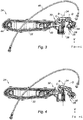
figure 2 est une vue de face qui illustre le levier de préhension de la poignée de lafigure 1 dans sa position de repos et un premier système de sécurité inertiel, avec le châssis de la poignée ; - la
figure 3 est une vue de dos qui illustre le levier de transmission dans sa position de repos, sans le châssis ; - la
figure 4 est une vue de dos qui illustre le levier de transmission dans sa position d'actionnement, sans le châssis ; - la
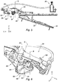
figure 5 est une vue de dessus, qui illustre le levier de transmission dans sa position de commande, sans le châssis ; - la
figure 6 est une vue de détail en perspective qui illustre le levier de préhension dans sa position de commande et le levier de transmission dans sa position d'actionnement ; - la
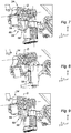
figure 7 est une vue de détail en perspective qui illustre le balancier dans sa position de repos et le levier de transmission dans sa position de repos ; - la
figure 8 est une vue de détail en perspective qui illustre le balancier dans sa position de repos et le levier de transmission dans sa position d'actionnement ; - la
figure 9 est une vue de détail en perspective qui illustre le balancier dans sa position de blocage et le levier de transmission dans sa position de repos ; - la
figure 10 est une vue de détail en perspective qui illustre le balancier dans sa position de blocage et le levier de transmission dans une position bloquée ; - la
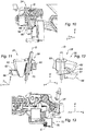
figure 11 est une vue de détail en perspective et en coupe longitudinale qui illustre le balancier ; - la
figure 12 est une vue de détail en perspective qui illustre le balancier ; - la
figure 13 est une vue de détail en perspective qui illustre un second système de sécurité inertiel selon l'invention. - Dans la présente demande, les termes « haut », « bas », « supérieur », « inférieur », « horizontal », « vertical », et leurs dérivés font référence à la position ou à l'orientation d'un élément ou d'un composant, cette position ou cette orientation étant considérée lorsque le véhicule est en configuration de service sur un sol horizontal.
- De plus, pour clarifier la description et les revendications, on adoptera à titre non limitatif la terminologie longitudinal, vertical et transversal en référence au trièdre L, V, T indiqué aux figures.
- Sur l'ensemble de ces figures, des références identiques ou analogues représentent des organes ou ensembles d'organes identiques ou analogues.
- A noter que dans la présente demande de brevet, les termes « avant » et « arrière » doivent s'entendre par rapport à la direction générale longitudinale du véhicule, c'est-à-dire de la gauche vers la droite de la
figure 1 . - On a représenté à la
figure 1 un véhicule automobile 10 qui est équipé d'un système de verrouillage 12 pour ouvrant, selon l'invention. - Le système de verrouillage 12 comprend un ouvrant 14 qui s'étend longitudinalement, dans un plan vertical, depuis un bord avant 16 jusqu'à un bord arrière 18, l'ouvrant 14 comprenant une zone centrale 20 qui est interposée longitudinalement entre le bord avant 16 et le bord arrière 18.
- L'ouvrant 14 est délimité par une face externe 22 d'habillage qui est agencée à l'extérieur du véhicule.
- Aussi, l'ouvrant 14 est monté pivotant entre une position fermée, illustrée à la
figure 1 , et une position ouverte, autour d'un axe A d'ouverture qui s'étend verticalement, au voisinage du bord avant 16 de l'ouvrant 14. - En référence aux
figures 2 à 4 , le système de verrouillage 12 comporte une poignée 24 qui comprend un châssis 26, un mécanisme d'ouverture d'un verrou 36 de l'ouvrant 14, et un premier système de sécurité inertiel 28 qui vise à empêcher l'ouverture intempestive de l'ouvrant 14 en cas de choc violent du véhicule 10 contre un obstacle. - Le châssis 26 présente globalement la forme d'une plaque qui s'étend dans le plan de l'ouvrant 14 et qui est fixée sur une structure (non représentée) de l'ouvrant par des vis (non représentées) par exemple.
- Le mécanisme d'ouverture du verrou 36 comporte un levier de préhension 30, un élément de préhension 32 et un levier de transmission 34.
- Le levier de préhension 30 est monté mobile en rotation par rapport au châssis 26 autour d'un premier axe B de rotation vertical, entre une position de repos illustrée aux
figures 2 et3 , et une position de commande pour l'ouverture du verrou 36 de l'ouvrant 14, illustrée auxfigures 4 et5 . - Le levier de préhension 30 est rappelé élastiquement vers sa position de repos par un ressort 38 hélicoïdal qui s'étend verticalement autour de l'axe B de rotation du levier de préhension et qui est relié au châssis 26.
- De façon complémentaire, l'élément de préhension 32 est conçu pour permettre à un utilisateur d'actionner le levier de préhension 30.
- A cet effet, comme on peut le voir à la
figure 1 , l'élément de préhension 32 est agencé d'un côté externe de l'ouvrant 14, dans un logement 40 formé par la face externe 22 de l'ouvrant 14, l'élément de préhension 32 étant solidaire du levier de préhension 30 pour entraîner le levier de préhension 30 en rotation lorsque l'utilisateur actionne l'élément de préhension 32. - L'élément de préhension 32 présente une forme de poignée allongée qui s'étend longitudinalement depuis une extrémité avant 42 jusqu'à son extrémité arrière 44.
- On notera que l'élément de préhension 32 est représenté sans son capot d'habillage sur les
figures 2 , et4 à 6 , capot d'habillage qui affleure la face externe 22 de l'ouvrant lorsque le levier de préhension 30 occupe sa position de repos. - Aussi, le levier de préhension 30 est agencé de façon à entraîner en mouvement le levier de transmission 34, afin d'actionner l'ouverture du verrou de l'ouvrant 14.
- Dans ce but, le levier de transmission 34 est monté pivotant par rapport au châssis 26 autour d'un second axe C de rotation transversal, entre une position de repos illustrée aux
figures 2 et3 , et une position d'actionnement illustrée auxfigures 4 et5 , dans laquelle le levier de transmission 34 actionne l'ouverture du verrou de l'ouvrant 14. - De plus, en référence à la
figure 6 , l'extrémité avant 48 du levier de préhension 30 délimite une came 50 qui présente un profil 51 globalement de la forme d'une portion sphérique. - Complémentairement, l'extrémité arrière 52 du levier de transmission 34 comporte un suiveur 54 délimitant une face d'appui 56 qui s'étend transversalement en regard de la came 50.
- La came 50 et le suiveur 54 sont agencés de façon à transformer le mouvement de rotation du levier de préhension 30 autour de son axe B vertical, en un mouvement de rotation du levier d'actionnement 34 autour de son axe C transversal.
- Selon un exemple de réalisation préféré de l'invention, la poignée 24 est une poignée du type affleurante, aussi appelée poignée « flush » selon la dénomination anglaise, c'est-à-dire que l'élément de préhension 32 affleure la face externe 22 de l'ouvrant 14 et se fond visuellement avec la face externe 22 de l'ouvrant 14 lorsque le levier de préhension 30 occupe sa position de repos.
- Ce type de poignée 24 est décrit dans le document
EP-A1-3106596 auquel il convient de se rapporter pour plus de détails. - Selon un autre aspect, le système de sécurité inertiel 28 comporte un balancier 58 représenté en détails aux
figures 11 et 12 , qui s'étend longitudinalement, depuis une extrémité arrière 60, jusqu'à une extrémité avant 62 qui porte une masse d'inertie 64. - L'extrémité avant 62 du balancier 58 comprend un doigt de blocage 66 qui fait saillie longitudinalement vers l'avant et qui délimite une face de blocage 67 s'étendant radialement et préférentiellement perpendiculairement à l'axe D de rotation du balancier 58.
- La face de blocage 67 du balancier 58 est conçue pour coopérer avec une face de blocage 68 délimitée par le levier de transmission 34, qui s'étend globalement parallèlement à la face de blocage 67 du balancier 58, pour s'opposer à la rotation du levier de transmission 34 depuis sa position de repos vers sa position d'actionnement, en cas de choc du véhicule, comme on peut le voir à la
figure 10 . - A cet effet, le balancier 58 est monté pivotant autour d'un troisième axe D de rotation vertical, entre une position de repos illustrée aux
figures 7 et 8 , et une position de blocage illustrée auxfigures 9 et10 , dans laquelle le doigt de blocage 66 du balancier 58 est positionné sur le chemin du levier de transmission 34, de sorte que la face de blocage 68 du levier de transmission 34 heurte le doigt de blocage du balancier 58 pour empêcher la rotation du levier de transmission 3, de façon à bloquer l'ouverture de l'ouvrant 14. - L'axe D de rotation du balancier 58 est interposé entre l'extrémité arrière 60 et l'extrémité avant 62 du balancier 58.
- Selon un exemple de réalisation préféré de l'invention, le système de sécurité inertiel 28 est un système réversible, c'est-à-dire que le balancier 58 occupe sa position de blocage de façon temporaire, pour permettre l'ouverture de l'ouvrant 14 dans un court délai suivant l'actionnement du système de sécurité inertiel 28.
- Dans ce but, en référence à la
figure 11 , le balancier 58 est équipé d'un ressort hélicoïdal 70 qui s'étend autour de l'axe D de rotation du balancier 58 et qui coopère avec le châssis pour rappeler élastiquement le balancier 58 depuis sa position de blocage vers sa position de repos. - Ainsi, le balancier 58 est rappelé élastiquement dans sa position initiale de repos lorsque l'accélération appliquée sur le balancier 58 redevient nulle.
- Le balancier 58 est conçu pour être entraîné depuis sa position de repos jusqu'à sa position de blocage lorsque l'accélération de la première masse d'inertie 64 est comprise dans une première plage de valeurs comprise entre 5G et 15G par exemple, l'unité G d'accélération valant 9,80665 m·s-2.
- Le premier système de sécurité inertiel 28 est donc très réactif et rapide à passer dans une position de blocage.
- Selon l'invention, la masse d'inertie 64 du balancier 58 est agencée longitudinalement en avant de l'extrémité avant 42 de l'élément de préhension 30, comme on peut le voir aux
figures 2 ,3 et5 . - Plus particulièrement, la masse d'inertie 64 du balancier 58 est agencée longitudinalement en avant de l'axe B de rotation du levier de préhension 30, l'axe B de rotation du levier de préhension 30 étant agencé en avant de l'extrémité avant 42 de l'élément de préhension 30.
- D'une façon générale, en référence à la
figure 1 , la masse d'inertie 64 est agencée longitudinalement entre la zone centrale 20 de l'ouvrant 14 et l'axe de rotation B du levier de préhension 30. - En effet, on constate qu'au court d'un choc violent du véhicule contre un obstacle, la zone centrale 20 de l'ouvrant 14 se déforme avec plus de vélocité que la périphérie de l'ouvrant 14, de part la plus grande souplesse de la zone centrale 20 de l'ouvrant 14 par rapport à la périphérie de l'ouvrant 14.
- Ainsi, plus la masse d'inertie 64 du système de sécurité inertiel 28 est agencée proche de la zone centrale 20 de l'ouvrant 14, plus le système de sécurité inertiel 28 est réactif pour bloquer l'ouverture le mécanisme d'ouverture de l'ouvrant 14.
- Selon une variante de réalisation de l'invention représentée à la
figure 13 , la poignée 24 comporte un second système de sécurité inertiel 72 qui comprend un balancier 74 qui porte une masse d'inertie 76. - Le balancier 74 est monté pivotant autour d'un axe E de rotation vertical, entre une position de repos illustrée à la
figure 13 , dans laquelle le balancier autorise la rotation du levier de transmission 34 jusqu'à sa position d'actionnement, et une position de blocage (non représentée) dans laquelle le balancier 74 empêche la rotation du levier de transmission 34, en cas de choc. - La masse d'inertie 76 du second système de sécurité inertiel 72 est agencée longitudinalement en avant de l'extrémité avant 42 de l'élément de préhension 32, pour les mêmes raisons décrites précédemment pour le premier système de sécurité inertiel 28.
- De plus, le second système de sécurité inertiel 72 et le premier système de sécurité inertiel 28 sont conçus pour être activés chacun en réponse à une plage d'intensités de chocs différente.
- De préférence, le second système de sécurité inertiel 72 est un système du type irréversible, c'est-à-dire que le balancier 74 reste dans sa position de blocage après avoir subi une accélération.
- Ce type de système inertiel irréversible est décrit notamment dans le document
WO-2006003197 auquel il convient de se rapporter pour plus de détails. - La présente description de l'invention est donnée à titre d'exemple non limitatif.
- L'axe D de rotation du balancier 58 du premier système de sécurité inertiel, l'axe B de rotation du levier de préhension 30 et l'axe E de rotation du balancier 74 du second système de sécurité inertiel sont tous les trois parallèles.
Claims (8)
- Système de verrouillage (12) pour ouvrant de véhicule (10) automobile comprenant un ouvrant (14) qui s'étend longitudinalement, dans un plan vertical, depuis un bord avant (16) jusqu'à un bord arrière (18), l'ouvrant (14) comprenant une zone centrale (20) qui est interposée longitudinalement entre le bord (16) avant et le bord arrière (18), et le système de verrouillage (12) comportant une poignée (24) qui comprend :- un châssis (26) qui est adapté pour être fixé sur l'ouvrant (14),- un levier de préhension (30) qui est monté mobile en rotation par rapport au châssis (26) autour d'un premier axe (B) de rotation, entre au moins une position de repos et une position de commande pour l'ouverture d'un verrou de l'ouvrant (14),- un élément de préhension (32) qui est agencé d'un côté externe de l'ouvrant (14) et qui est conçu pour permettre à un utilisateur d'actionner le levier de préhension (30), l'élément de préhension (32) étant délimité longitudinalement par une extrémité avant (42) et une extrémité arrière (44),- un levier de transmission (34) qui est monté pivotant par rapport au châssis (26) autour d'un second axe (C) de rotation, entre une position de repos et une position d'actionnement dans laquelle le levier de transmission (34) actionne l'ouverture d'un verrou, le levier de transmission (34) étant entraîné en rotation par le levier de préhension (30),- au moins un premier système de sécurité inertiel (28) qui est monté sur le châssis (26) et qui comporte un balancier (58) qui porte une masse d'inertie (64), le balancier (58) étant monté pivotant entre une position de repos et une position de blocage dans laquelle le balancier (58) empêche la rotation du levier de transmission (34), en cas de choc,caractérisé en ce que l'axe (B) de rotation du levier de préhension (30) s'étend globalement verticalement à l'avant de l'extrémité avant (42) de l'élément de préhension (32), la masse d'inertie (64) étant agencée longitudinalement en avant de l'axe (B) de rotation du levier de préhension (30).
- Système de verrouillage (12) selon la revendication précédente, caractérisé en ce que la masse d'inertie (64) est adaptée pour être agencée longitudinalement entre la zone centrale (20) de l'ouvrant (14) et l'axe (B) de rotation du levier de préhension (30).
- Système de verrouillage (12) selon l'une quelconque des revendications précédentes, caractérisé en ce que l'élément de préhension (32) présente une forme allongée qui s'étend longitudinalement depuis son extrémité avant (42) jusqu'à son extrémité arrière (44).
- Système de verrouillage (12) selon l'une quelconque des revendications précédentes, caractérisé en ce que le second axe (C) de rotation du levier de transmission (34) s'étend transversalement, perpendiculairement à l'axe (B) de rotation du levier de préhension (30).
- Système de verrouillage (12) selon l'une quelconque des revendications précédentes, caractérisé en ce que le balancier (58) s'étend longitudinalement, depuis une extrémité arrière (60), jusqu'à une extrémité avant (62) qui porte la masse d'inertie (64) et qui comprend un doigt de blocage (66) conçu pour coopérer avec une face de blocage (68) délimitée par le levier de transmission (34) pour s'opposer à la rotation du levier de transmission (34) en cas de choc, le balancier (58) étant monté pivotant autour d'un troisième axe (D) de rotation vertical qui est interposé entre l'extrémité arrière (60) et l'extrémité avant (62) du balancier (58).
- Système de verrouillage (12) selon l'une quelconque des revendications précédentes, caractérisé en ce que l'élément de préhension (32) est adapté pour affleurer une face externe (22) de l'ouvrant (14) lorsque le levier de préhension (30) occupe sa position de repos, ladite face externe (22) étant destinée à être agencée à l'extérieur du véhicule.
- Système de verrouillage (12) selon l'une quelconque des revendications précédentes, caractérisé en ce que la poignée (24) comporte un second système de sécurité inertiel (72) comportant un balancier (74) qui porte une masse d'inertie (76), ledit balancier (74) étant monté pivotant entre une position de repos et une position de blocage dans laquelle le balancier empêche la rotation du levier de transmission (34), en cas de choc, la masse d'inertie (76) du second système de sécurité (72) étant agencée longitudinalement en avant de l'extrémité avant (42) de l'élément de préhension (32), et en ce que le second système (72) de sécurité et le premier système de sécurité (28) sont conçus pour être activés chacun en réponse à une plage d'intensités de chocs différente.
- Ouvrant (14) de véhicule (10) automobile comprenant un système de verrouillage selon l'une quelconque des revendications précédentes.
Priority Applications (5)
| Application Number | Priority Date | Filing Date | Title |
|---|---|---|---|
| EP17187576.8A EP3447218B1 (fr) | 2017-08-23 | 2017-08-23 | Système de verrouillage équipé d'une poignée et d'un système inertiel déporté |
| PCT/EP2018/072307 WO2019038194A1 (fr) | 2017-08-23 | 2018-08-17 | Système de verrouillage équipé d'une poignée et d'un système inertiel déporté |
| JP2020511218A JP7206561B2 (ja) | 2017-08-23 | 2018-08-17 | ハンドルおよび離れた位置にある慣性システムを備える施錠システム |
| CN201880061717.3A CN111133166B (zh) | 2017-08-23 | 2018-08-17 | 装配有把手和远程定位的惯性系统的锁定系统 |
| US16/798,960 US10975598B2 (en) | 2017-08-23 | 2020-02-24 | Locking system equipped with a handle and with a remotely situated inertial system |
Applications Claiming Priority (1)
| Application Number | Priority Date | Filing Date | Title |
|---|---|---|---|
| EP17187576.8A EP3447218B1 (fr) | 2017-08-23 | 2017-08-23 | Système de verrouillage équipé d'une poignée et d'un système inertiel déporté |
Publications (2)
| Publication Number | Publication Date |
|---|---|
| EP3447218A1 EP3447218A1 (fr) | 2019-02-27 |
| EP3447218B1 true EP3447218B1 (fr) | 2020-06-03 |
Family
ID=59686892
Family Applications (1)
| Application Number | Title | Priority Date | Filing Date |
|---|---|---|---|
| EP17187576.8A Active EP3447218B1 (fr) | 2017-08-23 | 2017-08-23 | Système de verrouillage équipé d'une poignée et d'un système inertiel déporté |
Country Status (5)
| Country | Link |
|---|---|
| US (1) | US10975598B2 (fr) |
| EP (1) | EP3447218B1 (fr) |
| JP (1) | JP7206561B2 (fr) |
| CN (1) | CN111133166B (fr) |
| WO (1) | WO2019038194A1 (fr) |
Families Citing this family (9)
| Publication number | Priority date | Publication date | Assignee | Title |
|---|---|---|---|---|
| ES2765822T3 (es) * | 2017-08-23 | 2020-06-11 | U Shin Italia Spa | Sistema de enclavamiento para batiente de vehículo automóvil que incluye una manija del tipo a ras |
| FR3094737B1 (fr) * | 2019-04-08 | 2021-04-09 | Akwel Vigo Spain | Système de poignée avec dispositif de sécurité. |
| CN110219528B (zh) * | 2019-07-02 | 2024-01-16 | 宁波华德汽车零部件有限公司 | 一种车用把手结构 |
| JP7313996B2 (ja) * | 2019-09-11 | 2023-07-25 | 株式会社アルファ | 車両のハンドル装置 |
| KR102923036B1 (ko) * | 2019-12-16 | 2026-02-04 | 현대자동차 주식회사 | 차량용 아웃사이드 도어 핸들 조립체 |
| JP7533257B2 (ja) * | 2021-02-03 | 2024-08-14 | マツダ株式会社 | 車両のドアハンドル構造 |
| EP4202162B1 (fr) * | 2021-12-24 | 2026-05-20 | Minebea Accesssolutions Italia S P A | Poignée de porte arrière |
| EP4273358B1 (fr) * | 2022-05-03 | 2025-11-19 | Minebea AccessSolutions Italia S.p.A. | Agencement de poignée avec système de volet |
| US20260085551A1 (en) * | 2024-09-23 | 2026-03-26 | Ford Global Technologies, Llc | Vehicle door latch assembly with cable blocker |
Family Cites Families (36)
| Publication number | Priority date | Publication date | Assignee | Title |
|---|---|---|---|---|
| US2317699A (en) * | 1941-08-21 | 1943-04-27 | Arthur S Thompson | Automobile door lock |
| US2317700A (en) * | 1942-06-11 | 1943-04-27 | Arthur S Thompson | Door lock |
| JPS6010041B2 (ja) * | 1975-12-19 | 1985-03-14 | 旭化成株式会社 | ゴム状重合体の取得法 |
| JPS6010041Y2 (ja) * | 1978-10-20 | 1985-04-06 | ナイルス部品株式会社 | 車両用コンビネ−ションスイッチ |
| FR2789433B1 (fr) * | 1999-02-05 | 2001-04-13 | Valeo Securite Habitacle | Systeme de securite pour un ouvrant de vehicule automobile |
| US6363577B1 (en) * | 2000-08-25 | 2002-04-02 | Adac Plastics, Inc. | Motor vehicle door handle assembly with maximized bearing interface |
| DE10057019A1 (de) * | 2000-11-17 | 2002-05-23 | Daimler Chrysler Ag | Türgriffanordnung für eine Fahrzeugtür |
| CA2444516C (fr) * | 2002-10-10 | 2011-12-20 | Intier Automotive Closures Inc. | Poignee exterieure de deverrouillage |
| ITMI20022250A1 (it) | 2002-10-23 | 2004-04-24 | Valeo Sicurezza Abitacolo Spa | Maniglia per portiere, sportelli o simili, in particolare |
| FR2869937B1 (fr) * | 2004-05-05 | 2007-12-21 | Peugeot Citroen Automobiles Sa | Dispositif d'ouverture d'un ouvrant de vehicule automobile a securite renforcee en cas de choc, et procede de montage du dispositif sur l'ouvrant |
| ITRM20040337A1 (it) | 2004-07-07 | 2004-10-07 | Valeo Sicurezza Abitacolo Spa | Maniglia di portiera, in particolare di autoveicolo, con sistema di sicurezza inerziale. |
| US7407203B2 (en) * | 2004-08-18 | 2008-08-05 | Donnelly Corporation | Vehicle door handle |
| US7070216B2 (en) * | 2004-09-09 | 2006-07-04 | Siegel-Robert, Inc. | Vehicle door handle assembly |
| US7568744B2 (en) * | 2005-09-22 | 2009-08-04 | Nissan Technical Center North America, Inc. | Vehicle door handle assembly |
| KR100737001B1 (ko) * | 2005-10-07 | 2007-07-09 | 현대자동차주식회사 | 차량 도어핸들어셈블리의 안전기구 |
| US7635151B2 (en) * | 2006-06-08 | 2009-12-22 | Illinois Tool Works Inc. | Release handle with integrated inertia locking mechanism |
| ITRM20060660A1 (it) | 2006-12-06 | 2008-06-07 | Valeo Sicurezza Abitacolo Spa | Maniglia per veicoli con dispositivo di sicurezza |
| IT1390596B1 (it) * | 2008-07-07 | 2011-09-09 | Valeo Spa | Maniglia con dispositivo di sicurezza per veicoli |
| IT1391437B1 (it) * | 2008-10-02 | 2011-12-23 | Valeo Spa | Maniglia per veicoli con meccanismo di sblocco migliorato |
| US8894108B2 (en) * | 2009-02-13 | 2014-11-25 | Adac Plastics, Inc. | Release handle assembly having inertial blocking member with blocking member retainer |
| IT1398513B1 (it) * | 2009-06-12 | 2013-03-01 | Valeo Spa | Maniglia di un battente di un autoveicolo |
| US8366159B2 (en) * | 2010-01-06 | 2013-02-05 | Ford Global Technologies, Llc | Multi-lever bi-directional inertia catch mechanism |
| GB2477085B (en) * | 2010-01-15 | 2014-08-20 | Jaguar Land Rover Ltd | Retractable handle for a door or the like |
| DE102010016869A1 (de) * | 2010-05-10 | 2011-11-10 | Huf Hülsbeck & Fürst Gmbh & Co. Kg | Griffvorrichtung insbesondere für ein Fahrzeug |
| DE102011115009A1 (de) * | 2010-10-12 | 2012-04-12 | Magna Mirrors Holding Gmbh | Betätigungsvorrichtung für ein Türschloss |
| EP2735676B1 (fr) | 2012-11-20 | 2017-02-15 | U-Shin Italia S.p.A. | Ensemble de poignée de panneau de véhicule |
| US9062477B2 (en) * | 2012-11-28 | 2015-06-23 | Huf North America Automotive Parts Mfg. Corp. | Vehicular door handle assembly with inertial secondary catch position |
| US9567777B1 (en) * | 2012-12-03 | 2017-02-14 | Adac Plastics, Inc. | Inertial blocking member subassembly with negative-acceleration inertial blocking member accelerator |
| JP5934159B2 (ja) * | 2013-09-02 | 2016-06-15 | 本田技研工業株式会社 | ドアアウタハンドル |
| DE102014114378A1 (de) * | 2014-10-02 | 2016-04-07 | Huf Hülsbeck & Fürst Gmbh & Co. Kg | Arretierelement und Handhabe |
| JP6504867B2 (ja) * | 2015-03-16 | 2019-04-24 | 株式会社アルファ | 車両のドアハンドル装置 |
| EP3274532B1 (fr) * | 2015-03-25 | 2021-06-30 | Jaguar Land Rover Limited | Agencement de poignée rétractable |
| JP6420703B2 (ja) | 2015-03-30 | 2018-11-07 | アイシン精機株式会社 | 車両用ドアハンドル装置 |
| EP3078793B1 (fr) * | 2015-04-10 | 2019-12-25 | Huf Hülsbeck & Fürst GmbH & Co. KG | Poignée extérieure de porte pour un véhicule automobile |
| EP3106594A1 (fr) | 2015-06-16 | 2016-12-21 | U-Shin Italia S.p.A. | Poignée pour une portière de véhicule |
| ES2765822T3 (es) * | 2017-08-23 | 2020-06-11 | U Shin Italia Spa | Sistema de enclavamiento para batiente de vehículo automóvil que incluye una manija del tipo a ras |
-
2017
- 2017-08-23 EP EP17187576.8A patent/EP3447218B1/fr active Active
-
2018
- 2018-08-17 WO PCT/EP2018/072307 patent/WO2019038194A1/fr not_active Ceased
- 2018-08-17 CN CN201880061717.3A patent/CN111133166B/zh active Active
- 2018-08-17 JP JP2020511218A patent/JP7206561B2/ja active Active
-
2020
- 2020-02-24 US US16/798,960 patent/US10975598B2/en active Active
Non-Patent Citations (1)
| Title |
|---|
| None * |
Also Published As
| Publication number | Publication date |
|---|---|
| JP7206561B2 (ja) | 2023-01-18 |
| WO2019038194A1 (fr) | 2019-02-28 |
| US20200190865A1 (en) | 2020-06-18 |
| US10975598B2 (en) | 2021-04-13 |
| JP2020531717A (ja) | 2020-11-05 |
| CN111133166A (zh) | 2020-05-08 |
| CN111133166B (zh) | 2021-11-02 |
| EP3447218A1 (fr) | 2019-02-27 |
Similar Documents
| Publication | Publication Date | Title |
|---|---|---|
| EP3447218A1 (fr) | Système de verrouillage équipé d'une poignée et d'un système inertiel déporté | |
| EP3447220B1 (fr) | Système de verrouillage pour ouvrant de véhicule automobile comportant une poignée du type affleurante | |
| EP2432954B1 (fr) | Poignee d'un ouvrant de vehicule automobile | |
| EP1766164B1 (fr) | Poignee de porte, en particulier de vehicule automobile, avec systeme de securite inertiel | |
| EP3998389B1 (fr) | Dispositif de commande d'ouverture à blocage de sécurité inertiel réversible et irréversible | |
| EP2616616B1 (fr) | Poignee d'ouvrant de vehicule comprenant une masse inertielle et un fusible | |
| FR2802564A1 (fr) | Systeme de securite d'un ouvrant de vehicule automobile equipe de commutateurs sans actionnement mecanique | |
| FR2848235A1 (fr) | Serrure pour capot de vehicule automobile | |
| EP2440728B1 (fr) | Poignée d'un ouvrant de véhicule automobile | |
| EP3722544A1 (fr) | Système de poignée avec dispositif de sécurité | |
| WO2012042065A1 (fr) | Poignée d'ouvrant de véhicule comprenant deux leviers | |
| WO2020020656A1 (fr) | Poignée d'ouvrant de véhicule automobile munie d'un système de sécurité inertiel | |
| FR2885574A1 (fr) | Pedalier de vehicule automobile apte, en cas de choc frontal sur le vehicule, a se retracter | |
| EP1867814B1 (fr) | Dispositif de verrouillage réglable d'un capot de véhicule | |
| EP3596292B1 (fr) | Commande d'ouverture exterieure avec systeme inertiel de blocage protege | |
| EP0587465A1 (fr) | Commande extérieure de porte notamment pour véhicule automobile | |
| EP3044020B1 (fr) | Hayon pour véhicule automobile avec ossature de support et véhicule correspondant | |
| FR3077836A1 (fr) | Systeme de prevention contre l’ouverture non intentionnelle d’un dispositif de rangement en cas de choc. | |
| FR3153630A1 (fr) | Système anti-g pour poignée de porte de véhicule automobile et poignée de porte comprenant un tel système | |
| FR3125840A1 (fr) | Dispositif de rangement à couvercle pivotant pour véhicule doté d’un mécanisme de sécurité contre l’ouverture non intentionnelle en cas de choc | |
| EP4650198A1 (fr) | Raidisseur pour le blocage d'un ouvrant d'un véhicule | |
| FR92274E (fr) | ||
| WO2024013438A1 (fr) | Boîte de rangement pour véhicule automobile comprenant un dispositif de fermeture d'un tiroir | |
| FR2890023A1 (fr) | Systeme d'ejection d'un capot de vehicule automobile en cas de collision contre le capot | |
| FR3096710A1 (fr) | Dispositif de commande du mécanisme d'ouverture d'un ouvrant de véhicule automobile |
Legal Events
| Date | Code | Title | Description |
|---|---|---|---|
| PUAI | Public reference made under article 153(3) epc to a published international application that has entered the european phase |
Free format text: ORIGINAL CODE: 0009012 |
|
| STAA | Information on the status of an ep patent application or granted ep patent |
Free format text: STATUS: THE APPLICATION HAS BEEN PUBLISHED |
|
| AK | Designated contracting states |
Kind code of ref document: A1 Designated state(s): AL AT BE BG CH CY CZ DE DK EE ES FI FR GB GR HR HU IE IS IT LI LT LU LV MC MK MT NL NO PL PT RO RS SE SI SK SM TR |
|
| AX | Request for extension of the european patent |
Extension state: BA ME |
|
| STAA | Information on the status of an ep patent application or granted ep patent |
Free format text: STATUS: REQUEST FOR EXAMINATION WAS MADE |
|
| 17P | Request for examination filed |
Effective date: 20190731 |
|
| RBV | Designated contracting states (corrected) |
Designated state(s): AL AT BE BG CH CY CZ DE DK EE ES FI FR GB GR HR HU IE IS IT LI LT LU LV MC MK MT NL NO PL PT RO RS SE SI SK SM TR |
|
| GRAP | Despatch of communication of intention to grant a patent |
Free format text: ORIGINAL CODE: EPIDOSNIGR1 |
|
| STAA | Information on the status of an ep patent application or granted ep patent |
Free format text: STATUS: GRANT OF PATENT IS INTENDED |
|
| INTG | Intention to grant announced |
Effective date: 20200203 |
|
| GRAS | Grant fee paid |
Free format text: ORIGINAL CODE: EPIDOSNIGR3 |
|
| GRAA | (expected) grant |
Free format text: ORIGINAL CODE: 0009210 |
|
| STAA | Information on the status of an ep patent application or granted ep patent |
Free format text: STATUS: THE PATENT HAS BEEN GRANTED |
|
| AK | Designated contracting states |
Kind code of ref document: B1 Designated state(s): AL AT BE BG CH CY CZ DE DK EE ES FI FR GB GR HR HU IE IS IT LI LT LU LV MC MK MT NL NO PL PT RO RS SE SI SK SM TR |
|
| REG | Reference to a national code |
Ref country code: GB Ref legal event code: FG4D Free format text: NOT ENGLISH |
|
| REG | Reference to a national code |
Ref country code: CH Ref legal event code: EP Ref country code: AT Ref legal event code: REF Ref document number: 1277177 Country of ref document: AT Kind code of ref document: T Effective date: 20200615 |
|
| REG | Reference to a national code |
Ref country code: DE Ref legal event code: R096 Ref document number: 602017017570 Country of ref document: DE |
|
| REG | Reference to a national code |
Ref country code: LT Ref legal event code: MG4D |
|
| PG25 | Lapsed in a contracting state [announced via postgrant information from national office to epo] |
Ref country code: SE Free format text: LAPSE BECAUSE OF FAILURE TO SUBMIT A TRANSLATION OF THE DESCRIPTION OR TO PAY THE FEE WITHIN THE PRESCRIBED TIME-LIMIT Effective date: 20200603 Ref country code: LT Free format text: LAPSE BECAUSE OF FAILURE TO SUBMIT A TRANSLATION OF THE DESCRIPTION OR TO PAY THE FEE WITHIN THE PRESCRIBED TIME-LIMIT Effective date: 20200603 Ref country code: NO Free format text: LAPSE BECAUSE OF FAILURE TO SUBMIT A TRANSLATION OF THE DESCRIPTION OR TO PAY THE FEE WITHIN THE PRESCRIBED TIME-LIMIT Effective date: 20200903 Ref country code: GR Free format text: LAPSE BECAUSE OF FAILURE TO SUBMIT A TRANSLATION OF THE DESCRIPTION OR TO PAY THE FEE WITHIN THE PRESCRIBED TIME-LIMIT Effective date: 20200904 Ref country code: FI Free format text: LAPSE BECAUSE OF FAILURE TO SUBMIT A TRANSLATION OF THE DESCRIPTION OR TO PAY THE FEE WITHIN THE PRESCRIBED TIME-LIMIT Effective date: 20200603 |
|
| REG | Reference to a national code |
Ref country code: NL Ref legal event code: MP Effective date: 20200603 |
|
| PG25 | Lapsed in a contracting state [announced via postgrant information from national office to epo] |
Ref country code: HR Free format text: LAPSE BECAUSE OF FAILURE TO SUBMIT A TRANSLATION OF THE DESCRIPTION OR TO PAY THE FEE WITHIN THE PRESCRIBED TIME-LIMIT Effective date: 20200603 Ref country code: LV Free format text: LAPSE BECAUSE OF FAILURE TO SUBMIT A TRANSLATION OF THE DESCRIPTION OR TO PAY THE FEE WITHIN THE PRESCRIBED TIME-LIMIT Effective date: 20200603 Ref country code: BG Free format text: LAPSE BECAUSE OF FAILURE TO SUBMIT A TRANSLATION OF THE DESCRIPTION OR TO PAY THE FEE WITHIN THE PRESCRIBED TIME-LIMIT Effective date: 20200903 Ref country code: RS Free format text: LAPSE BECAUSE OF FAILURE TO SUBMIT A TRANSLATION OF THE DESCRIPTION OR TO PAY THE FEE WITHIN THE PRESCRIBED TIME-LIMIT Effective date: 20200603 |
|
| REG | Reference to a national code |
Ref country code: AT Ref legal event code: MK05 Ref document number: 1277177 Country of ref document: AT Kind code of ref document: T Effective date: 20200603 |
|
| PG25 | Lapsed in a contracting state [announced via postgrant information from national office to epo] |
Ref country code: NL Free format text: LAPSE BECAUSE OF FAILURE TO SUBMIT A TRANSLATION OF THE DESCRIPTION OR TO PAY THE FEE WITHIN THE PRESCRIBED TIME-LIMIT Effective date: 20200603 Ref country code: AL Free format text: LAPSE BECAUSE OF FAILURE TO SUBMIT A TRANSLATION OF THE DESCRIPTION OR TO PAY THE FEE WITHIN THE PRESCRIBED TIME-LIMIT Effective date: 20200603 |
|
| PG25 | Lapsed in a contracting state [announced via postgrant information from national office to epo] |
Ref country code: RO Free format text: LAPSE BECAUSE OF FAILURE TO SUBMIT A TRANSLATION OF THE DESCRIPTION OR TO PAY THE FEE WITHIN THE PRESCRIBED TIME-LIMIT Effective date: 20200603 Ref country code: PT Free format text: LAPSE BECAUSE OF FAILURE TO SUBMIT A TRANSLATION OF THE DESCRIPTION OR TO PAY THE FEE WITHIN THE PRESCRIBED TIME-LIMIT Effective date: 20201006 Ref country code: AT Free format text: LAPSE BECAUSE OF FAILURE TO SUBMIT A TRANSLATION OF THE DESCRIPTION OR TO PAY THE FEE WITHIN THE PRESCRIBED TIME-LIMIT Effective date: 20200603 Ref country code: ES Free format text: LAPSE BECAUSE OF FAILURE TO SUBMIT A TRANSLATION OF THE DESCRIPTION OR TO PAY THE FEE WITHIN THE PRESCRIBED TIME-LIMIT Effective date: 20200603 Ref country code: SM Free format text: LAPSE BECAUSE OF FAILURE TO SUBMIT A TRANSLATION OF THE DESCRIPTION OR TO PAY THE FEE WITHIN THE PRESCRIBED TIME-LIMIT Effective date: 20200603 Ref country code: EE Free format text: LAPSE BECAUSE OF FAILURE TO SUBMIT A TRANSLATION OF THE DESCRIPTION OR TO PAY THE FEE WITHIN THE PRESCRIBED TIME-LIMIT Effective date: 20200603 Ref country code: CZ Free format text: LAPSE BECAUSE OF FAILURE TO SUBMIT A TRANSLATION OF THE DESCRIPTION OR TO PAY THE FEE WITHIN THE PRESCRIBED TIME-LIMIT Effective date: 20200603 |
|
| PG25 | Lapsed in a contracting state [announced via postgrant information from national office to epo] |
Ref country code: SK Free format text: LAPSE BECAUSE OF FAILURE TO SUBMIT A TRANSLATION OF THE DESCRIPTION OR TO PAY THE FEE WITHIN THE PRESCRIBED TIME-LIMIT Effective date: 20200603 Ref country code: PL Free format text: LAPSE BECAUSE OF FAILURE TO SUBMIT A TRANSLATION OF THE DESCRIPTION OR TO PAY THE FEE WITHIN THE PRESCRIBED TIME-LIMIT Effective date: 20200603 Ref country code: IS Free format text: LAPSE BECAUSE OF FAILURE TO SUBMIT A TRANSLATION OF THE DESCRIPTION OR TO PAY THE FEE WITHIN THE PRESCRIBED TIME-LIMIT Effective date: 20201003 |
|
| REG | Reference to a national code |
Ref country code: DE Ref legal event code: R097 Ref document number: 602017017570 Country of ref document: DE |
|
| PG25 | Lapsed in a contracting state [announced via postgrant information from national office to epo] |
Ref country code: MC Free format text: LAPSE BECAUSE OF FAILURE TO SUBMIT A TRANSLATION OF THE DESCRIPTION OR TO PAY THE FEE WITHIN THE PRESCRIBED TIME-LIMIT Effective date: 20200603 |
|
| REG | Reference to a national code |
Ref country code: CH Ref legal event code: PL |
|
| PLBE | No opposition filed within time limit |
Free format text: ORIGINAL CODE: 0009261 |
|
| STAA | Information on the status of an ep patent application or granted ep patent |
Free format text: STATUS: NO OPPOSITION FILED WITHIN TIME LIMIT |
|
| PG25 | Lapsed in a contracting state [announced via postgrant information from national office to epo] |
Ref country code: CH Free format text: LAPSE BECAUSE OF NON-PAYMENT OF DUE FEES Effective date: 20200831 Ref country code: DK Free format text: LAPSE BECAUSE OF FAILURE TO SUBMIT A TRANSLATION OF THE DESCRIPTION OR TO PAY THE FEE WITHIN THE PRESCRIBED TIME-LIMIT Effective date: 20200603 Ref country code: LI Free format text: LAPSE BECAUSE OF NON-PAYMENT OF DUE FEES Effective date: 20200831 Ref country code: LU Free format text: LAPSE BECAUSE OF NON-PAYMENT OF DUE FEES Effective date: 20200823 |
|
| 26N | No opposition filed |
Effective date: 20210304 |
|
| REG | Reference to a national code |
Ref country code: BE Ref legal event code: MM Effective date: 20200831 |
|
| PG25 | Lapsed in a contracting state [announced via postgrant information from national office to epo] |
Ref country code: SI Free format text: LAPSE BECAUSE OF FAILURE TO SUBMIT A TRANSLATION OF THE DESCRIPTION OR TO PAY THE FEE WITHIN THE PRESCRIBED TIME-LIMIT Effective date: 20200603 |
|
| PG25 | Lapsed in a contracting state [announced via postgrant information from national office to epo] |
Ref country code: IE Free format text: LAPSE BECAUSE OF NON-PAYMENT OF DUE FEES Effective date: 20200823 Ref country code: BE Free format text: LAPSE BECAUSE OF NON-PAYMENT OF DUE FEES Effective date: 20200831 |
|
| PG25 | Lapsed in a contracting state [announced via postgrant information from national office to epo] |
Ref country code: TR Free format text: LAPSE BECAUSE OF FAILURE TO SUBMIT A TRANSLATION OF THE DESCRIPTION OR TO PAY THE FEE WITHIN THE PRESCRIBED TIME-LIMIT Effective date: 20200603 Ref country code: MT Free format text: LAPSE BECAUSE OF FAILURE TO SUBMIT A TRANSLATION OF THE DESCRIPTION OR TO PAY THE FEE WITHIN THE PRESCRIBED TIME-LIMIT Effective date: 20200603 Ref country code: CY Free format text: LAPSE BECAUSE OF FAILURE TO SUBMIT A TRANSLATION OF THE DESCRIPTION OR TO PAY THE FEE WITHIN THE PRESCRIBED TIME-LIMIT Effective date: 20200603 |
|
| PG25 | Lapsed in a contracting state [announced via postgrant information from national office to epo] |
Ref country code: MK Free format text: LAPSE BECAUSE OF FAILURE TO SUBMIT A TRANSLATION OF THE DESCRIPTION OR TO PAY THE FEE WITHIN THE PRESCRIBED TIME-LIMIT Effective date: 20200603 |
|
| P01 | Opt-out of the competence of the unified patent court (upc) registered |
Effective date: 20230512 |
|
| PGFP | Annual fee paid to national office [announced via postgrant information from national office to epo] |
Ref country code: DE Payment date: 20250812 Year of fee payment: 9 |
|
| PGFP | Annual fee paid to national office [announced via postgrant information from national office to epo] |
Ref country code: IT Payment date: 20250808 Year of fee payment: 9 |
|
| PGFP | Annual fee paid to national office [announced via postgrant information from national office to epo] |
Ref country code: GB Payment date: 20250826 Year of fee payment: 9 |
|
| PGFP | Annual fee paid to national office [announced via postgrant information from national office to epo] |
Ref country code: FR Payment date: 20250828 Year of fee payment: 9 |