EP3443239B2 - Scheibenbremse, insbesondere für nutzfahrzeuge - Google Patents
Scheibenbremse, insbesondere für nutzfahrzeuge Download PDFInfo
- Publication number
- EP3443239B2 EP3443239B2 EP17718019.7A EP17718019A EP3443239B2 EP 3443239 B2 EP3443239 B2 EP 3443239B2 EP 17718019 A EP17718019 A EP 17718019A EP 3443239 B2 EP3443239 B2 EP 3443239B2
- Authority
- EP
- European Patent Office
- Prior art keywords
- brake
- spreading device
- springs
- disk
- brake lining
- Prior art date
- Legal status (The legal status is an assumption and is not a legal conclusion. Google has not performed a legal analysis and makes no representation as to the accuracy of the status listed.)
- Active
Links
- 239000002184 metal Substances 0.000 claims description 5
- 230000000694 effects Effects 0.000 claims description 2
- 230000000717 retained effect Effects 0.000 claims 1
- 238000006243 chemical reaction Methods 0.000 description 4
- 210000003746 feather Anatomy 0.000 description 4
- 230000006835 compression Effects 0.000 description 3
- 238000007906 compression Methods 0.000 description 3
- 230000036316 preload Effects 0.000 description 3
- 238000005452 bending Methods 0.000 description 2
- 238000000034 method Methods 0.000 description 2
- 230000008878 coupling Effects 0.000 description 1
- 238000010168 coupling process Methods 0.000 description 1
- 238000005859 coupling reaction Methods 0.000 description 1
- 238000006073 displacement reaction Methods 0.000 description 1
- 230000003993 interaction Effects 0.000 description 1
- 230000035939 shock Effects 0.000 description 1
- 230000003068 static effect Effects 0.000 description 1
- 230000001960 triggered effect Effects 0.000 description 1
Images


Classifications
-
- F—MECHANICAL ENGINEERING; LIGHTING; HEATING; WEAPONS; BLASTING
- F16—ENGINEERING ELEMENTS AND UNITS; GENERAL MEASURES FOR PRODUCING AND MAINTAINING EFFECTIVE FUNCTIONING OF MACHINES OR INSTALLATIONS; THERMAL INSULATION IN GENERAL
- F16D—COUPLINGS FOR TRANSMITTING ROTATION; CLUTCHES; BRAKES
- F16D55/00—Brakes with substantially-radial braking surfaces pressed together in axial direction, e.g. disc brakes
- F16D55/02—Brakes with substantially-radial braking surfaces pressed together in axial direction, e.g. disc brakes with axially-movable discs or pads pressed against axially-located rotating members
- F16D55/22—Brakes with substantially-radial braking surfaces pressed together in axial direction, e.g. disc brakes with axially-movable discs or pads pressed against axially-located rotating members by clamping an axially-located rotating disc between movable braking members, e.g. movable brake discs or brake pads
- F16D55/224—Brakes with substantially-radial braking surfaces pressed together in axial direction, e.g. disc brakes with axially-movable discs or pads pressed against axially-located rotating members by clamping an axially-located rotating disc between movable braking members, e.g. movable brake discs or brake pads with a common actuating member for the braking members
- F16D55/225—Brakes with substantially-radial braking surfaces pressed together in axial direction, e.g. disc brakes with axially-movable discs or pads pressed against axially-located rotating members by clamping an axially-located rotating disc between movable braking members, e.g. movable brake discs or brake pads with a common actuating member for the braking members the braking members being brake pads
- F16D55/226—Brakes with substantially-radial braking surfaces pressed together in axial direction, e.g. disc brakes with axially-movable discs or pads pressed against axially-located rotating members by clamping an axially-located rotating disc between movable braking members, e.g. movable brake discs or brake pads with a common actuating member for the braking members the braking members being brake pads in which the common actuating member is moved axially, e.g. floating caliper disc brakes
- F16D55/2265—Brakes with substantially-radial braking surfaces pressed together in axial direction, e.g. disc brakes with axially-movable discs or pads pressed against axially-located rotating members by clamping an axially-located rotating disc between movable braking members, e.g. movable brake discs or brake pads with a common actuating member for the braking members the braking members being brake pads in which the common actuating member is moved axially, e.g. floating caliper disc brakes the axial movement being guided by one or more pins engaging bores in the brake support or the brake housing
-
- F—MECHANICAL ENGINEERING; LIGHTING; HEATING; WEAPONS; BLASTING
- F16—ENGINEERING ELEMENTS AND UNITS; GENERAL MEASURES FOR PRODUCING AND MAINTAINING EFFECTIVE FUNCTIONING OF MACHINES OR INSTALLATIONS; THERMAL INSULATION IN GENERAL
- F16D—COUPLINGS FOR TRANSMITTING ROTATION; CLUTCHES; BRAKES
- F16D55/00—Brakes with substantially-radial braking surfaces pressed together in axial direction, e.g. disc brakes
- F16D55/02—Brakes with substantially-radial braking surfaces pressed together in axial direction, e.g. disc brakes with axially-movable discs or pads pressed against axially-located rotating members
- F16D55/22—Brakes with substantially-radial braking surfaces pressed together in axial direction, e.g. disc brakes with axially-movable discs or pads pressed against axially-located rotating members by clamping an axially-located rotating disc between movable braking members, e.g. movable brake discs or brake pads
- F16D55/224—Brakes with substantially-radial braking surfaces pressed together in axial direction, e.g. disc brakes with axially-movable discs or pads pressed against axially-located rotating members by clamping an axially-located rotating disc between movable braking members, e.g. movable brake discs or brake pads with a common actuating member for the braking members
- F16D55/225—Brakes with substantially-radial braking surfaces pressed together in axial direction, e.g. disc brakes with axially-movable discs or pads pressed against axially-located rotating members by clamping an axially-located rotating disc between movable braking members, e.g. movable brake discs or brake pads with a common actuating member for the braking members the braking members being brake pads
- F16D55/226—Brakes with substantially-radial braking surfaces pressed together in axial direction, e.g. disc brakes with axially-movable discs or pads pressed against axially-located rotating members by clamping an axially-located rotating disc between movable braking members, e.g. movable brake discs or brake pads with a common actuating member for the braking members the braking members being brake pads in which the common actuating member is moved axially, e.g. floating caliper disc brakes
-
- B—PERFORMING OPERATIONS; TRANSPORTING
- B60—VEHICLES IN GENERAL
- B60T—VEHICLE BRAKE CONTROL SYSTEMS OR PARTS THEREOF; BRAKE CONTROL SYSTEMS OR PARTS THEREOF, IN GENERAL; ARRANGEMENT OF BRAKING ELEMENTS ON VEHICLES IN GENERAL; PORTABLE DEVICES FOR PREVENTING UNWANTED MOVEMENT OF VEHICLES; VEHICLE MODIFICATIONS TO FACILITATE COOLING OF BRAKES
- B60T1/00—Arrangements of braking elements, i.e. of those parts where braking effect occurs specially for vehicles
- B60T1/02—Arrangements of braking elements, i.e. of those parts where braking effect occurs specially for vehicles acting by retarding wheels
- B60T1/06—Arrangements of braking elements, i.e. of those parts where braking effect occurs specially for vehicles acting by retarding wheels acting otherwise than on tread, e.g. employing rim, drum, disc, or transmission or on double wheels
- B60T1/065—Arrangements of braking elements, i.e. of those parts where braking effect occurs specially for vehicles acting by retarding wheels acting otherwise than on tread, e.g. employing rim, drum, disc, or transmission or on double wheels employing disc
-
- F—MECHANICAL ENGINEERING; LIGHTING; HEATING; WEAPONS; BLASTING
- F16—ENGINEERING ELEMENTS AND UNITS; GENERAL MEASURES FOR PRODUCING AND MAINTAINING EFFECTIVE FUNCTIONING OF MACHINES OR INSTALLATIONS; THERMAL INSULATION IN GENERAL
- F16D—COUPLINGS FOR TRANSMITTING ROTATION; CLUTCHES; BRAKES
- F16D65/00—Parts or details
- F16D65/02—Braking members; Mounting thereof
- F16D65/04—Bands, shoes or pads; Pivots or supporting members therefor
- F16D65/092—Bands, shoes or pads; Pivots or supporting members therefor for axially-engaging brakes, e.g. disc brakes
- F16D65/095—Pivots or supporting members therefor
- F16D65/097—Resilient means interposed between pads and supporting members or other brake parts
- F16D65/0973—Resilient means interposed between pads and supporting members or other brake parts not subjected to brake forces
- F16D65/0974—Resilient means interposed between pads and supporting members or other brake parts not subjected to brake forces acting on or in the vicinity of the pad rim in a direction substantially transverse to the brake disc axis
- F16D65/0975—Springs made from wire
-
- F—MECHANICAL ENGINEERING; LIGHTING; HEATING; WEAPONS; BLASTING
- F16—ENGINEERING ELEMENTS AND UNITS; GENERAL MEASURES FOR PRODUCING AND MAINTAINING EFFECTIVE FUNCTIONING OF MACHINES OR INSTALLATIONS; THERMAL INSULATION IN GENERAL
- F16D—COUPLINGS FOR TRANSMITTING ROTATION; CLUTCHES; BRAKES
- F16D65/00—Parts or details
- F16D65/02—Braking members; Mounting thereof
- F16D65/04—Bands, shoes or pads; Pivots or supporting members therefor
- F16D65/092—Bands, shoes or pads; Pivots or supporting members therefor for axially-engaging brakes, e.g. disc brakes
- F16D65/095—Pivots or supporting members therefor
- F16D65/097—Resilient means interposed between pads and supporting members or other brake parts
- F16D65/0973—Resilient means interposed between pads and supporting members or other brake parts not subjected to brake forces
- F16D65/0974—Resilient means interposed between pads and supporting members or other brake parts not subjected to brake forces acting on or in the vicinity of the pad rim in a direction substantially transverse to the brake disc axis
- F16D65/0977—Springs made from sheet metal
- F16D65/0978—Springs made from sheet metal acting on one pad only
-
- F—MECHANICAL ENGINEERING; LIGHTING; HEATING; WEAPONS; BLASTING
- F16—ENGINEERING ELEMENTS AND UNITS; GENERAL MEASURES FOR PRODUCING AND MAINTAINING EFFECTIVE FUNCTIONING OF MACHINES OR INSTALLATIONS; THERMAL INSULATION IN GENERAL
- F16D—COUPLINGS FOR TRANSMITTING ROTATION; CLUTCHES; BRAKES
- F16D55/00—Brakes with substantially-radial braking surfaces pressed together in axial direction, e.g. disc brakes
- F16D2055/0004—Parts or details of disc brakes
- F16D2055/0016—Brake calipers
-
- F—MECHANICAL ENGINEERING; LIGHTING; HEATING; WEAPONS; BLASTING
- F16—ENGINEERING ELEMENTS AND UNITS; GENERAL MEASURES FOR PRODUCING AND MAINTAINING EFFECTIVE FUNCTIONING OF MACHINES OR INSTALLATIONS; THERMAL INSULATION IN GENERAL
- F16D—COUPLINGS FOR TRANSMITTING ROTATION; CLUTCHES; BRAKES
- F16D2127/00—Auxiliary mechanisms
- F16D2127/02—Release mechanisms
-
- F—MECHANICAL ENGINEERING; LIGHTING; HEATING; WEAPONS; BLASTING
- F16—ENGINEERING ELEMENTS AND UNITS; GENERAL MEASURES FOR PRODUCING AND MAINTAINING EFFECTIVE FUNCTIONING OF MACHINES OR INSTALLATIONS; THERMAL INSULATION IN GENERAL
- F16D—COUPLINGS FOR TRANSMITTING ROTATION; CLUTCHES; BRAKES
- F16D2129/00—Type of operation source for auxiliary mechanisms
- F16D2129/04—Mechanical
Definitions
- the invention relates to a disc brake, in particular for commercial vehicles, with a brake disc, a first brake pad on a first side of the brake disc and a second brake pad on a second side of the brake disc opposite the first side.
- This is preferably a sliding caliper disc brake.
- Disc brakes of the type mentioned above are well known. During operation, the problem often arises that after the brake is released, the two brake pads do not move far enough away from the brake disc. In other words, the so-called air gap does not occur. Instead, one or both of the brake pads rub against the brake disc.
- the first (reaction side) brake pad is coupled to the brake caliper in the axial direction by means of a magnet or a tension spring.
- An example is given in the EN 10 2012 102 585 B4 described.
- Solutions are also known where the second (application-side) brake pad is coupled axially to the brake application device by means of a magnet or a tension spring.
- these solutions only work if and to the extent that the caliper or the application device is returned when the brake is released. Only then is the respective brake pad lifted sufficiently far from the brake disc.
- the US 201/0003315 A1 discloses a disc brake for vehicles with a spreading device, wherein the spreading device is held radially on a hold-down bracket in relation to the brake pads and the spreading device is supported axially on the pad back plate of the brake pad on the application side and axially on the pad back plate of the brake pad on the reaction side.
- the spreading device is designed to prevent a tilting movement of the brake pads, triggered by the axial force of the hold-down spring, during a delivery process and thus to ensure even wear of the brake pads.
- the invention is based on the object of developing the disc brake of the type mentioned in such a way that at least one of the two brake pads is lifted sufficiently far away from the brake disc when the brake load is relieved so that a residual grinding torque is at least reduced, if not eliminated.
- the object is achieved in a disc brake of the type mentioned by a spreading device according to claim 1.
- the invention is based on the finding that spreading the two brake pads leads to both brake pads generally lifting off the brake disc, so that no residual grinding occurs.
- the spreading device is supported on a hold-down spring of the first and second brake pads. Spreading counteracts the static friction that opposes the lifting of the brake pads. External influences, such as shocks and vibrations, support the spreading effect and lead to the centering of the brake pads. Because the spreading force acts on both sides of the brake disc, there is an equal clearance on both sides. But even if only one of the two brake pads lifts off the brake disc, the residual grinding is at least reduced.
- This type of support ensures reliable spreading without affecting the braking process itself.
- the spreading device is preferably elastic.
- an elastic restoring force is used to spread the two brake pads.
- the spreading device can have a spring wire. This solution is particularly mechanically simple and robust.
- the spreading device has two coil springs.
- Such a coil spring can generate the elastic restoring force mentioned above when loaded, for example in the form of axial compression.
- the spreading device is held on a hold-down device of the first and second brake pads.
- An axial coupling of the expansion device with the hold-down device resulting from the holder can contribute to the fact that not only one of the two brake pads lifts off from the brake disc as a result of the expansion, but that both brake pads move away from the brake disc so that residual grinding is eliminated.
- the force generated by the spreading device is adjustable.
- the adjustability can be achieved, for example, by appropriately designing the bracket on the hold-down device.
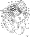
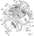
- a brake carrier 10 a floating brake calliper 12 a first brake pad 14 arranged on a first side of a brake disc 13 and a second brake pad 16 arranged on a second side of the brake disc 13.
- the first side is the so-called reaction side
- the second side is the application side.
- the first and the second brake pad 14, 16 are held down by means of a hold-down bracket 18 via hold-down springs 20, 22.
- the hold-down springs 20, 22 rest on back plates 24, 26 of the first and the second brake pad 14, 16, respectively.
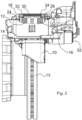
- a spreading device which includes two springs 28, 30, which are supported on two metal sheets 32, 34.
- the springs 28, 30 are helical springs that are subjected to compression.
- the metal sheets 32, 34 are L-shaped.
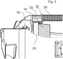
- Figure 3 shows the in Figure 2 left part of the spreading device.
- the spring 30 presses against the sheet 32 to expand, which in turn rests on the hold-down spring 20.
- the hold-down spring 20 is in turn axially coupled to the first brake pad 14 via lugs 36, 38, which is why the restoring force of the springs 28, 30 acts axially on the first brake pad 14.
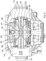
- the design of the spreading device is on the in Figure 2
- the right-hand side is designed symmetrically to the left-hand side, so that the restoring force of the springs 28 and 30 also acts on the second brake pad 16. This restoring force causes the first brake pad 14 and the second brake pad 16 to be moved away from each other, causing them to lift off the brake disc.
- the application device of the brake not shown in the drawing, has a reset device, the application device is reset when the brake is relieved, thereby creating space for the second brake pad 16 on the application side to be lifted off.
- the first brake pad 14 will also lift off, whereby any residual dragging of both the first and the second brake pads 14, 16 on the brake disc is reliably eliminated.
- Figure 4 shows the same detail as Figure 3 , but from an exemplary second embodiment.
- the sheet 32 is not supported on the hold-down spring 20, but rather on the back plate 24.
- the spreading device is designed symmetrically, which is why the sheet 34 is also supported on the back plate 26.
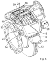
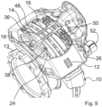
- the Figures 5 and 6 The third exemplary embodiment shown essentially corresponds to the embodiments according to the Figures 1 to 4 , whereby, however, the springs 28, 30 are not as in the Figures 1 to 4 the hold-down bracket 18 or a spoke of the hold-down bracket 18, but rather are arranged next to the hold-down bracket. They are held on the hold-down bracket 18 with brackets 39, 40.
- the brackets 39, 40 can be made in two parts, but they are preferably made in one part.
- the bracket created by this does not necessarily have to be attached to the hold-down bracket 18. Instead, other attachment is also possible.
- the springs 28, 30 can press directly or indirectly on the hold-down springs 20, 22 and/or the back plates 24, 26. This also applies to the embodiments according to the Figures 1 to 4 .
- the spreading device includes two spring wires, which together have approximately the contour of an "X". They are designated with the reference numbers 42, 44. To hold them, they each loop around a spoke of the hold-down bracket 18. At their ends, they are supported on the back plates 24, 26 of the first and second brake pads 14, 16, respectively. In the middle they are supported axially on a common abutment 46. In the middle of the abutment 46 there is a screw 47, which, on the one hand, fixes the abutment 46 on the hold-down bracket 18 and, on the other hand, offers the possibility of specifically adjusting the spring preload on both sides of the brake disc 13. While the springs 28, 30 are subjected to pressure or compression and thus generate the elastic restoring force for expansion, the spring wires 42, 44 are subjected to bending stress. Otherwise, they cause the same spread as the springs 28, 30.
- the screw 47 can be used to specifically adjust the position of the abutment 46, which encloses the hold-down bracket 18.
- the abutment 46 is positioned frictionally on the hold-down bracket 18. If the abutment 46 is positioned off-center and fixed with the screw 47, different spring preloads occur on the application side on the one hand and on the reaction side on the other. So there is a deliberately adjusted power imbalance. With a positive connection between the abutment 46 and the hold-down bracket 18, a balance of forces, i.e. the same spring preload on both sides, is achieved, which, however, leads to an imbalance of forces due to the displacement of the brake caliper 12 when the pads wear.
- the springs 48, 50 belonging to the spreading device are subjected partly to bending and partly to pressure in order to generate the restoring force used for spreading. They wrap around the spokes of the hold-down bracket 18 several times. At their ends they are supported on projections of the back plates 24, 26, two of which are designated with the reference numbers 36, 38, see also Figure 1 .
Landscapes
- Engineering & Computer Science (AREA)
- General Engineering & Computer Science (AREA)
- Mechanical Engineering (AREA)
- Transportation (AREA)
- Braking Arrangements (AREA)
Applications Claiming Priority (2)
| Application Number | Priority Date | Filing Date | Title |
|---|---|---|---|
| DE102016004516.7A DE102016004516A1 (de) | 2016-04-13 | 2016-04-13 | Scheibenbremse, insbesondere für Nutzfahrzeuge |
| PCT/EP2017/000412 WO2017178096A1 (de) | 2016-04-13 | 2017-04-04 | Scheibenbremse, insbesondere für nutzfahrzeuge |
Publications (3)
| Publication Number | Publication Date |
|---|---|
| EP3443239A1 EP3443239A1 (de) | 2019-02-20 |
| EP3443239B1 EP3443239B1 (de) | 2021-01-06 |
| EP3443239B2 true EP3443239B2 (de) | 2024-04-03 |
Family
ID=58549111
Family Applications (1)
| Application Number | Title | Priority Date | Filing Date |
|---|---|---|---|
| EP17718019.7A Active EP3443239B2 (de) | 2016-04-13 | 2017-04-04 | Scheibenbremse, insbesondere für nutzfahrzeuge |
Country Status (5)
| Country | Link |
|---|---|
| US (2) | US10837506B2 (zh) |
| EP (1) | EP3443239B2 (zh) |
| CN (1) | CN108779820B (zh) |
| DE (1) | DE102016004516A1 (zh) |
| WO (1) | WO2017178096A1 (zh) |
Families Citing this family (10)
| Publication number | Priority date | Publication date | Assignee | Title |
|---|---|---|---|---|
| DE102015118838A1 (de) * | 2015-11-03 | 2017-05-04 | Knorr-Bremse Systeme für Nutzfahrzeuge GmbH | Scheibenbremse mit Belaghaltebügel und Sicherungsvorrichtung, und Bremsbelagsatz |
| DE102016120481A1 (de) * | 2016-10-27 | 2018-05-03 | Knorr-Bremse Systeme für Nutzfahrzeuge GmbH | Scheibenbremse für ein Nutzfahrzeug und Bremsbelagsatz |
| WO2019223862A1 (de) * | 2018-05-23 | 2019-11-28 | Wabco Europe Bvba | Richtungspfeil am bremsenträger |
| CN117605774A (zh) | 2018-12-18 | 2024-02-27 | 沃尔沃卡车集团 | 车轮制动装置 |
| CN109667854B (zh) * | 2018-12-20 | 2024-02-13 | 上海韩东机械科技有限公司 | 摩擦制动器 |
| US20220290727A1 (en) * | 2019-09-02 | 2022-09-15 | Volvo Truck Corporation | Brake pad retainer arrangement |
| DE102019131840A1 (de) * | 2019-11-25 | 2021-05-27 | Knorr-Bremse Systeme für Nutzfahrzeuge GmbH | Scheibenbremse für ein Nutzfahrzeug |
| CN111089128A (zh) * | 2019-12-30 | 2020-05-01 | 武汉万向汽车制动器有限公司 | 摩擦片主动回位机构 |
| GB2603821B (en) * | 2021-06-10 | 2023-06-28 | Mei Brakes Ltd | Air disc brake for a road vehicle |
| DE102021121995A1 (de) | 2021-08-25 | 2023-03-02 | Zf Cv Systems Europe Bv | Scheibenbremse für ein Kraftfahrzeug |
Citations (4)
| Publication number | Priority date | Publication date | Assignee | Title |
|---|---|---|---|---|
| DE4430956A1 (de) † | 1994-08-31 | 1996-03-07 | Teves Gmbh Alfred | Spreizfeder für Scheibenbremse |
| US20040256183A1 (en) † | 2002-06-28 | 2004-12-23 | Manuel Barbosa | Disc brake having improved pad clip and pad return spring |
| US20160003315A1 (en) † | 2012-12-20 | 2016-01-07 | Freni Brembo S.P.A. | Caliper for disc brake |
| WO2016202778A1 (de) † | 2015-06-15 | 2016-12-22 | Knorr-Bremse Systeme für Nutzfahrzeuge GmbH | Scheibenbremse für ein nutzfahrzeug und bremsbelagsatz |
Family Cites Families (36)
| Publication number | Priority date | Publication date | Assignee | Title |
|---|---|---|---|---|
| IT454367A (zh) * | 1949-01-21 | |||
| US3243017A (en) * | 1964-07-02 | 1966-03-29 | Gen Motors Corp | Hydraulically operable disc brakes for motor vehicles |
| US3376959A (en) * | 1966-09-06 | 1968-04-09 | Bendix Corp | Automatic brake adjuster mechanism |
| US3497036A (en) * | 1966-11-15 | 1970-02-24 | Teves Gmbh Alfred | Wheel-brake cylinder with piston-stop means |
| DE1905576C3 (de) * | 1969-02-05 | 1979-07-26 | Alfred Teves Gmbh, 6000 Frankfurt | Teilbelagscheibenbremse, insbesondere für Kraftfahrzeuge |
| JPS5536687A (en) * | 1978-09-08 | 1980-03-14 | Aisin Seiki Co Ltd | Disc brake |
| DE2844470A1 (de) * | 1978-10-12 | 1980-04-24 | Teves Gmbh Alfred | Scheibenbremse |
| US4382491A (en) * | 1980-08-11 | 1983-05-10 | Hurst Performance, Inc. | Drag free disc brake assembly having automatically adjusting caliper |
| DE3108113A1 (de) * | 1981-03-04 | 1982-09-16 | FAG Kugelfischer Georg Schäfer & Co, 8720 Schweinfurt | Teilbelagscheibenbremse |
| EP0076202A1 (fr) * | 1981-09-25 | 1983-04-06 | Bendiberica S.A. | Frein à disque à étrier supporté à déplacement axial sur un support fixe |
| US4436186A (en) * | 1981-10-02 | 1984-03-13 | The Bendix Corporation | Disc brake assembly |
| DE3403297A1 (de) * | 1984-01-31 | 1985-08-01 | Deutsche Perrot-Bremse Gmbh, 6800 Mannheim | Gleitsattel-scheibenbremse |
| DE8611037U1 (de) * | 1986-04-22 | 1987-08-20 | Lucas Industries P.L.C., Birmingham, West Midlands | Scheibenbremse, insbesondere für Kraftfahrzeuge |
| FR2616186B1 (fr) * | 1987-06-02 | 1990-10-19 | Bendix France | Ressort pour frein a disque et frein a disque equipe d'un tel ressort |
| DE4131130B4 (de) * | 1990-11-13 | 2005-02-03 | Continental Teves Ag & Co. Ohg | Teilbelagscheibenbremse und Bremsklotz |
| DE4119928C2 (de) * | 1991-06-17 | 2000-11-30 | Perrot Bremse Gmbh Deutsche | Gleitsattel-Scheibenbremse mit Rückstelleinrichtung |
| DE4304616A1 (de) * | 1993-02-16 | 1994-08-18 | Daimler Benz Ag | Scheibenbremse für die Räder eines Kraftfahrzeuges |
| JPH09210104A (ja) * | 1996-01-31 | 1997-08-12 | Akebono Brake Ind Co Ltd | ディスクブレーキのラトルスプリング |
| JPH09329164A (ja) * | 1996-04-08 | 1997-12-22 | Aisin Seiki Co Ltd | ディスクブレーキ |
| US5875873A (en) * | 1997-05-05 | 1999-03-02 | Meritor Heavy Vehicle Systems, Llc | Air disc brake anti-rattle design |
| ATE359453T1 (de) * | 2000-04-18 | 2007-05-15 | Freni Brembo Spa | Eine scheibenbremseinheit |
| US6920965B2 (en) * | 2000-10-18 | 2005-07-26 | Continental Teves Ag & Co. Ohg | Spot-type disc brake with a spring assembly for a brake pad |
| JP4210607B2 (ja) * | 2004-02-06 | 2009-01-21 | 株式会社Tbk | ディスクブレーキのフローティング構造 |
| SE527335C2 (sv) * | 2004-07-01 | 2006-02-14 | Haldex Brake Prod Ab | Stabiliserande element för bromsskiva |
| US20080296104A1 (en) * | 2007-05-31 | 2008-12-04 | Chester Wen | Brake clamping assembly |
| DE102007036353B3 (de) * | 2007-08-02 | 2009-02-26 | Wabco Radbremsen Gmbh | Scheibenbremse, insbesondere für Nutzfahrzeuge, sowie Niederhaltefeder einer solchen Scheibenbremse |
| DE102008010570B3 (de) * | 2008-02-22 | 2009-10-29 | Knorr-Bremse Systeme für Nutzfahrzeuge GmbH | Bremsbelag für eine Scheibenbremse |
| US8393441B2 (en) * | 2011-01-24 | 2013-03-12 | Akebono Brake Corporation | Spreader spring |
| JP2012189188A (ja) * | 2011-03-14 | 2012-10-04 | Akebono Brake Ind Co Ltd | ディスクブレーキ用パッドの戻し装置 |
| US20130048444A1 (en) * | 2011-08-25 | 2013-02-28 | Shimano Inc. | Bicycle disc brake caliper |
| DE102011115304B3 (de) * | 2011-09-29 | 2013-02-07 | Wabco Radbremsen Gmbh | Scheibenbremse, insbesondere für Nutzfahrzeuge, sowie Niederhaltefeder einer solchen Scheibenbremse |
| DE102012102585B4 (de) | 2012-03-26 | 2014-07-10 | Knorr-Bremse Systeme für Nutzfahrzeuge GmbH | Scheibenbremse für ein Nutzfahrzeug |
| DE102012006083A1 (de) * | 2012-03-26 | 2013-09-26 | Knorr-Bremse Systeme für Nutzfahrzeuge GmbH | Scheibenbremse, insbesondere für ein Nutzfahrzeug |
| DE102012023813A1 (de) * | 2012-12-05 | 2014-06-05 | Wabco Radbremsen Gmbh | Scheibenbremse, insbesondere für Nutzfahrzeuge, sowie Niederhaltefeder einer solchen Scheibenbremse |
| US20150001010A1 (en) * | 2013-06-26 | 2015-01-01 | Chih-Hsien Liao | Electric parking caliper |
| US9309938B2 (en) * | 2014-04-23 | 2016-04-12 | Shimano Inc. | Bicycle brake caliper assembly |
-
2016
- 2016-04-13 DE DE102016004516.7A patent/DE102016004516A1/de active Pending
-
2017
- 2017-04-04 CN CN201780015886.9A patent/CN108779820B/zh active Active
- 2017-04-04 US US16/078,410 patent/US10837506B2/en active Active
- 2017-04-04 WO PCT/EP2017/000412 patent/WO2017178096A1/de active Application Filing
- 2017-04-04 EP EP17718019.7A patent/EP3443239B2/de active Active
-
2020
- 2020-11-16 US US17/098,945 patent/US11913507B2/en active Active
Patent Citations (5)
| Publication number | Priority date | Publication date | Assignee | Title |
|---|---|---|---|---|
| DE4430956A1 (de) † | 1994-08-31 | 1996-03-07 | Teves Gmbh Alfred | Spreizfeder für Scheibenbremse |
| US20040256183A1 (en) † | 2002-06-28 | 2004-12-23 | Manuel Barbosa | Disc brake having improved pad clip and pad return spring |
| US20160003315A1 (en) † | 2012-12-20 | 2016-01-07 | Freni Brembo S.P.A. | Caliper for disc brake |
| WO2016202778A1 (de) † | 2015-06-15 | 2016-12-22 | Knorr-Bremse Systeme für Nutzfahrzeuge GmbH | Scheibenbremse für ein nutzfahrzeug und bremsbelagsatz |
| EP3308047B1 (de) † | 2015-06-15 | 2021-01-20 | KNORR-BREMSE Systeme für Nutzfahrzeuge GmbH | Scheibenbremse für ein nutzfahrzeug und bremsbelagsatz |
Also Published As
| Publication number | Publication date |
|---|---|
| WO2017178096A1 (de) | 2017-10-19 |
| EP3443239B1 (de) | 2021-01-06 |
| EP3443239A1 (de) | 2019-02-20 |
| US11913507B2 (en) | 2024-02-27 |
| US10837506B2 (en) | 2020-11-17 |
| CN108779820B (zh) | 2021-03-12 |
| US20190056000A1 (en) | 2019-02-21 |
| US20210062876A1 (en) | 2021-03-04 |
| CN108779820A (zh) | 2018-11-09 |
| DE102016004516A1 (de) | 2017-10-19 |
Similar Documents
| Publication | Publication Date | Title |
|---|---|---|
| EP3443239B2 (de) | Scheibenbremse, insbesondere für nutzfahrzeuge | |
| EP2118512B1 (de) | Scheibenbremse, insbesondere für ein nutzfahrzeug | |
| DE602004000189T2 (de) | Scheibenbremsbelaghalterung | |
| DE602005003600T2 (de) | Scheibenbremse für Fahrzeug | |
| EP2831457B1 (de) | Bremsbelaganordnung für eine schiebesattel-scheibenbremse | |
| DE1725004B1 (de) | Bremsbackenfuehrung fuer eine hydraulisch betaetigbare Teilbelagscheibenbremse | |
| EP3245417B1 (de) | Pneumatisch oder elektromechanisch betätigte scheibenbremse für nutzfahrzeuge | |
| DE102017007288A1 (de) | Bremssattelanordnung mit Belagrückstellfunktion | |
| DE2149413A1 (de) | Bewegungsdaempfer | |
| DE2738582C2 (de) | Bremsbackenführung für eine Teilbelag-Scheibenbremse | |
| WO2018054600A1 (de) | Dämpfventil für einen schwingungsdämpfer | |
| DE102012213274A1 (de) | Scheibenbremse | |
| DE2230949B2 (de) | Bremsbackenführung für eine Teilbelag-Scheibenbremse | |
| DE2211453A1 (de) | Schwimmsattel Scheibenbremse | |
| WO2020208194A1 (de) | Vorrichtung zur rückstellung von bremsbelägen und scheibenbremse | |
| DE102007029927A1 (de) | Scheibenbremse für ein Kraftfahrzeug und Gehäuse hierfür | |
| DE2222945C3 (de) | Vorrichtung zur Befestigung der beiden Haltestifte ffir die Bremsbacken einer Schwimmrahmen-Scheibenbremse | |
| DE1425228A1 (de) | Scheibenbremse | |
| EP3623507B1 (de) | Kettbaumanordnung | |
| DE102016213218B4 (de) | Kupplungseinrichtung | |
| EP1915547A1 (de) | Scheibenbremse, insbesondere für ein nutzfahrzeug | |
| DE1775989B1 (de) | Bremsbackenlagerung fuer innenbackenbremsen mit zwei nebeneinanderliegenden bremsbackenpaaren | |
| DE4343737B4 (de) | Scheibenbremse | |
| DE102010050099A1 (de) | Scheibenbremse mit einer Selbstverstärkungseinrichtung | |
| DE102007024578B3 (de) | Scheibenbremse, insbesondere für Nutzfahrzeuge |
Legal Events
| Date | Code | Title | Description |
|---|---|---|---|
| STAA | Information on the status of an ep patent application or granted ep patent |
Free format text: STATUS: UNKNOWN |
|
| STAA | Information on the status of an ep patent application or granted ep patent |
Free format text: STATUS: THE INTERNATIONAL PUBLICATION HAS BEEN MADE |
|
| PUAI | Public reference made under article 153(3) epc to a published international application that has entered the european phase |
Free format text: ORIGINAL CODE: 0009012 |
|
| STAA | Information on the status of an ep patent application or granted ep patent |
Free format text: STATUS: REQUEST FOR EXAMINATION WAS MADE |
|
| 17P | Request for examination filed |
Effective date: 20181113 |
|
| AK | Designated contracting states |
Kind code of ref document: A1 Designated state(s): AL AT BE BG CH CY CZ DE DK EE ES FI FR GB GR HR HU IE IS IT LI LT LU LV MC MK MT NL NO PL PT RO RS SE SI SK SM TR |
|
| AX | Request for extension of the european patent |
Extension state: BA ME |
|
| DAV | Request for validation of the european patent (deleted) | ||
| DAX | Request for extension of the european patent (deleted) | ||
| STAA | Information on the status of an ep patent application or granted ep patent |
Free format text: STATUS: EXAMINATION IS IN PROGRESS |
|
| 17Q | First examination report despatched |
Effective date: 20191113 |
|
| GRAP | Despatch of communication of intention to grant a patent |
Free format text: ORIGINAL CODE: EPIDOSNIGR1 |
|
| STAA | Information on the status of an ep patent application or granted ep patent |
Free format text: STATUS: GRANT OF PATENT IS INTENDED |
|
| INTG | Intention to grant announced |
Effective date: 20200918 |
|
| GRAS | Grant fee paid |
Free format text: ORIGINAL CODE: EPIDOSNIGR3 |
|
| GRAA | (expected) grant |
Free format text: ORIGINAL CODE: 0009210 |
|
| STAA | Information on the status of an ep patent application or granted ep patent |
Free format text: STATUS: THE PATENT HAS BEEN GRANTED |
|
| AK | Designated contracting states |
Kind code of ref document: B1 Designated state(s): AL AT BE BG CH CY CZ DE DK EE ES FI FR GB GR HR HU IE IS IT LI LT LU LV MC MK MT NL NO PL PT RO RS SE SI SK SM TR |
|
| REG | Reference to a national code |
Ref country code: GB Ref legal event code: FG4D Free format text: NOT ENGLISH |
|
| REG | Reference to a national code |
Ref country code: AT Ref legal event code: REF Ref document number: 1352704 Country of ref document: AT Kind code of ref document: T Effective date: 20210115 Ref country code: CH Ref legal event code: EP |
|
| REG | Reference to a national code |
Ref country code: DE Ref legal event code: R096 Ref document number: 502017008951 Country of ref document: DE |
|
| REG | Reference to a national code |
Ref country code: IE Ref legal event code: FG4D Free format text: LANGUAGE OF EP DOCUMENT: GERMAN |
|
| RAP4 | Party data changed (patent owner data changed or rights of a patent transferred) |
Owner name: ZF CV SYSTEMS EUROPE BV |
|
| REG | Reference to a national code |
Ref country code: NL Ref legal event code: MP Effective date: 20210106 |
|
| REG | Reference to a national code |
Ref country code: LT Ref legal event code: MG9D |
|
| PG25 | Lapsed in a contracting state [announced via postgrant information from national office to epo] |
Ref country code: PT Free format text: LAPSE BECAUSE OF FAILURE TO SUBMIT A TRANSLATION OF THE DESCRIPTION OR TO PAY THE FEE WITHIN THE PRESCRIBED TIME-LIMIT Effective date: 20210506 Ref country code: NO Free format text: LAPSE BECAUSE OF FAILURE TO SUBMIT A TRANSLATION OF THE DESCRIPTION OR TO PAY THE FEE WITHIN THE PRESCRIBED TIME-LIMIT Effective date: 20210406 Ref country code: FI Free format text: LAPSE BECAUSE OF FAILURE TO SUBMIT A TRANSLATION OF THE DESCRIPTION OR TO PAY THE FEE WITHIN THE PRESCRIBED TIME-LIMIT Effective date: 20210106 Ref country code: HR Free format text: LAPSE BECAUSE OF FAILURE TO SUBMIT A TRANSLATION OF THE DESCRIPTION OR TO PAY THE FEE WITHIN THE PRESCRIBED TIME-LIMIT Effective date: 20210106 Ref country code: GR Free format text: LAPSE BECAUSE OF FAILURE TO SUBMIT A TRANSLATION OF THE DESCRIPTION OR TO PAY THE FEE WITHIN THE PRESCRIBED TIME-LIMIT Effective date: 20210407 Ref country code: LT Free format text: LAPSE BECAUSE OF FAILURE TO SUBMIT A TRANSLATION OF THE DESCRIPTION OR TO PAY THE FEE WITHIN THE PRESCRIBED TIME-LIMIT Effective date: 20210106 Ref country code: BG Free format text: LAPSE BECAUSE OF FAILURE TO SUBMIT A TRANSLATION OF THE DESCRIPTION OR TO PAY THE FEE WITHIN THE PRESCRIBED TIME-LIMIT Effective date: 20210406 |
|
| PG25 | Lapsed in a contracting state [announced via postgrant information from national office to epo] |
Ref country code: LV Free format text: LAPSE BECAUSE OF FAILURE TO SUBMIT A TRANSLATION OF THE DESCRIPTION OR TO PAY THE FEE WITHIN THE PRESCRIBED TIME-LIMIT Effective date: 20210106 Ref country code: PL Free format text: LAPSE BECAUSE OF FAILURE TO SUBMIT A TRANSLATION OF THE DESCRIPTION OR TO PAY THE FEE WITHIN THE PRESCRIBED TIME-LIMIT Effective date: 20210106 Ref country code: RS Free format text: LAPSE BECAUSE OF FAILURE TO SUBMIT A TRANSLATION OF THE DESCRIPTION OR TO PAY THE FEE WITHIN THE PRESCRIBED TIME-LIMIT Effective date: 20210106 Ref country code: SE Free format text: LAPSE BECAUSE OF FAILURE TO SUBMIT A TRANSLATION OF THE DESCRIPTION OR TO PAY THE FEE WITHIN THE PRESCRIBED TIME-LIMIT Effective date: 20210106 |
|
| REG | Reference to a national code |
Ref country code: DE Ref legal event code: R081 Ref document number: 502017008951 Country of ref document: DE Owner name: ZF CV SYSTEMS EUROPE BV, BE Free format text: FORMER OWNER: WABCO EUROPE BVBA, BRUSSELS, BE |
|
| PG25 | Lapsed in a contracting state [announced via postgrant information from national office to epo] |
Ref country code: IS Free format text: LAPSE BECAUSE OF FAILURE TO SUBMIT A TRANSLATION OF THE DESCRIPTION OR TO PAY THE FEE WITHIN THE PRESCRIBED TIME-LIMIT Effective date: 20210506 |
|
| REG | Reference to a national code |
Ref country code: DE Ref legal event code: R026 Ref document number: 502017008951 Country of ref document: DE |
|
| PLBI | Opposition filed |
Free format text: ORIGINAL CODE: 0009260 |
|
| PLAX | Notice of opposition and request to file observation + time limit sent |
Free format text: ORIGINAL CODE: EPIDOSNOBS2 |
|
| PG25 | Lapsed in a contracting state [announced via postgrant information from national office to epo] |
Ref country code: SM Free format text: LAPSE BECAUSE OF FAILURE TO SUBMIT A TRANSLATION OF THE DESCRIPTION OR TO PAY THE FEE WITHIN THE PRESCRIBED TIME-LIMIT Effective date: 20210106 Ref country code: EE Free format text: LAPSE BECAUSE OF FAILURE TO SUBMIT A TRANSLATION OF THE DESCRIPTION OR TO PAY THE FEE WITHIN THE PRESCRIBED TIME-LIMIT Effective date: 20210106 Ref country code: CZ Free format text: LAPSE BECAUSE OF FAILURE TO SUBMIT A TRANSLATION OF THE DESCRIPTION OR TO PAY THE FEE WITHIN THE PRESCRIBED TIME-LIMIT Effective date: 20210106 |
|
| 26 | Opposition filed |
Opponent name: KNORR-BREMSE SYSTEME FUER NUTZFAHRZEUGE GMBH Effective date: 20211005 |
|
| PG25 | Lapsed in a contracting state [announced via postgrant information from national office to epo] |
Ref country code: MC Free format text: LAPSE BECAUSE OF FAILURE TO SUBMIT A TRANSLATION OF THE DESCRIPTION OR TO PAY THE FEE WITHIN THE PRESCRIBED TIME-LIMIT Effective date: 20210106 Ref country code: DK Free format text: LAPSE BECAUSE OF FAILURE TO SUBMIT A TRANSLATION OF THE DESCRIPTION OR TO PAY THE FEE WITHIN THE PRESCRIBED TIME-LIMIT Effective date: 20210106 Ref country code: SK Free format text: LAPSE BECAUSE OF FAILURE TO SUBMIT A TRANSLATION OF THE DESCRIPTION OR TO PAY THE FEE WITHIN THE PRESCRIBED TIME-LIMIT Effective date: 20210106 Ref country code: RO Free format text: LAPSE BECAUSE OF FAILURE TO SUBMIT A TRANSLATION OF THE DESCRIPTION OR TO PAY THE FEE WITHIN THE PRESCRIBED TIME-LIMIT Effective date: 20210106 |
|
| PG25 | Lapsed in a contracting state [announced via postgrant information from national office to epo] |
Ref country code: LU Free format text: LAPSE BECAUSE OF NON-PAYMENT OF DUE FEES Effective date: 20210404 |
|
| REG | Reference to a national code |
Ref country code: BE Ref legal event code: MM Effective date: 20210430 |
|
| PG25 | Lapsed in a contracting state [announced via postgrant information from national office to epo] |
Ref country code: LI Free format text: LAPSE BECAUSE OF NON-PAYMENT OF DUE FEES Effective date: 20210430 Ref country code: AL Free format text: LAPSE BECAUSE OF FAILURE TO SUBMIT A TRANSLATION OF THE DESCRIPTION OR TO PAY THE FEE WITHIN THE PRESCRIBED TIME-LIMIT Effective date: 20210106 Ref country code: CH Free format text: LAPSE BECAUSE OF NON-PAYMENT OF DUE FEES Effective date: 20210430 Ref country code: ES Free format text: LAPSE BECAUSE OF FAILURE TO SUBMIT A TRANSLATION OF THE DESCRIPTION OR TO PAY THE FEE WITHIN THE PRESCRIBED TIME-LIMIT Effective date: 20210106 |
|
| PG25 | Lapsed in a contracting state [announced via postgrant information from national office to epo] |
Ref country code: SI Free format text: LAPSE BECAUSE OF FAILURE TO SUBMIT A TRANSLATION OF THE DESCRIPTION OR TO PAY THE FEE WITHIN THE PRESCRIBED TIME-LIMIT Effective date: 20210106 |
|
| PLBB | Reply of patent proprietor to notice(s) of opposition received |
Free format text: ORIGINAL CODE: EPIDOSNOBS3 |
|
| PG25 | Lapsed in a contracting state [announced via postgrant information from national office to epo] |
Ref country code: IT Free format text: LAPSE BECAUSE OF FAILURE TO SUBMIT A TRANSLATION OF THE DESCRIPTION OR TO PAY THE FEE WITHIN THE PRESCRIBED TIME-LIMIT Effective date: 20210106 Ref country code: IE Free format text: LAPSE BECAUSE OF NON-PAYMENT OF DUE FEES Effective date: 20210404 |
|
| PG25 | Lapsed in a contracting state [announced via postgrant information from national office to epo] |
Ref country code: IS Free format text: LAPSE BECAUSE OF FAILURE TO SUBMIT A TRANSLATION OF THE DESCRIPTION OR TO PAY THE FEE WITHIN THE PRESCRIBED TIME-LIMIT Effective date: 20210506 |
|
| PG25 | Lapsed in a contracting state [announced via postgrant information from national office to epo] |
Ref country code: BE Free format text: LAPSE BECAUSE OF NON-PAYMENT OF DUE FEES Effective date: 20210430 |
|
| REG | Reference to a national code |
Ref country code: AT Ref legal event code: MM01 Ref document number: 1352704 Country of ref document: AT Kind code of ref document: T Effective date: 20220404 |
|
| PG25 | Lapsed in a contracting state [announced via postgrant information from national office to epo] |
Ref country code: NL Free format text: LAPSE BECAUSE OF NON-PAYMENT OF DUE FEES Effective date: 20210206 Ref country code: CY Free format text: LAPSE BECAUSE OF FAILURE TO SUBMIT A TRANSLATION OF THE DESCRIPTION OR TO PAY THE FEE WITHIN THE PRESCRIBED TIME-LIMIT Effective date: 20210106 |
|
| P01 | Opt-out of the competence of the unified patent court (upc) registered |
Effective date: 20230528 |
|
| PG25 | Lapsed in a contracting state [announced via postgrant information from national office to epo] |
Ref country code: HU Free format text: LAPSE BECAUSE OF FAILURE TO SUBMIT A TRANSLATION OF THE DESCRIPTION OR TO PAY THE FEE WITHIN THE PRESCRIBED TIME-LIMIT; INVALID AB INITIO Effective date: 20170404 Ref country code: AT Free format text: LAPSE BECAUSE OF NON-PAYMENT OF DUE FEES Effective date: 20220404 |
|
| PUAH | Patent maintained in amended form |
Free format text: ORIGINAL CODE: 0009272 |
|
| STAA | Information on the status of an ep patent application or granted ep patent |
Free format text: STATUS: PATENT MAINTAINED AS AMENDED |
|
| 27A | Patent maintained in amended form |
Effective date: 20240403 |
|
| AK | Designated contracting states |
Kind code of ref document: B2 Designated state(s): AL AT BE BG CH CY CZ DE DK EE ES FI FR GB GR HR HU IE IS IT LI LT LU LV MC MK MT NL NO PL PT RO RS SE SI SK SM TR |
|
| REG | Reference to a national code |
Ref country code: DE Ref legal event code: R102 Ref document number: 502017008951 Country of ref document: DE |
|
| PG25 | Lapsed in a contracting state [announced via postgrant information from national office to epo] |
Ref country code: MK Free format text: LAPSE BECAUSE OF FAILURE TO SUBMIT A TRANSLATION OF THE DESCRIPTION OR TO PAY THE FEE WITHIN THE PRESCRIBED TIME-LIMIT Effective date: 20210106 |
|
| PGFP | Annual fee paid to national office [announced via postgrant information from national office to epo] |
Ref country code: GB Payment date: 20240229 Year of fee payment: 8 |
|
| PGFP | Annual fee paid to national office [announced via postgrant information from national office to epo] |
Ref country code: FR Payment date: 20240308 Year of fee payment: 8 |
|
| PGFP | Annual fee paid to national office [announced via postgrant information from national office to epo] |
Ref country code: DE Payment date: 20240306 Year of fee payment: 8 |