EP3443177B1 - Vorrichtung zum abdecken und freilegen einer oberfläche mit gekoppelten selbstfahrenden einstellbaren lamellen - Google Patents
Vorrichtung zum abdecken und freilegen einer oberfläche mit gekoppelten selbstfahrenden einstellbaren lamellen Download PDFInfo
- Publication number
- EP3443177B1 EP3443177B1 EP17722097.7A EP17722097A EP3443177B1 EP 3443177 B1 EP3443177 B1 EP 3443177B1 EP 17722097 A EP17722097 A EP 17722097A EP 3443177 B1 EP3443177 B1 EP 3443177B1
- Authority
- EP
- European Patent Office
- Prior art keywords
- slat
- slats
- carriage
- blade
- blades
- Prior art date
- Legal status (The legal status is an assumption and is not a legal conclusion. Google has not performed a legal analysis and makes no representation as to the accuracy of the status listed.)
- Active
Links
- 238000009434 installation Methods 0.000 claims description 68
- 230000007246 mechanism Effects 0.000 claims description 44
- 230000008878 coupling Effects 0.000 claims description 25
- 238000010168 coupling process Methods 0.000 claims description 25
- 238000005859 coupling reaction Methods 0.000 claims description 25
- 230000009471 action Effects 0.000 claims description 9
- 238000011144 upstream manufacturing Methods 0.000 claims description 7
- 230000001131 transforming effect Effects 0.000 claims description 3
- 230000009466 transformation Effects 0.000 claims description 2
- 238000006073 displacement reaction Methods 0.000 description 72
- 238000005192 partition Methods 0.000 description 5
- 101100536354 Drosophila melanogaster tant gene Proteins 0.000 description 4
- 230000001681 protective effect Effects 0.000 description 4
- 230000001360 synchronised effect Effects 0.000 description 3
- 208000031968 Cadaver Diseases 0.000 description 2
- 241000946381 Timon Species 0.000 description 2
- 238000010586 diagram Methods 0.000 description 2
- 238000005452 bending Methods 0.000 description 1
- 230000008901 benefit Effects 0.000 description 1
- 230000005540 biological transmission Effects 0.000 description 1
- 230000000903 blocking effect Effects 0.000 description 1
- 230000008859 change Effects 0.000 description 1
- 230000005489 elastic deformation Effects 0.000 description 1
- 238000001125 extrusion Methods 0.000 description 1
- 238000004519 manufacturing process Methods 0.000 description 1
- 238000000034 method Methods 0.000 description 1
- 238000012986 modification Methods 0.000 description 1
- 230000004048 modification Effects 0.000 description 1
- 230000007935 neutral effect Effects 0.000 description 1
- 230000008569 process Effects 0.000 description 1
- 238000009423 ventilation Methods 0.000 description 1
Images


Classifications
-
- E—FIXED CONSTRUCTIONS
- E04—BUILDING
- E04F—FINISHING WORK ON BUILDINGS, e.g. STAIRS, FLOORS
- E04F10/00—Sunshades, e.g. Florentine blinds or jalousies; Outside screens; Awnings or baldachins
- E04F10/08—Sunshades, e.g. Florentine blinds or jalousies; Outside screens; Awnings or baldachins of a plurality of similar rigid parts, e.g. slabs, lamellae
- E04F10/10—Sunshades, e.g. Florentine blinds or jalousies; Outside screens; Awnings or baldachins of a plurality of similar rigid parts, e.g. slabs, lamellae collapsible or extensible; metallic Florentine blinds; awnings with movable parts such as louvres
-
- E—FIXED CONSTRUCTIONS
- E04—BUILDING
- E04B—GENERAL BUILDING CONSTRUCTIONS; WALLS, e.g. PARTITIONS; ROOFS; FLOORS; CEILINGS; INSULATION OR OTHER PROTECTION OF BUILDINGS
- E04B7/00—Roofs; Roof construction with regard to insulation
- E04B7/16—Roof structures with movable roof parts
- E04B7/163—Roof structures with movable roof parts characterised by a pivoting movement of the movable roof parts
-
- E—FIXED CONSTRUCTIONS
- E04—BUILDING
- E04B—GENERAL BUILDING CONSTRUCTIONS; WALLS, e.g. PARTITIONS; ROOFS; FLOORS; CEILINGS; INSULATION OR OTHER PROTECTION OF BUILDINGS
- E04B7/00—Roofs; Roof construction with regard to insulation
- E04B7/16—Roof structures with movable roof parts
- E04B7/166—Roof structures with movable roof parts characterised by a translation movement of the movable roof part, with or without additional movements
-
- E—FIXED CONSTRUCTIONS
- E06—DOORS, WINDOWS, SHUTTERS, OR ROLLER BLINDS IN GENERAL; LADDERS
- E06B—FIXED OR MOVABLE CLOSURES FOR OPENINGS IN BUILDINGS, VEHICLES, FENCES OR LIKE ENCLOSURES IN GENERAL, e.g. DOORS, WINDOWS, BLINDS, GATES
- E06B7/00—Special arrangements or measures in connection with doors or windows
- E06B7/02—Special arrangements or measures in connection with doors or windows for providing ventilation, e.g. through double windows; Arrangement of ventilation roses
- E06B7/08—Louvre doors, windows or grilles
- E06B7/084—Louvre doors, windows or grilles with rotatable lamellae
- E06B7/086—Louvre doors, windows or grilles with rotatable lamellae interconnected for concurrent movement
- E06B7/092—Louvre doors, windows or grilles with rotatable lamellae interconnected for concurrent movement operable in two or more distinct sets
-
- E—FIXED CONSTRUCTIONS
- E06—DOORS, WINDOWS, SHUTTERS, OR ROLLER BLINDS IN GENERAL; LADDERS
- E06B—FIXED OR MOVABLE CLOSURES FOR OPENINGS IN BUILDINGS, VEHICLES, FENCES OR LIKE ENCLOSURES IN GENERAL, e.g. DOORS, WINDOWS, BLINDS, GATES
- E06B7/00—Special arrangements or measures in connection with doors or windows
- E06B7/02—Special arrangements or measures in connection with doors or windows for providing ventilation, e.g. through double windows; Arrangement of ventilation roses
- E06B7/08—Louvre doors, windows or grilles
- E06B7/084—Louvre doors, windows or grilles with rotatable lamellae
- E06B7/086—Louvre doors, windows or grilles with rotatable lamellae interconnected for concurrent movement
- E06B7/096—Louvre doors, windows or grilles with rotatable lamellae interconnected for concurrent movement operated or interconnected by gearing
Definitions
- the present invention relates to the technical field of installations for covering and discovering a surface using orientable blades extending parallel to one another in order to constitute a protective or closing screen for a surface in general, these blades orientable with the possibility in the deployed position relative to the surface, to open or close depending in particular on climatic conditions.
- the object of the invention is aimed at numerous applications for constituting in particular a roof covering forming part of pergolas or terraces for example, or a protective screen for doors or windows.
- this openable roof Compared to a fixed roof which only protects a space from rain and sun, this openable roof also offers the possibility of controlling, at will, the ventilation and sunshine of the space equipped with such a roof .
- this openable roof has the drawback of allowing the adjustable slats to remain permanently above the surface to be covered, which can represent a drawback in particular during a long period of non-sunshine.
- Each orientation and displacement mechanism comprises on the one hand, an external chain or belt mounted endlessly between fixed return pulleys and having an outer strand and an inner strand, and on the other hand, an internal belt mounted without end between fixed return pulleys and having an outer strand and an inner strand which extends opposite the inner strand of the external belt to delimit between them a drive passage for the blades.
- Each orientation and displacement mechanism includes a synchronized motorization system for the external belts and a synchronized motorization system for the internal belts. The motorization of the motorization systems is controlled, on the one hand, to move the internal strands in the same direction to move the blades in translation in the drive corridor and, on the other hand, to move the internal strands in opposite directions to orient the blades.
- Each orientation and displacement mechanism comprises a device for distributing the blades driven by the synchronized motorization systems of the belts and adapted for, in a direction of movement of the strands, successively engaging at a constant spacing pitch, the blades in the driveway and, in an opposite direction of movement, successively disengage the blades from the driveway so that they occupy their stored position.
- This installation is not designed to constitute a roof and in practice proves unsuitable for covering a relatively large opening.
- Another drawback of such an installation relates to the need to provide a storage warehouse for the blades.
- This storage warehouse is arranged either to encroach on the surface to be covered or as an extension of the surface to be covered if a space is available for this purpose.
- the patent EP 1,595,053 describes a mechanism for closing an opening from blades each provided at each of their ends with a nut cooperating with a motorized screw extending over the entire length of the opening.
- the nuts are engaged in a guide rail making it possible to translate the blades during the rotation of the screws.
- This mechanism also includes, at a store for storing the blades in the folded position, a rack cooperating with the nuts in order to distribute the blades in a constant pitch or ensure their stacking in the store.
- each end of the blades is provided with a roller cooperating with a system ensuring the orientation of the blades.
- the patent application WO 2012/107350 describes a thermal shutter installation for window comprising a series of orientable shutters extending parallel to each other, each supported by a guide at each of its ends.
- the installation comprises on both sides of the flaps, threaded rods cooperating with a gearbox fitted to each guide of the flaps.
- the guides of each flap are provided with motors for orienting the flaps and for independently moving the flaps relative to each other.
- the patent EP 2,868,833 describes an installation with orientable and retractable blades comprising at their ends, carriages connected together by deformable structures.
- This train of carriages comprises a master carriage connected by means of an endless transmission member, to a motor of displacement placed on a transverse side of the installation.
- the orientation of the blades is ensured by means of an orientation motor placed on a transverse side of the installation and acting by means of a linkage on the blades.
- Such an installation has a relatively large production complexity and a relatively large size for housing the drive means for rotating and sliding the blades.
- the patent application US 2013/248124 describes a system for controlling the position and orientation of a panel fitted to a window relative to the sun.
- this panel is moved in translation using an electric motor on board the panel and the output pinion of which cooperates with a rack carried by the window frame.
- Such a system is not suitable for covering a surface with the aid of blades which have to be moved in translation and oriented in inclination.
- the present invention aims to remedy the drawbacks of the prior art by proposing an installation of simple design, compact and inexpensive to cover and discover, using orientable blades, a surface as well vertical as horizontal which presents variable dimensions in a wide range up to large dimensions.
- the present invention aims to provide a completely modular installation making it possible to easily adapt to the dimensions of the surface to be covered, while offering the advantage of being able to orient the blades of various areas of the surface at will in different positions.
- Another object of the invention is to propose an installation that does not require dedicating a space for storing the blades in the folded position.
- the displacement system comprises, for each blade of even rank, on the one hand, a retractable hitch fixed between the first carriage of said blade and the first carriage belonging to the head blade or to the neighboring blade of lower rank, and on the other hand a drive system in translation of the second carriage of said blade, and for each blade has an odd rank, a retractable hitch fixed between the second carriage of said blade and the second carriage belonging to the neighboring blade of lower rank and a drive system in translation of the first carriage of said blade.
- the installation comprises displacement sensors for the blades
- the displacement system comprises, for each head blade, motors of displacement embedded in the first and second trolleys, and the displacement motors embedded in the trolleys are connected to transformation of the rotational movement into a translational movement of the blades in a direction parallel to the guideway.
- the object of the invention relates to an installation 1 for covering and discovering a surface 2 by a series of orientable blades 3 extending one behind the other, preferably being all identical and parallel to each other along their longitudinal axis.
- Each adjustable blade 3 has a generally rectangular shape delimited by a first and a second longitudinal edge 3 a and 3 b parallel to each other and connected to each other by first and second end edges 3 c and 3 d parallel also between them.
- the number and dimensions of the adjustable blades are adapted to the dimensions of the rectangular surface 2 to be covered.
- the orientable blades 3 are capable of forming together a screen of rectangular shape delimited on the one hand by the longitudinal edge 3 a of the first blade 3 and by the longitudinal edge 3 b of the last blade 3 and on the other hand, by all of the first end edges 3 c of the blades aligned together and by all of the second end edges 3 d of the blades aligned together.
- the blades 3 are provided at each of their end edges with a pivot axis 4 to allow in particular their orientation.
- the installation 1 includes a mechanism I for orienting the blades 3 along their pivot axis 4 in order to ensure the pivoting of at least some and generally of the assembly of the blades 3 so that the longitudinal edges 3 a , 3 b of the adjacent blades are joined to close the corresponding surface or are not joined to open the surface 2.
- the adjustable blades 3 can thus form in a zone Z 1 , a screen insofar as the longitudinal edges of the blades are joined with the longitudinal edges of the neighboring blades.
- the blades 3 are deployed above the surface in an upright or open position.
- this example of deployment of the blades 3 is given by way of illustration only insofar as the blades 3 can be deployed and oriented according to many other configurations as will be better understood in the following description.
- the installation according to the invention also comprises a system II for moving the blades 3 between a stored position ( Fig. 1 ) and a partially or fully extended position opposite surface 2 ( Fig. 2 and 3 ).
- a system II for moving the blades 3 between a stored position ( Fig. 1 ) and a partially or fully extended position opposite surface 2 ( Fig. 2 and 3 ).
- the blades 3 are placed side by side between a stowed head blade and a storage edge 5 1 of a supporting structure or frame 5.
- the blades 3 cannot be oriented and the blades 3 occupy an upright position, that is to say that the blades are located in parallel planes substantially perpendicular to the surface 2, namely vertical in the example illustrated.
- the installation 1 also includes two guide tracks 8 ensuring the translational guidance for the blades 3 between a stowed position in which the blades are placed side by side ( Fig. 1 ) and a position deployed in which at least part or all of the blades 3 are deployed facing the surface 2 ( Fig. 2 to 4 ) .
- the guide tracks 8 are arranged on the support structure of the frame 5 which is produced in any suitable manner according to the intended applications by coming to surround the surface 2 to be covered to advantageously form a frame.
- This supporting structure 5 advantageously comprises two longitudinal sections 5 2 and 5 3 extending parallel to one another along two opposite longitudinal sides of the surface 2 and parallel to the guide tracks 8. These two longitudinal sections 5 2 and 5 3 are interconnected at their end, by connection profiles 5 1 and 5 4 (not shown) together forming a frame delimiting the surface 2.
- connection profiles 5 4 delimits the abutment edge for the longitudinal edge 3 a of the first blade while the other profile 5 1 delimits the storage edge for the longitudinal edge of the last blade 3.
- the first blade and the last blade are taken into consideration of the direction of deployment of the blades represented by the arrow F for which the blades pass from the stored position to the deployed position.
- the first and last blades are considered to be the same as those designated during the deployment operation.
- the installation comprises a series of orientable blades 3 comprising blades of odd rank 3 1 , 3 3 , 3 5 , ..., 3 i , including the first blade 3 1 which is said to be at the head as this will be explained in the following description.
- This series of blades 3 also includes blades of even rank 3 2 , 3 4 , 3 6 , ..., 3 i + 1 , interposed between the blades of odd rank so as to alternately obtain a blade of even rank followed by a blade of odd rank, with the rank of the blades increasing from the so-called head blade.
- the number of blades of even rank and the number of blades of odd rank which are identical or different from one unit depend on the dimensions of the surface to be covered.
- the installation 1 according to the invention is intended to be fixed by any appropriate means to a support structure, not shown, suitable for the application referred.
- the support structure 5 can be fixed to walls or be equipped with posts supporting the frame formed by the connecting profiles and longitudinal sections.
- each blade 3 is supported at each of its ends more precisely by its pivot axes 4, by a set of two carriages, namely a first carriage 10 1 and a second carriage 10 2 guided in translation according to the guideways 8.
- each blade 3 is therefore supported by its pivot axes 4, using two carriages 10 1 , 10 2 moving in translation along the guide tracks between the stowed position and the deployed position.
- all the first carriages 10 1 of the blades cooperate with the same guide track, that is to say are positioned on the same longitudinal side of the surface 2 while all the second carriages 10 2 of the blades cooperate with the other guide track, that is to say by being positioned on the other longitudinal side of the surface 2.
- each carriage 10 1, 10 2 is provided with a guide system 11 cooperating with a guide track 8.
- the guide system 11 comprises a roller 11 carried by each carriage and cooperating with a groove formed on the support structure 5 and forming the guide track 8.
- the guide system 11 can be produced in a different way.
- the displacement system II comprises for each pair of carriages 10 1 , 10 2 equipping a so-called head blade 3 1 , two displacement motors 12 each on board a different carriage. It should be understood that a blade is said to be a head 3 1 if it is motorized at each of its two ends by a motor to balance the forces applied to the blade.
- the displacement system II comprises a single blade 3 1, called the head blade, each carriage 10 1 , 10 2 of which has a displacement motor 12 ( Fig. 4 , 6 ).
- the displacement system II comprises several so-called head blades 3 1, namely two in the example, each of the carriages 10 1 , 10 2 is equipped with a displacement motor 12. It should be noted that in the case where the displacement system II comprises several blades 3 1 called the head, the blades of odd rank, 3 3 , 3 5 , ..., 3 i , and the blades of even rank 3 2 , 3 4 , 3 6 , ... , 3 i + 1 are considered from each blade 3 1 called the head.
- the displacement system II comprises several blades 3 1 called the head
- the blades of odd rank, 3 3 , 3 5 , ..., 3 i the blades of even rank 3 2 , 3 4 , 3 6 , ... , 3 i + 1 are considered from each blade 3 1 called the head.
- the installation comprises two groups of blades 3 1 , 3 2 , 3 3 , each comprising a so-called head blade 3 1 and a blade of even rank interposed between 2 blades of odd rank, with the row of blades starting and increasing at from each so-called head blade.
- the installation comprises a single group of blades each comprising a single blade called the head 3 1 .
- the displacement system II comprises for each blade of even rank 3 2 , 3 4 , 3 6 , ..., 3 i + 1 , forming part of a group of blades, on the one hand, a retractable hitch A fixed between the first carriage 10 1 of said blade and the first carriage 10 1 belonging to the head blade or to the neighboring blade of lower rank, and on the other hand a drive system in translation S of the second carriage 10 2 of said blade .
- a retractable hitch A is capable of occupying on the one hand a first position known as hitching or towing according to which a mechanical assembly is produced between two neighboring carriages so that the deployment of a carriage in one direction leads to the displacement of the neighboring carriage in the same direction and, on the other hand, a second so-called retraction position according to which the movement of a carriage does not cause the other carriage to move.
- This retractable coupling A is produced between two first carriages 10 1 belonging to two neighboring blades or between two second carriages 10 2 belonging to two equally adjacent blades.
- a retractable hitch A is fixed between the first carriage 10 1 of the row blade 3 2 and the first carriage 10 1 belonging to the head blade 3 1 while a retractable hitch A is fixed between the first carriage 10 1 of the row blade 3 4 and the first carriage 10 1 belonging to the neighboring blade of lower rank, namely 3 3 .
- a retractable hitch A is fixed for each group of blades, between the first carriage 10 1 of the row blade 3 2 and the first carriage 10 1 belonging to the head blade 3 1 .
- a retractable hitch A is fixed between the first carriage 10 1 of each blade of even rank and the first carriage 10 1 belonging to the blade adjacent to lower row.
- each second carriage 10 2 of each of these blades is equipped with a drive system in translation S of the second carriage 10 2 .
- each translational drive system S of a second carriage 10 2 comprises either a displacement motor 12 on board said second carriage ( Fig. 6 ) or a retractable hitch A fixed between the second carriage 10 2 of said blade and the second carriage 10 2 of the neighboring blade of lower rank ( Fig. 7 ).
- each of the second carriages 10 2 of the blades of even rank 3 2 , 3 4 is equipped as a drive system in translation S, with a displacement motor 12 embedded in each of said carriages 10 2 .
- each of the second carriages 10 2 of the even row blades 3 2 of each group of blades is equipped as a drive system in translation S, with a retractable hitch A fixed between the second carriage 10 2 of said row blade even 3 2 and the second carriage 10 2 of the neighboring blade of lower rank, namely the head blade.
- a retractable hitch A is fixed between the second carriage 10 2 of each blade of even rank and the second carriage 10 2 belonging to the blade adjacent to lower row.
- each blade of even rank 3 2 , 3 4 , 3 6 , ..., 3 i + 1 is motorized at each of its two ends either by a drive motor 12 and by a retractable hitch A ( Fig. 6 ) or using two retractable couplings A ( Fig. 7 ). Whatever the solution chosen, each blade of even rank is motorized at its two ends allowing the forces applied to the blade to be balanced.
- the displacement system II comprises for each blade of odd rank 3 3 , 3 5 , ..., 3 i (not including a head blade 3 1 ), a retractable hitch A fixed between the second carriage 10 2 of said blade and the second carriage 10 2 belonging to the adjacent blade of lower rank and a drive system in translation S of the first carriage 10 1 of said blade.
- a retractable hitch A is fixed between the second carriage 10 2 of the row blade 3 3 and the second carriage 10 2 belonging to the lower row blade 3 2 while a retractable hitch A is fixed between the second carriage 10 2 of the blade of rank 3 5 and the second carriage 10 2 belonging to the neighboring blade of lower rank, namely 3 4 .
- a retractable hitch A is fixed for each group of blades, between the second carriage 10 2 of the row blade 3 3 and the second carriage 10 2 belonging to the neighboring blade of lower rank, namely the row blade 3 2 .
- a retractable hitch A is fixed between the second carriage 10 2 of each blade of odd rank and the second carriage 10 2 belonging to the blade adjacent to lower row.
- it can be envisaged to produce at least one group of blades comprising no blade of odd rank (not including the head blade).
- each first carriage 10 1 of each of these blades are equipped with a drive system in translation S of the first carriage 10 1 .
- each translational drive system S of a first carriage 10 1 comprises either a displacement motor 12 on board said first carriage 10 1 ( Fig. 6 ) or a retractable hitch A fixed between the first carriage 10 1 of said blade and the first carriage 10 1 of the neighboring blade of lower rank ( Fig. 7 ).
- each of the first carriages 10 1 of the blades of odd rank 3 3 , 3 5 , ..., 3 i (not including the head blade 3 1 ) is equipped as a drive system in translation S, d 'A displacement motor 12 embedded in each of said first carriages 10 1 .
- each of the first carriages 10 1 of the blades of odd row 3 3 of each group of blades is equipped as a drive system in translation S , with a retractable hitch A fixed between the first carriage 10 1 of said blade of row odd 3 3 and the first carriage 10 1 of the neighboring blade of lower rank, namely the blade of row 3 3 .
- each blade of odd rank 3 3 , 3 5 , ..., 3 i (not including a head blade 3 1 ) is motorized at each of its two ends, either by a displacement motor 12 and by a retractable hitch A ( Fig. 6 ) or using two retractable couplers A ( Fig. 7 ). Whatever the solution chosen, each blade of odd rank is motorized at its two ends allowing the forces applied to the blade to be balanced. It should be noted that in the embodiment illustrated in the Fig. 6 , each displacement motor 12 is dimensioned to drive in translation a single blade while in the embodiment illustrated in the Fig. 7 , the displacement motors 12 equipping each head blade are dimensioned to drive in translation all of the blades belonging to a group.
- the displacement motors 12 are electric motors, for example direct current with brushes, connected to an electric power source and to a control device by means of connection cables R shown in broken lines at the Fig. 6 and 7 .
- the displacement system II comprises a single head blade 3 1 and blades of even and odd rank forming pairs of successive blades having in each of them a common blade, namely successive pairs, 3 1 - 3 2 , 3 2 - 3 3 , 3 3 - 3 4 , ..., 3 i -3 i + 1 .
- Retractable couplings A are mounted alternately between the first carriages and the second carriages of successive pairs of blades.
- a retractable hitch A is mounted between the first carriages 10 1 of these blades while between the second pair of blades ( 3 2 and 3 3 ), a hitch retractable A is mounted between the second carriages 10 2 of these blades and so on.
- the displacement system II comprises several head blades 3 1 each driving at least one blade to form a group of blades, these groups of blades not being interconnected.
- each blade 3 can also be oriented individually.
- the orientation system I comprises in a preferred embodiment, for each pair of carriage equipping a blade, at least one and in the example illustrated, a single orientation motor 14 on board one of the two carriages 10 1 and 10 2 equipping a blade 3.
- Each orientation motor 14 is angularly connected with a pivot axis 4 to place the blade 3 in a determined angular position erected (perpendicular to the surface 2, namely vertical in the case of a pergola), closing (in horizontal position) or intermediate taken between these two vertical and horizontal positions.
- the orientation of each blade could be achieved differently.
- an orientation motor 14 is mounted for each blade preferably on the carriage carrying a displacement motor 12 (except for the head blade where the orientation motor is placed on one of the two motorized carriages) .
- These carriages carrying a displacement motor 12 and an orientation motor 14 are said to be motorized while the other carriages carrying no engine are called trailers.
- Motorized carriages and trailer carriages are mounted alternately from one blade to another along each side of the surface 2 to be covered or uncovered.
- the first carriages 10 1 alternately comprise, along a longitudinal side of the carrying structure, motorized carriages and trailer carriages.
- the second carriages 10 2 alternately comprise, on the other longitudinal side of the carrying structure, motorized carriages and trailer carriages but offset by a blade relative to the first carriages.
- Such an arrangement makes it possible to limit the number of motors while allowing motorization of each blade at its two ends. This solution also makes it possible to gain bulk especially in the stored position as will be explained in the following description.
- Each carriage 10 1 , 10 2 has a main body 15 of generally elongated parallelepiped shape extending mainly along the pivot axis 4.
- the bodies 15 of motorized carriages and trailers are not identical in order to gain space in stowed position.
- the main body 15 of non-motorized carriages (carriage 10 2 at the Fig. 5 ) has a length taken in the direction of extension of the blades 3, shorter than that of the main body of the trailer carriages (carriage 10 1 at the Fig. 5 ).
- the displacement motor 12 is mounted at the end of the main body 15 of the motorized carriages, thus allowing this main body 15 to have a narrowed shape to receive the main body of a second carriage 10 1 .
- the main body 15 of a first trailer carriage 10 1 of a blade 3 4 can be nested between the first motorized carriages of two adjacent blades 3 3 , 3 5 allowing the carriages to be placed side by side.
- each displacement motor 12 is mounted in any suitable manner on the main body 15 of each carriage 10 1 , 10 2 motorized.
- the displacement motors 12 are connected to mechanisms for transforming the rotational movement of the motor into a movement of translation of the blades in a direction parallel to the guide track 8.
- each mechanism for transforming the rotational movement of the motor comprises a pinion 17 driven in rotation by a displacement motor 12.
- Each pinion 17, which properly supports the load of the carriage cooperates with a rack 18 mounted on the support structure 5 in a direction parallel to the guide track 8 and along the entire length of the guide track to allow the translation of the blades between their stowed positions and deployed.
- each rack 18 is produced by a toothed belt fixed to the support structure 5.
- each carriage 10 1 , 10 2 said trailer is provided with a pinion 17 1 cooperating with a rack 18.
- Each pinion 17 1 of a trailer carriage, which itself supports the load of the carriage, is traversed freely by a pivot axis 4 of the blade. It should be noted that in the embodiment illustrated in the Fig. 7 , all blade carriages except head blade carriages are also considered trailer carts.
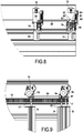
- each rack 18 is mounted on the upper face of a central partition 5a presented by each longitudinal section 5 2 , 5 3 .
- each longitudinal section 5 2 , 5 3 has a core 5b extending horizontally and from which rises the middle partition 5a and on either side, an outer wing 5c and an inner wing 5d.
- the central partition 5a is equipped with the guide track 8 produced below the external face receiving the rack 18.
- each longitudinal section 5 2 , 5 3 is produced by extrusion.
- the profiles can be assembled end to end at will to adapt to the dimensions of the surface 2 to be covered.
- the central partition 5a and the internal wing 5d delimit between them a gutter 5e plumb with which the end edges of the blades extend to possibly collect rainwater.
- the longitudinal sections 5 2 , 5 3 which are open can advantageously be closed by means of a cover 19 protecting the carriages and mounted between the outer wing 5 and the central partition 5a.
- This cover 19 is provided with brushes 19 1 ( Fig. 5 ) suitable for the passage of the pivot axes 4.
- each carriage 10 1 , 10 2 carrying both a displacement motor 12 and an orientation motor 14 has a bore 40 equipped with a system 41 for guiding in rotation for a tubular shaft 42 inside which is engaged freely a pivot axis 4 which projects from a housing 43 arranged in the end of the blade.
- a pinion 17 which cooperates with the rack 18 is angularly linked to this tubular shaft 42 which is rotated by a toothed wheel 44 fixed on the tubular shaft 42 and meshing with the output shaft of the displacement motor 12.
- the rotation of the tubular shaft 42 leads to the translation of the carriage 10 1 , 10 2 causing the translation of the blade whose pivot axis 4 is pushed during the translation of the carriage.
- Each pinion 17 cooperates indirectly with a pivot axis 4 to drive in translation the pivot axis 4 of the blade 3, by the pivot link produced between the tubular shaft 42 and the pivot axis 4.
- the pivot axis 4 is rotated by the orientation motor 14 whose output shaft cooperates with a toothed wheel 47 locked in rotation with the pivot axis 4 whose opposite end is engaged at the interior of the housing 43 and angularly connected to the blade using any suitable means such as for example connecting pins.
- the pivot axis 4 is thus mounted to rotate freely inside the tubular shaft 42 and can be oriented at will in a stable position determined using the orientation motor 14.
- orientation motors 14 mounted on the trailer carriages are connected to the pivot axes 4 as described above, that is to say that the axis of output of each orientation motor 14 cooperates with the pivot axis which is angularly linked to the blade.
- the displacement system II of the blades 3 thus makes it possible to move the blades between a stowed position in which the blades 3 are attached to one another and a position partially or fully deployed opposite the surface 2.
- a stowed position in which the blades 3 are attached to one another and a position partially or fully deployed opposite the surface 2.
- two blades 3 consecutive or neighboring are separated by a determined pitch of deployment allowing the two said blades to cooperate together to close the corresponding surface when these blades are positioned by the orientation mechanism I according to a closing angle.
- each retractable hitch A provides translation between two neighboring carriages by means of a mechanical connection so that a carriage exerts on the other carriage, a tensile force during the deployment of the blades represented by the arrow F or a thrust force during the folding of the blades 3 in the direction F 1 .
- the lower rank blade exerts its tensile force on the next blade only when the lower rank blade has been moved according to the determined pitch of deployment. Between its stowed position and its deployment of the determined pitch, this blade of lower rank does not drive the following blade in translation. Similarly, the lower row blade exerts its pushing force on the next blade as long as the latter does not occupy its stowed position. Indeed, as soon as this blade occupies its stowed position, the blade of lower rank no longer drives the following blade in translation.
- Each retractable hitch A between the first carriages 10 1 or the second carriages 10 2 of a blade of one row and a blade of a lower row thus comprises, as is presently shown on the Fig. 8 to 11 on the one hand, a mechanism 50 for locking the coupling in a towing position when the blade of lower rank has been moved according to a determined pitch of deployment, and on the other hand, a mechanism 51 for unlocking the locking mechanism 50 to place the hitch in a retracted position and acting as soon as a given row blade occupies its stored position.
- the hitch A is locked by the mechanism 50, in a towing position to pull the next blade.
- the coupling A is unlocked by the unlocking mechanism 51 so that the blade of lower rank can come to occupy its stored position, attached to the blade of given rank.
- each retractable hitch A between the carriages of a blade of a given row and a blade of a lower row comprises, as locking mechanism 50 of the hitch in a towing position, a drawbar 55 carried by the carriage of the lower row blade.
- the drawbar 55 is produced by a rod capable of working in flexion fixed on each carriage of lower rank and extending in direction and at least up to the carriage of neighboring row given when these two carriages are separated of the deployment step.
- the drawbar 55 is fixed to a motorized carriage in order to cooperate with a neighboring trailer carriage.
- Each drawbar 55 is arranged to have a traction surface 57 intended to cooperate with a first stop 58 carried by the carriage of the blade of given rank (neighboring trailer carriage) only when the blade of lower rank has been moved according to its determined stroke of deployment and during the deployment operation of said blades ( Fig. 10 ).
- the first stop 58 is produced by one face of a plate 59 fixed on the carriage and oriented in the opposite direction to the carriage of lower rank.
- This plate 59 includes an opening 60 for the drawbar 55 which always remains engaged through this opening 60 between the passage from the retracted position to the towing position and vice versa.
- Each drawbar 55 is arranged to also present a thrust surface 61 intended to cooperate with a second stop 62 carried by the carriage of the blade of given rank (neighboring trailer carriage), as long as during the storage operation of said blades, said blade blade of given rank has not reached its stowed position.
- the second stop 62 is produced by the opposite face of the plate 59 forming the first stop 58.
- the traction 57 and thrust 61 surfaces are produced by folds arranged on the rod 55 so that the latter has portions extending transversely with respect to the direction of general extension of the rod 55.
- Each drawbar 55 cooperates, when the blade of given rank has reached its stowed position, with the mechanism 51 for unlocking the locking mechanism 50 to remove the contact between the thrust surface 61 and the second stop 62 so that the blade of lower rank can move until it reaches its stowed position.
- this unlocking mechanism 51 is carried by each motorized carriage so that the drawbar 55 carried by a motorized carriage is intended to cooperate with this mechanism carried by the neighboring motorized carriage of higher rank which is already stored (and between which a trailer trolley is positioned).
- the unlocking mechanism 51 is also mounted on the storage edge 5 1 of the support structure 5 to cooperate with the locking mechanism 50 of the penultimate blade.
- the unlocking mechanism 51 is produced by a ramp 64 leading to lifting the end 55 1 of the drawbar ( Fig. 8 ) during movement of the motorized carriage in the direction of folding so that the thrust surface 61 can escape the second stop 62, passing through the passage opening 60 so that the carriage of lower rank can continue its translation to the stowed position. So as shown in the Fig. 18 , the carriages can be in the stowed position, attached to each other with the drawbars 55 being in the retracted position by extending one next to the other.
- Each ramp 64 which is carried by a carriage can be fixed with a possibility of adjustment for reversing or advancing the unlocking distance between two neighboring carriages.
- each drawbar 55 has its pushing surface 61 which has passed beyond the plate 59.
- each pushing surface 61 is extended opposite the end free 55 1 of the drawbar 55, by a ramp 66 allowing, during the movement of the carriages in the direction of deployment F, that the thrust surface 61 easily crosses the passage opening 60.
- the cooperation of this ramp 66 with the plate 59 leads to the lifting of the drawbar 55 allowing the thrust surface to pass to the other side of the plate 59.
- the drawbar 55 then occupies a neutral position in which the surface of traction 57 is positioned opposite the first stop 58, thus preventing disassembly between the two carriages. It is clear that each drawbar 55 has a capacity for bending in order to be able to pass from a stop position to a retracted position and vice versa.
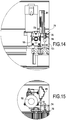
- each retractable hitch A between the first carriages or the second carriages of a blade of a given row and a blade of a lower row comprises a system 70 for holding in position the blade of given row , as long as the lower row blade has not been moved according to its determined deployment path ( Fig. 12 to 15 ).
- This holding system 70 makes it possible to keep a blade in the stowed position and to prevent this blade being able to move, under the action of the retractable hitch, when moving a blade of lower rank.
- each retractable hitch A between the first carriages or the second carriages of a blade of a given row adjacent to a blade of a lower row comprises an unlocking system 71 of the holding system 70 as soon as the blade of lower row has been moved along its course deployment.
- this lower row blade can drive in translation, by the coupling A, the blade of next row.
- each retractable hitch A comprises as a holding system 70 in position of a blade of a lower rank, a spring rod 73 carried by a carriage of said blade of lower rank and cooperating with a retainer 74 placed on a carriage next to a blade of given rank.
- the storage edge 5 1 of the carrying structure 5 is also equipped with a stop 74 to cooperate with the spring rod 73 fitted to the carriage of the first row blade.
- Each spring rod 73 has a conformation or a fold 75 suitable for, on the one hand, locking behind the retainer 74 and, on the other hand, being released from the retainer under the action of the tensile force exerted by the blade. of lower rank.
- the spring rod 73 has an elastic deformation capacity to pass from its blocking position ( Fig. 14-15 ) in its unlocked position ( Fig. 12-13 ), by pivoting in a plane.
- each retractable hitch A between the adjacent carriages of a blade of a given row and a blade of a lower row comprises two articulated links 76, 77 to form using the coupling hitch mechanism 50 , an incompressible compass in the towing position.
- These two links 76, 77 are mounted articulated on the carriages being articulated between them.
- the locking mechanism 50 comprises a spring member 78 acting on one of the links in order to ensure contact with a stop 79 carried by a link to form a rigid compass.
- one of the links comes to bear on the carriage of the blade already stored to form a flexible compass under the action of such an unlocking mechanism 51, making it possible to place the hitch in a retracted position.
- one of the rods 76 acts on a mechanism 70 for locking in position of a blade, formed by a bolt resiliently urged to cooperate with the rack 8.
- the installation 1 also includes sensors, not shown, for the position and displacement of the blades 3. Such sensors make it possible to know the position of each of the blades 3 at any time throughout their journey on the guide track. Such displacement position sensors can be made in any suitable way.
- the position and displacement sensors comprise contact sensors each mounted on a carriage and capable of being actuated by a stop carried by the carriage situated upstream in the direction of output of the blades or by the supporting structure for the carriage of the last blade in the direction of exit.
- These contact sensors make it possible to identify the position of the blades and in particular in their stored position.
- the displacement sensors also include sensors for measuring the rotation of the displacement motors such as encoders. These displacement sensors make it possible to know the linear displacement of the carriages 10 1 , 10 2 along their guide track 8.
- the position and displacement sensors also include sensors for measuring the rotation of the orientation motors 14 making it possible to be able to know the angular orientation of the blades 3.
- the position and displacement sensors also include sensors for detecting the direction of 'orientation of the blades.
- the installation 1 also comprises a control device not shown, connected to the position and displacement sensors, to the displacement motors 12 and to the orientation motors 14 making it possible to move in translation at least part of the blades 3 and orient said translated blades.
- a control device thus makes it possible to control the operation of the displacement motors 12 and of the orientation motors 14 so as to make it possible to cover and discover one or more zones of the surface 2 either on demand or according to prerecorded programs.
- the control device preferably includes a remote control and power supply unit with respect to the installation and connected to electronic circuits 81 on board the carriages 10 1 , 10 2 .
- This control device preferably comprises a remote control enabling the installation according to the invention to be controlled remotely.
- control device includes a calibration mode allowing the installation to position the blades 3 in a defined position in order to identify their position.
- the pilot control system before first use, the motors 12, 14 in order to place the different blades 3 in the stowed position with an upright orientation.
- the position of the blades 3 in the stored position is identified by the contact sensors.
- control device has several pre-recorded modes of use, each corresponding to a type of positioning of the blades.
- provision may be made to preregister a total coverage mode of the surface 2 or a partial coverage mode.
- provision can be made to pre-register the orientation of the blades either in the upright position or in the closed position, or in an intermediate position.
- the blades 3 are successively pulled out of their stowed position after a determined deployment pitch and until the blades occupy their desired exit position.
- the pitch of deployment of the blades corresponds to the spacing between two consecutive contiguous blades in the horizontal or vertical screen position.
- the displacement motors 12 of the first blade 3 1 are controlled to ensure translation in the direction F of the carriages 10 1 and 10 2 of this first blade 3. It should be noted that the holding system 70 of this first blade 3 1 is unlocked upon translation of this first blade whose spring rod 73 pivots to escape from the stop 74 carried by the carriage of the next blade. The translation of this first blade 3 1 leads to the drive of each retractable hitch A fixed to (x) carriage (s) of this first blade without causing the translation of the second blade remaining in the stowed position thanks to the system 70 for holding in position of said blade.
- the ramp 66 of the drawbar cooperates with the plate 59 to allow the thrust surface 61 to pass through the passage opening 60 and to the traction surface 57 to come to be positioned opposite of the first stop 58 at the end of the cooperation of the ramp 66 with the wafer.
- the traction surface 57 of each drawbar 55 comes to cooperate with the first stop 58 carried by the carriage of the second blade allowing the translation of this second blade ( Fig. 11 ).
- the displacement motor 12 of the second blade is controlled to ensure translation in the direction F of the carriages 10 1 and 10 2 of this second blade. It should be noted that the holding system 70 of this second blade is unlocked simultaneously, taking into account the tensile force exerted on this second blade.
- the control device thus successively drives the displacement motors 12 associated with the blades 3 to be deployed.
- the control device stops the operation of the displacement motors 12 when the blades 3 occupy their desired deployed position.
- the operating motors 12 are stopped operating either directly by the user as a function of their choice of deployment of the blades or according to a prerecorded program providing for the positioning of the blades 3 in defined positions ensured by the sensors for measuring the displacement motor rotation 12.
- control device can control the opening motors 14 to orient the blades 3.
- control device controls the operation of the orientation motors 14 only if the blades 3 occupy a fixed position different from the stowed position. It is recalled that the blades are erected in the stowed position.
- the control device controls the orientation motors 14 of the deployed blades to position the latter in upright position.
- the control device simultaneously controls the motors 12 for moving these blades to successively bring them into their stored position detected by the position sensors.
- each retractable hitch A remains in the towing position with the application of a thrust force from each blade of lower rank on the neighboring blade of higher rank the last deployed blade does not reach its stowed position. It should be noted that in the embodiment of the couplings by the drawbars, the thrust surface 61 of each drawbar 55 cooperates with the second stop 62 carried by the carriage of the blade of higher rank ( Fig. 10 ).
- each retractable hitch A fixed between the latter blade and the blade of lower rank retracts.
- each drawbar 55 carried by the penultimate blade cooperates with the ramp 64 carried by the storage edge 5 1 of the support structure 5 making it possible to lift the drawbar to remove the contact between the thrust surface 61 and the second stop 62.
- Each drawbar 55 passes through the passage opening 60 so that the lower row blade can move until it reaches its stowed position.
- the control device can thus selectively drive the displacement 12 and orientation motors 14 of the blades to cover all or part of the surface 2, with blades in the upright, closed or intermediate. It should be noted that the blades 3 are translated only in the upright position.
Landscapes
- Engineering & Computer Science (AREA)
- Architecture (AREA)
- Civil Engineering (AREA)
- Structural Engineering (AREA)
- Physics & Mathematics (AREA)
- Electromagnetism (AREA)
- Automatic Assembly (AREA)
- Blinds (AREA)
- Treatment Of Fiber Materials (AREA)
Claims (20)
- Vorrichtung zum Abdecken und Freilegen einer Oberfläche (2), die von einer Trägerstruktur (5) begrenzt wird, mit einstellbaren Lamellen (3), wobei die Vorrichtung umfasst:- eine Serie von einstellbaren Lamellen (3), die ungeradzahlige Lamellen, von denen mindestens eine als Kopf bezeichnet wird, und geradzahlige Lamellen, die zwischen den ungeradzahligen Lamellen angeordnet sind, umfassen, wobei sich diese einstellbaren Lamellen parallel zueinander entlang ihrer Längsränder erstrecken und an jedem ihrer Endränder mit einer Schwenkachse (4) versehen sind,- wobei jede Lamelle (3) von ihren Schwenkachsen (4) mit einem Satz eines ersten Schlittens (101) und eines zweiten Schlittens (102) getragen wird, die translatorisch entlang Wegen (8) zur Führung geführt werden,- zwei Wege (8) zur translatorischen Führung der Schlitten, die in der Trägerstruktur (5) aufgenommen sind, indem sie parallel zueinander entlang zwei gegenüberliegenden Seiten der Oberfläche angeordnet sind,- ein System (I) zum Einstellen der Lamellen (3), das geeignet ist, um das Schwenken mindestens bestimmter der Lamellen sicherzustellen, damit die Längsränder der Lamellen aneinander angrenzen oder nicht aneinander angrenzen, um die entsprechende Oberfläche jeweils zu schließen oder zu öffnen,- ein System (II) zum Verschieben der Lamellen (3) zwischen einer rangierten Position, in der die Lamellen miteinander gekoppelt sind, und einer ausgefahrenen Position, in der mindestens ein Teil der Lamellen, der mindestens eine Kopflamelle umfasst, in Bezug auf die Oberfläche ausgefahren ist,- Positionssensoren der Lamellen (3),- und eine Steuervorrichtung, die mit den Sensoren, mit dem System (II) zum Verschieben und mit dem System (I) zum Einstellen verbunden ist, um mindestens einen Teil der Lamellen translatorisch zu verschieben und die translatorisch verschobenen Lamellen einzustellen, wobei das System (II) zum Verschieben umfasst, für jede vorhandene geradzahlige Lamelle, einerseits eine einziehbare Kupplung (A), die zwischen dem ersten Schlitten der Lamelle und dem ersten Schlitten, der zu der Kopflamelle oder zu der benachbarten nachrangigen Lamelle gehört, und andererseits ein System (S) zum translatorischen Antreiben des zweiten Schlittens der Lamelle, und für jede vorhandene ungeradzahlige Lamelle, eine einziehbare Kupplung (A), die zwischen dem zweiten Schlitten (102) der Lamelle und dem zweiten Schlitten (102), der zur der benachbarten nachrangigen Lamelle gehört, und ein System (S) zum translatorischen Antreiben des ersten Schlittens der Lamelle, wobei die Vorrichtung dadurch gekennzeichnet ist, dass das System (II) zum Verschieben, für jede Kopflamelle, Motoren (12) zum Verschieben umfasst, die in den ersten und zweiten Schlitten eingerichtet sind, dadurch, dass die Vorrichtung Verschiebungssensoren der Lamellen (3) umfasst, und dadurch, dass die Motoren (12) zum Verschieben, die in den Schlitten eingerichtet sind, mit Mechanismen zur Transformation der Rotationsbewegung in eine Translationsbewegung der Lamellen in einer Richtung parallel zu dem Führungsweg verbunden sind.
- Vorrichtung nach Anspruch 1, dadurch gekennzeichnet, dass das System (S) zum translatorischen Antreiben eines Schlittens entweder einen Motor (12) zum Verschieben, der in dem Schlitten eingerichtet ist, oder eine einziehbare Kupplung (A), die jeweils zwischen den ersten oder zweiten Schlitten der Lamelle und der benachbarten nachrangigen Lamelle befestigt ist, umfasst.
- Vorrichtung nach einem der Ansprüche 1 bis 2, dadurch gekennzeichnet, dass das System (II) zum Verschieben eine einzige Kopflamelle und geradzahlige und ungeradzahlige Lamellen umfasst, die Paare von aufeinanderfolgenden Lamellen mit einer gemeinsamen Lamelle in jeder von ihnen bilden, wobei diese Lamellen durch einziehbare Kupplungen (A) verbunden sind, die abwechselnd zwischen den ersten Schlitten und den zweiten Schlitten der Paare von aufeinanderfolgenden Lamellen montiert sind.
- Vorrichtung nach einem der Ansprüche 1 bis 2, dadurch gekennzeichnet, dass das System (II) zum Verschieben mehrere Kopflamellen umfasst, die jeweils mindestens eine Lamelle antreiben, um eine Gruppe von Lamellen zu bilden, wobei diese Gruppen von Lamellen nicht miteinander verbunden sind.
- Vorrichtung nach einem der Ansprüche 1 bis 4, dadurch gekennzeichnet, dass die einziehbare Kupplung (A) zwischen den ersten Schlitten oder den zweiten Schlitten einer Lamelle mit einem gegebenen Rang und einer nachrangigen Lamelle umfasst einerseits ein System (70) zum Halten der Lamelle mit dem gegebenen Rang in Position, solange die nachrangige Lamelle gemäß ihrem bestimmten Ausfahrverlauf nicht verschoben wurde, und andererseits ein System (71) zum Entriegeln des Haltesystems (70), sobald die nachrangige Lamelle gemäß ihrem Ausfahrverlauf verschoben wurde.
- Vorrichtung nach einem der Ansprüche 1 bis 5, dadurch gekennzeichnet, dass jede einziehbare Kupplung (A) zwischen den ersten Schlitten oder den zweiten Schlitten einer Lamelle mit einem Rang und einer nachrangigen Lamelle umfasst einerseits einen Mechanismus (50) zum Verriegeln der Kupplung in einer Schleppposition, wenn die nachrangige Lamelle gemäß einem bestimmten Ausfahrschritt verschoben wurde, und andererseits einen Mechanismus (51) zum Entriegeln des Verriegelungsmechanismus (50), um die Kupplung in eine eingezogene Position zu platzieren, und der wirkt, sobald die Lamelle mit dem gegebenen Rang ihre rangierte Position einnimmt.
- Vorrichtung nach Anspruch 6, dadurch gekennzeichnet, dass jede einziehbare Kupplung (A) zwischen den Schlitten einer Lamelle mit einem gegebenen Rang und einer nachrangigen Lamelle, als Mechanismus (50) zum Verriegeln der Kupplung in einer Schleppposition, eine Deichsel (55) umfasst, die von dem Schlitten der nachrangigen Lamelle getragen wird und eingerichtet ist, um aufzuweisen einerseits eine Zugfläche (57), die dazu bestimmt ist, mit einem ersten Anschlag (58) zusammenzuwirken, der von dem Schlitten der Lamelle mit dem gegebenen Rang getragen wird, nur wenn die nachrangige Lamelle gemäß ihrem bestimmten Ausfahrverlauf verschoben wurde, und während der Ausfahroperation der Lamellen, und andererseits eine Schubfläche (61), die dazu bestimmt ist, mit einem zweiten Anschlag (62) zusammenzuwirken, der von dem Schlitten der Lamelle mit dem gegebenen Rang getragen wird, solange während der Rangieroperation der Lamellen die Lamelle mit dem gegebenen Rang ihre rangierte Position nicht erreicht hat, wobei die Deichsel (55), wenn die Lamelle mit dem gegebenen Rang ihre rangierte Position erreicht hat, mit dem Entriegelungsmechanismus (51) zwischen der Schubfläche (61) und dem zweiten Anschlag (62) zusammenwirkt, damit sich die nachrangige Lamelle verschieben kann, bis sie ihre rangierte Position erreicht.
- Vorrichtung nach Anspruch 6, dadurch gekennzeichnet, dass jede einziehbare Kupplung (A), als System (70) zum Halten einer Lamelle in Position, einen Federstab (73) umfasst, der von der Lamelle getragen wird und mit einem Stopper (74) zusammenwirkt, der stromaufwärts von der Lamelle platziert ist, wobei der Federstab eine Form (75) aufweist, die geeignet ist, um aus dem Stopper unter der Einwirkung der Zugkraft freigegeben zu werden, die von der nachrangigen Lamelle ausgeübt wird.
- Vorrichtung nach einem der Ansprüche 1 bis 6, dadurch gekennzeichnet, dass jede einziehbare Kupplung (A) zwischen den Schlitten einer Lamelle mit einem gegebenen Rang und einer nachrangigen Lamelle zwei Gelenkstangen (76, 77) umfasst, um, mit dem Mechanismus (50) zum Verriegeln der Kupplung, eine nicht zusammendrückbare Ausstellvorrichtung in der eingefahrenen Position zu bilden, wobei die beiden Stangen (76, 77) eine nachgiebige Ausstellvorrichtung unter der Einwirkung des Entriegelungsmechanismus des Verriegelungsmechanismus bilden, um die Kupplung in einer eingezogene Position zu platzieren.
- Vorrichtung nach einem der Ansprüche 1 bis 9, dadurch gekennzeichnet, dass die Motoren (12) zum Verschieben jeweils in Rotation ein Zahnrad (17) antreiben, welches mit einer Zahnstange (18) zusammenwirkt, die auf der Trägerstruktur in einer Richtung parallel zu dem Führungsweg montiert ist.
- Vorrichtung nach einem der Ansprüche 1 bis 10, dadurch gekennzeichnet, dass das Einstellsystem (I), für jedes Paar von Schlitten, die eine Lamelle ausstatten, mindestens einen Einstellmotor (14) umfasst, der in mindestens einem der Schlitten eingerichtet ist und winkelmäßig mit der Schwenkachse (4) verbunden ist.
- Vorrichtung nach Anspruch 11, dadurch gekennzeichnet, dass, für jede Lamelle, der Motor (12) zum Verschieben und der Motor (14) zum Einstellen auf demselben Schlitten montiert sind, wobei diese Schlitten, die mit diesen Motoren ausgestattet sind, abwechselnd von einer Lamelle zur anderen auf jeder Seite der abzudeckenden oder freizulegenden Oberfläche angeordnet sind.
- Vorrichtung nach einem der Ansprüche 11 bis 12, dadurch gekennzeichnet, dass jeder Schlitten (102), der mit einem Motor (12) zum Verschieben und einem Motor (14) zum Einstellen ausgestattet ist, einen Hauptkörper (15) zum Stützen für den Motor zum Verschieben und den Motor zum Einstellen umfasst, wobei der Hauptkörper (15) mit einem System (41) zum Führen einer rohrförmigen Welle (42) in Rotation versehen ist, die mit einem Zahnrad (17) ausgestattet ist und von dem Motor zum Verschieben in Rotation angetrieben wird, wobei die Schwenkachse (4) im Inneren der rohrförmigen Welle (42) montiert ist, wobei sie von dem Motor (14) zum Einstellen in Rotation angetrieben wird und fest in Rotation mit der Lamelle montiert ist.
- Vorrichtung nach einem der Ansprüche 1 bis 13, dadurch gekennzeichnet, dass die Positions- und Verschiebungssensoren der Lamellen Kontaktsensoren umfassen, die auf den Schlitten eines Führungswegs montiert sind, um von dem Schlitten betätigt zu werden, der stromaufwärts in der Richtung des Ausgangs der Lamellen angeordnet ist, oder von der Trägerstruktur für den Schlitten der letzten Lamelle in der Richtung des Ausgangs.
- Vorrichtung nach einem der Ansprüche 1 bis 14, dadurch gekennzeichnet, dass die Positions- und Verschiebungssensoren der Lamellen (3) Sensoren zum Messen der Rotation der Motoren zum Verschieben und der Rotation der Motoren zum Einstellen sowie Sensoren zum Detektieren der Einstellrichtung der Lamellen umfassen.
- Vorrichtung nach einem der Ansprüche 1 bis 15, dadurch gekennzeichnet, dass die Steuervorrichtung einen Kalibriermodus und mehrere voreingestellte Verwendungsmodi umfasst, die jeweils einem Positionierungstyp der Lamellen entsprechen.
- Vorrichtung nach einem der Ansprüche 1 bis 16, dadurch gekennzeichnet, dass die Steuervorrichtung den Betrieb der Motoren zum Verschieben (12) und zum Einstellen (14) derart steuert, dass vor dem Befehl zum Verschieben einer Lamelle die Steuervorrichtung den Motor zum Einstellen der Lamelle steuert, um sie in die vertikale Position zu platzieren, wenn sie diese vertikale Position nicht einnimmt.
- Vorrichtung nach einem der Ansprüche 1 bis 17, dadurch gekennzeichnet, dass, für einen Modus zum konsistenten Verwenden am Ausgang einer bestimmten Anzahl von Lamellen aus ihrer rangierten Position, die Steuervorrichtung den Betrieb der Motoren (12) zum Verschieben der auszufahrenden Lamellen derart steuert, dass jedes Mal, wenn die erste Lamelle um einen Schritt vorgeschoben wird, die Lamelle, die sich stromaufwärts befindet, in eine Verschiebung gesteuert wird, wobei die Motoren (12) zum Verschieben der Lamellen gesteuert werden, bis die Lamellen ihre Ausgangsposition einnehmen.
- Vorrichtung nach Anspruch 18, dadurch gekennzeichnet, dass die Steuervorrichtung die Motoren (12) zum Verschieben derart steuert, dass der Schritt der Verschiebung der Lamellen dem Abstand zwischen zwei aufeinanderfolgenden Lamellen entspricht, die in einer Schirmposition aneinander angrenzen.
- Vorrichtung nach einem der Ansprüche 11 bis 19, dadurch gekennzeichnet, dass die Steuervorrichtung den Betrieb der Motoren (14) zum Einstellen nur steuert, wenn die Lamelle eine feste Position einnimmt, die von der rangierten Position verschieden ist.
Applications Claiming Priority (2)
| Application Number | Priority Date | Filing Date | Title |
|---|---|---|---|
| FR1653199A FR3049976B1 (fr) | 2016-04-12 | 2016-04-12 | Installation pour couvrir et decouvrir une surface a l'aide de lames orientables automotrices attelees |
| PCT/FR2017/050877 WO2017178757A1 (fr) | 2016-04-12 | 2017-04-12 | Installation pour couvrir et découvrir une surface a l'aide de lames orientables automotrices attelées |
Publications (2)
| Publication Number | Publication Date |
|---|---|
| EP3443177A1 EP3443177A1 (de) | 2019-02-20 |
| EP3443177B1 true EP3443177B1 (de) | 2020-01-08 |
Family
ID=57233521
Family Applications (1)
| Application Number | Title | Priority Date | Filing Date |
|---|---|---|---|
| EP17722097.7A Active EP3443177B1 (de) | 2016-04-12 | 2017-04-12 | Vorrichtung zum abdecken und freilegen einer oberfläche mit gekoppelten selbstfahrenden einstellbaren lamellen |
Country Status (5)
| Country | Link |
|---|---|
| US (1) | US11015349B2 (de) |
| EP (1) | EP3443177B1 (de) |
| ES (1) | ES2787380T3 (de) |
| FR (1) | FR3049976B1 (de) |
| WO (1) | WO2017178757A1 (de) |
Families Citing this family (20)
| Publication number | Priority date | Publication date | Assignee | Title |
|---|---|---|---|---|
| BE1022563B1 (nl) * | 2014-10-16 | 2016-06-02 | Renson Sunprotection Screens Nv | Lamelleninrichting |
| FR3049976B1 (fr) * | 2016-04-12 | 2022-08-05 | Biossun | Installation pour couvrir et decouvrir une surface a l'aide de lames orientables automotrices attelees |
| CN108166688B (zh) | 2017-05-08 | 2019-11-05 | 宁波万汇休闲用品有限公司 | 遮蔽篷装置 |
| AU2018360615A1 (en) * | 2017-10-30 | 2020-06-11 | Advanced Design Innovations Pty Ltd | Retractable roof/wall assembly |
| EP3495582A1 (de) | 2017-12-08 | 2019-06-12 | Activa Awning Inc. | Markisenvorrichtung |
| FR3075838B1 (fr) * | 2017-12-27 | 2020-02-28 | Biossun | Installation a lames orientables independamment les unes des autres |
| US10914068B2 (en) * | 2018-02-06 | 2021-02-09 | Infinity Canopy, Inc. | Adjustable awning and retractable canopy system |
| IT201800005621A1 (it) * | 2018-05-23 | 2019-11-23 | Unità di rivestimento verticale perfezionata | |
| DE102018005087A1 (de) * | 2018-06-27 | 2020-01-02 | Stobag Ag | Lamellendach |
| DE102018118392A1 (de) | 2018-07-30 | 2020-01-30 | Warema Renkhoff Se | Vorrichtung zur Begrenzung des Stellweges von Antrieben |
| FR3093339B1 (fr) * | 2019-02-28 | 2021-03-05 | Biossun | Installation pour couvrir une surface à l’aide de lames orientables translatées à plat |
| IT201900024514A1 (it) * | 2019-12-18 | 2021-06-18 | Brianzatende S R L | Struttura di copertura |
| CN211597897U (zh) * | 2019-12-20 | 2020-09-29 | 南京航空航天大学 | 一种抗强台风的自适应钢结构冷却塔 |
| US11168481B2 (en) * | 2019-12-30 | 2021-11-09 | Yardistry Us, Llc | Louver system and method of assembling same |
| ES2964600T3 (es) | 2020-01-23 | 2024-04-08 | Marin Rodriguez Francisco Javier | Estructura plegable para ser utilizada como parasol, persiana o valla |
| BE1028221B1 (nl) * | 2020-04-21 | 2021-11-22 | Renson Sunprotection Screens | Een set profielen voor het opbouwen van een overkapping |
| BE1028728B1 (nl) * | 2020-10-22 | 2022-05-23 | Renson Sunprotection Screens | Dakinrichting voor een overkapping, set onderdelen voor het opbouwen van de dakinrichting, en overkapping omvattende de dakinrichting |
| US11725390B2 (en) * | 2021-04-30 | 2023-08-15 | Jackson Design & Remodeling, Inc. | Louvered patio cover control system |
| IT202200004634A1 (it) * | 2022-03-10 | 2023-09-10 | Tender Srl | Dispositivo di azionamento per una pergola |
| ES2952145A1 (es) * | 2022-03-21 | 2023-10-27 | Codeval Aluminium Sl | Pérgola de lamas giratorias |
Family Cites Families (51)
| Publication number | Priority date | Publication date | Assignee | Title |
|---|---|---|---|---|
| US2179882A (en) * | 1938-09-20 | 1939-11-14 | Durre Allen | Blind |
| US2556352A (en) * | 1946-10-09 | 1951-06-12 | Adolph H Wellensiek | Adjustable louver assembly |
| US2642018A (en) * | 1950-02-23 | 1953-06-16 | Weeber Karl William | Greenhouse ridge assembly |
| US3284951A (en) * | 1963-10-30 | 1966-11-15 | Clarence M Shapiro | Louvered structure |
| FR1475733A (fr) * | 1966-01-12 | 1967-04-07 | Planet Usines | Perfectionnements aux volets pour fenêtres et ouvertures |
| US3763606A (en) * | 1971-09-17 | 1973-10-09 | A Rindebong | Weather protecting and view obstructing screen |
| US3744544A (en) * | 1971-09-23 | 1973-07-10 | A Wellensiek | Outside venetian blind construction |
| CH613094A5 (de) * | 1976-06-22 | 1979-09-14 | Plascon Ag | |
| US4449563A (en) * | 1982-05-26 | 1984-05-22 | Rca Corporation | Counterbalance system for sagging rotating element |
| US4527355A (en) * | 1983-02-24 | 1985-07-09 | Zeon Kasei Co., Ltd. | Opening and closing type louver device |
| US4571897A (en) * | 1983-07-21 | 1986-02-25 | Fred Kerr | Apparatus for mounting sheet material and mounting assembly and structural surface formed therewith |
| US5289863A (en) * | 1989-12-13 | 1994-03-01 | Schon B.V. | Apparatus for suspending lamellar sun-blinds or the like |
| US5732507A (en) * | 1993-11-04 | 1998-03-31 | H.V. Aluminium Pty. Limited | Louvre assembly |
| AU694383B2 (en) * | 1995-11-20 | 1998-07-16 | Louver Shield Pty Limited | Interclosing panel screen |
| US5873202A (en) * | 1997-07-07 | 1999-02-23 | Parks; Charles Sherman | Slidably adjustable rigid awning |
| US6202363B1 (en) * | 1998-06-08 | 2001-03-20 | Chao-Jen Chang | Shielding canopy |
| JP2995301B1 (ja) * | 1999-02-10 | 1999-12-27 | 有限会社美鈴 | ブラインドのル―バ―反転装置 |
| US6405782B1 (en) * | 2000-11-16 | 2002-06-18 | Keng Mu Cheng | Transmission system for a motor-driven blind |
| US20030056326A1 (en) * | 2001-09-25 | 2003-03-27 | Kuentin Ko | Connecting member of a slide of a window covering assembly allowing interchange of window coverings |
| US7681620B2 (en) * | 2003-01-30 | 2010-03-23 | Parma Shutter Technologies Ltd | Stacking mechanism |
| IL154223A0 (en) * | 2003-01-30 | 2003-07-31 | Parma Shutter Technologies Ltd | Door shutter mechanism |
| US6866078B1 (en) * | 2003-12-03 | 2005-03-15 | Ya-Yin Lin | Sliding carriage for vertical blind |
| JP4025318B2 (ja) * | 2004-07-06 | 2007-12-19 | アメリカンテント株式会社 | 開閉式屋根 |
| US7520091B2 (en) * | 2004-07-09 | 2009-04-21 | Friedman Daniel B | Adaptable roof system |
| US8201609B1 (en) * | 2004-10-13 | 2012-06-19 | Mark Kitterman | Panelless shutter |
| US7552755B2 (en) * | 2006-11-28 | 2009-06-30 | Ya-Ying Lin | Movable seat of a vertical curtain |
| US20090071612A1 (en) * | 2007-09-19 | 2009-03-19 | Hans Hung | Carrier assembly for vertical blind |
| ES2369337T3 (es) * | 2008-02-15 | 2011-11-29 | Hunter Douglas Industries B.V. | Mecanismo de giro de lamas orientables. |
| GB201007328D0 (en) * | 2010-05-04 | 2010-06-16 | Gray Matter Alpha Ltd | Lourve vane system |
| GB201102111D0 (en) * | 2011-02-08 | 2011-03-23 | Wjp Holdings Ltd | Thermal shutter system |
| AU2012202652B2 (en) * | 2011-05-09 | 2016-05-05 | Hunter Douglas, Inc | Shutter with field serviceable louvers |
| US8756873B1 (en) * | 2011-12-05 | 2014-06-24 | Mark Hire | Transforming awning |
| US8528621B2 (en) * | 2012-02-01 | 2013-09-10 | Murphy-Farrell Development L.L.L.P. | Solar window shade |
| WO2013119835A1 (en) * | 2012-02-07 | 2013-08-15 | Jesse Villarreal | Louver assembly |
| US20150159430A1 (en) * | 2012-02-27 | 2015-06-11 | Dazhi Huang | Motorized Curtain and Blind Tracking Systems |
| US8656980B2 (en) * | 2012-03-22 | 2014-02-25 | Alcoa Inc. | Adjustable light shelf |
| ITMI20121911A1 (it) * | 2012-11-09 | 2014-05-10 | Frigerio Tende Da Sole S R L | Struttura di copertura a pale basculanti. |
| US20140175240A1 (en) * | 2012-11-15 | 2014-06-26 | C. Scott Selzer | Bracket for louvered roof systems |
| GB2511053B (en) * | 2013-02-20 | 2017-09-20 | Orangebox Ltd | A ceiling panel |
| AU2013382035B2 (en) * | 2013-03-14 | 2018-03-08 | Hunter Douglas Inc. | Shutter panel for an architectural opening |
| SI2850260T1 (sl) * | 2013-06-07 | 2016-01-29 | Renson Sunprotection-Screens Nv | Letvena struktura |
| US9222264B1 (en) * | 2013-10-02 | 2015-12-29 | Luke S. Reid | Retractable awning |
| FR3012486B1 (fr) * | 2013-10-31 | 2015-11-13 | Soliso Europ | Panneau a lames pour construction legere telle que pergola, abris de jardin ou similaire et construction legere integrant un tel panneau |
| ITBA20140016U1 (it) * | 2014-07-04 | 2016-01-04 | Smarlite S R L | "meccanismo di impacchettamento e rotazione di lamelle orientabili atte a proteggere dai raggi solari, pioggia o altri agenti atmosferici" |
| EP2980346A1 (de) * | 2014-07-31 | 2016-02-03 | Hunter Douglas Industries B.V. | Blendenanordnung |
| FR3027334B1 (fr) * | 2014-10-15 | 2017-02-24 | Biossun | Installation pour couvrir et decouvrir une surface a l'aide de lames orientables automotrices |
| BE1022563B1 (nl) * | 2014-10-16 | 2016-06-02 | Renson Sunprotection Screens Nv | Lamelleninrichting |
| US9644374B2 (en) * | 2014-12-20 | 2017-05-09 | Michael Ivic | Pergola cover |
| FR3035423B1 (fr) * | 2015-04-24 | 2021-06-18 | Castel Jean Louis | Dispositif d'occultation multifonctions a modules, notamment pour pergola |
| FR3049976B1 (fr) * | 2016-04-12 | 2022-08-05 | Biossun | Installation pour couvrir et decouvrir une surface a l'aide de lames orientables automotrices attelees |
| US10094122B1 (en) * | 2017-06-06 | 2018-10-09 | Optimal Tasarim Uygulama Ve Yapi Sistemleri San. Ve Tic. Anomim Sirketi | Automatic wide angle panel roof |
-
2016
- 2016-04-12 FR FR1653199A patent/FR3049976B1/fr active Active
-
2017
- 2017-04-12 EP EP17722097.7A patent/EP3443177B1/de active Active
- 2017-04-12 ES ES17722097T patent/ES2787380T3/es active Active
- 2017-04-12 US US16/092,236 patent/US11015349B2/en active Active
- 2017-04-12 WO PCT/FR2017/050877 patent/WO2017178757A1/fr active Application Filing
Non-Patent Citations (1)
| Title |
|---|
| None * |
Also Published As
| Publication number | Publication date |
|---|---|
| FR3049976B1 (fr) | 2022-08-05 |
| EP3443177A1 (de) | 2019-02-20 |
| US20190145107A1 (en) | 2019-05-16 |
| ES2787380T3 (es) | 2020-10-16 |
| WO2017178757A1 (fr) | 2017-10-19 |
| US11015349B2 (en) | 2021-05-25 |
| FR3049976A1 (fr) | 2017-10-13 |
Similar Documents
| Publication | Publication Date | Title |
|---|---|---|
| EP3443177B1 (de) | Vorrichtung zum abdecken und freilegen einer oberfläche mit gekoppelten selbstfahrenden einstellbaren lamellen | |
| EP3207190B1 (de) | Einheit zum abdecken und aufdecken einer oberfläche mit selbstangetriebenen verstellbaren lamellen | |
| EP0021933B1 (de) | Vorrichtung zur Abstandsveränderung der Sitze in Linienflugzeugen | |
| EP2231978B1 (de) | Verschlussvorrichtung mit mindestens einem ziehharmonikaartig gefalteten verschluss | |
| WO2020174195A1 (fr) | Installation pour couvrir une surface a l'aide de lames orientables translatees a plat | |
| EP3438371B1 (de) | Anpassbare pergola | |
| FR2891561A1 (fr) | Toiture ouvrante, notamment pour constructions legeres du type veranda | |
| FR3018064A1 (fr) | Procede d'ouverture / fermeture d'une porte de cabine d'aeronef et systeme d'assemblage de porte de cabine dans un fuselage d'aeronef. | |
| WO2005026473A1 (fr) | Dispositif et procede pour recouvrir et decouvrir une surface par un element de couverture enroulable | |
| WO2015063433A1 (fr) | Installation pour couvrir et découvrir une surface a l'aide de lames orientables sans espace de rangement dédie | |
| WO2014072638A1 (fr) | Installation télescospique de rangement a l'intérieur d'une fosse d'un élément de couverture | |
| EP2635759B1 (de) | Jalousierbarer rollladen | |
| EP3180486B1 (de) | Taschenartige öffnungsplatte mit horizontal gelenkigen schwenkbaren klappen | |
| EP4321702A1 (de) | Sonnen- oder wetterschutzanlage | |
| FR2942841A1 (fr) | Dispositif d'occultation notamment pour vehicule automobile | |
| FR2962759A1 (fr) | Volet roulant inclinable automatique | |
| EP3394367A1 (de) | Teleskopische einheit zur lagerung eines abdeckelements in einem lagerraum | |
| FR3044974A1 (fr) | Dispositif d'occultation d'une surface vitree d'un pavillon de vehicule automobile a rails non paralleles. | |
| EP1337733B1 (de) | Vorrichtung zur betätigung eines garagentors oder dergleichen | |
| FR2509363A1 (fr) | Dispositif d'occultation a lames paralleles coulissantes et orientables a commande electro-mecanique pour baies vitrees verticales, horizontales ou inclinees de grandes dimensions | |
| FR2934311A1 (fr) | Dispositif d'entrainement d'un organe mobile en deplacement | |
| FR3038930A1 (fr) | Element d'ouverture et/ou de fermeture d'un passage | |
| EP3748118A1 (de) | Betätigungsvorrichtung eines verdunkelungssystems einer öffnung, und verdunkelungsanlage, bei der eine solche vorrichtung eingesetzt wird | |
| FR2906548A1 (fr) | Store d'exterieur a projection a l'italienne | |
| FR2829172A1 (fr) | Dispositif de fermeture du type repliable en accordeon |
Legal Events
| Date | Code | Title | Description |
|---|---|---|---|
| STAA | Information on the status of an ep patent application or granted ep patent |
Free format text: STATUS: UNKNOWN |
|
| STAA | Information on the status of an ep patent application or granted ep patent |
Free format text: STATUS: THE INTERNATIONAL PUBLICATION HAS BEEN MADE |
|
| PUAI | Public reference made under article 153(3) epc to a published international application that has entered the european phase |
Free format text: ORIGINAL CODE: 0009012 |
|
| STAA | Information on the status of an ep patent application or granted ep patent |
Free format text: STATUS: REQUEST FOR EXAMINATION WAS MADE |
|
| 17P | Request for examination filed |
Effective date: 20181012 |
|
| AK | Designated contracting states |
Kind code of ref document: A1 Designated state(s): AL AT BE BG CH CY CZ DE DK EE ES FI FR GB GR HR HU IE IS IT LI LT LU LV MC MK MT NL NO PL PT RO RS SE SI SK SM TR |
|
| AX | Request for extension of the european patent |
Extension state: BA ME |
|
| DAV | Request for validation of the european patent (deleted) | ||
| DAX | Request for extension of the european patent (deleted) | ||
| GRAP | Despatch of communication of intention to grant a patent |
Free format text: ORIGINAL CODE: EPIDOSNIGR1 |
|
| STAA | Information on the status of an ep patent application or granted ep patent |
Free format text: STATUS: GRANT OF PATENT IS INTENDED |
|
| INTG | Intention to grant announced |
Effective date: 20190802 |
|
| GRAS | Grant fee paid |
Free format text: ORIGINAL CODE: EPIDOSNIGR3 |
|
| GRAA | (expected) grant |
Free format text: ORIGINAL CODE: 0009210 |
|
| STAA | Information on the status of an ep patent application or granted ep patent |
Free format text: STATUS: THE PATENT HAS BEEN GRANTED |
|
| AK | Designated contracting states |
Kind code of ref document: B1 Designated state(s): AL AT BE BG CH CY CZ DE DK EE ES FI FR GB GR HR HU IE IS IT LI LT LU LV MC MK MT NL NO PL PT RO RS SE SI SK SM TR |
|
| REG | Reference to a national code |
Ref country code: GB Ref legal event code: FG4D Free format text: NOT ENGLISH |
|
| REG | Reference to a national code |
Ref country code: CH Ref legal event code: EP |
|
| REG | Reference to a national code |
Ref country code: DE Ref legal event code: R096 Ref document number: 602017010739 Country of ref document: DE |
|
| REG | Reference to a national code |
Ref country code: IE Ref legal event code: FG4D Free format text: LANGUAGE OF EP DOCUMENT: FRENCH |
|
| REG | Reference to a national code |
Ref country code: AT Ref legal event code: REF Ref document number: 1222892 Country of ref document: AT Kind code of ref document: T Effective date: 20200215 |
|
| REG | Reference to a national code |
Ref country code: NL Ref legal event code: MP Effective date: 20200108 |
|
| REG | Reference to a national code |
Ref country code: CH Ref legal event code: NV Representative=s name: BOVARD AG PATENT- UND MARKENANWAELTE, CH |
|
| REG | Reference to a national code |
Ref country code: LT Ref legal event code: MG4D |
|
| PG25 | Lapsed in a contracting state [announced via postgrant information from national office to epo] |
Ref country code: NO Free format text: LAPSE BECAUSE OF FAILURE TO SUBMIT A TRANSLATION OF THE DESCRIPTION OR TO PAY THE FEE WITHIN THE PRESCRIBED TIME-LIMIT Effective date: 20200408 Ref country code: PT Free format text: LAPSE BECAUSE OF FAILURE TO SUBMIT A TRANSLATION OF THE DESCRIPTION OR TO PAY THE FEE WITHIN THE PRESCRIBED TIME-LIMIT Effective date: 20200531 Ref country code: FI Free format text: LAPSE BECAUSE OF FAILURE TO SUBMIT A TRANSLATION OF THE DESCRIPTION OR TO PAY THE FEE WITHIN THE PRESCRIBED TIME-LIMIT Effective date: 20200108 Ref country code: RS Free format text: LAPSE BECAUSE OF FAILURE TO SUBMIT A TRANSLATION OF THE DESCRIPTION OR TO PAY THE FEE WITHIN THE PRESCRIBED TIME-LIMIT Effective date: 20200108 Ref country code: NL Free format text: LAPSE BECAUSE OF FAILURE TO SUBMIT A TRANSLATION OF THE DESCRIPTION OR TO PAY THE FEE WITHIN THE PRESCRIBED TIME-LIMIT Effective date: 20200108 Ref country code: LT Free format text: LAPSE BECAUSE OF FAILURE TO SUBMIT A TRANSLATION OF THE DESCRIPTION OR TO PAY THE FEE WITHIN THE PRESCRIBED TIME-LIMIT Effective date: 20200108 |
|
| PG25 | Lapsed in a contracting state [announced via postgrant information from national office to epo] |
Ref country code: IS Free format text: LAPSE BECAUSE OF FAILURE TO SUBMIT A TRANSLATION OF THE DESCRIPTION OR TO PAY THE FEE WITHIN THE PRESCRIBED TIME-LIMIT Effective date: 20200508 Ref country code: BG Free format text: LAPSE BECAUSE OF FAILURE TO SUBMIT A TRANSLATION OF THE DESCRIPTION OR TO PAY THE FEE WITHIN THE PRESCRIBED TIME-LIMIT Effective date: 20200408 Ref country code: GR Free format text: LAPSE BECAUSE OF FAILURE TO SUBMIT A TRANSLATION OF THE DESCRIPTION OR TO PAY THE FEE WITHIN THE PRESCRIBED TIME-LIMIT Effective date: 20200409 Ref country code: LV Free format text: LAPSE BECAUSE OF FAILURE TO SUBMIT A TRANSLATION OF THE DESCRIPTION OR TO PAY THE FEE WITHIN THE PRESCRIBED TIME-LIMIT Effective date: 20200108 Ref country code: SE Free format text: LAPSE BECAUSE OF FAILURE TO SUBMIT A TRANSLATION OF THE DESCRIPTION OR TO PAY THE FEE WITHIN THE PRESCRIBED TIME-LIMIT Effective date: 20200108 Ref country code: HR Free format text: LAPSE BECAUSE OF FAILURE TO SUBMIT A TRANSLATION OF THE DESCRIPTION OR TO PAY THE FEE WITHIN THE PRESCRIBED TIME-LIMIT Effective date: 20200108 |
|
| REG | Reference to a national code |
Ref country code: DE Ref legal event code: R097 Ref document number: 602017010739 Country of ref document: DE |
|
| REG | Reference to a national code |
Ref country code: ES Ref legal event code: FG2A Ref document number: 2787380 Country of ref document: ES Kind code of ref document: T3 Effective date: 20201016 |
|
| PG25 | Lapsed in a contracting state [announced via postgrant information from national office to epo] |
Ref country code: DK Free format text: LAPSE BECAUSE OF FAILURE TO SUBMIT A TRANSLATION OF THE DESCRIPTION OR TO PAY THE FEE WITHIN THE PRESCRIBED TIME-LIMIT Effective date: 20200108 Ref country code: SK Free format text: LAPSE BECAUSE OF FAILURE TO SUBMIT A TRANSLATION OF THE DESCRIPTION OR TO PAY THE FEE WITHIN THE PRESCRIBED TIME-LIMIT Effective date: 20200108 Ref country code: RO Free format text: LAPSE BECAUSE OF FAILURE TO SUBMIT A TRANSLATION OF THE DESCRIPTION OR TO PAY THE FEE WITHIN THE PRESCRIBED TIME-LIMIT Effective date: 20200108 Ref country code: CZ Free format text: LAPSE BECAUSE OF FAILURE TO SUBMIT A TRANSLATION OF THE DESCRIPTION OR TO PAY THE FEE WITHIN THE PRESCRIBED TIME-LIMIT Effective date: 20200108 Ref country code: EE Free format text: LAPSE BECAUSE OF FAILURE TO SUBMIT A TRANSLATION OF THE DESCRIPTION OR TO PAY THE FEE WITHIN THE PRESCRIBED TIME-LIMIT Effective date: 20200108 Ref country code: SM Free format text: LAPSE BECAUSE OF FAILURE TO SUBMIT A TRANSLATION OF THE DESCRIPTION OR TO PAY THE FEE WITHIN THE PRESCRIBED TIME-LIMIT Effective date: 20200108 |
|
| REG | Reference to a national code |
Ref country code: DE Ref legal event code: R119 Ref document number: 602017010739 Country of ref document: DE |
|
| PLBE | No opposition filed within time limit |
Free format text: ORIGINAL CODE: 0009261 |
|
| STAA | Information on the status of an ep patent application or granted ep patent |
Free format text: STATUS: NO OPPOSITION FILED WITHIN TIME LIMIT |
|
| REG | Reference to a national code |
Ref country code: AT Ref legal event code: MK05 Ref document number: 1222892 Country of ref document: AT Kind code of ref document: T Effective date: 20200108 |
|
| PG25 | Lapsed in a contracting state [announced via postgrant information from national office to epo] |
Ref country code: MC Free format text: LAPSE BECAUSE OF FAILURE TO SUBMIT A TRANSLATION OF THE DESCRIPTION OR TO PAY THE FEE WITHIN THE PRESCRIBED TIME-LIMIT Effective date: 20200108 |
|
| 26N | No opposition filed |
Effective date: 20201009 |
|
| PG25 | Lapsed in a contracting state [announced via postgrant information from national office to epo] |
Ref country code: DE Free format text: LAPSE BECAUSE OF NON-PAYMENT OF DUE FEES Effective date: 20201103 Ref country code: AT Free format text: LAPSE BECAUSE OF FAILURE TO SUBMIT A TRANSLATION OF THE DESCRIPTION OR TO PAY THE FEE WITHIN THE PRESCRIBED TIME-LIMIT Effective date: 20200108 Ref country code: LU Free format text: LAPSE BECAUSE OF NON-PAYMENT OF DUE FEES Effective date: 20200412 |
|
| PG25 | Lapsed in a contracting state [announced via postgrant information from national office to epo] |
Ref country code: PL Free format text: LAPSE BECAUSE OF FAILURE TO SUBMIT A TRANSLATION OF THE DESCRIPTION OR TO PAY THE FEE WITHIN THE PRESCRIBED TIME-LIMIT Effective date: 20200108 Ref country code: SI Free format text: LAPSE BECAUSE OF FAILURE TO SUBMIT A TRANSLATION OF THE DESCRIPTION OR TO PAY THE FEE WITHIN THE PRESCRIBED TIME-LIMIT Effective date: 20200108 |
|
| PG25 | Lapsed in a contracting state [announced via postgrant information from national office to epo] |
Ref country code: IE Free format text: LAPSE BECAUSE OF NON-PAYMENT OF DUE FEES Effective date: 20200412 |
|
| GBPC | Gb: european patent ceased through non-payment of renewal fee |
Effective date: 20210412 |
|
| PG25 | Lapsed in a contracting state [announced via postgrant information from national office to epo] |
Ref country code: GB Free format text: LAPSE BECAUSE OF NON-PAYMENT OF DUE FEES Effective date: 20210412 |
|
| PG25 | Lapsed in a contracting state [announced via postgrant information from national office to epo] |
Ref country code: TR Free format text: LAPSE BECAUSE OF FAILURE TO SUBMIT A TRANSLATION OF THE DESCRIPTION OR TO PAY THE FEE WITHIN THE PRESCRIBED TIME-LIMIT Effective date: 20200108 Ref country code: MT Free format text: LAPSE BECAUSE OF FAILURE TO SUBMIT A TRANSLATION OF THE DESCRIPTION OR TO PAY THE FEE WITHIN THE PRESCRIBED TIME-LIMIT Effective date: 20200108 Ref country code: CY Free format text: LAPSE BECAUSE OF FAILURE TO SUBMIT A TRANSLATION OF THE DESCRIPTION OR TO PAY THE FEE WITHIN THE PRESCRIBED TIME-LIMIT Effective date: 20200108 |
|
| PG25 | Lapsed in a contracting state [announced via postgrant information from national office to epo] |
Ref country code: MK Free format text: LAPSE BECAUSE OF FAILURE TO SUBMIT A TRANSLATION OF THE DESCRIPTION OR TO PAY THE FEE WITHIN THE PRESCRIBED TIME-LIMIT Effective date: 20200108 Ref country code: AL Free format text: LAPSE BECAUSE OF FAILURE TO SUBMIT A TRANSLATION OF THE DESCRIPTION OR TO PAY THE FEE WITHIN THE PRESCRIBED TIME-LIMIT Effective date: 20200108 |
|
| PGFP | Annual fee paid to national office [announced via postgrant information from national office to epo] |
Ref country code: FR Payment date: 20230331 Year of fee payment: 7 |
|
| PG25 | Lapsed in a contracting state [announced via postgrant information from national office to epo] |
Ref country code: IT Free format text: LAPSE BECAUSE OF NON-PAYMENT OF DUE FEES Effective date: 20220412 |
|
| P01 | Opt-out of the competence of the unified patent court (upc) registered |
Effective date: 20230504 |
|
| PGFP | Annual fee paid to national office [announced via postgrant information from national office to epo] |
Ref country code: IT Payment date: 20230407 Year of fee payment: 7 Ref country code: ES Payment date: 20230511 Year of fee payment: 7 Ref country code: CH Payment date: 20230531 Year of fee payment: 7 |
|
| PGFP | Annual fee paid to national office [announced via postgrant information from national office to epo] |
Ref country code: BE Payment date: 20230427 Year of fee payment: 7 |