EP3438342B1 - Vorrichtung zur herstellung von zerfasertem material und blattherstellungsvorrichtung - Google Patents
Vorrichtung zur herstellung von zerfasertem material und blattherstellungsvorrichtung Download PDFInfo
- Publication number
- EP3438342B1 EP3438342B1 EP18186120.4A EP18186120A EP3438342B1 EP 3438342 B1 EP3438342 B1 EP 3438342B1 EP 18186120 A EP18186120 A EP 18186120A EP 3438342 B1 EP3438342 B1 EP 3438342B1
- Authority
- EP
- European Patent Office
- Prior art keywords
- magnet
- feedstock
- defibrated material
- shreds
- foreign matter
- Prior art date
- Legal status (The legal status is an assumption and is not a legal conclusion. Google has not performed a legal analysis and makes no representation as to the accuracy of the status listed.)
- Active
Links
Images




Classifications
-
- D—TEXTILES; PAPER
- D21—PAPER-MAKING; PRODUCTION OF CELLULOSE
- D21B—FIBROUS RAW MATERIALS OR THEIR MECHANICAL TREATMENT
- D21B1/00—Fibrous raw materials or their mechanical treatment
- D21B1/04—Fibrous raw materials or their mechanical treatment by dividing raw materials into small particles, e.g. fibres
- D21B1/06—Fibrous raw materials or their mechanical treatment by dividing raw materials into small particles, e.g. fibres by dry methods
-
- B—PERFORMING OPERATIONS; TRANSPORTING
- B27—WORKING OR PRESERVING WOOD OR SIMILAR MATERIAL; NAILING OR STAPLING MACHINES IN GENERAL
- B27N—MANUFACTURE BY DRY PROCESSES OF ARTICLES, WITH OR WITHOUT ORGANIC BINDING AGENTS, MADE FROM PARTICLES OR FIBRES CONSISTING OF WOOD OR OTHER LIGNOCELLULOSIC OR LIKE ORGANIC MATERIAL
- B27N3/00—Manufacture of substantially flat articles, e.g. boards, from particles or fibres
- B27N3/007—Manufacture of substantially flat articles, e.g. boards, from particles or fibres and at least partly composed of recycled material
-
- D—TEXTILES; PAPER
- D21—PAPER-MAKING; PRODUCTION OF CELLULOSE
- D21B—FIBROUS RAW MATERIALS OR THEIR MECHANICAL TREATMENT
- D21B1/00—Fibrous raw materials or their mechanical treatment
- D21B1/02—Pretreatment of the raw materials by chemical or physical means
-
- B—PERFORMING OPERATIONS; TRANSPORTING
- B27—WORKING OR PRESERVING WOOD OR SIMILAR MATERIAL; NAILING OR STAPLING MACHINES IN GENERAL
- B27N—MANUFACTURE BY DRY PROCESSES OF ARTICLES, WITH OR WITHOUT ORGANIC BINDING AGENTS, MADE FROM PARTICLES OR FIBRES CONSISTING OF WOOD OR OTHER LIGNOCELLULOSIC OR LIKE ORGANIC MATERIAL
- B27N3/00—Manufacture of substantially flat articles, e.g. boards, from particles or fibres
- B27N3/002—Manufacture of substantially flat articles, e.g. boards, from particles or fibres characterised by the type of binder
-
- B—PERFORMING OPERATIONS; TRANSPORTING
- B27—WORKING OR PRESERVING WOOD OR SIMILAR MATERIAL; NAILING OR STAPLING MACHINES IN GENERAL
- B27N—MANUFACTURE BY DRY PROCESSES OF ARTICLES, WITH OR WITHOUT ORGANIC BINDING AGENTS, MADE FROM PARTICLES OR FIBRES CONSISTING OF WOOD OR OTHER LIGNOCELLULOSIC OR LIKE ORGANIC MATERIAL
- B27N3/00—Manufacture of substantially flat articles, e.g. boards, from particles or fibres
- B27N3/04—Manufacture of substantially flat articles, e.g. boards, from particles or fibres from fibres
-
- B—PERFORMING OPERATIONS; TRANSPORTING
- B27—WORKING OR PRESERVING WOOD OR SIMILAR MATERIAL; NAILING OR STAPLING MACHINES IN GENERAL
- B27N—MANUFACTURE BY DRY PROCESSES OF ARTICLES, WITH OR WITHOUT ORGANIC BINDING AGENTS, MADE FROM PARTICLES OR FIBRES CONSISTING OF WOOD OR OTHER LIGNOCELLULOSIC OR LIKE ORGANIC MATERIAL
- B27N3/00—Manufacture of substantially flat articles, e.g. boards, from particles or fibres
- B27N3/08—Moulding or pressing
- B27N3/10—Moulding of mats
- B27N3/12—Moulding of mats from fibres
-
- D—TEXTILES; PAPER
- D21—PAPER-MAKING; PRODUCTION OF CELLULOSE
- D21B—FIBROUS RAW MATERIALS OR THEIR MECHANICAL TREATMENT
- D21B1/00—Fibrous raw materials or their mechanical treatment
- D21B1/04—Fibrous raw materials or their mechanical treatment by dividing raw materials into small particles, e.g. fibres
- D21B1/06—Fibrous raw materials or their mechanical treatment by dividing raw materials into small particles, e.g. fibres by dry methods
- D21B1/08—Fibrous raw materials or their mechanical treatment by dividing raw materials into small particles, e.g. fibres by dry methods the raw material being waste paper; the raw material being rags
-
- D—TEXTILES; PAPER
- D21—PAPER-MAKING; PRODUCTION OF CELLULOSE
- D21B—FIBROUS RAW MATERIALS OR THEIR MECHANICAL TREATMENT
- D21B1/00—Fibrous raw materials or their mechanical treatment
- D21B1/04—Fibrous raw materials or their mechanical treatment by dividing raw materials into small particles, e.g. fibres
- D21B1/06—Fibrous raw materials or their mechanical treatment by dividing raw materials into small particles, e.g. fibres by dry methods
- D21B1/08—Fibrous raw materials or their mechanical treatment by dividing raw materials into small particles, e.g. fibres by dry methods the raw material being waste paper; the raw material being rags
- D21B1/10—Fibrous raw materials or their mechanical treatment by dividing raw materials into small particles, e.g. fibres by dry methods the raw material being waste paper; the raw material being rags by cutting actions
-
- D—TEXTILES; PAPER
- D21—PAPER-MAKING; PRODUCTION OF CELLULOSE
- D21F—PAPER-MAKING MACHINES; METHODS OF PRODUCING PAPER THEREON
- D21F9/00—Complete machines for making continuous webs of paper
-
- D—TEXTILES; PAPER
- D21—PAPER-MAKING; PRODUCTION OF CELLULOSE
- D21F—PAPER-MAKING MACHINES; METHODS OF PRODUCING PAPER THEREON
- D21F9/00—Complete machines for making continuous webs of paper
- D21F9/02—Complete machines for making continuous webs of paper of the Fourdrinier type
-
- D—TEXTILES; PAPER
- D21—PAPER-MAKING; PRODUCTION OF CELLULOSE
- D21H—PULP COMPOSITIONS; PREPARATION THEREOF NOT COVERED BY SUBCLASSES D21C OR D21D; IMPREGNATING OR COATING OF PAPER; TREATMENT OF FINISHED PAPER NOT COVERED BY CLASS B31 OR SUBCLASS D21G; PAPER NOT OTHERWISE PROVIDED FOR
- D21H23/00—Processes or apparatus for adding material to the pulp or to the paper
- D21H23/02—Processes or apparatus for adding material to the pulp or to the paper characterised by the manner in which substances are added
- D21H23/04—Addition to the pulp; After-treatment of added substances in the pulp
- D21H23/20—Apparatus therefor
-
- Y—GENERAL TAGGING OF NEW TECHNOLOGICAL DEVELOPMENTS; GENERAL TAGGING OF CROSS-SECTIONAL TECHNOLOGIES SPANNING OVER SEVERAL SECTIONS OF THE IPC; TECHNICAL SUBJECTS COVERED BY FORMER USPC CROSS-REFERENCE ART COLLECTIONS [XRACs] AND DIGESTS
- Y02—TECHNOLOGIES OR APPLICATIONS FOR MITIGATION OR ADAPTATION AGAINST CLIMATE CHANGE
- Y02W—CLIMATE CHANGE MITIGATION TECHNOLOGIES RELATED TO WASTEWATER TREATMENT OR WASTE MANAGEMENT
- Y02W30/00—Technologies for solid waste management
- Y02W30/50—Reuse, recycling or recovery technologies
- Y02W30/64—Paper recycling
Definitions
- a sheet manufacturing apparatus 1000 according to this embodiment of the invention is described first with reference to FIG. 1 .
- the +Z-axis direction is referred to below as the positive direction, and the -Z-axis direction as the negative direction.
- the direction pointed to by the arrows indicating the axial direction is referred to as the + direction (positive, or forward, direction), and the side at the origin (base) of the indicated direction is the - direction (negative direction).
- the XY plane is the horizontal plane
- the +Z-axis direction is the direction of gravity.
- the XYZ axes in FIG. 1 are the same as the XYZ axes in the other figures.
- wetting devices 204, 206, 208, 210, 212 may be designed as desired, and steam, evaporative, warm air vaporization, ultrasonic, or other type of humidification method may be used.
- the screener 40 has a drum 41, and a housing 43 enclosing the drum 41.
- the defibrated material introduced from the inlet 42 is conveyed with the air current into the drum 41, and the first screened material drops through the mesh of the drum 41 as the drum 41 turns.
- the second screened material that cannot pass through the mesh of the drum 41 flows with the air current introduced from the inlet 42 to the drum 41 to the outlet 44, is conveyed through another conduit 8 and returned through the conduit 8 to the defibrator 160 of the defibrated material manufacturing device 100, and is defibrated again.
- Moist air is supplied by wetting device 204 to the space enclosing the drum 41. This moist air wets the first screened material inside the screener 40. As a result, accretion of first screened material on the mesh belt 46 by static electricity is reduced, and the first screened material can be easily separated from the mesh belt 46. Accretion of first screened material by static electricity on the rotor 49 and the inside walls of the housing 43 can also be suppressed. In addition, impurities can be efficiently suctioned by the suction device 48.
- a rotor 49 that breaks up the first web W1 accumulated on the mesh belt 46 is disposed on the downstream side of the mesh belt 46 in the conveyance direction of the first web W1.
- the first web W1 is separated from the mesh belt 46 and broken up by the rotor 49 at the position where the mesh belt 46 is returned to the upstream side by a roller 47.
- the fragments 33 cut by the rotor 49 drop through a conduit 7, and are carried to the mixing device 50 by the current flowing through the conduit 7.
- additive When the feeder of the outlet 52a is not operating, additive is not supplied from the outlet 52a to the conduit 54, but if there is negative pressure in the conduit 54, additive may flow through the conduit 54 even if the feeder of the outlet 52a is stopped. However, this flow of additive can be reliably stopped by closing the path that connects the feeder to the conduit 54 with the shutter.
- the additive that the additive supply device 52 supplies includes resin for binding fibers.
- the resin contained in the additive is a thermoplastic resin or thermoset resin, such as AS resin, ABS resin, polypropylene, polyethylene, polyvinyl chloride, polystyrene, acrylic resin, polyester resin, polyethylene terephthalate, polyethylene ether, polyphenylene ether, polybutylene terephthalate, nylon, polyimide, polycarbonate, polyacetal, polyphenylene sulfide, and polyether ether ketone. These resins may be used individually or in a desirable combination.
- the additive may contain only a single material or a mixture, both of which may comprise multiple types of particulate each comprising a single or multiple materials.
- the additive supplied may also be in fibrous or powder form.
- Humidified air is supplied by the wetting device 208 to the space surrounding the drum 61.
- the inside of the air-laying device 60 can be humidified by the humidified air, fiber and particles accumulating on the housing 63 due to static electricity can be suppressed, fiber and particles can be made to precipitate quickly on the mesh belt 72, and a second web W2 of a desired form can be made.
- a soft, fluffy second web W2 containing much air is thus formed by passing through the air-laying device 60 and web forming device 70.
- the second web W2 accumulated on the mesh belt 72 is then conveyed to the sheet forming device 80.
- Air carrying mist is supplied by the wetting device 212 to the conveyance path of the mesh belt 72 on the downstream side of the air-laying device 60.
- mist generated by the wetting device 212 is supplied to the second web W2, and the water content of the second web W2 is adjusted. Accretion of fiber on the mesh belt 72 due to static electricity is also suppressed.
- side 132A the side 132 of the magnet 131 on the -Z-axis direction side indicated by the bold solid line
- side 132B the side 132 of the magnet 131 on the +Z-axis direction side indicated by the bold dotted line
- the defibrated material manufacturing device 100 includes an input hopper 110 into which feedstock (coarse product D) is loaded; one or more dividers 115; a vibratory linear feeder 120 that conveys the feedstock (coarse product D) by vibration in the +X-axis direction; a metering hopper 140 that measures feedstock (shreds P1 detangled from the coarse product D) conveyed from the vibratory linear feeder 120, and discharges the metered feedstock (shreds P1); and the defibrator 160 that defibrates the feedstock (shreds P1) supplied from the storage hopper 140 into defibrated material.
- a removal device 130 is disposed between the vibratory linear feeder 120 and metering hopper 140. Described further below, the removal device 130 removes foreign matter (metallic foreign matter M) contained in the feedstock (shreds P) as non-fiber foreign matter (foreign matter not suited to making sheets S).
- the vibratory linear feeder 120 is an example of a conveyance device
- the metering hopper 140 is an example of a storage device and a measuring device.
- the coarse product D is clumps of shreds P containing fiber in multiple layers broken by a shredder or other type of grinder into pieces approximately 5 cm to 10 cm square. More specifically, the coarse product D is agglomerations of multiple shreds P.
- the coarse product D formed by cutting feedstock with a shredder or other type of grinder are conveyed by a worker and loaded into the input hopper 110.
- the coarse product D loaded into the input hopper 110 is then discharged from the outlet 111 of the input hopper 110 onto the base 126 of the upstream vibratory linear feeder 121.
- this embodiment of the invention has two input hoppers 110, upstream vibratory linear feeders 121, downstream vibratory linear feeders 122, and metering hoppers 140.
- the input hopper 110 comprises a first input hopper 110A and a second input hopper 110B;
- the upstream vibratory linear feeder 121 comprises a first upstream vibratory linear feeder 121A and a second upstream vibratory linear feeder 121B;
- the downstream vibratory linear feeder 122 comprises a first downstream vibratory linear feeder 122A and a second downstream vibratory linear feeder 122B;
- the metering hopper 140 comprises a first metering hopper 140A and a second metering hopper 140B.
- the first input hopper 110A, dividers 115, first upstream vibratory linear feeder 121A, first downstream vibratory linear feeder 122A, removal device 130, and first metering hopper 140A form a first feedstock supply unit 101 that supplies defibrated material feedstock (coarse product D) to the defibrator 160; and the second input hopper 110B, dividers 115, second upstream vibratory linear feeder 121B, second downstream vibratory linear feeder 122B, removal device 130, and second metering hopper 140B form a second feedstock supply unit 102 that supplies defibrated material feedstock (coarse product D) to the defibrator 160.
- the metering hopper 140 can consistently weigh a specific amount of coarse product D at a constant speed as a result of coarse product D being consistently supplied at a constant rate from the downstream vibratory linear feeder 122 to the metering hopper 140.
- the conveyance speed of the downstream vibratory linear feeder 122 is set slow so that coarse product D is consistently supplied at a constant rate from the downstream vibratory linear feeder 122 to the metering hopper 140.
- This embodiment of the invention has two feedstock supply units that supply feedstock for defibrated material to the defibrator 160, and compared with a configuration having only one feedstock supply unit, the processing capacity of the feedstock supply units together is greater than or equal to the processing capacity of the defibrator 160.
- the number of feedstock supply units is set so that the processing capacity of the feedstock supply units is (about) equal to (e.g. ⁇ 10% of) the processing capacity of the defibrator 160.
- the coarse product D When the coarse product D is conveyed in the +X-axis direction by vibration by the upstream vibratory linear feeder 121 and downstream vibratory linear feeder 122, the coarse product D, which is clumps of many shreds P, is defibrated into individual shreds P.
- the coarse product D loaded onto the base 126 of the vibratory linear feeder 120 (vibratory linear feeders 121, 122) is conveyed in the +X-axis direction by vibration, and is defibrated by the vibrations into individual shreds P.
- the shreds P defibrated from the coarse product D are then discharged as defibrated material feedstock from the downstream vibratory linear feeder 122.
- the shreds P discharged from the downstream vibratory linear feeder 122 drop in the +Z-axis direction (direction of gravity), and are supplied to the metering hopper 140.
- a removal device 130 is disposed between the downstream vibratory linear feeder 122 and the metering hopper 140.
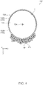
- the removal device 130 includes a magnet 131, a coating 133 covering the magnet 131, and a rotating shaft 134 rotationally supporting the magnet 131.
- the shreds P discharged from the downstream vibratory linear feeder 122 drop toward area C on the side 132A of the magnet 131 as indicated by the star in the figure. More specifically, the shreds P (feedstock) dropping in the +Z-axis direction (direction of gravity) contact the magnet 131 in area C. More specifically, shreds P (feedstock) dropping in the +Z-axis direction (direction of gravity) meet the magnet 131 at area C.
- the area C where the shreds P (feedstock) dropping in the +Z-axis direction make contact extends on the Y-axis on side 132A of the magnet 131.
- the angle of intersection between the plane formed by area C and the rotating shaft 134, and the XY plane (horizontal plane), is approximately 45 degrees.
- the coarse product D is conveyed through the vibratory linear feeder 120, the coarse product D is separated into individual shreds P by the vibration.
- the coarse product D containing metallic foreign matter M may not be attracted to the magnet 131, and may pass the magnet 131 and be supplied to the metering hopper 140.
- the coarse product D containing metallic foreign matter M is broken into shreds P of a weight that can be captured by the magnet 131, metallic foreign matter M and shreds P2 containing metallic foreign matter M are held by the magnet 131 and not supplied to the metering hopper 140.
- the metallic foreign matter M and shreds P2 drop toward area C of the magnet 131, the metallic foreign matter M and shreds P2 are pulled to the area C of the magnet 131.
- the area around area C includes area C, the area on the +Z-axis direction side of area C, and the area on the -Z-axis direction side of area C.
- the load cell 142 is a sensor that detects a force (weight, torque), and has a strain body that deforms proportionally to the force, and a strain gauge that measures the displacement (strain) of the strain body.
- the load cell 142 is disposed to the storage device 141, and weighs the weight of the shreds P1 held in the storage device 141.
- the weight or the supply rate of the defibrated material received from the defibrator 160 varies, the density or thickness of the sheet S manufactured by the recycled paper manufacturing system 200 will also vary.
- the weight and supply speed of the defibrated material (feedstock for a sheet S) supplied from the defibrated material manufacturing device 100 to the recycled paper manufacturing system 200 are preferably constant.
- metallic foreign matter M such as staples or paper clips is contained in the feedstock for defibration (defibrated material)
- the metallic foreign matter M will also be ground by the defibrator 160 and mixed as minute metallic foreign matter M (such as metallic foreign matter M of approximately 1 mm) with the defibrated material, and minute particles of metallic foreign matter M will be contained in the sheets S produced using the contaminated defibrated material as the feedstock.
- the feedstock (defibrated material) produced by this embodiment of the invention to manufacture sheets S does not contain metallic foreign matter M, the sheets S manufactured from the produced defibrated material therefore do not contain metallic foreign matter M, and this embodiment of the invention therefore prevents such problems.
- the sheet manufacturing apparatus 1000A comprises a sheet manufacturing apparatus 100A that breaks clumps (coarse product D) of shreds P containing fiber into defibrated material, and a recycled paper manufacturing system 200 that manufactures new paper (a sheet S) from the defibrated material.
- the removal device 130A is configured so that magnet 131A contacts shreds P discharged from the downstream vibratory linear feeder 122, and magnet 131B is disposed to a position separated from the shreds P discharged from the downstream vibratory linear feeder 122.
- the magnet 131A is disposed so that it contacts the shreds P (feedstock)
- magnet 131B is disposed so that is separated from the shreds P (feedstock).
- the cleaning process of removing metallic foreign matter M and shreds P2 containing metallic foreign matter M from the magnet 131A can be performed after the position of the magnet 131A and the position of the magnet 131B are interchanged without stopping the defibrated material manufacturing device 100, there is no need to stop the defibrated material manufacturing device 100 for the cleaning operation, and the productivity (operation rate) of the defibrated material manufacturing device 100 can be further improved.
- the removal device 130B of the defibrated material manufacturing device 100B according to this example has a scraper 135 in addition to a magnet 131, coating 133, and rotating shaft 134.
- the removal device 130B according to this example also has a scraper 135 that removes from the magnet 131 metallic foreign matter M and shreds P2 containing metallic foreign matter M attracted by magnetic force to the magnet 131.
- the removal device 130 of the defibrated material manufacturing device 100 in the embodiment described above has a magnet 131, coating 133, and rotating shaft 134, but does not have a scraper 135. This is the main difference between this example and the embodiment described above.
- the area C onto which the shreds P falling in the +Z-axis direction fall changes from being covered with metallic foreign matter M and shreds P2 containing metallic foreign matter M to being not covered with metallic foreign matter M and shreds P2 containing metallic foreign matter M, and the magnet 131 from which metallic foreign matter M and shreds P2 containing metallic foreign matter M were removed by the scraper 135 can continue to reliably remove metallic foreign matter M and shreds P2 containing metallic foreign matter M from the shreds P discharged from the downstream vibratory linear feeder 122.
- the magnet 131 of the removal device 130 is an electromagnet
- the magnetic force of the magnet 131 can be electrically controlled.
- the magnetic strength of the magnet 131 can be reduced by controlling energizing the magnet 131, and metallic foreign matter M and shreds P2 containing metallic foreign matter M can be easily removed from the magnet 131.
- the magnet 131 that removes metallic foreign matter M is disposed between the vibratory linear feeder 120 and the metering hopper 140 of the defibrated material manufacturing device 100, but the invention is not so limited.
- the magnet 131 that removes metallic foreign matter M may be disposed between the vibratory linear feeder 120 and metering hopper 140, between the input hopper 110 and vibratory linear feeder 120, between the upstream vibratory linear feeder 121 and downstream vibratory linear feeder 122, between the metering hopper 140 and defibrator 160, or between the defibrator 160 and recycled paper manufacturing system 200.
- a magnet 131 that removes metallic foreign matter M may be disposed between the screener 40 and mixing device 50, between the mixing device 50 and air-laying device 60, or between the air-laying device 60 and sheet forming device 80.
- the embodiment and variations described above have two feedstock supply units that supply feedstock for defibrated material to the defibrator 160, but the number of feedstock supply units may be less than two or more than two. More specifically, the number of feedstock supply units may be adjusted so that the processing capacity of the feedstock supply units equals the processing capacity of the defibrator 160.
- a sheet as used herein refers to paper (print media) suitable for forming images by ink discharged from nozzles of a printing device, for example.
- a sheet as referred to herein is a medium formed from fiber molded in a specific form, and is not limited to paper used for printing by a printing device.
- the sheet may be a fluid absorbent medium or sound absorbent medium of fiber shaped in a specific form.
- a sheet according to the invention may also be a nonwoven cloth or fiber board of fiber shaped in a specific form.
- a sheet manufacturing apparatus is not limited to a manufacturing apparatus (sheet manufacturing apparatus 1000) that manufactures paper suitable to use in a printing device, and may be a manufacturing apparatus that manufactures moldings of fiber shaped in a specific form, including fluid absorbent media, sound absorbent media, nonwoven cloth, and fiber board.
- the defibrated material manufacturing device 100 can be desirably adapted to a manufacturing apparatus that manufactures moldings of fiber shaped in a specific form, including fluid absorbent media, sound absorbent media, nonwoven cloth, and fiber board.
Landscapes
- Engineering & Computer Science (AREA)
- Life Sciences & Earth Sciences (AREA)
- Wood Science & Technology (AREA)
- Mechanical Engineering (AREA)
- Manufacturing & Machinery (AREA)
- Forests & Forestry (AREA)
- Dry Formation Of Fiberboard And The Like (AREA)
- Paper (AREA)
- Nonwoven Fabrics (AREA)
Claims (11)
- Vorrichtung (100) zur Herstellung eines zerfaserten Materials, die konfiguriert ist, einen Rohstoff (D) von Klumpen (P) von Schnipsel, die Faser enthalten, zu zerfasertem Material zu zerfasern, umfassend:eine Entfernungsvorrichtung (130), die konfiguriert ist, mindestens einen Teil von Fremdsubstanz (M) zu entfernen, die im Rohstoff beinhaltet ist;eine Dosiervorrichtung (142), die konfiguriert ist, das Gewicht des Rohmaterials zu messen, das die Entfernungsvorrichtung passiert hat; undeine Lagervorrichtung (141), die konfiguriert ist, den Rohstoff zu lagern, der durch die Dosiervorrichtung gemessen wurde; und einen Zerfaserer (160), der konfiguriert ist, eine gemessene Menge Rohstoff, die von der Lagervorrichtung zugeleitet wird, zu dem zerfaserten Material zu zerfasern.
- Vorrichtung zur Herstellung eines zerfaserten Materials nach Anspruch 1, ferner umfassend:eine Beförderungsvorrichtung (120), die konfiguriert ist, den Rohstoff durch Vibration zu befördern;wobei die Entfernungsvorrichtung (130) an einer stromabwärts liegenden Seite der Beförderungsvorrichtung in der Beförderungsrichtung angeordnet ist.
- Vorrichtung zur Herstellung eines zerfaserten Materials nach Anspruch 1 oder Anspruch 2, wobei:
die Dosiervorrichtung und die Lagerungsvorrichtung abgestimmt konfiguriert sind. - Vorrichtung zur Herstellung eines zerfaserten Materials nach einem der vorstehenden Ansprüche, wobei:
die Entfernungsvorrichtung einen Magneten (131) zum Anziehen zumindest Teil der Fremdsubstanz (M) aufweist. - Vorrichtung zur Herstellung eines zerfaserten Materials nach Anspruch 4, wobei:die Entfernungsvorrichtung eine drehende Welle (134) aufweist, die konfiguriert ist, den Magneten drehend zu stützen;der Magnet ein Element ist, das in der Achsenrichtung der drehenden Welle lang ist und angeordnet ist, mit dem Rohstoff in Kontakt zu gelangen, der in einer Schwerkraftrichtung fällt; undeine Seite (132A) des Magneten an der gegenüberliegenden Seite wie die Richtung der Schwerkraft (Z) mit dem Rohstoff in Kontakt gelangt, der in der Schwerkraftrichtung fällt.
- Vorrichtung zur Herstellung eines zerfaserten Materials nach Anspruch 4 oder Anspruch 5, wobei:
der Magnet mit Harz (133) beschichtet ist. - Vorrichtung zur Herstellung eines zerfaserten Materials nach einem der Ansprüche 4 bis 6, wobei:
Entfernungsvorrichtung einen Schaber (135) aufweist, der konfiguriert ist, zumindest einen Teil der Fremdsubstanz, die sich auf dem Magneten angesammelt hat, vom Magneten zu entfernen. - Vorrichtung zur Herstellung eines zerfaserten Materials nach einem der Ansprüche 4 bis 7, ferner umfassend:einen ersten Magneten (131A), der in Kontakt mit dem Rohstoff angeordnet ist, wenn der Rohstoff fließt, und einen zweiten Magneten (131B), der abseits des Rohstoffs angeordnet ist;wobei die Entfernungsvorrichtung konfiguriert ist, den ersten Magneten an einer Position abseits des Rohstoffs zu positionieren und den zweiten Magneten in Kontakt mit dem Rohstoff zu positionieren.
- Vorrichtung zur Herstellung eines zerfaserten Materials nach einem der vorstehenden Ansprüche, wobei:
der Rohstoff Altpapier enthält. - Blattherstellungsvorrichtung (1000), umfassend die Vorrichtung zur Herstellung eines zerfaserten Materials nach einem der vorstehenden Ansprüche.
- Blattherstellungsvorrichtung nach Anspruch 10, ferner umfassend:eine Mischvorrichtung (50), die konfiguriert ist, das zerfaserte Material, das von der Vorrichtung zur Herstellung eines zerfaserten Materials zugeleitet wird, mit Harz zu mischen;eine Bahnbildungsvorrichtung (70), die konfiguriert ist, eine Bahn aus einer Mischung des zerfaserten Materials und des Harzes zu bilden; undeine Blattbildungsvorrichtung (80), die konfiguriert ist, ein Blatt durch einen Prozess zu bilden, der mindestens eines von Verdichten und Erwärmen der Bahn enthält.
Applications Claiming Priority (1)
| Application Number | Priority Date | Filing Date | Title |
|---|---|---|---|
| JP2017148134A JP6969195B2 (ja) | 2017-07-31 | 2017-07-31 | 解繊物製造装置、及びシート製造装置 |
Publications (3)
| Publication Number | Publication Date |
|---|---|
| EP3438342A2 EP3438342A2 (de) | 2019-02-06 |
| EP3438342A3 EP3438342A3 (de) | 2019-02-13 |
| EP3438342B1 true EP3438342B1 (de) | 2020-02-19 |
Family
ID=63079850
Family Applications (1)
| Application Number | Title | Priority Date | Filing Date |
|---|---|---|---|
| EP18186120.4A Active EP3438342B1 (de) | 2017-07-31 | 2018-07-27 | Vorrichtung zur herstellung von zerfasertem material und blattherstellungsvorrichtung |
Country Status (5)
| Country | Link |
|---|---|
| US (1) | US11724414B2 (de) |
| EP (1) | EP3438342B1 (de) |
| JP (1) | JP6969195B2 (de) |
| CN (1) | CN109322196B (de) |
| TW (1) | TWI728257B (de) |
Families Citing this family (7)
| Publication number | Priority date | Publication date | Assignee | Title |
|---|---|---|---|---|
| TW201700831A (zh) * | 2015-04-06 | 2017-01-01 | Seiko Epson Corp | 片材製造裝置及片材製造方法 |
| JP2020157544A (ja) * | 2019-03-26 | 2020-10-01 | セイコーエプソン株式会社 | 材料供給装置および繊維体生成装置 |
| JP7447410B2 (ja) * | 2019-08-30 | 2024-03-12 | セイコーエプソン株式会社 | 小片供給装置および繊維体成形装置 |
| JP2022026249A (ja) | 2020-07-30 | 2022-02-10 | セイコーエプソン株式会社 | 原料供給装置 |
| JP7852451B2 (ja) * | 2022-09-28 | 2026-04-28 | セイコーエプソン株式会社 | 繊維体処理装置 |
| CN116377748A (zh) * | 2023-03-14 | 2023-07-04 | 保定市跃进纸箱有限公司 | 一种瓦楞纸回收粉碎制浆装置及工艺 |
| CN117552251B (zh) * | 2024-01-11 | 2024-04-02 | 上海柯林包装集团有限公司 | 一种纸浆模塑包装材料制造装置及制造方法 |
Family Cites Families (17)
| Publication number | Priority date | Publication date | Assignee | Title |
|---|---|---|---|---|
| NL158565B (nl) * | 1974-03-15 | 1978-11-15 | Tno | Werkwijze en inrichting voor het procesmatig terugwinnen van papiervezels uit papierhoudend huishoudelijk of industrieel afval. |
| US5120767A (en) * | 1990-05-21 | 1992-06-09 | Caoutech Inc. | Process and apparatus for reclaiming the economic components of scrap rubber tires |
| JP2006104633A (ja) * | 2004-10-08 | 2006-04-20 | Sanpo Shoko:Kk | 故紙再生処理システム及びその方法 |
| US20110111456A1 (en) * | 2009-04-03 | 2011-05-12 | Xyleco, Inc. | Processing biomass |
| JP5632995B2 (ja) | 2009-08-03 | 2014-12-03 | デュプロ精工株式会社 | ヘッドボックス、抄紙装置及び製紙装置 |
| JP5639406B2 (ja) * | 2010-08-02 | 2014-12-10 | 株式会社シード | 古紙再生装置のパルプ供給装置 |
| WO2012058710A1 (en) * | 2010-11-03 | 2012-05-10 | Fibrecycle Pty Ltd | Paper feeder and method of feeding paper |
| JP5720255B2 (ja) | 2011-01-12 | 2015-05-20 | セイコーエプソン株式会社 | 紙再生装置及び紙再生方法 |
| EP2664708B1 (de) | 2011-01-12 | 2017-04-12 | Seiko Epson Corporation | Recyclingsystem und recyclingverfahren für papier |
| CN102154868A (zh) * | 2011-01-18 | 2011-08-17 | 维达纸业(江门)有限公司 | 一种生活用纸制造工艺中的自动变频碎浆系统 |
| CN102154914B (zh) * | 2011-02-24 | 2013-03-20 | 钟洲 | 制备芳纶纸的方法及由该方法获得的芳纶纸 |
| DE102011120630A1 (de) * | 2011-12-09 | 2013-06-13 | Aerocycle Gmbh | Verfahren zur Altpapieraufbereitung |
| US8986503B2 (en) * | 2013-03-13 | 2015-03-24 | Kadant Inc. | Whitewater recovery process |
| JP6213283B2 (ja) * | 2013-03-27 | 2017-10-18 | セイコーエプソン株式会社 | シート製造装置 |
| JP2014208925A (ja) * | 2013-03-27 | 2014-11-06 | セイコーエプソン株式会社 | シート製造装置 |
| US10675661B2 (en) * | 2015-06-15 | 2020-06-09 | Biofuels Technology Llc | Systems and methods for use in processing of forest residue |
| US20170175338A1 (en) * | 2015-12-18 | 2017-06-22 | The Procter & Gamble Company | Flushable Fibrous Structures |
-
2017
- 2017-07-31 JP JP2017148134A patent/JP6969195B2/ja active Active
-
2018
- 2018-07-26 CN CN201810833524.7A patent/CN109322196B/zh active Active
- 2018-07-27 EP EP18186120.4A patent/EP3438342B1/de active Active
- 2018-07-27 TW TW107126072A patent/TWI728257B/zh active
- 2018-07-30 US US16/048,605 patent/US11724414B2/en active Active
Non-Patent Citations (1)
| Title |
|---|
| None * |
Also Published As
| Publication number | Publication date |
|---|---|
| CN109322196B (zh) | 2020-07-07 |
| US20190030750A1 (en) | 2019-01-31 |
| EP3438342A2 (de) | 2019-02-06 |
| JP2019026969A (ja) | 2019-02-21 |
| EP3438342A3 (de) | 2019-02-13 |
| TWI728257B (zh) | 2021-05-21 |
| CN109322196A (zh) | 2019-02-12 |
| JP6969195B2 (ja) | 2021-11-24 |
| TW201910588A (zh) | 2019-03-16 |
| US11724414B2 (en) | 2023-08-15 |
Similar Documents
| Publication | Publication Date | Title |
|---|---|---|
| EP3438342B1 (de) | Vorrichtung zur herstellung von zerfasertem material und blattherstellungsvorrichtung | |
| US11028536B2 (en) | Defibrated material manufacturing device, and sheet manufacturing apparatus | |
| JP6575687B2 (ja) | シート製造装置 | |
| JP2020109226A (ja) | シート製造装置、及び、シート製造装置の制御方法 | |
| EP3594395A1 (de) | Blatt, blattherstellungsvorrichtung und blattherstellungsverfahren | |
| US11008705B2 (en) | Conveyance device and fibrous material recycling device | |
| JP2018168492A (ja) | シート製造システム | |
| CN109996995B (zh) | 气化式加湿单元、气化式加湿单元的控制方法以及薄片制造装置 | |
| US11008674B2 (en) | Fiber processing device and fibrous feedstock recycling device | |
| JP6946693B2 (ja) | シート製造システム | |
| JP6756369B2 (ja) | シート製造装置 | |
| JP6687124B2 (ja) | ウェブ形成装置およびシート製造装置 | |
| JP6787407B2 (ja) | シート製造装置 | |
| JP6590074B2 (ja) | シート製造装置 | |
| JP2021030351A (ja) | スリット装置、シート製造装置 | |
| JP2022055780A (ja) | シート製造装置 | |
| JP2019112743A (ja) | シート製造装置およびシート製造方法 |
Legal Events
| Date | Code | Title | Description |
|---|---|---|---|
| PUAI | Public reference made under article 153(3) epc to a published international application that has entered the european phase |
Free format text: ORIGINAL CODE: 0009012 |
|
| STAA | Information on the status of an ep patent application or granted ep patent |
Free format text: STATUS: THE APPLICATION HAS BEEN PUBLISHED |
|
| PUAL | Search report despatched |
Free format text: ORIGINAL CODE: 0009013 |
|
| AK | Designated contracting states |
Kind code of ref document: A2 Designated state(s): AL AT BE BG CH CY CZ DE DK EE ES FI FR GB GR HR HU IE IS IT LI LT LU LV MC MK MT NL NO PL PT RO RS SE SI SK SM TR |
|
| AX | Request for extension of the european patent |
Extension state: BA ME |
|
| AK | Designated contracting states |
Kind code of ref document: A3 Designated state(s): AL AT BE BG CH CY CZ DE DK EE ES FI FR GB GR HR HU IE IS IT LI LT LU LV MC MK MT NL NO PL PT RO RS SE SI SK SM TR |
|
| AX | Request for extension of the european patent |
Extension state: BA ME |
|
| RIC1 | Information provided on ipc code assigned before grant |
Ipc: D21F 9/00 20060101ALI20190109BHEP Ipc: D21B 1/06 20060101AFI20190109BHEP |
|
| STAA | Information on the status of an ep patent application or granted ep patent |
Free format text: STATUS: REQUEST FOR EXAMINATION WAS MADE |
|
| 17P | Request for examination filed |
Effective date: 20190726 |
|
| RBV | Designated contracting states (corrected) |
Designated state(s): AL AT BE BG CH CY CZ DE DK EE ES FI FR GB GR HR HU IE IS IT LI LT LU LV MC MK MT NL NO PL PT RO RS SE SI SK SM TR |
|
| GRAP | Despatch of communication of intention to grant a patent |
Free format text: ORIGINAL CODE: EPIDOSNIGR1 |
|
| STAA | Information on the status of an ep patent application or granted ep patent |
Free format text: STATUS: GRANT OF PATENT IS INTENDED |
|
| INTG | Intention to grant announced |
Effective date: 20190924 |
|
| GRAS | Grant fee paid |
Free format text: ORIGINAL CODE: EPIDOSNIGR3 |
|
| GRAA | (expected) grant |
Free format text: ORIGINAL CODE: 0009210 |
|
| STAA | Information on the status of an ep patent application or granted ep patent |
Free format text: STATUS: THE PATENT HAS BEEN GRANTED |
|
| AK | Designated contracting states |
Kind code of ref document: B1 Designated state(s): AL AT BE BG CH CY CZ DE DK EE ES FI FR GB GR HR HU IE IS IT LI LT LU LV MC MK MT NL NO PL PT RO RS SE SI SK SM TR |
|
| REG | Reference to a national code |
Ref country code: CH Ref legal event code: EP |
|
| REG | Reference to a national code |
Ref country code: DE Ref legal event code: R096 Ref document number: 602018002519 Country of ref document: DE |
|
| REG | Reference to a national code |
Ref country code: AT Ref legal event code: REF Ref document number: 1235086 Country of ref document: AT Kind code of ref document: T Effective date: 20200315 |
|
| REG | Reference to a national code |
Ref country code: IE Ref legal event code: FG4D |
|
| REG | Reference to a national code |
Ref country code: NL Ref legal event code: MP Effective date: 20200219 |
|
| PG25 | Lapsed in a contracting state [announced via postgrant information from national office to epo] |
Ref country code: RS Free format text: LAPSE BECAUSE OF FAILURE TO SUBMIT A TRANSLATION OF THE DESCRIPTION OR TO PAY THE FEE WITHIN THE PRESCRIBED TIME-LIMIT Effective date: 20200219 Ref country code: NO Free format text: LAPSE BECAUSE OF FAILURE TO SUBMIT A TRANSLATION OF THE DESCRIPTION OR TO PAY THE FEE WITHIN THE PRESCRIBED TIME-LIMIT Effective date: 20200519 Ref country code: FI Free format text: LAPSE BECAUSE OF FAILURE TO SUBMIT A TRANSLATION OF THE DESCRIPTION OR TO PAY THE FEE WITHIN THE PRESCRIBED TIME-LIMIT Effective date: 20200219 |
|
| REG | Reference to a national code |
Ref country code: LT Ref legal event code: MG4D |
|
| PG25 | Lapsed in a contracting state [announced via postgrant information from national office to epo] |
Ref country code: HR Free format text: LAPSE BECAUSE OF FAILURE TO SUBMIT A TRANSLATION OF THE DESCRIPTION OR TO PAY THE FEE WITHIN THE PRESCRIBED TIME-LIMIT Effective date: 20200219 Ref country code: LV Free format text: LAPSE BECAUSE OF FAILURE TO SUBMIT A TRANSLATION OF THE DESCRIPTION OR TO PAY THE FEE WITHIN THE PRESCRIBED TIME-LIMIT Effective date: 20200219 Ref country code: SE Free format text: LAPSE BECAUSE OF FAILURE TO SUBMIT A TRANSLATION OF THE DESCRIPTION OR TO PAY THE FEE WITHIN THE PRESCRIBED TIME-LIMIT Effective date: 20200219 Ref country code: IS Free format text: LAPSE BECAUSE OF FAILURE TO SUBMIT A TRANSLATION OF THE DESCRIPTION OR TO PAY THE FEE WITHIN THE PRESCRIBED TIME-LIMIT Effective date: 20200619 Ref country code: BG Free format text: LAPSE BECAUSE OF FAILURE TO SUBMIT A TRANSLATION OF THE DESCRIPTION OR TO PAY THE FEE WITHIN THE PRESCRIBED TIME-LIMIT Effective date: 20200519 Ref country code: GR Free format text: LAPSE BECAUSE OF FAILURE TO SUBMIT A TRANSLATION OF THE DESCRIPTION OR TO PAY THE FEE WITHIN THE PRESCRIBED TIME-LIMIT Effective date: 20200520 |
|
| PG25 | Lapsed in a contracting state [announced via postgrant information from national office to epo] |
Ref country code: NL Free format text: LAPSE BECAUSE OF FAILURE TO SUBMIT A TRANSLATION OF THE DESCRIPTION OR TO PAY THE FEE WITHIN THE PRESCRIBED TIME-LIMIT Effective date: 20200219 |
|
| PG25 | Lapsed in a contracting state [announced via postgrant information from national office to epo] |
Ref country code: RO Free format text: LAPSE BECAUSE OF FAILURE TO SUBMIT A TRANSLATION OF THE DESCRIPTION OR TO PAY THE FEE WITHIN THE PRESCRIBED TIME-LIMIT Effective date: 20200219 Ref country code: SK Free format text: LAPSE BECAUSE OF FAILURE TO SUBMIT A TRANSLATION OF THE DESCRIPTION OR TO PAY THE FEE WITHIN THE PRESCRIBED TIME-LIMIT Effective date: 20200219 Ref country code: PT Free format text: LAPSE BECAUSE OF FAILURE TO SUBMIT A TRANSLATION OF THE DESCRIPTION OR TO PAY THE FEE WITHIN THE PRESCRIBED TIME-LIMIT Effective date: 20200712 Ref country code: CZ Free format text: LAPSE BECAUSE OF FAILURE TO SUBMIT A TRANSLATION OF THE DESCRIPTION OR TO PAY THE FEE WITHIN THE PRESCRIBED TIME-LIMIT Effective date: 20200219 Ref country code: LT Free format text: LAPSE BECAUSE OF FAILURE TO SUBMIT A TRANSLATION OF THE DESCRIPTION OR TO PAY THE FEE WITHIN THE PRESCRIBED TIME-LIMIT Effective date: 20200219 Ref country code: ES Free format text: LAPSE BECAUSE OF FAILURE TO SUBMIT A TRANSLATION OF THE DESCRIPTION OR TO PAY THE FEE WITHIN THE PRESCRIBED TIME-LIMIT Effective date: 20200219 Ref country code: SM Free format text: LAPSE BECAUSE OF FAILURE TO SUBMIT A TRANSLATION OF THE DESCRIPTION OR TO PAY THE FEE WITHIN THE PRESCRIBED TIME-LIMIT Effective date: 20200219 Ref country code: EE Free format text: LAPSE BECAUSE OF FAILURE TO SUBMIT A TRANSLATION OF THE DESCRIPTION OR TO PAY THE FEE WITHIN THE PRESCRIBED TIME-LIMIT Effective date: 20200219 Ref country code: DK Free format text: LAPSE BECAUSE OF FAILURE TO SUBMIT A TRANSLATION OF THE DESCRIPTION OR TO PAY THE FEE WITHIN THE PRESCRIBED TIME-LIMIT Effective date: 20200219 |
|
| REG | Reference to a national code |
Ref country code: AT Ref legal event code: MK05 Ref document number: 1235086 Country of ref document: AT Kind code of ref document: T Effective date: 20200219 |
|
| REG | Reference to a national code |
Ref country code: DE Ref legal event code: R097 Ref document number: 602018002519 Country of ref document: DE |
|
| PLBE | No opposition filed within time limit |
Free format text: ORIGINAL CODE: 0009261 |
|
| STAA | Information on the status of an ep patent application or granted ep patent |
Free format text: STATUS: NO OPPOSITION FILED WITHIN TIME LIMIT |
|
| 26N | No opposition filed |
Effective date: 20201120 |
|
| PG25 | Lapsed in a contracting state [announced via postgrant information from national office to epo] |
Ref country code: IT Free format text: LAPSE BECAUSE OF FAILURE TO SUBMIT A TRANSLATION OF THE DESCRIPTION OR TO PAY THE FEE WITHIN THE PRESCRIBED TIME-LIMIT Effective date: 20200219 Ref country code: AT Free format text: LAPSE BECAUSE OF FAILURE TO SUBMIT A TRANSLATION OF THE DESCRIPTION OR TO PAY THE FEE WITHIN THE PRESCRIBED TIME-LIMIT Effective date: 20200219 |
|
| PG25 | Lapsed in a contracting state [announced via postgrant information from national office to epo] |
Ref country code: SI Free format text: LAPSE BECAUSE OF FAILURE TO SUBMIT A TRANSLATION OF THE DESCRIPTION OR TO PAY THE FEE WITHIN THE PRESCRIBED TIME-LIMIT Effective date: 20200219 Ref country code: PL Free format text: LAPSE BECAUSE OF FAILURE TO SUBMIT A TRANSLATION OF THE DESCRIPTION OR TO PAY THE FEE WITHIN THE PRESCRIBED TIME-LIMIT Effective date: 20200219 Ref country code: MC Free format text: LAPSE BECAUSE OF FAILURE TO SUBMIT A TRANSLATION OF THE DESCRIPTION OR TO PAY THE FEE WITHIN THE PRESCRIBED TIME-LIMIT Effective date: 20200219 |
|
| REG | Reference to a national code |
Ref country code: BE Ref legal event code: MM Effective date: 20200731 |
|
| PG25 | Lapsed in a contracting state [announced via postgrant information from national office to epo] |
Ref country code: LU Free format text: LAPSE BECAUSE OF NON-PAYMENT OF DUE FEES Effective date: 20200727 |
|
| PG25 | Lapsed in a contracting state [announced via postgrant information from national office to epo] |
Ref country code: BE Free format text: LAPSE BECAUSE OF NON-PAYMENT OF DUE FEES Effective date: 20200731 |
|
| PG25 | Lapsed in a contracting state [announced via postgrant information from national office to epo] |
Ref country code: IE Free format text: LAPSE BECAUSE OF NON-PAYMENT OF DUE FEES Effective date: 20200727 |
|
| REG | Reference to a national code |
Ref country code: CH Ref legal event code: PL |
|
| PG25 | Lapsed in a contracting state [announced via postgrant information from national office to epo] |
Ref country code: LI Free format text: LAPSE BECAUSE OF NON-PAYMENT OF DUE FEES Effective date: 20210731 Ref country code: CH Free format text: LAPSE BECAUSE OF NON-PAYMENT OF DUE FEES Effective date: 20210731 |
|
| PG25 | Lapsed in a contracting state [announced via postgrant information from national office to epo] |
Ref country code: TR Free format text: LAPSE BECAUSE OF FAILURE TO SUBMIT A TRANSLATION OF THE DESCRIPTION OR TO PAY THE FEE WITHIN THE PRESCRIBED TIME-LIMIT Effective date: 20200219 Ref country code: MT Free format text: LAPSE BECAUSE OF FAILURE TO SUBMIT A TRANSLATION OF THE DESCRIPTION OR TO PAY THE FEE WITHIN THE PRESCRIBED TIME-LIMIT Effective date: 20200219 Ref country code: CY Free format text: LAPSE BECAUSE OF FAILURE TO SUBMIT A TRANSLATION OF THE DESCRIPTION OR TO PAY THE FEE WITHIN THE PRESCRIBED TIME-LIMIT Effective date: 20200219 |
|
| PG25 | Lapsed in a contracting state [announced via postgrant information from national office to epo] |
Ref country code: MK Free format text: LAPSE BECAUSE OF FAILURE TO SUBMIT A TRANSLATION OF THE DESCRIPTION OR TO PAY THE FEE WITHIN THE PRESCRIBED TIME-LIMIT Effective date: 20200219 Ref country code: AL Free format text: LAPSE BECAUSE OF FAILURE TO SUBMIT A TRANSLATION OF THE DESCRIPTION OR TO PAY THE FEE WITHIN THE PRESCRIBED TIME-LIMIT Effective date: 20200219 |
|
| PGFP | Annual fee paid to national office [announced via postgrant information from national office to epo] |
Ref country code: GB Payment date: 20250605 Year of fee payment: 8 |
|
| PGFP | Annual fee paid to national office [announced via postgrant information from national office to epo] |
Ref country code: FR Payment date: 20250610 Year of fee payment: 8 |
|
| PGFP | Annual fee paid to national office [announced via postgrant information from national office to epo] |
Ref country code: DE Payment date: 20250604 Year of fee payment: 8 |