EP3424265B1 - Heater element as sensor for temperature control in transient systems - Google Patents
Heater element as sensor for temperature control in transient systems Download PDFInfo
- Publication number
- EP3424265B1 EP3424265B1 EP17714046.4A EP17714046A EP3424265B1 EP 3424265 B1 EP3424265 B1 EP 3424265B1 EP 17714046 A EP17714046 A EP 17714046A EP 3424265 B1 EP3424265 B1 EP 3424265B1
- Authority
- EP
- European Patent Office
- Prior art keywords
- resistance
- temperature
- heating element
- characteristic
- resistive heating
- Prior art date
- Legal status (The legal status is an assumption and is not a legal conclusion. Google has not performed a legal analysis and makes no representation as to the accuracy of the status listed.)
- Active
Links
Images


Classifications
-
- F—MECHANICAL ENGINEERING; LIGHTING; HEATING; WEAPONS; BLASTING
- F01—MACHINES OR ENGINES IN GENERAL; ENGINE PLANTS IN GENERAL; STEAM ENGINES
- F01N—GAS-FLOW SILENCERS OR EXHAUST APPARATUS FOR MACHINES OR ENGINES IN GENERAL; GAS-FLOW SILENCERS OR EXHAUST APPARATUS FOR INTERNAL-COMBUSTION ENGINES
- F01N9/00—Electrical control of exhaust gas treating apparatus
- F01N9/005—Electrical control of exhaust gas treating apparatus using models instead of sensors to determine operating characteristics of exhaust systems, e.g. calculating catalyst temperature instead of measuring it directly
-
- F—MECHANICAL ENGINEERING; LIGHTING; HEATING; WEAPONS; BLASTING
- F01—MACHINES OR ENGINES IN GENERAL; ENGINE PLANTS IN GENERAL; STEAM ENGINES
- F01N—GAS-FLOW SILENCERS OR EXHAUST APPARATUS FOR MACHINES OR ENGINES IN GENERAL; GAS-FLOW SILENCERS OR EXHAUST APPARATUS FOR INTERNAL-COMBUSTION ENGINES
- F01N11/00—Monitoring or diagnostic devices for exhaust-gas treatment apparatus
- F01N11/002—Monitoring or diagnostic devices for exhaust-gas treatment apparatus the diagnostic devices measuring or estimating temperature or pressure in, or downstream of the exhaust apparatus
- F01N11/005—Monitoring or diagnostic devices for exhaust-gas treatment apparatus the diagnostic devices measuring or estimating temperature or pressure in, or downstream of the exhaust apparatus the temperature or pressure being estimated, e.g. by means of a theoretical model
-
- F—MECHANICAL ENGINEERING; LIGHTING; HEATING; WEAPONS; BLASTING
- F01—MACHINES OR ENGINES IN GENERAL; ENGINE PLANTS IN GENERAL; STEAM ENGINES
- F01N—GAS-FLOW SILENCERS OR EXHAUST APPARATUS FOR MACHINES OR ENGINES IN GENERAL; GAS-FLOW SILENCERS OR EXHAUST APPARATUS FOR INTERNAL-COMBUSTION ENGINES
- F01N13/00—Exhaust or silencing apparatus characterised by constructional features
- F01N13/009—Exhaust or silencing apparatus characterised by constructional features having two or more separate purifying devices arranged in series
- F01N13/0097—Exhaust or silencing apparatus characterised by constructional features having two or more separate purifying devices arranged in series the purifying devices are arranged in a single housing
-
- F—MECHANICAL ENGINEERING; LIGHTING; HEATING; WEAPONS; BLASTING
- F01—MACHINES OR ENGINES IN GENERAL; ENGINE PLANTS IN GENERAL; STEAM ENGINES
- F01N—GAS-FLOW SILENCERS OR EXHAUST APPARATUS FOR MACHINES OR ENGINES IN GENERAL; GAS-FLOW SILENCERS OR EXHAUST APPARATUS FOR INTERNAL-COMBUSTION ENGINES
- F01N3/00—Exhaust or silencing apparatus having means for purifying, rendering innocuous, or otherwise treating exhaust
- F01N3/02—Exhaust or silencing apparatus having means for purifying, rendering innocuous, or otherwise treating exhaust for cooling, or for removing solid constituents of, exhaust
- F01N3/021—Exhaust or silencing apparatus having means for purifying, rendering innocuous, or otherwise treating exhaust for cooling, or for removing solid constituents of, exhaust by means of filters
- F01N3/023—Exhaust or silencing apparatus having means for purifying, rendering innocuous, or otherwise treating exhaust for cooling, or for removing solid constituents of, exhaust by means of filters using means for regenerating the filters, e.g. by burning trapped particles
- F01N3/027—Exhaust or silencing apparatus having means for purifying, rendering innocuous, or otherwise treating exhaust for cooling, or for removing solid constituents of, exhaust by means of filters using means for regenerating the filters, e.g. by burning trapped particles using electric or magnetic heating means
-
- F—MECHANICAL ENGINEERING; LIGHTING; HEATING; WEAPONS; BLASTING
- F01—MACHINES OR ENGINES IN GENERAL; ENGINE PLANTS IN GENERAL; STEAM ENGINES
- F01N—GAS-FLOW SILENCERS OR EXHAUST APPARATUS FOR MACHINES OR ENGINES IN GENERAL; GAS-FLOW SILENCERS OR EXHAUST APPARATUS FOR INTERNAL-COMBUSTION ENGINES
- F01N3/00—Exhaust or silencing apparatus having means for purifying, rendering innocuous, or otherwise treating exhaust
- F01N3/08—Exhaust or silencing apparatus having means for purifying, rendering innocuous, or otherwise treating exhaust for rendering innocuous
- F01N3/10—Exhaust or silencing apparatus having means for purifying, rendering innocuous, or otherwise treating exhaust for rendering innocuous by thermal or catalytic conversion of noxious components of exhaust
- F01N3/18—Exhaust or silencing apparatus having means for purifying, rendering innocuous, or otherwise treating exhaust for rendering innocuous by thermal or catalytic conversion of noxious components of exhaust characterised by methods of operation; Control
- F01N3/20—Exhaust or silencing apparatus having means for purifying, rendering innocuous, or otherwise treating exhaust for rendering innocuous by thermal or catalytic conversion of noxious components of exhaust characterised by methods of operation; Control specially adapted for catalytic conversion
- F01N3/2006—Periodically heating or cooling catalytic reactors, e.g. at cold starting or overheating
- F01N3/2013—Periodically heating or cooling catalytic reactors, e.g. at cold starting or overheating using electric or magnetic heating means
-
- F—MECHANICAL ENGINEERING; LIGHTING; HEATING; WEAPONS; BLASTING
- F01—MACHINES OR ENGINES IN GENERAL; ENGINE PLANTS IN GENERAL; STEAM ENGINES
- F01N—GAS-FLOW SILENCERS OR EXHAUST APPARATUS FOR MACHINES OR ENGINES IN GENERAL; GAS-FLOW SILENCERS OR EXHAUST APPARATUS FOR INTERNAL-COMBUSTION ENGINES
- F01N9/00—Electrical control of exhaust gas treating apparatus
- F01N9/002—Electrical control of exhaust gas treating apparatus of filter regeneration
-
- F—MECHANICAL ENGINEERING; LIGHTING; HEATING; WEAPONS; BLASTING
- F02—COMBUSTION ENGINES; HOT-GAS OR COMBUSTION-PRODUCT ENGINE PLANTS
- F02D—CONTROLLING COMBUSTION ENGINES
- F02D41/00—Electrical control of supply of combustible mixture or its constituents
- F02D41/02—Circuit arrangements for generating control signals
- F02D41/021—Introducing corrections for particular conditions exterior to the engine
- F02D41/0235—Introducing corrections for particular conditions exterior to the engine in relation with the state of the exhaust gas treating apparatus
- F02D41/024—Introducing corrections for particular conditions exterior to the engine in relation with the state of the exhaust gas treating apparatus to increase temperature of the exhaust gas treating apparatus
-
- F—MECHANICAL ENGINEERING; LIGHTING; HEATING; WEAPONS; BLASTING
- F02—COMBUSTION ENGINES; HOT-GAS OR COMBUSTION-PRODUCT ENGINE PLANTS
- F02D—CONTROLLING COMBUSTION ENGINES
- F02D41/00—Electrical control of supply of combustible mixture or its constituents
- F02D41/02—Circuit arrangements for generating control signals
- F02D41/14—Introducing closed-loop corrections
- F02D41/1438—Introducing closed-loop corrections using means for determining characteristics of the combustion gases; Sensors therefor
- F02D41/1444—Introducing closed-loop corrections using means for determining characteristics of the combustion gases; Sensors therefor characterised by the characteristics of the combustion gases
- F02D41/1446—Introducing closed-loop corrections using means for determining characteristics of the combustion gases; Sensors therefor characterised by the characteristics of the combustion gases the characteristics being exhaust temperatures
- F02D41/1447—Introducing closed-loop corrections using means for determining characteristics of the combustion gases; Sensors therefor characterised by the characteristics of the combustion gases the characteristics being exhaust temperatures with determination means using an estimation
-
- F—MECHANICAL ENGINEERING; LIGHTING; HEATING; WEAPONS; BLASTING
- F02—COMBUSTION ENGINES; HOT-GAS OR COMBUSTION-PRODUCT ENGINE PLANTS
- F02D—CONTROLLING COMBUSTION ENGINES
- F02D41/00—Electrical control of supply of combustible mixture or its constituents
- F02D41/22—Safety or indicating devices for abnormal conditions
- F02D41/222—Safety or indicating devices for abnormal conditions relating to the failure of sensors or parameter detection devices
-
- G—PHYSICS
- G01—MEASURING; TESTING
- G01F—MEASURING VOLUME, VOLUME FLOW, MASS FLOW OR LIQUID LEVEL; METERING BY VOLUME
- G01F1/00—Measuring the volume flow or mass flow of fluid or fluent solid material wherein the fluid passes through a meter in a continuous flow
- G01F1/76—Devices for measuring mass flow of a fluid or a fluent solid material
- G01F1/86—Indirect mass flowmeters, e.g. measuring volume flow and density, temperature or pressure
-
- G—PHYSICS
- G01—MEASURING; TESTING
- G01K—MEASURING TEMPERATURE; MEASURING QUANTITY OF HEAT; THERMALLY-SENSITIVE ELEMENTS NOT OTHERWISE PROVIDED FOR
- G01K7/00—Measuring temperature based on the use of electric or magnetic elements directly sensitive to heat ; Power supply therefor, e.g. using thermoelectric elements
- G01K7/16—Measuring temperature based on the use of electric or magnetic elements directly sensitive to heat ; Power supply therefor, e.g. using thermoelectric elements using resistive elements
-
- G—PHYSICS
- G01—MEASURING; TESTING
- G01M—TESTING STATIC OR DYNAMIC BALANCE OF MACHINES OR STRUCTURES; TESTING OF STRUCTURES OR APPARATUS, NOT OTHERWISE PROVIDED FOR
- G01M15/00—Testing of engines
- G01M15/04—Testing internal-combustion engines
- G01M15/05—Testing internal-combustion engines by combined monitoring of two or more different engine parameters
-
- G—PHYSICS
- G05—CONTROLLING; REGULATING
- G05D—SYSTEMS FOR CONTROLLING OR REGULATING NON-ELECTRIC VARIABLES
- G05D23/00—Control of temperature
- G05D23/185—Control of temperature with auxiliary non-electric power
-
- G—PHYSICS
- G05—CONTROLLING; REGULATING
- G05D—SYSTEMS FOR CONTROLLING OR REGULATING NON-ELECTRIC VARIABLES
- G05D23/00—Control of temperature
- G05D23/19—Control of temperature characterised by the use of electric means
- G05D23/20—Control of temperature characterised by the use of electric means with sensing elements having variation of electric or magnetic properties with change of temperature
- G05D23/24—Control of temperature characterised by the use of electric means with sensing elements having variation of electric or magnetic properties with change of temperature the sensing element having a resistance varying with temperature, e.g. a thermistor
- G05D23/2401—Control of temperature characterised by the use of electric means with sensing elements having variation of electric or magnetic properties with change of temperature the sensing element having a resistance varying with temperature, e.g. a thermistor using a heating element as a sensing element
-
- G—PHYSICS
- G05—CONTROLLING; REGULATING
- G05D—SYSTEMS FOR CONTROLLING OR REGULATING NON-ELECTRIC VARIABLES
- G05D23/00—Control of temperature
- G05D23/19—Control of temperature characterised by the use of electric means
- G05D23/30—Automatic controllers with an auxiliary heating device affecting the sensing element, e.g. for anticipating change of temperature
-
- G—PHYSICS
- G07—CHECKING-DEVICES
- G07C—TIME OR ATTENDANCE REGISTERS; REGISTERING OR INDICATING THE WORKING OF MACHINES; GENERATING RANDOM NUMBERS; VOTING OR LOTTERY APPARATUS; ARRANGEMENTS, SYSTEMS OR APPARATUS FOR CHECKING NOT PROVIDED FOR ELSEWHERE
- G07C5/00—Registering or indicating the working of vehicles
- G07C5/08—Registering or indicating performance data other than driving, working, idle, or waiting time, with or without registering driving, working, idle or waiting time
- G07C5/0808—Diagnosing performance data
-
- H—ELECTRICITY
- H05—ELECTRIC TECHNIQUES NOT OTHERWISE PROVIDED FOR
- H05B—ELECTRIC HEATING; ELECTRIC LIGHT SOURCES NOT OTHERWISE PROVIDED FOR; CIRCUIT ARRANGEMENTS FOR ELECTRIC LIGHT SOURCES, IN GENERAL
- H05B1/00—Details of electric heating devices
- H05B1/02—Automatic switching arrangements specially adapted to apparatus ; Control of heating devices
- H05B1/0227—Applications
- H05B1/023—Industrial applications
- H05B1/0244—Heating of fluids
-
- H—ELECTRICITY
- H05—ELECTRIC TECHNIQUES NOT OTHERWISE PROVIDED FOR
- H05B—ELECTRIC HEATING; ELECTRIC LIGHT SOURCES NOT OTHERWISE PROVIDED FOR; CIRCUIT ARRANGEMENTS FOR ELECTRIC LIGHT SOURCES, IN GENERAL
- H05B3/00—Ohmic-resistance heating
- H05B3/0033—Heating devices using lamps
- H05B3/0038—Heating devices using lamps for industrial applications
- H05B3/0042—Heating devices using lamps for industrial applications used in motor vehicles
-
- H—ELECTRICITY
- H05—ELECTRIC TECHNIQUES NOT OTHERWISE PROVIDED FOR
- H05B—ELECTRIC HEATING; ELECTRIC LIGHT SOURCES NOT OTHERWISE PROVIDED FOR; CIRCUIT ARRANGEMENTS FOR ELECTRIC LIGHT SOURCES, IN GENERAL
- H05B3/00—Ohmic-resistance heating
- H05B3/10—Heating elements characterised by the composition or nature of the materials or by the arrangement of the conductor
- H05B3/12—Heating elements characterised by the composition or nature of the materials or by the arrangement of the conductor characterised by the composition or nature of the conductive material
- H05B3/14—Heating elements characterised by the composition or nature of the materials or by the arrangement of the conductor characterised by the composition or nature of the conductive material the material being non-metallic
- H05B3/141—Conductive ceramics, e.g. metal oxides, metal carbides, barium titanate, ferrites, zirconia, vitrous compounds
-
- H—ELECTRICITY
- H05—ELECTRIC TECHNIQUES NOT OTHERWISE PROVIDED FOR
- H05B—ELECTRIC HEATING; ELECTRIC LIGHT SOURCES NOT OTHERWISE PROVIDED FOR; CIRCUIT ARRANGEMENTS FOR ELECTRIC LIGHT SOURCES, IN GENERAL
- H05B3/00—Ohmic-resistance heating
- H05B3/10—Heating elements characterised by the composition or nature of the materials or by the arrangement of the conductor
- H05B3/18—Heating elements characterised by the composition or nature of the materials or by the arrangement of the conductor the conductor being embedded in an insulating material
-
- H—ELECTRICITY
- H05—ELECTRIC TECHNIQUES NOT OTHERWISE PROVIDED FOR
- H05B—ELECTRIC HEATING; ELECTRIC LIGHT SOURCES NOT OTHERWISE PROVIDED FOR; CIRCUIT ARRANGEMENTS FOR ELECTRIC LIGHT SOURCES, IN GENERAL
- H05B3/00—Ohmic-resistance heating
- H05B3/20—Heating elements having extended surface area substantially in a two-dimensional plane, e.g. plate-heater
-
- H—ELECTRICITY
- H05—ELECTRIC TECHNIQUES NOT OTHERWISE PROVIDED FOR
- H05B—ELECTRIC HEATING; ELECTRIC LIGHT SOURCES NOT OTHERWISE PROVIDED FOR; CIRCUIT ARRANGEMENTS FOR ELECTRIC LIGHT SOURCES, IN GENERAL
- H05B3/00—Ohmic-resistance heating
- H05B3/40—Heating elements having the shape of rods or tubes
-
- F—MECHANICAL ENGINEERING; LIGHTING; HEATING; WEAPONS; BLASTING
- F01—MACHINES OR ENGINES IN GENERAL; ENGINE PLANTS IN GENERAL; STEAM ENGINES
- F01N—GAS-FLOW SILENCERS OR EXHAUST APPARATUS FOR MACHINES OR ENGINES IN GENERAL; GAS-FLOW SILENCERS OR EXHAUST APPARATUS FOR INTERNAL-COMBUSTION ENGINES
- F01N2240/00—Combination or association of two or more different exhaust treating devices, or of at least one such device with an auxiliary device, not covered by indexing codes F01N2230/00 or F01N2250/00, one of the devices being
- F01N2240/10—Combination or association of two or more different exhaust treating devices, or of at least one such device with an auxiliary device, not covered by indexing codes F01N2230/00 or F01N2250/00, one of the devices being a heat accumulator
-
- F—MECHANICAL ENGINEERING; LIGHTING; HEATING; WEAPONS; BLASTING
- F01—MACHINES OR ENGINES IN GENERAL; ENGINE PLANTS IN GENERAL; STEAM ENGINES
- F01N—GAS-FLOW SILENCERS OR EXHAUST APPARATUS FOR MACHINES OR ENGINES IN GENERAL; GAS-FLOW SILENCERS OR EXHAUST APPARATUS FOR INTERNAL-COMBUSTION ENGINES
- F01N2240/00—Combination or association of two or more different exhaust treating devices, or of at least one such device with an auxiliary device, not covered by indexing codes F01N2230/00 or F01N2250/00, one of the devices being
- F01N2240/16—Combination or association of two or more different exhaust treating devices, or of at least one such device with an auxiliary device, not covered by indexing codes F01N2230/00 or F01N2250/00, one of the devices being an electric heater, i.e. a resistance heater
-
- F—MECHANICAL ENGINEERING; LIGHTING; HEATING; WEAPONS; BLASTING
- F01—MACHINES OR ENGINES IN GENERAL; ENGINE PLANTS IN GENERAL; STEAM ENGINES
- F01N—GAS-FLOW SILENCERS OR EXHAUST APPARATUS FOR MACHINES OR ENGINES IN GENERAL; GAS-FLOW SILENCERS OR EXHAUST APPARATUS FOR INTERNAL-COMBUSTION ENGINES
- F01N2240/00—Combination or association of two or more different exhaust treating devices, or of at least one such device with an auxiliary device, not covered by indexing codes F01N2230/00 or F01N2250/00, one of the devices being
- F01N2240/36—Combination or association of two or more different exhaust treating devices, or of at least one such device with an auxiliary device, not covered by indexing codes F01N2230/00 or F01N2250/00, one of the devices being an exhaust flap
-
- F—MECHANICAL ENGINEERING; LIGHTING; HEATING; WEAPONS; BLASTING
- F01—MACHINES OR ENGINES IN GENERAL; ENGINE PLANTS IN GENERAL; STEAM ENGINES
- F01N—GAS-FLOW SILENCERS OR EXHAUST APPARATUS FOR MACHINES OR ENGINES IN GENERAL; GAS-FLOW SILENCERS OR EXHAUST APPARATUS FOR INTERNAL-COMBUSTION ENGINES
- F01N2410/00—By-passing, at least partially, exhaust from inlet to outlet of apparatus, to atmosphere or to other device
- F01N2410/04—By-passing, at least partially, exhaust from inlet to outlet of apparatus, to atmosphere or to other device during regeneration period, e.g. of particle filter
-
- F—MECHANICAL ENGINEERING; LIGHTING; HEATING; WEAPONS; BLASTING
- F01—MACHINES OR ENGINES IN GENERAL; ENGINE PLANTS IN GENERAL; STEAM ENGINES
- F01N—GAS-FLOW SILENCERS OR EXHAUST APPARATUS FOR MACHINES OR ENGINES IN GENERAL; GAS-FLOW SILENCERS OR EXHAUST APPARATUS FOR INTERNAL-COMBUSTION ENGINES
- F01N2550/00—Monitoring or diagnosing the deterioration of exhaust systems
- F01N2550/22—Monitoring or diagnosing the deterioration of exhaust systems of electric heaters for exhaust systems or their power supply
-
- F—MECHANICAL ENGINEERING; LIGHTING; HEATING; WEAPONS; BLASTING
- F01—MACHINES OR ENGINES IN GENERAL; ENGINE PLANTS IN GENERAL; STEAM ENGINES
- F01N—GAS-FLOW SILENCERS OR EXHAUST APPARATUS FOR MACHINES OR ENGINES IN GENERAL; GAS-FLOW SILENCERS OR EXHAUST APPARATUS FOR INTERNAL-COMBUSTION ENGINES
- F01N2560/00—Exhaust systems with means for detecting or measuring exhaust gas components or characteristics
- F01N2560/06—Exhaust systems with means for detecting or measuring exhaust gas components or characteristics the means being a temperature sensor
-
- F—MECHANICAL ENGINEERING; LIGHTING; HEATING; WEAPONS; BLASTING
- F01—MACHINES OR ENGINES IN GENERAL; ENGINE PLANTS IN GENERAL; STEAM ENGINES
- F01N—GAS-FLOW SILENCERS OR EXHAUST APPARATUS FOR MACHINES OR ENGINES IN GENERAL; GAS-FLOW SILENCERS OR EXHAUST APPARATUS FOR INTERNAL-COMBUSTION ENGINES
- F01N2560/00—Exhaust systems with means for detecting or measuring exhaust gas components or characteristics
- F01N2560/07—Exhaust systems with means for detecting or measuring exhaust gas components or characteristics the means being an exhaust gas flow rate or velocity meter or sensor, intake flow meters only when exclusively used to determine exhaust gas parameters
-
- F—MECHANICAL ENGINEERING; LIGHTING; HEATING; WEAPONS; BLASTING
- F01—MACHINES OR ENGINES IN GENERAL; ENGINE PLANTS IN GENERAL; STEAM ENGINES
- F01N—GAS-FLOW SILENCERS OR EXHAUST APPARATUS FOR MACHINES OR ENGINES IN GENERAL; GAS-FLOW SILENCERS OR EXHAUST APPARATUS FOR INTERNAL-COMBUSTION ENGINES
- F01N2560/00—Exhaust systems with means for detecting or measuring exhaust gas components or characteristics
- F01N2560/12—Other sensor principles, e.g. using electro conductivity of substrate or radio frequency
-
- F—MECHANICAL ENGINEERING; LIGHTING; HEATING; WEAPONS; BLASTING
- F01—MACHINES OR ENGINES IN GENERAL; ENGINE PLANTS IN GENERAL; STEAM ENGINES
- F01N—GAS-FLOW SILENCERS OR EXHAUST APPARATUS FOR MACHINES OR ENGINES IN GENERAL; GAS-FLOW SILENCERS OR EXHAUST APPARATUS FOR INTERNAL-COMBUSTION ENGINES
- F01N2560/00—Exhaust systems with means for detecting or measuring exhaust gas components or characteristics
- F01N2560/20—Sensor having heating means
-
- F—MECHANICAL ENGINEERING; LIGHTING; HEATING; WEAPONS; BLASTING
- F01—MACHINES OR ENGINES IN GENERAL; ENGINE PLANTS IN GENERAL; STEAM ENGINES
- F01N—GAS-FLOW SILENCERS OR EXHAUST APPARATUS FOR MACHINES OR ENGINES IN GENERAL; GAS-FLOW SILENCERS OR EXHAUST APPARATUS FOR INTERNAL-COMBUSTION ENGINES
- F01N2610/00—Adding substances to exhaust gases
- F01N2610/10—Adding substances to exhaust gases the substance being heated, e.g. by heating tank or supply line of the added substance
- F01N2610/102—Adding substances to exhaust gases the substance being heated, e.g. by heating tank or supply line of the added substance after addition to exhaust gases, e.g. by a passively or actively heated surface in the exhaust conduit
-
- F—MECHANICAL ENGINEERING; LIGHTING; HEATING; WEAPONS; BLASTING
- F01—MACHINES OR ENGINES IN GENERAL; ENGINE PLANTS IN GENERAL; STEAM ENGINES
- F01N—GAS-FLOW SILENCERS OR EXHAUST APPARATUS FOR MACHINES OR ENGINES IN GENERAL; GAS-FLOW SILENCERS OR EXHAUST APPARATUS FOR INTERNAL-COMBUSTION ENGINES
- F01N2900/00—Details of electrical control or of the monitoring of the exhaust gas treating apparatus
- F01N2900/04—Methods of control or diagnosing
- F01N2900/0416—Methods of control or diagnosing using the state of a sensor, e.g. of an exhaust gas sensor
-
- F—MECHANICAL ENGINEERING; LIGHTING; HEATING; WEAPONS; BLASTING
- F01—MACHINES OR ENGINES IN GENERAL; ENGINE PLANTS IN GENERAL; STEAM ENGINES
- F01N—GAS-FLOW SILENCERS OR EXHAUST APPARATUS FOR MACHINES OR ENGINES IN GENERAL; GAS-FLOW SILENCERS OR EXHAUST APPARATUS FOR INTERNAL-COMBUSTION ENGINES
- F01N2900/00—Details of electrical control or of the monitoring of the exhaust gas treating apparatus
- F01N2900/06—Parameters used for exhaust control or diagnosing
- F01N2900/14—Parameters used for exhaust control or diagnosing said parameters being related to the exhaust gas
- F01N2900/1404—Exhaust gas temperature
-
- F—MECHANICAL ENGINEERING; LIGHTING; HEATING; WEAPONS; BLASTING
- F01—MACHINES OR ENGINES IN GENERAL; ENGINE PLANTS IN GENERAL; STEAM ENGINES
- F01N—GAS-FLOW SILENCERS OR EXHAUST APPARATUS FOR MACHINES OR ENGINES IN GENERAL; GAS-FLOW SILENCERS OR EXHAUST APPARATUS FOR INTERNAL-COMBUSTION ENGINES
- F01N2900/00—Details of electrical control or of the monitoring of the exhaust gas treating apparatus
- F01N2900/06—Parameters used for exhaust control or diagnosing
- F01N2900/14—Parameters used for exhaust control or diagnosing said parameters being related to the exhaust gas
- F01N2900/1406—Exhaust gas pressure
-
- F—MECHANICAL ENGINEERING; LIGHTING; HEATING; WEAPONS; BLASTING
- F01—MACHINES OR ENGINES IN GENERAL; ENGINE PLANTS IN GENERAL; STEAM ENGINES
- F01N—GAS-FLOW SILENCERS OR EXHAUST APPARATUS FOR MACHINES OR ENGINES IN GENERAL; GAS-FLOW SILENCERS OR EXHAUST APPARATUS FOR INTERNAL-COMBUSTION ENGINES
- F01N2900/00—Details of electrical control or of the monitoring of the exhaust gas treating apparatus
- F01N2900/06—Parameters used for exhaust control or diagnosing
- F01N2900/14—Parameters used for exhaust control or diagnosing said parameters being related to the exhaust gas
- F01N2900/1411—Exhaust gas flow rate, e.g. mass flow rate or volumetric flow rate
-
- F—MECHANICAL ENGINEERING; LIGHTING; HEATING; WEAPONS; BLASTING
- F01—MACHINES OR ENGINES IN GENERAL; ENGINE PLANTS IN GENERAL; STEAM ENGINES
- F01N—GAS-FLOW SILENCERS OR EXHAUST APPARATUS FOR MACHINES OR ENGINES IN GENERAL; GAS-FLOW SILENCERS OR EXHAUST APPARATUS FOR INTERNAL-COMBUSTION ENGINES
- F01N2900/00—Details of electrical control or of the monitoring of the exhaust gas treating apparatus
- F01N2900/06—Parameters used for exhaust control or diagnosing
- F01N2900/16—Parameters used for exhaust control or diagnosing said parameters being related to the exhaust apparatus, e.g. particulate filter or catalyst
- F01N2900/1602—Temperature of exhaust gas apparatus
-
- F—MECHANICAL ENGINEERING; LIGHTING; HEATING; WEAPONS; BLASTING
- F01—MACHINES OR ENGINES IN GENERAL; ENGINE PLANTS IN GENERAL; STEAM ENGINES
- F01N—GAS-FLOW SILENCERS OR EXHAUST APPARATUS FOR MACHINES OR ENGINES IN GENERAL; GAS-FLOW SILENCERS OR EXHAUST APPARATUS FOR INTERNAL-COMBUSTION ENGINES
- F01N3/00—Exhaust or silencing apparatus having means for purifying, rendering innocuous, or otherwise treating exhaust
- F01N3/02—Exhaust or silencing apparatus having means for purifying, rendering innocuous, or otherwise treating exhaust for cooling, or for removing solid constituents of, exhaust
- F01N3/021—Exhaust or silencing apparatus having means for purifying, rendering innocuous, or otherwise treating exhaust for cooling, or for removing solid constituents of, exhaust by means of filters
-
- F—MECHANICAL ENGINEERING; LIGHTING; HEATING; WEAPONS; BLASTING
- F01—MACHINES OR ENGINES IN GENERAL; ENGINE PLANTS IN GENERAL; STEAM ENGINES
- F01N—GAS-FLOW SILENCERS OR EXHAUST APPARATUS FOR MACHINES OR ENGINES IN GENERAL; GAS-FLOW SILENCERS OR EXHAUST APPARATUS FOR INTERNAL-COMBUSTION ENGINES
- F01N3/00—Exhaust or silencing apparatus having means for purifying, rendering innocuous, or otherwise treating exhaust
- F01N3/08—Exhaust or silencing apparatus having means for purifying, rendering innocuous, or otherwise treating exhaust for rendering innocuous
- F01N3/0807—Exhaust or silencing apparatus having means for purifying, rendering innocuous, or otherwise treating exhaust for rendering innocuous by using absorbents or adsorbents
- F01N3/0814—Exhaust or silencing apparatus having means for purifying, rendering innocuous, or otherwise treating exhaust for rendering innocuous by using absorbents or adsorbents combined with catalytic converters, e.g. NOx absorption/storage reduction catalysts
-
- F—MECHANICAL ENGINEERING; LIGHTING; HEATING; WEAPONS; BLASTING
- F01—MACHINES OR ENGINES IN GENERAL; ENGINE PLANTS IN GENERAL; STEAM ENGINES
- F01N—GAS-FLOW SILENCERS OR EXHAUST APPARATUS FOR MACHINES OR ENGINES IN GENERAL; GAS-FLOW SILENCERS OR EXHAUST APPARATUS FOR INTERNAL-COMBUSTION ENGINES
- F01N3/00—Exhaust or silencing apparatus having means for purifying, rendering innocuous, or otherwise treating exhaust
- F01N3/08—Exhaust or silencing apparatus having means for purifying, rendering innocuous, or otherwise treating exhaust for rendering innocuous
- F01N3/10—Exhaust or silencing apparatus having means for purifying, rendering innocuous, or otherwise treating exhaust for rendering innocuous by thermal or catalytic conversion of noxious components of exhaust
- F01N3/103—Oxidation catalysts for HC and CO only
-
- F—MECHANICAL ENGINEERING; LIGHTING; HEATING; WEAPONS; BLASTING
- F01—MACHINES OR ENGINES IN GENERAL; ENGINE PLANTS IN GENERAL; STEAM ENGINES
- F01N—GAS-FLOW SILENCERS OR EXHAUST APPARATUS FOR MACHINES OR ENGINES IN GENERAL; GAS-FLOW SILENCERS OR EXHAUST APPARATUS FOR INTERNAL-COMBUSTION ENGINES
- F01N3/00—Exhaust or silencing apparatus having means for purifying, rendering innocuous, or otherwise treating exhaust
- F01N3/08—Exhaust or silencing apparatus having means for purifying, rendering innocuous, or otherwise treating exhaust for rendering innocuous
- F01N3/10—Exhaust or silencing apparatus having means for purifying, rendering innocuous, or otherwise treating exhaust for rendering innocuous by thermal or catalytic conversion of noxious components of exhaust
- F01N3/105—General auxiliary catalysts, e.g. upstream or downstream of the main catalyst
- F01N3/106—Auxiliary oxidation catalysts
-
- F—MECHANICAL ENGINEERING; LIGHTING; HEATING; WEAPONS; BLASTING
- F01—MACHINES OR ENGINES IN GENERAL; ENGINE PLANTS IN GENERAL; STEAM ENGINES
- F01N—GAS-FLOW SILENCERS OR EXHAUST APPARATUS FOR MACHINES OR ENGINES IN GENERAL; GAS-FLOW SILENCERS OR EXHAUST APPARATUS FOR INTERNAL-COMBUSTION ENGINES
- F01N3/00—Exhaust or silencing apparatus having means for purifying, rendering innocuous, or otherwise treating exhaust
- F01N3/08—Exhaust or silencing apparatus having means for purifying, rendering innocuous, or otherwise treating exhaust for rendering innocuous
- F01N3/10—Exhaust or silencing apparatus having means for purifying, rendering innocuous, or otherwise treating exhaust for rendering innocuous by thermal or catalytic conversion of noxious components of exhaust
- F01N3/18—Exhaust or silencing apparatus having means for purifying, rendering innocuous, or otherwise treating exhaust for rendering innocuous by thermal or catalytic conversion of noxious components of exhaust characterised by methods of operation; Control
- F01N3/20—Exhaust or silencing apparatus having means for purifying, rendering innocuous, or otherwise treating exhaust for rendering innocuous by thermal or catalytic conversion of noxious components of exhaust characterised by methods of operation; Control specially adapted for catalytic conversion
- F01N3/206—Adding periodically or continuously substances to exhaust gases for promoting purification, e.g. catalytic material in liquid form, NOx reducing agents
- F01N3/2066—Selective catalytic reduction [SCR]
-
- F—MECHANICAL ENGINEERING; LIGHTING; HEATING; WEAPONS; BLASTING
- F02—COMBUSTION ENGINES; HOT-GAS OR COMBUSTION-PRODUCT ENGINE PLANTS
- F02D—CONTROLLING COMBUSTION ENGINES
- F02D41/00—Electrical control of supply of combustible mixture or its constituents
- F02D41/02—Circuit arrangements for generating control signals
- F02D41/14—Introducing closed-loop corrections
- F02D41/1401—Introducing closed-loop corrections characterised by the control or regulation method
- F02D2041/1433—Introducing closed-loop corrections characterised by the control or regulation method using a model or simulation of the system
-
- F—MECHANICAL ENGINEERING; LIGHTING; HEATING; WEAPONS; BLASTING
- F02—COMBUSTION ENGINES; HOT-GAS OR COMBUSTION-PRODUCT ENGINE PLANTS
- F02D—CONTROLLING COMBUSTION ENGINES
- F02D41/00—Electrical control of supply of combustible mixture or its constituents
- F02D41/22—Safety or indicating devices for abnormal conditions
- F02D2041/228—Warning displays
-
- F—MECHANICAL ENGINEERING; LIGHTING; HEATING; WEAPONS; BLASTING
- F28—HEAT EXCHANGE IN GENERAL
- F28F—DETAILS OF HEAT-EXCHANGE AND HEAT-TRANSFER APPARATUS, OF GENERAL APPLICATION
- F28F2200/00—Prediction; Simulation; Testing
-
- G—PHYSICS
- G01—MEASURING; TESTING
- G01F—MEASURING VOLUME, VOLUME FLOW, MASS FLOW OR LIQUID LEVEL; METERING BY VOLUME
- G01F1/00—Measuring the volume flow or mass flow of fluid or fluent solid material wherein the fluid passes through a meter in a continuous flow
- G01F1/68—Measuring the volume flow or mass flow of fluid or fluent solid material wherein the fluid passes through a meter in a continuous flow by using thermal effects
-
- G—PHYSICS
- G01—MEASURING; TESTING
- G01K—MEASURING TEMPERATURE; MEASURING QUANTITY OF HEAT; THERMALLY-SENSITIVE ELEMENTS NOT OTHERWISE PROVIDED FOR
- G01K2205/00—Application of thermometers in motors, e.g. of a vehicle
- G01K2205/04—Application of thermometers in motors, e.g. of a vehicle for measuring exhaust gas temperature
-
- H—ELECTRICITY
- H01—ELECTRIC ELEMENTS
- H01C—RESISTORS
- H01C7/00—Non-adjustable resistors formed as one or more layers or coatings; Non-adjustable resistors made from powdered conducting material or powdered semi-conducting material with or without insulating material
- H01C7/02—Non-adjustable resistors formed as one or more layers or coatings; Non-adjustable resistors made from powdered conducting material or powdered semi-conducting material with or without insulating material having positive temperature coefficient
-
- H—ELECTRICITY
- H01—ELECTRIC ELEMENTS
- H01C—RESISTORS
- H01C7/00—Non-adjustable resistors formed as one or more layers or coatings; Non-adjustable resistors made from powdered conducting material or powdered semi-conducting material with or without insulating material
- H01C7/04—Non-adjustable resistors formed as one or more layers or coatings; Non-adjustable resistors made from powdered conducting material or powdered semi-conducting material with or without insulating material having negative temperature coefficient
-
- H—ELECTRICITY
- H05—ELECTRIC TECHNIQUES NOT OTHERWISE PROVIDED FOR
- H05B—ELECTRIC HEATING; ELECTRIC LIGHT SOURCES NOT OTHERWISE PROVIDED FOR; CIRCUIT ARRANGEMENTS FOR ELECTRIC LIGHT SOURCES, IN GENERAL
- H05B2203/00—Aspects relating to Ohmic resistive heating covered by group H05B3/00
- H05B2203/019—Heaters using heating elements having a negative temperature coefficient
-
- H—ELECTRICITY
- H05—ELECTRIC TECHNIQUES NOT OTHERWISE PROVIDED FOR
- H05B—ELECTRIC HEATING; ELECTRIC LIGHT SOURCES NOT OTHERWISE PROVIDED FOR; CIRCUIT ARRANGEMENTS FOR ELECTRIC LIGHT SOURCES, IN GENERAL
- H05B2203/00—Aspects relating to Ohmic resistive heating covered by group H05B3/00
- H05B2203/021—Heaters specially adapted for heating liquids
-
- H—ELECTRICITY
- H05—ELECTRIC TECHNIQUES NOT OTHERWISE PROVIDED FOR
- H05B—ELECTRIC HEATING; ELECTRIC LIGHT SOURCES NOT OTHERWISE PROVIDED FOR; CIRCUIT ARRANGEMENTS FOR ELECTRIC LIGHT SOURCES, IN GENERAL
- H05B2203/00—Aspects relating to Ohmic resistive heating covered by group H05B3/00
- H05B2203/022—Heaters specially adapted for heating gaseous material
-
- Y—GENERAL TAGGING OF NEW TECHNOLOGICAL DEVELOPMENTS; GENERAL TAGGING OF CROSS-SECTIONAL TECHNOLOGIES SPANNING OVER SEVERAL SECTIONS OF THE IPC; TECHNICAL SUBJECTS COVERED BY FORMER USPC CROSS-REFERENCE ART COLLECTIONS [XRACs] AND DIGESTS
- Y02—TECHNOLOGIES OR APPLICATIONS FOR MITIGATION OR ADAPTATION AGAINST CLIMATE CHANGE
- Y02T—CLIMATE CHANGE MITIGATION TECHNOLOGIES RELATED TO TRANSPORTATION
- Y02T10/00—Road transport of goods or passengers
- Y02T10/10—Internal combustion engine [ICE] based vehicles
- Y02T10/12—Improving ICE efficiencies
-
- Y—GENERAL TAGGING OF NEW TECHNOLOGICAL DEVELOPMENTS; GENERAL TAGGING OF CROSS-SECTIONAL TECHNOLOGIES SPANNING OVER SEVERAL SECTIONS OF THE IPC; TECHNICAL SUBJECTS COVERED BY FORMER USPC CROSS-REFERENCE ART COLLECTIONS [XRACs] AND DIGESTS
- Y02—TECHNOLOGIES OR APPLICATIONS FOR MITIGATION OR ADAPTATION AGAINST CLIMATE CHANGE
- Y02T—CLIMATE CHANGE MITIGATION TECHNOLOGIES RELATED TO TRANSPORTATION
- Y02T10/00—Road transport of goods or passengers
- Y02T10/10—Internal combustion engine [ICE] based vehicles
- Y02T10/40—Engine management systems
Definitions
- the present disclosure relates to heating and sensing systems for fluid flow applications, for example vehicle exhaust systems, such as diesel exhaust and aftertreatment systems.
- One known temperature sensor includes a mineral insulated sensor inside a thermowell that is then welded to a support bracket, which retains a tubular element. This design, unfortunately, takes a long amount of time to reach stability, and high vibration environments can result in damage to physical sensors.
- DPF diesel particulate filters
- SCR selective catalytic reduction
- DOC diesel oxidation catalyst
- LNT lean NO x trap
- ammonia slip catalyst an ammonia slip catalyst
- the DPF, the catalytic converter, and the SCR capture carbon monoxide (CO), nitrogen oxides (NO x ), particulate matters (PMs), and unburned hydrocarbons (HCs) contained in the exhaust gas.
- the heaters may be activated periodically or at a predetermined time to increase the exhaust temperature and activate the catalysts and/or to burn the particulate matters or unburned hydrocarbons that have been captured in the exhaust system.
- the heaters are generally installed in exhaust pipes or components such as containers of the exhaust system.
- the heaters may include a plurality of heating elements within the exhaust pipe and are typically controlled to the same target temperature to provide the same heat output.
- a temperature gradient typically occurs because of different operating conditions, such as different heat radiation from adjacent heating elements, and exhaust gas of different temperature that flows past the heating elements.
- the downstream heating elements generally have a higher temperature than the upstream elements because the downstream heating elements are exposed to fluid having a higher temperature that has been heated by the upstream heating elements.
- the middle heating elements receive more heat radiation from adjacent upstream and downstream heating elements.
- the life of the heater depends on the life of the heating element that is under the harshest heating conditions and that would fail first. It is difficult to predict the life of the heater without knowing which heating element would fail first. To improve reliability of all the heating elements, the heater is typically designed to be operated with a safety factor to avoid failure of any of the heating elements. Therefore, the heating elements that are under the less harsh heating conditions are typically operated to generate a heat output that is much below their maximum available heat output. Methods of predicting temperature of a resistive heating element according to the preamble of claim 1 is known from FR 2 963 097 and US 2014/217087 .
- the present disclosure provides a method of predicting temperature of a resistive heating element according to independent claim 1.
- the method includes obtaining resistance characteristics of the resistive heating element and further compensating for variations in resistance characteristics over a variety temperature regimes.
- the resistance characteristics of the resistive heating element can include inaccuracies in resistance measurements due to strain-induced resistance variations, variations in resistance due to the rate of cooling, shifts in power output due to exposure to temperature, resistance to temperature relationships, non-monotonic resistance to temperature relationships, system measurement errors, or combinations thereof.
- the a priori measurements include a shift in resistance due to time, shift in resistance due to temperature exposure, resistive heating element temperature, hysteresis in resistance, emissivity, transient rate of heating to applied power, local maximums of the R-T characteristic, local minimums of the R-T characteristic, specific transient rate of heating to applied power, specific emissivity, or combinations thereof.
- the in situ measurements include at least one of fluid mass flow, heater inlet temperature, heater outlet temperature, ambient temperature, resistive heating element temperature, temperature of various masses in the proximity of the heater, resistance at local maximums of the R-T characteristic, resistance at local minimums of the R-T characteristic, room temperature resistance, resistance at service temperatures, leakage current, power applied to the heater, or combinations thereof.
- the present disclosure further provides for a control system for determining and maintaining the temperature of a resistive heating element of a heating system for heating fluid flow operated according the method of any of claims 1-11.
- the system includes at least one two-wire resistive heating element and a controller operatively connected to the two-wire resistive heating element.
- the controller obtains measurements from the two-wire resistive heating element and is operable for adjusting power to the resistive heating element when comparing system data provided with the resistive heating element measurements.
- the system combines two-wire control with model-based control to improve heater life and reduce resistive element thermal variations.
- Two-wire heaters generally employ a material for the resistive heating element with sufficient TCR (temperature coefficient of resistance) characteristics such that the resistive heating element can function as both a heater and a temperature sensor.
- TCR temperature coefficient of resistance
- Examples of such two-wire heaters are disclosed in U.S. Patent Nos. 5,280,422 , 5,521,850 , and 7,196,295 , which are commonly assigned with the present application.
- Appropriate two-wire heater materials may include noble metals, metal alloys of platinum, copper, nickel, chromium, nickel-iron alloys, copper, platinum, nickel, nickel-chromium alloys, nickel-silicone, semiconductor materials such as silicon, germanium, gallium-arsenide, and derivatives thereof. These materials are merely exemplary and should not be construed as limiting the scope of the present disclosure.
- Resistance characteristics of a given resistive heating element have inaccuracies due to strain-induced resistance variations, variations in resistance due to the rate of cooling, shifts in output from exposure to temperature, non-monotonic resistance to temperature relationships, system measurement errors, and among others.
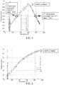
- FIGS. 1 - 3 these inaccuracies/variations are illustrated, wherein the resistance to temperature (R-T) relationship is shown for multiple uses of a particular material (each of FIGS. 1 - 3 corresponds to a different material).
- R-T resistance to temperature
- FIG. 1 a material was used having a non-monotonic relationship in which a particular resistance value corresponds to more than one temperature. For instance, 29.5 ohms corresponds to both 300°C and 790°C temperatures.
- FIG. 2 shows a resistance to temperature relationship that has shifted from one use to another.
- FIG. 3 shows non-monotonic behavior in which the same resistance is achieved at three different temperatures and also shows a resistance to temperature relationship that has shifted after use at high temperatures. Since the benefit of using resistance to measure temperature is to accurately know the heater temperature without the use of a separate temperature sensor, the illustrative effects shown in FIGS. 1 - 3 cause a two-wire control system to have significant limitations for many systems/applications.
- the present disclosure provides for a system that interprets and calibrates the relationship of resistance to temperature based on a priori and in situ information.
- Table 1 below provides examples of various types of a priori and in situ information that may be employed.
- TABLE 1 A priori In situ General Characteristic Unique Characteristic System Characteristic Product Characteristic Typical drift/shift in resistance due to time & temperature exposure
- Initial resistance - temperature characteristic Fluid mass flow Resistance at local maximum Typical hysteresis in resistance - temperature characteristic
- Room temperature resistance Typical transient rate of heating to applied power characteristic Initial dynamic power to heater temperature characteristics Ambient Temperature Resistance at other temperatures Heater lot drift/shift characteristic Temperature of various masses in the proximity of the heater Leakage current Specific transient rate of heating to applied power characteristic Power applied to heater Specific emissivity characteristic
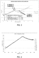
- FIG. 4 shows experimental results of over 180 cycles to a temperature of about 900°C. (Temperature was measured by an internal thermocouple in a cartridge type heater in this experiment). Additional testing has shown that after a short burn-in, with rapid heating, the local maximum typically remains within a range of 15°C even when exposed to higher temperatures that may damage the heater.
- FIG. 3 illustrates one example of this behavior, although the resistance value goes up after exposure to high temperatures, the temperature at the local maximum does not vary significantly. Although the local minimum appears to vary more than the local maximum, the apparent change may be due to the overall change in slope of the curve. The portion of the curve surrounding the local minimum may also be of use to improve resistance to temperature (R-T) interpretation and calibration.
- R-T resistance to temperature
- FIG. 3 shows three (3) resistance vs temperature curves for an 80 Nickel, 20 Chromium resistive heating element within a cartridge heater. Due to exposure to high temperatures as high as 1200°C and higher, the resistance curve has shifted. The table on the chart also shows that room temperature resistance has shifted from an initial value prior to exposure to temperature. If more accurate resistance measurements are possible, then a combination of the shift at the local maximum and the shift at another temperature could be used as a two point in situ calibration.
- FIG. 5 shows an example of how the shifted curve can be corrected by using resistance values at 200°C and the local maximum.
- a 2-point calibration depends on the ability to know a second temperature for the second point of correction. This may require an additional sensor, or may be made at room temperature. This room temperature point may be taken from a prior cooling or shutdown of the system. In diesel systems, heater inlet temperature is often available and may be used for the correction.
- R-T characteristic a variety of approaches can be used to interpret and calibrate the R-T characteristic, including but not limited to:
- the heater can operate at higher temperatures, and faster response times for the heater such that heat may be transferred more rapidly to a target, such as by way of example, the exhaust gas so that a catalyst can rise to its target temperature faster.
- control algorithms are employed that use differential equations for change in temperature over time (dT/dt).
- the control system is operable to measure voltage and current and then calculate real time power and resistance for each element above.
- a J1939 communications bus is used to provide exhaust mass flow from an engine controller and heater inlet temperature (T in ) from a sensor to a power switch, for example, a DC power switch.
- the thermal conductivity (k), or the thermal diffusivity ( ⁇ ), of an insulator is calibrated to a two-wire resistance measurement.
- the modeled sheath temperature corresponded well with the actual sheath temperature.
- T in inlet temperature
- a system can be controlled to a virtual temperature without the use of an actual temperature sensor. It should be understood that a variety of heater types and geometries can be modeled, along with using equations that compensate for effects such as radiation, among a variety of system fluctuations, while remaining within the scope of the present disclosure.
- the disclosed virtual sensing reduces the number of physical sensors based on a model-based interpretation and processing of system parameters.
- a physical sensor may still be used in the thermal system, however, the total number that may be desired is reduced by using virtual sensing.
- the virtual sensing improves the responsiveness of feedback signals or parameters used for control. More specifically, a model of the system is used to predict the system response based on available signals. Further, the accuracy of a temperature is improved in applications where the physical temperature is difficult to obtain.
- a control system 10 is shown operable for obtaining data from at least one two-wire resistive heating element of a heater through a controller and adjusting power to the heater.
- Control system 10 is operable for determining and maintaining a temperature of a resistive heating element 22 of a heating system 20 for heating fluid flow.
- Resistive heating element 22 is a two-wire resistive heating element.
- Heating assembly or heating system 20 includes at least one resistive heating element 22 but can include a plurality of resistive heating elements 22 as shown in FIG. 8 .
- Heating system 20, and thus at least one resistive heating element 22, is operatively connected to a controller 30.
- Controller 30 is adapted to obtain measurements from the at least one two-wire resistive heating element 22 and adjusting power to the heating element when comparing system data provided with the heating element measurements. Controller 30 is thus in communication with a power supply 40. This can be an engine control module (not shown) or a second controller. The power supply 40 is operatively connected to heating system 20 to adjust power and thus heat output of the resistive heating elements 22.
- model should be construed to mean an equation or set of equations, a tabulation of values representing the value of a parameter at various operating conditions, an algorithm, a computer program or a set of computer instructions, a signal conditioning device or any other device that modifies the controlled variable (e.g., power to the heater) based on predicted/projected/future conditions, wherein the prediction/projection is based on a combination of a priori and in-situ measurements.
- controlled variable e.g., power to the heater
Landscapes
- Engineering & Computer Science (AREA)
- Chemical & Material Sciences (AREA)
- Combustion & Propulsion (AREA)
- General Engineering & Computer Science (AREA)
- Mechanical Engineering (AREA)
- Chemical Kinetics & Catalysis (AREA)
- Physics & Mathematics (AREA)
- General Physics & Mathematics (AREA)
- Automation & Control Theory (AREA)
- Toxicology (AREA)
- Health & Medical Sciences (AREA)
- Ceramic Engineering (AREA)
- Power Engineering (AREA)
- Fluid Mechanics (AREA)
- Analytical Chemistry (AREA)
- Exhaust Gas After Treatment (AREA)
- Control Of Resistance Heating (AREA)
- Processes For Solid Components From Exhaust (AREA)
- Measuring Volume Flow (AREA)
- Resistance Heating (AREA)
- Combined Controls Of Internal Combustion Engines (AREA)
- Physical Or Chemical Processes And Apparatus (AREA)
- Investigating Or Analyzing Materials Using Thermal Means (AREA)
- Exhaust Gas Treatment By Means Of Catalyst (AREA)
- Measuring Temperature Or Quantity Of Heat (AREA)
- Air-Conditioning For Vehicles (AREA)
Applications Claiming Priority (2)
| Application Number | Priority Date | Filing Date | Title |
|---|---|---|---|
| US201662302482P | 2016-03-02 | 2016-03-02 | |
| PCT/US2017/020506 WO2017151960A1 (en) | 2016-03-02 | 2017-03-02 | Heater element as sensor for temperature control in transient systems |
Publications (2)
| Publication Number | Publication Date |
|---|---|
| EP3424265A1 EP3424265A1 (en) | 2019-01-09 |
| EP3424265B1 true EP3424265B1 (en) | 2020-05-27 |
Family
ID=58347961
Family Applications (10)
| Application Number | Title | Priority Date | Filing Date |
|---|---|---|---|
| EP17714046.4A Active EP3424265B1 (en) | 2016-03-02 | 2017-03-02 | Heater element as sensor for temperature control in transient systems |
| EP22150607.4A Pending EP4047193A1 (en) | 2016-03-02 | 2017-03-02 | Heater element having targeted decreasing temperature resistance characteristics |
| EP17711473.3A Withdrawn EP3423686A1 (en) | 2016-03-02 | 2017-03-02 | Thermal storage device for use in a fluid flow system |
| EP22153261.7A Ceased EP4012164A1 (en) | 2016-03-02 | 2017-03-02 | Heating system |
| EP17711471.7A Active EP3423685B1 (en) | 2016-03-02 | 2017-03-02 | Dual-purpose heater and fluid flow measurement system |
| EP17712885.7A Active EP3423687B8 (en) | 2016-03-02 | 2017-03-02 | Heater-actuated flow bypass |
| EP17712884.0A Active EP3423684B1 (en) | 2016-03-02 | 2017-03-02 | System for axial zoning of heating power |
| EP17712886.5A Withdrawn EP3423688A1 (en) | 2016-03-02 | 2017-03-02 | Susceptor for use in a fluid flow system |
| EP17712292.6A Withdrawn EP3423683A1 (en) | 2016-03-02 | 2017-03-02 | Heater element having targeted decreasing temperature resistance characteristics |
| EP17713803.9A Withdrawn EP3423689A1 (en) | 2016-03-02 | 2017-03-02 | Virtual sensing system |
Family Applications After (9)
| Application Number | Title | Priority Date | Filing Date |
|---|---|---|---|
| EP22150607.4A Pending EP4047193A1 (en) | 2016-03-02 | 2017-03-02 | Heater element having targeted decreasing temperature resistance characteristics |
| EP17711473.3A Withdrawn EP3423686A1 (en) | 2016-03-02 | 2017-03-02 | Thermal storage device for use in a fluid flow system |
| EP22153261.7A Ceased EP4012164A1 (en) | 2016-03-02 | 2017-03-02 | Heating system |
| EP17711471.7A Active EP3423685B1 (en) | 2016-03-02 | 2017-03-02 | Dual-purpose heater and fluid flow measurement system |
| EP17712885.7A Active EP3423687B8 (en) | 2016-03-02 | 2017-03-02 | Heater-actuated flow bypass |
| EP17712884.0A Active EP3423684B1 (en) | 2016-03-02 | 2017-03-02 | System for axial zoning of heating power |
| EP17712886.5A Withdrawn EP3423688A1 (en) | 2016-03-02 | 2017-03-02 | Susceptor for use in a fluid flow system |
| EP17712292.6A Withdrawn EP3423683A1 (en) | 2016-03-02 | 2017-03-02 | Heater element having targeted decreasing temperature resistance characteristics |
| EP17713803.9A Withdrawn EP3423689A1 (en) | 2016-03-02 | 2017-03-02 | Virtual sensing system |
Country Status (8)
| Country | Link |
|---|---|
| US (17) | US10648390B2 (enExample) |
| EP (10) | EP3424265B1 (enExample) |
| JP (9) | JP7091249B2 (enExample) |
| CN (8) | CN108884734B (enExample) |
| CA (7) | CA3016558C (enExample) |
| ES (3) | ES2801394T3 (enExample) |
| MX (9) | MX2018010593A (enExample) |
| WO (8) | WO2017151967A1 (enExample) |
Cited By (2)
| Publication number | Priority date | Publication date | Assignee | Title |
|---|---|---|---|---|
| DE102021113989A1 (de) | 2021-05-31 | 2022-12-01 | Purem GmbH | Abgasheizer |
| DE102021210761A1 (de) | 2021-09-27 | 2023-03-30 | Vitesco Technologies GmbH | Heizleiter zur Aufheizung eines Abgasstroms einer Verbrennungskraftmaschine |
Families Citing this family (59)
| Publication number | Priority date | Publication date | Assignee | Title |
|---|---|---|---|---|
| DE102014008284A1 (de) * | 2014-06-03 | 2015-12-03 | Diehl Metering Gmbh | Verfahren zur Bestimmung des Volumenflusses eines strömenden Mediums durch eine Messstrecke und zugeordnete Messeinrichtung |
| WO2015186295A1 (ja) * | 2014-06-06 | 2015-12-10 | パナソニックIpマネジメント株式会社 | 静電式把持検出装置 |
| US11255244B2 (en) | 2016-03-02 | 2022-02-22 | Watlow Electric Manufacturing Company | Virtual sensing system |
| MX2018010593A (es) | 2016-03-02 | 2019-08-12 | Watlow Electric Mfg | Dispositivo de almacenamiento termico para uso en un sistema de flujo de fluido. |
| TWI707141B (zh) | 2017-07-27 | 2020-10-11 | 美商瓦特洛威電子製造公司 | 感測器系統及用以測量及控制加熱器系統之效能之整合式加熱器感測器 |
| CN109893941A (zh) * | 2017-12-07 | 2019-06-18 | 南京苏曼等离子科技有限公司 | 一种低温等离子体尘雾毒废气处理系统 |
| US10557428B2 (en) * | 2018-05-25 | 2020-02-11 | GM Global Technology Operations LLC | Method and system for predictive contol of an electrially heated aftertreatment system |
| FR3081921B1 (fr) * | 2018-05-29 | 2020-12-18 | Psa Automobiles Sa | Ligne d’echappement de moteur thermique comprenant un element de chauffage amont |
| JP7081392B2 (ja) * | 2018-08-27 | 2022-06-07 | オムロン株式会社 | 温度警報システム、温度警報方法、及びプログラム |
| JP7070246B2 (ja) * | 2018-08-27 | 2022-05-18 | オムロン株式会社 | 電熱体種判別装置、電熱体種判別方法、およびプログラム |
| DE102018217169B4 (de) * | 2018-10-08 | 2021-12-23 | Vitesco Technologies GmbH | Energieoptimale erzwungene Regeneration eines Partikelfilters eines Hybridfahrzeugs |
| US10669908B1 (en) | 2018-12-03 | 2020-06-02 | Wellhead Power Solutions, Llc | Power generating systems and methods for reducing startup NOx emissions in fossile fueled power generation system |
| WO2020159991A1 (en) * | 2019-01-29 | 2020-08-06 | Watlow Electric Manufacturing Company | Virtual sensing system |
| CN113557088B (zh) * | 2019-03-22 | 2023-09-05 | 日本碍子株式会社 | 蜂窝结构体及废气净化装置 |
| US11867111B2 (en) | 2019-05-09 | 2024-01-09 | Cummins Emission Solutions Inc. | Valve arrangement for split-flow close-coupled catalyst |
| GB2619428B (en) * | 2019-05-09 | 2024-04-03 | Cummins Emission Solutions Inc | Valve arrangement for split-flow close-coupled catalyst |
| ES2941940T3 (es) | 2019-10-15 | 2023-05-26 | Vorwerk Co Interholding | Procedimiento para el funcionamiento de un sistema de calentamiento y un robot de cocina |
| CN110793777B (zh) * | 2019-10-23 | 2021-05-25 | 清华大学 | 一种模拟柴油机进气道环境进气预热效果的测试装置 |
| EP3843501B1 (en) * | 2019-12-23 | 2022-10-19 | Kanthal GmbH | Methods and systems for cooling a heating element |
| DE102020101194B4 (de) | 2020-01-20 | 2022-07-28 | Volkswagen Aktiengesellschaft | Verfahren zur Abgasnachbehandlung eines Verbrennungsmotors sowie Verbrennungsmotor |
| KR102830622B1 (ko) * | 2020-02-24 | 2025-07-07 | 와틀로 일렉트릭 매뉴팩츄어링 컴파니 | 히터를 제어하는 제어 시스템의 동적 교정 |
| US20210368584A1 (en) * | 2020-05-19 | 2021-11-25 | Watlow Electric Manufacturing Company | Passive and active calibration methods for a resistive heater |
| DE102020116169B4 (de) * | 2020-06-18 | 2025-08-14 | Volkswagen Aktiengesellschaft | Verfahren zum Betreiben eines Verbrennungsmotors sowie Kraftfahrzeug mit Verbrennungsmotor |
| TWI809475B (zh) * | 2020-08-12 | 2023-07-21 | 美商瓦特洛威電子製造公司 | 用於提供針對電氣加熱器的可變調降控制之方法及系統 |
| CN112197826A (zh) * | 2020-09-02 | 2021-01-08 | 中国空气动力研究与发展中心低速空气动力研究所 | 一种航空发动机进气质量流量测量装置及测量方法 |
| US11668488B2 (en) | 2020-09-11 | 2023-06-06 | Rheem Manufacturing Company | System and method of controlling a heat transfer system |
| CN112414911B (zh) * | 2020-09-27 | 2021-08-24 | 清华大学 | 一种燃气轮机进气过滤系统运行状态实时监测方法 |
| CN112747929B (zh) * | 2020-11-30 | 2021-11-23 | 南京航空航天大学 | 一种扩大叶栅攻角调节范围的叶栅试验台流道调节机构 |
| CN114687837A (zh) * | 2020-12-30 | 2022-07-01 | 三河市科达科技有限公司 | 柴油发动机排气后处理系统的颗粒过滤器加热装置及方法 |
| KR20230132824A (ko) | 2021-01-19 | 2023-09-18 | 와틀로 일렉트릭 매뉴팩츄어링 컴파니 | 산업 시스템들에 대한 유체 라인 누출을 검출하고 진단하기위한 방법 및 시스템 |
| DE102021200701A1 (de) | 2021-01-27 | 2022-07-28 | Robert Bosch Gesellschaft mit beschränkter Haftung | Verfahren und Vorrichtung zur Diagnose eines Katalysators mit einem elektrischen Heizer |
| CN113056044B (zh) * | 2021-03-10 | 2022-11-25 | 刘忠海 | 一种石墨烯金属网及其制备方法以及电加热带及其应用 |
| KR20220127174A (ko) * | 2021-03-10 | 2022-09-19 | 와틀로 일렉트릭 매뉴팩츄어링 컴파니 | 열적 그래디언트 보상을 위한 가상 감지를 가진 히트 번들 |
| EP4063627B1 (en) * | 2021-03-25 | 2024-12-11 | Volvo Truck Corporation | An exhaust aftertreatment arrangement for converting nox emissions |
| CN112963225B (zh) * | 2021-03-25 | 2023-02-17 | 一汽解放汽车有限公司 | 尾气加热装置及尾气处理系统 |
| CN113513652A (zh) * | 2021-04-14 | 2021-10-19 | 西安热工研究院有限公司 | 一种工业篮式管道加热装置及其加热方法 |
| DE102021109567A1 (de) * | 2021-04-16 | 2022-10-20 | Purem GmbH | Heizleiter für eine Abgasheizanordnung |
| EP4341536A1 (en) * | 2021-05-16 | 2024-03-27 | Eaton Intelligent Power Limited | Aftertreatment heater power electronics |
| EP4098853A1 (en) * | 2021-06-01 | 2022-12-07 | Volvo Truck Corporation | An exhaust aftertreatment system |
| US12128898B2 (en) * | 2021-06-02 | 2024-10-29 | Cummins Inc. | Systems and methods for reducing emissions with smart alternator |
| DE102022206430A1 (de) | 2021-06-29 | 2022-12-29 | Cummins Emission Solutions Inc. | Systeme und Verfahren zur Reduzierung der NOx-Emissionen von Nachbehandlungssystemen |
| DE102021122083A1 (de) * | 2021-08-26 | 2023-03-02 | Purem GmbH | Abgasheizer |
| DE102021122681A1 (de) * | 2021-09-02 | 2023-03-02 | Purem GmbH | Abgasheizer |
| CA3238681A1 (en) | 2021-11-22 | 2023-05-25 | Watlow Electric Manufacturing Company | Method of generating a digital twin of the environment of industrial processes |
| US12315903B2 (en) * | 2021-12-27 | 2025-05-27 | GM Global Technology Operations LLC | Thermal propagation mitigation of vehicle components |
| DE102022100696A1 (de) * | 2022-01-13 | 2023-07-13 | Bayerische Motoren Werke Aktiengesellschaft | Verfahren und Steuergerät zum Betreiben eines Dieselkraftfahrzeugs zur Emissionsreduzierung und Kraftfahrzeug |
| CN114486622B (zh) * | 2022-01-19 | 2023-10-20 | 山东交通学院 | 一种实时测量液体在不同温度下密度的实验装置及方法 |
| CN114323568B (zh) * | 2022-03-14 | 2022-07-08 | 武汉普赛斯电子技术有限公司 | 光器件的三温测试系统 |
| KR20230144270A (ko) * | 2022-04-07 | 2023-10-16 | 한온시스템 주식회사 | 유체가열 히터 및 유체가열 히터의 구동제어방법 |
| CN114856843B (zh) * | 2022-05-18 | 2023-05-23 | 潍柴动力股份有限公司 | 一种排气量计算方法、egr气量控制方法及egr系统 |
| KR102823320B1 (ko) * | 2022-06-01 | 2025-06-19 | 와틀로 일렉트릭 매뉴팩츄어링 컴파니 | 부하의 저항을 결정하는 제어기를 교정하기 위한 방법 및 시스템 |
| DE102022131601A1 (de) * | 2022-11-29 | 2024-05-29 | Friedrich Boysen GmbH & Co KG. | Heizeinrichtung zum Beheizen eines Gasstroms |
| US11828796B1 (en) | 2023-05-02 | 2023-11-28 | AEM Holdings Ltd. | Integrated heater and temperature measurement |
| US20240419198A1 (en) * | 2023-06-16 | 2024-12-19 | Saebom LEE | Intelligent temperature control method and system of heating and/or cooling apparatus |
| US12013432B1 (en) | 2023-08-23 | 2024-06-18 | Aem Singapore Pte. Ltd. | Thermal control wafer with integrated heating-sensing elements |
| US12085609B1 (en) | 2023-08-23 | 2024-09-10 | Aem Singapore Pte. Ltd. | Thermal control wafer with integrated heating-sensing elements |
| GB2636363A (en) * | 2023-12-07 | 2025-06-18 | Airbus Operations Ltd | Hydraulic actuator |
| US12000885B1 (en) | 2023-12-20 | 2024-06-04 | Aem Singapore Pte. Ltd. | Multiplexed thermal control wafer and coldplate |
| CN118188106B (zh) * | 2024-04-11 | 2025-10-31 | 奇瑞汽车股份有限公司 | 加热装置、加热装置控制方法及汽车 |
Family Cites Families (248)
| Publication number | Priority date | Publication date | Assignee | Title |
|---|---|---|---|---|
| US1366519A (en) * | 1920-03-13 | 1921-01-25 | Samuel M Carmean | Electric heater |
| US1467810A (en) | 1921-10-25 | 1923-09-11 | Westinghouse Electric & Mfg Co | High-temperature resistor material |
| US1791561A (en) | 1929-05-03 | 1931-02-10 | Surface Combustion Corp | Apparatus for heating air |
| US2091905A (en) * | 1935-09-09 | 1937-08-31 | Bensel Arlington | Electric resistance heating element |
| US2900483A (en) * | 1958-09-29 | 1959-08-18 | Gen Electric | Electric catalytic contact device |
| US3037942A (en) | 1959-11-02 | 1962-06-05 | Gen Electric | Positive temperature coefficient of resistivity resistor |
| US3176117A (en) * | 1961-03-09 | 1965-03-30 | Berko Electric Mfg Corp | Electric space heater unit |
| US3231522A (en) | 1963-09-26 | 1966-01-25 | American Radiator & Standard | Thermistor |
| US3694626A (en) * | 1971-09-30 | 1972-09-26 | Gen Electric | Electrical resistance heater |
| US4211075A (en) * | 1978-10-19 | 1980-07-08 | General Motors Corporation | Diesel engine exhaust particulate filter with intake throttling incineration control |
| JPS6032334Y2 (ja) * | 1979-12-21 | 1985-09-27 | トヨタ自動車株式会社 | 内燃機関の排気ガス中の微粒子捕集装置 |
| FR2481507A1 (fr) | 1980-04-29 | 1981-10-30 | Stein Industrie | Dispositif de reduction des contraintes thermiques dans le fond d'un echangeur de chaleur vertical |
| JPS5728214A (en) * | 1980-07-28 | 1982-02-15 | Nippon Soken Inc | Gas flow rate measuring device |
| JPS5823187A (ja) * | 1981-08-03 | 1983-02-10 | 株式会社日本自動車部品総合研究所 | セラミツク構造体およびその製造方法 |
| US4449362A (en) * | 1981-12-02 | 1984-05-22 | Robertshaw Controls Company | Exhaust system for an internal combustion engine, burn-off unit and methods therefor |
| JPS59192928A (ja) * | 1983-04-15 | 1984-11-01 | Hitachi Ltd | 薄膜最高温度計 |
| JPS6184563A (ja) | 1984-10-02 | 1986-04-30 | Honda Kogyo Kk | 流体速度測定方法及びその装置 |
| EP0186095B1 (en) * | 1984-12-26 | 1990-08-29 | Nippondenso Co., Ltd. | Anti-reducing semiconducting porcelain having a positive temperature coefficient of resistance |
| DE3538155A1 (de) * | 1985-10-26 | 1987-04-30 | Fev Forsch Energietech Verbr | Verfahren zur oxidation von in russfiltersystemen abgelagerten partikeln |
| US4808009A (en) * | 1986-06-05 | 1989-02-28 | Rosemount, Inc. | Integrated semiconductor resistance temperature sensor and resistive heater |
| US4814587A (en) * | 1986-06-10 | 1989-03-21 | Metcal, Inc. | High power self-regulating heater |
| US4744216A (en) * | 1986-10-20 | 1988-05-17 | Ford Motor Company | Electrical ignition device for regeneration of a particulate trap |
| JPH0816030B2 (ja) * | 1986-12-08 | 1996-02-21 | 日本電装株式会社 | 窒化珪素−窒化チタン系複合導電材料 |
| JPH01143202A (ja) * | 1987-11-28 | 1989-06-05 | Central Glass Co Ltd | 中高温用ptcサーミスタ |
| US5319929A (en) | 1988-05-20 | 1994-06-14 | W. R. Grace & Co.-Conn. | Catalytic converter system |
| US4878928A (en) * | 1988-07-28 | 1989-11-07 | Donaldson Company, Inc. | Apparatus for increasing regenerative filter heating element temperature |
| DE8810816U1 (de) | 1988-08-26 | 1989-12-21 | Emitec Gesellschaft für Emissionstechnologie mbH, 53797 Lohmar | Katalysator-Gehäuse, insbesondere für Startkatalysatoren, und zugehöriger Katalysator-Trägerkörper |
| JPH07118369B2 (ja) * | 1988-11-09 | 1995-12-18 | 憲親 武部 | 自己温度制御性ヒータ |
| GB2228396A (en) | 1989-02-20 | 1990-08-22 | Emaco | Electric hotplate |
| JPH04219413A (ja) | 1990-02-20 | 1992-08-10 | W R Grace & Co | 内燃機関の排気系 |
| EP0456919A3 (en) | 1990-04-16 | 1992-01-22 | W.R. Grace & Co.-Conn. | Catalytic converter system |
| US5373033A (en) | 1990-04-20 | 1994-12-13 | Sola International Holdings Limited | Casting composition |
| JPH086268Y2 (ja) * | 1990-06-15 | 1996-02-21 | オーバル機器工業株式会社 | 熱式流量計 |
| US5280422A (en) | 1990-11-05 | 1994-01-18 | Watlow/Winona, Inc. | Method and apparatus for calibrating and controlling multiple heaters |
| GB2255988B (en) | 1991-05-23 | 1994-12-07 | Feng Ping Jan | Furniture for use as a safe haven during earthquakes |
| DE4122141C2 (de) | 1991-07-04 | 1999-05-27 | Porsche Ag | Abgasleitung einer Brennkraftmaschine |
| US5259190A (en) * | 1991-08-01 | 1993-11-09 | Corning Incorporated | Heated cellular structures |
| US5393499A (en) * | 1992-06-03 | 1995-02-28 | Corning Incorporated | Heated cellular substrates |
| US5233970A (en) | 1992-07-02 | 1993-08-10 | Harmony Thermal Company, Inc. | Semi-instantaneous water heater with helical heat exchanger |
| US5465573A (en) * | 1992-07-29 | 1995-11-14 | Ngk Insulators, Ltd. | Multi-stage honeycomb heater |
| JP3058991B2 (ja) * | 1992-07-29 | 2000-07-04 | 日本碍子株式会社 | 多段ハニカムヒーターおよびその運転方法 |
| US5297518A (en) * | 1992-08-10 | 1994-03-29 | Cherry Mark A | Mass controlled compression timed ignition method and igniter |
| DE4328125B4 (de) * | 1992-08-21 | 2004-03-18 | Denso Corp., Kariya | Abgasreinigungsvorrichtung für einen Verbrennungsmotor oder dergleichen |
| US5582805A (en) * | 1992-12-21 | 1996-12-10 | Toyota Jidosha Kabushiki Kaisha | Electrically heated catalytic apparatus |
| US5444217A (en) | 1993-01-21 | 1995-08-22 | Moore Epitaxial Inc. | Rapid thermal processing apparatus for processing semiconductor wafers |
| JP3396247B2 (ja) * | 1993-02-15 | 2003-04-14 | 三菱重工業株式会社 | 排気ガス浄化装置 |
| US5738832A (en) | 1993-02-15 | 1998-04-14 | Mitsubishi Jidosha Kogyo Kabushiki Kaisha | Exhaust gas purifying apparatus |
| US5471034A (en) * | 1993-03-17 | 1995-11-28 | Texas Instruments Incorporated | Heater apparatus and process for heating a fluid stream with PTC heating elements electrically connected in series |
| US5310327A (en) | 1993-03-29 | 1994-05-10 | Reginald Phillips | Workpiece deflector shield for an injection molding apparatus |
| JPH06336915A (ja) * | 1993-05-31 | 1994-12-06 | Nissan Motor Co Ltd | 内燃機関の排気浄化装置 |
| US5716586A (en) * | 1993-06-03 | 1998-02-10 | Kabushiki Kaisha Toyoda Jidoshokki Seisakusho | Exhaust gas purifier |
| JPH0711946A (ja) * | 1993-06-29 | 1995-01-13 | Nissan Motor Co Ltd | 内燃機関の排気浄化装置 |
| JPH0754640A (ja) * | 1993-08-12 | 1995-02-28 | Mitsubishi Motors Corp | 排気浄化装置 |
| DE4339290C2 (de) * | 1993-11-18 | 1995-11-02 | Daimler Benz Ag | Verfahren zum Herstellen von Rohr-T-Stücken aus einem unverzweigt durchgehenden Ausgangsrohrstück durch Innenhochdruck-Umformung sowie Vorrichtung zur Durchführung des Verfahrens |
| JP2732031B2 (ja) * | 1994-04-28 | 1998-03-25 | 株式会社いすゞセラミックス研究所 | デイーゼル機関の排気微粒子フイルタ |
| US5582003A (en) * | 1994-04-28 | 1996-12-10 | Corning Incorporated | Temperature actuated zeolite in-line adsorber system |
| DE69502344T2 (de) * | 1994-05-17 | 1998-11-19 | Isuzu Ceramics Res Inst | Dieselpartikelfilter |
| JP3524956B2 (ja) | 1994-05-30 | 2004-05-10 | トヨタ自動車株式会社 | 電気加熱式触媒装置 |
| US5444976A (en) | 1994-06-27 | 1995-08-29 | General Motors Corporation | Catalytic converter heating |
| US5603216A (en) * | 1994-08-02 | 1997-02-18 | Corning Incorporated | By-pass adsorber system |
| JP3553146B2 (ja) * | 1994-08-22 | 2004-08-11 | 本田技研工業株式会社 | 電気加熱式触媒制御装置 |
| JPH0868310A (ja) * | 1994-08-29 | 1996-03-12 | Isuzu Ceramics Kenkyusho:Kk | ディーゼルパティキュレートフィルタ装置 |
| US5620490A (en) | 1994-08-29 | 1997-04-15 | Isuzu Ceramics Research Institute Co., Ltd. | Diesel particulate filter apparatus |
| JPH0868311A (ja) * | 1994-08-29 | 1996-03-12 | Isuzu Ceramics Kenkyusho:Kk | ディーゼルパティキュレートフィルタの構造 |
| US5651248A (en) * | 1994-08-29 | 1997-07-29 | Isuzu Ceramics Research Institute Co., Ltd. | Diesel particulate filter apparatus |
| JPH08122118A (ja) | 1994-10-20 | 1996-05-17 | Tokyo Gas Co Ltd | 熱式マイクロフローセンサ |
| US5611831A (en) * | 1994-11-16 | 1997-03-18 | Isuzu Ceramics Research Institute Co., Ltd. | Diesel particulate filter apparatus |
| JPH08193513A (ja) * | 1995-01-13 | 1996-07-30 | Calsonic Corp | 電気加熱触媒コンバータおよびその制御方法 |
| US5716133A (en) | 1995-01-17 | 1998-02-10 | Applied Komatsu Technology, Inc. | Shielded heat sensor for measuring temperature |
| JPH08284652A (ja) * | 1995-04-18 | 1996-10-29 | Toyota Motor Corp | 電気加熱式触媒の構造 |
| US5597503A (en) * | 1995-06-02 | 1997-01-28 | Corning Incorporated | Axially assembled enclosure for electrical fluid heater having a peripheral compression ring producing a diametrically balanced force |
| US5600947A (en) | 1995-07-05 | 1997-02-11 | Ford Motor Company | Method and system for estimating and controlling electrically heated catalyst temperature |
| IL118739A0 (en) | 1995-09-07 | 1996-10-16 | Bar Keser Project Management I | Electric heating devices and heating elements for use therewith |
| US6704497B2 (en) | 1995-09-07 | 2004-03-09 | Bar-Keser Project Management Initiatives And Economic Consultants (1991) Ltd. | Electric heating devices and elements |
| JPH09180907A (ja) * | 1995-10-27 | 1997-07-11 | Murata Mfg Co Ltd | 積層複合セラミックとそれを用いた積層複合セラミック素子 |
| JPH09158717A (ja) * | 1995-12-08 | 1997-06-17 | Toyota Motor Corp | 電気加熱式触媒の電力供給制御装置 |
| AU1843597A (en) | 1996-01-31 | 1997-08-22 | Asm America, Inc. | Model-based predictive control of thermal processing |
| FR2755623B1 (fr) | 1996-11-12 | 1998-12-04 | Inst Francais Du Petrole | Procede et unite de filtration de gaz d'echappement, ayant un chauffage modulable |
| US5719378A (en) * | 1996-11-19 | 1998-02-17 | Illinois Tool Works, Inc. | Self-calibrating temperature controller |
| JPH10184346A (ja) * | 1996-12-27 | 1998-07-14 | Nissan Motor Co Ltd | 内燃機関の排気浄化装置 |
| CN1047457C (zh) * | 1997-02-26 | 1999-12-15 | 清华大学 | 中低温烧结复合特性热敏电阻材料及其制备方法 |
| JP3365244B2 (ja) * | 1997-03-06 | 2003-01-08 | 松下電器産業株式会社 | 排ガス浄化装置 |
| JPH10259709A (ja) * | 1997-03-19 | 1998-09-29 | Matsushita Electric Ind Co Ltd | 排ガス浄化方法及び排ガス浄化装置 |
| DE19720205B4 (de) | 1997-05-14 | 2006-05-18 | Johannes Schedler | Anlage zur Reinigung von mit Stickoxiden beladenen Abgasen |
| JP3269012B2 (ja) | 1997-08-19 | 2002-03-25 | 株式会社椿本チエイン | モータ付減速機の減速主軸の軸方向取付け調整装置 |
| JP3331919B2 (ja) * | 1997-08-29 | 2002-10-07 | 三菱自動車工業株式会社 | 内燃機関の排気ガス浄化装置 |
| US6588268B1 (en) * | 1997-11-21 | 2003-07-08 | Mitsui Mining & Smelting Co. Ltd. | Flow rate sensor, temperature sensor and flow rate detecting apparatus |
| JPH11184346A (ja) | 1997-12-25 | 1999-07-09 | Copyer Co Ltd | 画像形成装置及び紙綴じ装置 |
| JP3658170B2 (ja) * | 1998-01-19 | 2005-06-08 | 三菱電機株式会社 | 流量センサ |
| JP2957163B1 (ja) * | 1998-05-28 | 1999-10-04 | 株式会社三五 | 排気系部品とその製造方法 |
| JP2000073747A (ja) * | 1998-06-19 | 2000-03-07 | Futaba Industrial Co Ltd | 触媒システム |
| JP2000007301A (ja) * | 1998-06-29 | 2000-01-11 | Ngk Insulators Ltd | 改質反応装置 |
| US6330910B1 (en) | 1999-03-03 | 2001-12-18 | Easton Bennett | Heat exchanger for a motor vehicle exhaust |
| US6474155B1 (en) | 1999-07-08 | 2002-11-05 | Lockheed Martin Corporation | Constant-temperature-difference flow sensor |
| US7624632B1 (en) * | 1999-08-17 | 2009-12-01 | Lockheed Martin Corporation | Constant-temperature-difference flow sensor, and integrated flow, temperature, and pressure sensor |
| US6470741B1 (en) * | 2000-06-23 | 2002-10-29 | Instrumentarium, Inc. | Hot wire anemometer gas flow sensor having improved operation and compensation |
| JP4239417B2 (ja) | 2000-07-10 | 2009-03-18 | トヨタ自動車株式会社 | 蓄熱装置付き内燃機関 |
| JP2002070531A (ja) * | 2000-08-24 | 2002-03-08 | Ibiden Co Ltd | 排気ガス浄化装置、排気ガス浄化装置のケーシング構造 |
| GB2374783A (en) * | 2000-12-15 | 2002-10-23 | Jeffery Boardman | Self regulating heating element |
| US6622558B2 (en) | 2000-11-30 | 2003-09-23 | Orbital Research Inc. | Method and sensor for detecting strain using shape memory alloys |
| JP2002227640A (ja) * | 2001-02-02 | 2002-08-14 | Sankei Kogyo Kk | 排気ガス浄化装置 |
| US6396028B1 (en) | 2001-03-08 | 2002-05-28 | Stephen J. Radmacher | Multi-layer ceramic heater |
| US6951099B2 (en) | 2001-04-03 | 2005-10-04 | John Dickau | Heated insulated catalytic converter with air cooling |
| JP3941427B2 (ja) * | 2001-07-16 | 2007-07-04 | 株式会社Sumco | 加熱装置及び加熱方法 |
| CA2463104C (en) | 2001-10-24 | 2010-12-14 | Shell Canada Limited | In situ production of a blending agent from a hydrocarbon containing formation |
| JP3748063B2 (ja) * | 2001-10-29 | 2006-02-22 | 三菱自動車工業株式会社 | 排圧上昇装置 |
| JP3824959B2 (ja) * | 2002-03-29 | 2006-09-20 | 本田技研工業株式会社 | 排ガスセンサの温度制御装置 |
| JP3538188B2 (ja) * | 2002-04-02 | 2004-06-14 | 三菱電機株式会社 | 感熱式流量検出素子およびその製造方法 |
| US6882929B2 (en) | 2002-05-15 | 2005-04-19 | Caterpillar Inc | NOx emission-control system using a virtual sensor |
| DE10225337A1 (de) * | 2002-06-06 | 2003-12-24 | Schott Glas | Kochsystem mit direkt geheizter Glaskeramikplatte |
| US7106167B2 (en) | 2002-06-28 | 2006-09-12 | Heetronix | Stable high temperature sensor system with tungsten on AlN |
| JP4503222B2 (ja) * | 2002-08-08 | 2010-07-14 | 本田技研工業株式会社 | 内燃機関の空燃比制御装置 |
| ES2274309T3 (es) * | 2002-08-30 | 2007-05-16 | The Dial Corporation | Metodo y aparato para una resistencia variable configurada para compensar la distorsion en un circuito provisto de un elemento calentador. |
| EP1416143A1 (en) | 2002-10-29 | 2004-05-06 | STMicroelectronics S.r.l. | Virtual sensor for the exhaust emissions of an endothermic motor and corresponding injection control system |
| DE10300298A1 (de) * | 2003-01-02 | 2004-07-15 | Daimlerchrysler Ag | Abgasnachbehandlungseinrichtung und -verfahren |
| US7049558B2 (en) * | 2003-01-27 | 2006-05-23 | Arcturas Bioscience, Inc. | Apparatus and method for heating microfluidic volumes and moving fluids |
| FR2851404A1 (fr) * | 2003-02-18 | 2004-08-20 | Acome Soc Coop Travailleurs | Dispositif a cable chauffant ctp comprenant un dispositif de limitation de courant |
| JP2005001449A (ja) | 2003-06-10 | 2005-01-06 | Denso Corp | 車両用冷凍サイクル装置 |
| US7196295B2 (en) | 2003-11-21 | 2007-03-27 | Watlow Electric Manufacturing Company | Two-wire layered heater system |
| US7101816B2 (en) | 2003-12-29 | 2006-09-05 | Tokyo Electron Limited | Methods for adaptive real time control of a thermal processing system |
| EP1738052B1 (en) | 2004-04-23 | 2008-04-16 | Shell International Research Maatschappij B.V. | Inhibiting reflux in a heated well of an in situ conversion system |
| US7403704B2 (en) | 2004-08-06 | 2008-07-22 | Terumo Cardiovascular Systems Corporation | Dual heating device and method |
| JP4186899B2 (ja) * | 2004-09-30 | 2008-11-26 | 株式会社日立製作所 | 排気還流制御装置 |
| US7143580B2 (en) | 2004-10-22 | 2006-12-05 | Detroit Diesel Corporation | Virtual compressor outlet temperature sensing for charge air cooler overheating protection |
| DE102004052107B4 (de) * | 2004-10-26 | 2007-03-15 | J. Eberspächer GmbH & Co. KG | Abgasanlage und zugehöriges Betriebsverfahren |
| KR100611606B1 (ko) * | 2004-11-15 | 2006-08-10 | 한국전기연구원 | 마이크로파 반사기를 이용한 디젤 매연 필터 시스템 |
| US20060177358A1 (en) * | 2005-02-07 | 2006-08-10 | Tzong-Yih Lee | Active catalytic converter |
| WO2006087555A1 (en) | 2005-02-16 | 2006-08-24 | Imi Vision Limited | Exhaust gas treatment |
| US7251929B2 (en) | 2005-07-07 | 2007-08-07 | Eaton Corporation | Thermal management of hybrid LNT/SCR aftertreatment during desulfation |
| US7495467B2 (en) | 2005-12-15 | 2009-02-24 | Lattice Semiconductor Corporation | Temperature-independent, linear on-chip termination resistance |
| US7243538B1 (en) * | 2005-12-22 | 2007-07-17 | Honeywell International Inc. | Gas flow sensor system and method of self-calibration |
| WO2007105815A1 (en) * | 2006-03-16 | 2007-09-20 | Toyota Jidosha Kabushiki Kaisha | Exhaust gas heat recovery device |
| EP2000639B2 (en) | 2006-03-30 | 2019-08-21 | Umicore Shokubai Japan Co., Ltd. | Method of purifying exhaust gas from internal combustion engine |
| US8117832B2 (en) * | 2006-06-19 | 2012-02-21 | Donaldson Company, Inc. | Exhaust treatment device with electric regeneration system |
| JP4535036B2 (ja) | 2006-07-12 | 2010-09-01 | トヨタ自動車株式会社 | 内燃機関の電源システム |
| DE102006032698A1 (de) * | 2006-07-14 | 2008-01-24 | Bleckmann Gmbh & Co. Kg | Vorrichtung und Verfahren zur Steuerung und Absicherung eines Heizelements |
| US8209960B2 (en) | 2006-07-21 | 2012-07-03 | International Engine Intellectual Property Company, Llc | System and method for coupled DPF regeneration and LNT DeNOx |
| US7434387B2 (en) | 2006-07-26 | 2008-10-14 | Eaton Corporation | Integrated DPF-reformer |
| JP4341651B2 (ja) * | 2006-07-28 | 2009-10-07 | 株式会社日立製作所 | 熱式ガス流量計 |
| US8762097B2 (en) | 2006-08-04 | 2014-06-24 | Apple Inc. | Method and apparatus for a thermal control system based on virtual temperature sensor |
| JP2008038827A (ja) * | 2006-08-09 | 2008-02-21 | Calsonic Kansei Corp | エンジン即暖システムの制御方法 |
| US7554063B2 (en) * | 2006-08-22 | 2009-06-30 | Dimplex North America Limited | Heating apparatus |
| US7631491B2 (en) | 2006-11-15 | 2009-12-15 | Detroit Diesel Corporation | Method and system for passive regeneration of compression ignition engine exhaust filters |
| GB0700079D0 (en) * | 2007-01-04 | 2007-02-07 | Boardman Jeffrey | A method of producing electrical resistance elements whihc have self-regulating power output characteristics by virtue of their configuration and the material |
| JP2008180185A (ja) * | 2007-01-26 | 2008-08-07 | Hitachi Ltd | エンジンの排気還流制御装置 |
| US7757482B2 (en) * | 2007-02-21 | 2010-07-20 | Gm Global Technology Operations, Inc. | Variable geometry exhaust cooler |
| CN101636555A (zh) | 2007-03-22 | 2010-01-27 | 埃克森美孚上游研究公司 | 用于原位地层加热的电阻加热器 |
| DE102007025419A1 (de) | 2007-05-31 | 2008-12-04 | Emitec Gesellschaft Für Emissionstechnologie Mbh | Verfahren zum Betrieb eines Kraftfahrzeuges mit einer Abgas-Heizvorrichtung |
| US8037673B2 (en) * | 2007-06-18 | 2011-10-18 | GM Global Technology Operations LLC | Selective catalyst reduction light-off strategy |
| JP2009058501A (ja) * | 2007-08-08 | 2009-03-19 | Yamaha Motor Co Ltd | ガスセンサ、空燃比制御装置および輸送機器 |
| US8057581B2 (en) * | 2007-08-31 | 2011-11-15 | GM Global Technology Operations LLC | Zoned electrical heater arranged in spaced relationship from particulate filter |
| US8083839B2 (en) * | 2007-09-13 | 2011-12-27 | GM Global Technology Operations LLC | Radiant zone heated particulate filter |
| US8112990B2 (en) | 2007-09-14 | 2012-02-14 | GM Global Technology Operations LLC | Low exhaust temperature electrically heated particulate matter filter system |
| US8252077B2 (en) * | 2007-09-17 | 2012-08-28 | GM Global Technology Operations LLC | Electrically heated particulate filter heater insulation |
| US8292987B2 (en) * | 2007-09-18 | 2012-10-23 | GM Global Technology Operations LLC | Inductively heated particulate matter filter regeneration control system |
| JP5210588B2 (ja) * | 2007-10-03 | 2013-06-12 | 日立オートモティブシステムズ株式会社 | 熱式流量計、熱式流量計の制御方法、及び熱式流量計のセンサ素子 |
| US8146350B2 (en) | 2007-10-04 | 2012-04-03 | GM Global Technology Operations LLC | Variable power distribution for zoned regeneration of an electrically heated particulate filter |
| US8061123B2 (en) * | 2007-10-30 | 2011-11-22 | Caterpillar Inc. | Method and system of thermal management in an exhaust system |
| US20090205588A1 (en) * | 2008-02-15 | 2009-08-20 | Bilezikjian John P | Internal combustion engine with variable speed coolant pump |
| JP5004842B2 (ja) * | 2008-03-25 | 2012-08-22 | 三井造船株式会社 | 誘導加熱装置 |
| JP2009236792A (ja) | 2008-03-28 | 2009-10-15 | Hitachi Ltd | 熱式ガス流量計 |
| ATE467329T1 (de) * | 2008-03-28 | 2010-05-15 | Braun Gmbh | Heizelement mit temperatursensor |
| GB2460833B (en) * | 2008-06-09 | 2011-05-18 | 2D Heat Ltd | A self-regulating electrical resistance heating element |
| US8121744B2 (en) * | 2008-06-20 | 2012-02-21 | GM Global Technology Operations LLC | Control system and method for oxygen sensor heater control |
| JP2010025104A (ja) * | 2008-07-16 | 2010-02-04 | Borgwarner Inc | 後処理装置の受動的暖機制御用熱操作バイパス弁 |
| US8112989B1 (en) * | 2008-07-23 | 2012-02-14 | Hrl Laboratories, Llc | Electrically resistive coating for remediation (regeneration) of a diesel particulate filter and method |
| DE102008035562A1 (de) | 2008-07-30 | 2010-02-04 | Emitec Gesellschaft Für Emissionstechnologie Mbh | Abgasreinigungssystem für Dieselmotoren von Nutzkraftfahrzeugen |
| US8646257B2 (en) * | 2008-09-10 | 2014-02-11 | Mack Trucks, Inc. | Method for estimating soot loading in a diesel particulate filter, and engine and aftertreatment system |
| GB0817082D0 (en) | 2008-09-18 | 2008-10-29 | Heat Trace Ltd | Heating cable |
| US8652259B2 (en) | 2008-10-09 | 2014-02-18 | Silevo, Inc. | Scalable, high-throughput, multi-chamber epitaxial reactor for silicon deposition |
| US9345067B2 (en) * | 2008-10-13 | 2016-05-17 | ECG Operating Company LLC | Temperature monitoring and control system for negative temperature coefficient heaters |
| US8247747B2 (en) * | 2008-10-30 | 2012-08-21 | Xaloy, Inc. | Plasticating barrel with integrated exterior heater layer |
| US8166752B2 (en) * | 2008-11-26 | 2012-05-01 | GM Global Technology Operations LLC | Apparatus and method for cooling an exhaust gas |
| US8844270B2 (en) | 2009-01-16 | 2014-09-30 | Donaldson Company, Inc. | Diesel particulate filter regeneration system including shore station |
| US8097066B2 (en) * | 2009-05-13 | 2012-01-17 | GM Global Technology Operations LLC | Predicting ash loading using an electrically heated particulate filter |
| DE102009003091A1 (de) * | 2009-05-14 | 2010-11-18 | Robert Bosch Gmbh | Verfahren und Vorrichtung zur Überwachung eines in einem Abgasbereich einer Brennkraftmaschine angeordneten Bauteils |
| US8141350B2 (en) * | 2009-06-02 | 2012-03-27 | GM Global Technology Operations LLC | Electrically heated particulate filter incomplete regeneration identification system and method |
| GB2470941A (en) * | 2009-06-11 | 2010-12-15 | Univ Glasgow | Measurement of mass flow |
| US8979450B2 (en) | 2009-06-22 | 2015-03-17 | Telair International Gmbh | Function element, method for producing a function element |
| JP2011011933A (ja) | 2009-06-30 | 2011-01-20 | Hitachi Automotive Systems Ltd | 耐熱性及び耐食性を有するガラス |
| US7829048B1 (en) * | 2009-08-07 | 2010-11-09 | Gm Global Technology Operations, Inc. | Electrically heated catalyst control system and method |
| US8359844B2 (en) * | 2009-08-07 | 2013-01-29 | GM Global Technology Operations LLC | Radiant heating systems and methods for catalysts of exhaust treatment systems |
| US9410458B2 (en) | 2009-10-01 | 2016-08-09 | GM Global Technology Operations LLC | State of charge catalyst heating strategy |
| CN201555357U (zh) | 2009-11-06 | 2010-08-18 | 福州闽海药业有限公司 | 一种管道加热装置 |
| JP2011149314A (ja) * | 2010-01-20 | 2011-08-04 | Toyota Motor Corp | ハイブリッドシステムの制御装置 |
| US8453431B2 (en) | 2010-03-02 | 2013-06-04 | GM Global Technology Operations LLC | Engine-out NOx virtual sensor for an internal combustion engine |
| US8863505B2 (en) * | 2010-04-26 | 2014-10-21 | GM Global Technology Operations LLC | Start-stop hybrid exothermic catalyst heating system |
| US8188832B2 (en) * | 2010-05-05 | 2012-05-29 | State Of The Art, Inc. | Near zero TCR resistor configurations |
| US8146352B2 (en) | 2010-05-12 | 2012-04-03 | Ford Global Technologies, Llc | Diesel particulate filter control |
| US8756924B2 (en) * | 2010-05-19 | 2014-06-24 | GM Global Technology Operations LLC | Hybrid catalyst convective preheating system |
| WO2011151738A1 (en) | 2010-06-03 | 2011-12-08 | Koninklijke Philips Electronics N.V. | Passively heated patient circuit |
| CN101962294A (zh) * | 2010-07-15 | 2011-02-02 | 上海大学 | 一种w型中低温ntc-ptc双重复合热敏电阻材料及其制备方法 |
| EP3421980A3 (en) | 2010-07-22 | 2019-03-27 | Watlow Electric Manufacturing Company | Combination fluid sensor system |
| DE102010038361A1 (de) | 2010-07-23 | 2012-01-26 | Robert Bosch Gmbh | Verfahren zur Messung der Temperatur eines Mediums und Temperatursensor |
| WO2012024211A1 (en) | 2010-08-19 | 2012-02-23 | Dow Global Technologies Llc. | Method and devices for heating urea-containing materials in vehicle emission control system |
| JP5765609B2 (ja) * | 2010-10-04 | 2015-08-19 | 株式会社リコー | 電気素子、集積素子、電子回路及び温度較正装置 |
| KR101251518B1 (ko) | 2010-12-09 | 2013-04-05 | 기아자동차주식회사 | 차량의 배기가스 후처리 시스템용 도징 모듈 |
| US9605906B2 (en) | 2010-12-16 | 2017-03-28 | Denso International America Inc. | Automotive heat recovery system |
| DE102010056281A1 (de) * | 2010-12-24 | 2012-06-28 | Volkswagen Ag | Abgasanlage mit HC-Adsorber und parallelem Abgaskatalysator sowie Fahrzeug mit einer solchen Abgasanlage |
| US9062584B2 (en) | 2010-12-31 | 2015-06-23 | Cummins, Inc. | Hybrid engine aftertreatment thermal management strategy |
| DE102011009619A1 (de) | 2011-01-28 | 2012-08-02 | Emitec Gesellschaft Für Emissionstechnologie Mbh | Verfahren zum Betrieb einer Abgasanlage |
| WO2012109126A1 (en) | 2011-02-08 | 2012-08-16 | Dow Global Technologies Llc | System and method for reducing emissions from a combustion process |
| EP2674209B1 (en) * | 2011-02-08 | 2015-10-07 | Toyota Jidosha Kabushiki Kaisha | Electric heating catalyst |
| US20120204540A1 (en) * | 2011-02-14 | 2012-08-16 | GM Global Technology Operations LLC | Power system and method for energizing an electrically heated catalyst |
| JP2012225163A (ja) * | 2011-04-15 | 2012-11-15 | Toyota Motor Corp | Ehc制御方法及び同方法を使用する排気ガス浄化システム |
| GB2491411B (en) | 2011-06-03 | 2015-05-27 | Perkins Engines Co Ltd | Exhaust after treatment device mode regulation |
| US8793004B2 (en) | 2011-06-15 | 2014-07-29 | Caterpillar Inc. | Virtual sensor system and method for generating output parameters |
| US8627654B2 (en) * | 2011-08-02 | 2014-01-14 | GM Global Technology Operations LLC | Method of treating emissions of a hybrid vehicle with a hydrocarbon absorber and a catalyst bypass system |
| AU2012301936A1 (en) | 2011-08-30 | 2014-03-27 | Watlow Electric Manufacturing Company | System and method for controlling a thermal array |
| US9212422B2 (en) | 2011-08-31 | 2015-12-15 | Alta Devices, Inc. | CVD reactor with gas flow virtual walls |
| US9400197B2 (en) * | 2011-09-19 | 2016-07-26 | The Regents Of The University Of Michigan | Fluid flow sensor |
| WO2013063262A1 (en) * | 2011-10-25 | 2013-05-02 | Hydrotech, Inc | Pump monitoring device |
| AT512193B1 (de) * | 2011-11-24 | 2013-10-15 | Avl List Gmbh | Brennkraftmaschine mit einem abgassystem |
| EP2626528B1 (en) | 2011-11-30 | 2016-10-26 | Toyota Jidosha Kabushiki Kaisha | Exhaust purification device for internal combustion engine |
| EP2623738B1 (en) | 2011-11-30 | 2019-08-21 | Toyota Jidosha Kabushiki Kaisha | NOx purification method of an exhaust purification system of an internal combustion engine |
| DE102011120899B4 (de) * | 2011-12-12 | 2015-08-20 | Karlsruher Institut für Technologie | Verfahren und Verwendung einer Vorrichtung zur Bestimmung des Massenstroms eines Fluids |
| US20130199751A1 (en) | 2012-02-03 | 2013-08-08 | Ford Global Technologies, Llc | Heat storage device for an engine |
| JP6018646B2 (ja) | 2012-02-22 | 2016-11-02 | ワトロー エレクトリック マニュファクチャリング カンパニー | ヒータ制御モジュール |
| GB201204170D0 (en) * | 2012-03-09 | 2012-04-25 | Bio Nano Consulting | Cross-linked graphene networks |
| US20130239554A1 (en) | 2012-03-19 | 2013-09-19 | GM Global Technology Operations LLC | Exhaust gas treatment system having a solid ammonia gas producing material |
| US8661800B2 (en) * | 2012-04-09 | 2014-03-04 | Ford Global Technologies, Llc | Method of collection and reuse of exhaust heat in a diesel-powered vehicle |
| US9178129B2 (en) * | 2012-10-15 | 2015-11-03 | The Trustees Of The Stevens Institute Of Technology | Graphene-based films in sensor applications |
| JP5775503B2 (ja) | 2012-10-26 | 2015-09-09 | 株式会社豊田自動織機 | 蓄熱装置 |
| DE102013105992A1 (de) * | 2012-12-14 | 2014-07-03 | Endress + Hauser Flowtec Ag | Thermische Durchflussmessvorrichtung und Verfahren zur Bestimmung und/oder Überwachung eines Durchflusses eines Mediums |
| JP5660115B2 (ja) | 2012-12-18 | 2015-01-28 | 株式会社村田製作所 | ヘテロ接合バイポーラトランジスタ、これを用いた電力増幅器、及びヘテロ接合バイポーラトランジスタの製造方法 |
| CA2894700C (en) * | 2012-12-18 | 2017-03-14 | Watlow Electric Manufacturing Company | Improved exhaust gas heating apparatus |
| US20140343747A1 (en) | 2013-04-26 | 2014-11-20 | Watlow Electric Manufacturing Company | Smart heater system |
| JP2015068266A (ja) * | 2013-09-30 | 2015-04-13 | いすゞ自動車株式会社 | 排気ガス浄化システム及び排気ガス浄化方法 |
| US9169751B2 (en) | 2013-10-02 | 2015-10-27 | Ford Global Technologies, Llc | Methods and systems for utilizing waste heat for a hybrid vehicle |
| US9587546B2 (en) | 2013-10-02 | 2017-03-07 | Ford Global Technologies, Llc | Methods and systems for hybrid vehicle waste heat recovery |
| JP6131821B2 (ja) | 2013-10-22 | 2017-05-24 | トヨタ自動車株式会社 | 内燃機関の排気浄化装置 |
| JP6321946B2 (ja) * | 2013-11-18 | 2018-05-09 | 日本精線株式会社 | 触媒反応システム及び触媒反応装置 |
| US9670843B2 (en) | 2013-11-25 | 2017-06-06 | General Electric Company | System and method for heating a catalyst in an exhaust treatment system of a turbine engine |
| FR3014136B1 (fr) | 2013-12-03 | 2018-04-20 | Faurecia Systemes D'echappement | Dispositif d'injection d'un reducteur et ligne d'echappement correspondante |
| JP5680178B1 (ja) * | 2013-12-26 | 2015-03-04 | 三菱電機株式会社 | 流量センサおよび内燃機関の制御システム |
| JP6142852B2 (ja) | 2014-07-18 | 2017-06-07 | トヨタ自動車株式会社 | 流体温度制御装置 |
| JP6390560B2 (ja) * | 2014-10-01 | 2018-09-19 | 株式会社デンソー | ガス濃度検出装置 |
| JP6485364B2 (ja) * | 2015-02-12 | 2019-03-20 | 株式会社デンソー | ガスセンサ |
| DE102016101246A1 (de) * | 2015-11-02 | 2017-05-04 | Epcos Ag | Sensoranordnung und Verfahren zur Herstellung einer Sensoranordnung |
| US11255244B2 (en) * | 2016-03-02 | 2022-02-22 | Watlow Electric Manufacturing Company | Virtual sensing system |
| EP3933293A1 (en) * | 2016-03-02 | 2022-01-05 | Watlow Electric Manufacturing Company | Bare heating elements for heating fluid flows |
| US20210190380A1 (en) * | 2016-03-02 | 2021-06-24 | Watlow Electric Manufacturing Company | Heater bundles having virtual sensing for thermal gradient compensation |
| MX2018010593A (es) * | 2016-03-02 | 2019-08-12 | Watlow Electric Mfg | Dispositivo de almacenamiento termico para uso en un sistema de flujo de fluido. |
| FR3057020B1 (fr) | 2016-10-03 | 2020-09-11 | Peugeot Citroen Automobiles Sa | Dispositif de post-traitement des gaz d’echappement d’un moteur thermique |
| JP6614187B2 (ja) | 2017-03-22 | 2019-12-04 | トヨタ自動車株式会社 | 内燃機関の排気浄化装置 |
| JP2019086396A (ja) * | 2017-11-07 | 2019-06-06 | 株式会社デンソー | 制御装置 |
| GB202015521D0 (en) * | 2020-09-30 | 2020-11-11 | Circletech Ltd | Gas flow sensor assembly, method of forming a semiconductor gas flow sensor, a semiconductor gas flow sensor |
| US11946400B2 (en) * | 2021-10-19 | 2024-04-02 | Paccar Inc | System and method for monitoring an oxidation catalyst |
-
2017
- 2017-03-02 MX MX2018010593A patent/MX2018010593A/es unknown
- 2017-03-02 MX MX2018010597A patent/MX392054B/es unknown
- 2017-03-02 CN CN201780017115.3A patent/CN108884734B/zh active Active
- 2017-03-02 JP JP2018545992A patent/JP7091249B2/ja active Active
- 2017-03-02 EP EP17714046.4A patent/EP3424265B1/en active Active
- 2017-03-02 US US15/448,044 patent/US10648390B2/en active Active
- 2017-03-02 EP EP22150607.4A patent/EP4047193A1/en active Pending
- 2017-03-02 JP JP2018545969A patent/JP2019512634A/ja active Pending
- 2017-03-02 CN CN201780017087.5A patent/CN108884738B/zh active Active
- 2017-03-02 MX MX2018010595A patent/MX385057B/es unknown
- 2017-03-02 WO PCT/US2017/020515 patent/WO2017151967A1/en not_active Ceased
- 2017-03-02 CA CA3016558A patent/CA3016558C/en active Active
- 2017-03-02 EP EP17711473.3A patent/EP3423686A1/en not_active Withdrawn
- 2017-03-02 US US15/448,068 patent/US10724417B2/en active Active
- 2017-03-02 US US15/447,994 patent/US10760465B2/en active Active
- 2017-03-02 JP JP2018545972A patent/JP6980676B2/ja not_active Expired - Fee Related
- 2017-03-02 CA CA3016553A patent/CA3016553A1/en active Pending
- 2017-03-02 MX MX2018010592A patent/MX391690B/es unknown
- 2017-03-02 JP JP2018545962A patent/JP6853264B2/ja active Active
- 2017-03-02 JP JP2018545959A patent/JP6921840B2/ja active Active
- 2017-03-02 US US15/448,130 patent/US20170254241A1/en not_active Abandoned
- 2017-03-02 CA CA3016547A patent/CA3016547C/en active Active
- 2017-03-02 EP EP22153261.7A patent/EP4012164A1/en not_active Ceased
- 2017-03-02 EP EP17711471.7A patent/EP3423685B1/en active Active
- 2017-03-02 CA CA3016540A patent/CA3016540C/en active Active
- 2017-03-02 MX MX2018010596A patent/MX383783B/es unknown
- 2017-03-02 MX MX2018010594A patent/MX384891B/es unknown
- 2017-03-02 CA CA3016328A patent/CA3016328C/en active Active
- 2017-03-02 CA CA3016541A patent/CA3016541A1/en active Pending
- 2017-03-02 WO PCT/US2017/020511 patent/WO2017151965A1/en not_active Ceased
- 2017-03-02 WO PCT/US2017/020506 patent/WO2017151960A1/en not_active Ceased
- 2017-03-02 EP EP17712885.7A patent/EP3423687B8/en active Active
- 2017-03-02 EP EP17712884.0A patent/EP3423684B1/en active Active
- 2017-03-02 US US15/447,964 patent/US10934921B2/en active Active
- 2017-03-02 EP EP17712886.5A patent/EP3423688A1/en not_active Withdrawn
- 2017-03-02 WO PCT/US2017/020504 patent/WO2017151959A1/en not_active Ceased
- 2017-03-02 ES ES17712884T patent/ES2801394T3/es active Active
- 2017-03-02 ES ES17711471T patent/ES2847204T3/es active Active
- 2017-03-02 EP EP17712292.6A patent/EP3423683A1/en not_active Withdrawn
- 2017-03-02 CN CN201780017844.9A patent/CN108884742B/zh active Active
- 2017-03-02 WO PCT/US2017/020520 patent/WO2017151972A1/en not_active Ceased
- 2017-03-02 WO PCT/US2017/020513 patent/WO2017151966A1/en not_active Ceased
- 2017-03-02 US US15/448,108 patent/US10470247B2/en active Active
- 2017-03-02 CN CN201780018445.4A patent/CN108886835B/zh active Active
- 2017-03-02 ES ES17714046T patent/ES2805046T3/es active Active
- 2017-03-02 JP JP2018545967A patent/JP6987773B2/ja active Active
- 2017-03-02 CN CN201780022735.6A patent/CN108884735B/zh active Active
- 2017-03-02 WO PCT/US2017/020516 patent/WO2017151968A2/en not_active Ceased
- 2017-03-02 WO PCT/US2017/020518 patent/WO2017151970A1/en not_active Ceased
- 2017-03-02 US US15/447,942 patent/US10544722B2/en active Active
- 2017-03-02 CN CN201780017101.1A patent/CN108884739B/zh active Active
- 2017-03-02 MX MX2018010598A patent/MX383965B/es unknown
- 2017-03-02 CN CN201780018449.2A patent/CN108925139B/zh active Active
- 2017-03-02 MX MX2018010599A patent/MX2018010599A/es unknown
- 2017-03-02 CA CA3016319A patent/CA3016319C/en active Active
- 2017-03-02 JP JP2018545968A patent/JP7051696B2/ja active Active
- 2017-03-02 US US15/448,162 patent/US10975750B2/en active Active
- 2017-03-02 EP EP17713803.9A patent/EP3423689A1/en not_active Withdrawn
- 2017-03-02 CN CN202210031673.8A patent/CN114458431B/zh active Active
-
2018
- 2018-08-31 MX MX2020001915A patent/MX2020001915A/es unknown
- 2018-10-17 US US16/162,441 patent/US10815858B2/en active Active
-
2019
- 2019-12-11 US US16/710,119 patent/US11970964B2/en active Active
-
2020
- 2020-05-11 US US16/871,914 patent/US11028759B2/en active Active
- 2020-05-27 US US16/884,771 patent/US12037933B2/en active Active
- 2020-05-27 US US16/884,853 patent/US11340121B2/en active Active
- 2020-08-10 US US16/989,217 patent/US11486291B2/en active Active
-
2021
- 2021-12-01 JP JP2021195296A patent/JP2022043087A/ja active Pending
-
2022
- 2022-02-02 JP JP2022014971A patent/JP7238176B2/ja active Active
- 2022-09-02 US US17/902,243 patent/US11795857B2/en active Active
-
2024
- 2024-04-29 US US18/649,383 patent/US12258898B2/en active Active
- 2024-06-14 US US18/743,426 patent/US12326107B2/en active Active
Non-Patent Citations (1)
| Title |
|---|
| None * |
Cited By (2)
| Publication number | Priority date | Publication date | Assignee | Title |
|---|---|---|---|---|
| DE102021113989A1 (de) | 2021-05-31 | 2022-12-01 | Purem GmbH | Abgasheizer |
| DE102021210761A1 (de) | 2021-09-27 | 2023-03-30 | Vitesco Technologies GmbH | Heizleiter zur Aufheizung eines Abgasstroms einer Verbrennungskraftmaschine |
Also Published As
Similar Documents
| Publication | Publication Date | Title |
|---|---|---|
| EP3424265B1 (en) | Heater element as sensor for temperature control in transient systems | |
| CN101685044B (zh) | 基于温度传感器读数对瞬态条件下气体温度的准确估计 | |
| US10545054B2 (en) | Active grounded thermocouple and method of operation |
Legal Events
| Date | Code | Title | Description |
|---|---|---|---|
| STAA | Information on the status of an ep patent application or granted ep patent |
Free format text: STATUS: UNKNOWN |
|
| STAA | Information on the status of an ep patent application or granted ep patent |
Free format text: STATUS: THE INTERNATIONAL PUBLICATION HAS BEEN MADE |
|
| PUAI | Public reference made under article 153(3) epc to a published international application that has entered the european phase |
Free format text: ORIGINAL CODE: 0009012 |
|
| STAA | Information on the status of an ep patent application or granted ep patent |
Free format text: STATUS: REQUEST FOR EXAMINATION WAS MADE |
|
| 17P | Request for examination filed |
Effective date: 20180912 |
|
| AK | Designated contracting states |
Kind code of ref document: A1 Designated state(s): AL AT BE BG CH CY CZ DE DK EE ES FI FR GB GR HR HU IE IS IT LI LT LU LV MC MK MT NL NO PL PT RO RS SE SI SK SM TR |
|
| AX | Request for extension of the european patent |
Extension state: BA ME |
|
| DAV | Request for validation of the european patent (deleted) | ||
| DAX | Request for extension of the european patent (deleted) | ||
| GRAP | Despatch of communication of intention to grant a patent |
Free format text: ORIGINAL CODE: EPIDOSNIGR1 |
|
| STAA | Information on the status of an ep patent application or granted ep patent |
Free format text: STATUS: GRANT OF PATENT IS INTENDED |
|
| RIC1 | Information provided on ipc code assigned before grant |
Ipc: G01K 7/16 20060101ALI20191112BHEP Ipc: H05B 3/40 20060101ALI20191112BHEP Ipc: F01N 3/10 20060101ALI20191112BHEP Ipc: F01N 3/20 20060101ALI20191112BHEP Ipc: H05B 3/18 20060101ALI20191112BHEP Ipc: H05B 3/20 20060101ALI20191112BHEP Ipc: G01F 1/68 20060101ALI20191112BHEP Ipc: F02D 41/22 20060101ALI20191112BHEP Ipc: H05B 3/14 20060101ALI20191112BHEP Ipc: F01N 3/027 20060101ALI20191112BHEP Ipc: F02D 41/02 20060101ALI20191112BHEP Ipc: H05B 3/12 20060101ALI20191112BHEP Ipc: F02D 41/14 20060101ALI20191112BHEP Ipc: H05B 1/02 20060101AFI20191112BHEP Ipc: G05D 23/185 20060101ALI20191112BHEP Ipc: F01N 3/00 20060101ALI20191112BHEP Ipc: F01N 11/00 20060101ALI20191112BHEP Ipc: F01N 13/00 20100101ALI20191112BHEP |
|
| INTG | Intention to grant announced |
Effective date: 20191205 |
|
| GRAJ | Information related to disapproval of communication of intention to grant by the applicant or resumption of examination proceedings by the epo deleted |
Free format text: ORIGINAL CODE: EPIDOSDIGR1 |
|
| STAA | Information on the status of an ep patent application or granted ep patent |
Free format text: STATUS: REQUEST FOR EXAMINATION WAS MADE |
|
| GRAJ | Information related to disapproval of communication of intention to grant by the applicant or resumption of examination proceedings by the epo deleted |
Free format text: ORIGINAL CODE: EPIDOSDIGR1 |
|
| GRAP | Despatch of communication of intention to grant a patent |
Free format text: ORIGINAL CODE: EPIDOSNIGR1 |
|
| GRAR | Information related to intention to grant a patent recorded |
Free format text: ORIGINAL CODE: EPIDOSNIGR71 |
|
| GRAS | Grant fee paid |
Free format text: ORIGINAL CODE: EPIDOSNIGR3 |
|
| STAA | Information on the status of an ep patent application or granted ep patent |
Free format text: STATUS: GRANT OF PATENT IS INTENDED |
|
| GRAA | (expected) grant |
Free format text: ORIGINAL CODE: 0009210 |
|
| STAA | Information on the status of an ep patent application or granted ep patent |
Free format text: STATUS: THE PATENT HAS BEEN GRANTED |
|
| INTC | Intention to grant announced (deleted) | ||
| AK | Designated contracting states |
Kind code of ref document: B1 Designated state(s): AL AT BE BG CH CY CZ DE DK EE ES FI FR GB GR HR HU IE IS IT LI LT LU LV MC MK MT NL NO PL PT RO RS SE SI SK SM TR |
|
| INTG | Intention to grant announced |
Effective date: 20200420 |
|
| REG | Reference to a national code |
Ref country code: GB Ref legal event code: FG4D |
|
| REG | Reference to a national code |
Ref country code: CH Ref legal event code: EP |
|
| REG | Reference to a national code |
Ref country code: AT Ref legal event code: REF Ref document number: 1275959 Country of ref document: AT Kind code of ref document: T Effective date: 20200615 |
|
| REG | Reference to a national code |
Ref country code: DE Ref legal event code: R096 Ref document number: 602017017295 Country of ref document: DE |
|
| REG | Reference to a national code |
Ref country code: NL Ref legal event code: FP |
|
| REG | Reference to a national code |
Ref country code: LT Ref legal event code: MG4D |
|
| PG25 | Lapsed in a contracting state [announced via postgrant information from national office to epo] |
Ref country code: GR Free format text: LAPSE BECAUSE OF FAILURE TO SUBMIT A TRANSLATION OF THE DESCRIPTION OR TO PAY THE FEE WITHIN THE PRESCRIBED TIME-LIMIT Effective date: 20200828 Ref country code: FI Free format text: LAPSE BECAUSE OF FAILURE TO SUBMIT A TRANSLATION OF THE DESCRIPTION OR TO PAY THE FEE WITHIN THE PRESCRIBED TIME-LIMIT Effective date: 20200527 Ref country code: LT Free format text: LAPSE BECAUSE OF FAILURE TO SUBMIT A TRANSLATION OF THE DESCRIPTION OR TO PAY THE FEE WITHIN THE PRESCRIBED TIME-LIMIT Effective date: 20200527 Ref country code: IS Free format text: LAPSE BECAUSE OF FAILURE TO SUBMIT A TRANSLATION OF THE DESCRIPTION OR TO PAY THE FEE WITHIN THE PRESCRIBED TIME-LIMIT Effective date: 20200927 Ref country code: NO Free format text: LAPSE BECAUSE OF FAILURE TO SUBMIT A TRANSLATION OF THE DESCRIPTION OR TO PAY THE FEE WITHIN THE PRESCRIBED TIME-LIMIT Effective date: 20200827 Ref country code: SE Free format text: LAPSE BECAUSE OF FAILURE TO SUBMIT A TRANSLATION OF THE DESCRIPTION OR TO PAY THE FEE WITHIN THE PRESCRIBED TIME-LIMIT Effective date: 20200527 Ref country code: PT Free format text: LAPSE BECAUSE OF FAILURE TO SUBMIT A TRANSLATION OF THE DESCRIPTION OR TO PAY THE FEE WITHIN THE PRESCRIBED TIME-LIMIT Effective date: 20200928 |
|
| PG25 | Lapsed in a contracting state [announced via postgrant information from national office to epo] |
Ref country code: HR Free format text: LAPSE BECAUSE OF FAILURE TO SUBMIT A TRANSLATION OF THE DESCRIPTION OR TO PAY THE FEE WITHIN THE PRESCRIBED TIME-LIMIT Effective date: 20200527 Ref country code: RS Free format text: LAPSE BECAUSE OF FAILURE TO SUBMIT A TRANSLATION OF THE DESCRIPTION OR TO PAY THE FEE WITHIN THE PRESCRIBED TIME-LIMIT Effective date: 20200527 Ref country code: BG Free format text: LAPSE BECAUSE OF FAILURE TO SUBMIT A TRANSLATION OF THE DESCRIPTION OR TO PAY THE FEE WITHIN THE PRESCRIBED TIME-LIMIT Effective date: 20200827 Ref country code: LV Free format text: LAPSE BECAUSE OF FAILURE TO SUBMIT A TRANSLATION OF THE DESCRIPTION OR TO PAY THE FEE WITHIN THE PRESCRIBED TIME-LIMIT Effective date: 20200527 |
|
| REG | Reference to a national code |
Ref country code: AT Ref legal event code: MK05 Ref document number: 1275959 Country of ref document: AT Kind code of ref document: T Effective date: 20200527 |
|
| PG25 | Lapsed in a contracting state [announced via postgrant information from national office to epo] |
Ref country code: AL Free format text: LAPSE BECAUSE OF FAILURE TO SUBMIT A TRANSLATION OF THE DESCRIPTION OR TO PAY THE FEE WITHIN THE PRESCRIBED TIME-LIMIT Effective date: 20200527 |
|
| PG25 | Lapsed in a contracting state [announced via postgrant information from national office to epo] |
Ref country code: DK Free format text: LAPSE BECAUSE OF FAILURE TO SUBMIT A TRANSLATION OF THE DESCRIPTION OR TO PAY THE FEE WITHIN THE PRESCRIBED TIME-LIMIT Effective date: 20200527 Ref country code: EE Free format text: LAPSE BECAUSE OF FAILURE TO SUBMIT A TRANSLATION OF THE DESCRIPTION OR TO PAY THE FEE WITHIN THE PRESCRIBED TIME-LIMIT Effective date: 20200527 Ref country code: SM Free format text: LAPSE BECAUSE OF FAILURE TO SUBMIT A TRANSLATION OF THE DESCRIPTION OR TO PAY THE FEE WITHIN THE PRESCRIBED TIME-LIMIT Effective date: 20200527 Ref country code: AT Free format text: LAPSE BECAUSE OF FAILURE TO SUBMIT A TRANSLATION OF THE DESCRIPTION OR TO PAY THE FEE WITHIN THE PRESCRIBED TIME-LIMIT Effective date: 20200527 Ref country code: CZ Free format text: LAPSE BECAUSE OF FAILURE TO SUBMIT A TRANSLATION OF THE DESCRIPTION OR TO PAY THE FEE WITHIN THE PRESCRIBED TIME-LIMIT Effective date: 20200527 Ref country code: RO Free format text: LAPSE BECAUSE OF FAILURE TO SUBMIT A TRANSLATION OF THE DESCRIPTION OR TO PAY THE FEE WITHIN THE PRESCRIBED TIME-LIMIT Effective date: 20200527 |
|
| REG | Reference to a national code |
Ref country code: ES Ref legal event code: FG2A Ref document number: 2805046 Country of ref document: ES Kind code of ref document: T3 Effective date: 20210210 |
|
| PG25 | Lapsed in a contracting state [announced via postgrant information from national office to epo] |
Ref country code: PL Free format text: LAPSE BECAUSE OF FAILURE TO SUBMIT A TRANSLATION OF THE DESCRIPTION OR TO PAY THE FEE WITHIN THE PRESCRIBED TIME-LIMIT Effective date: 20200527 Ref country code: SK Free format text: LAPSE BECAUSE OF FAILURE TO SUBMIT A TRANSLATION OF THE DESCRIPTION OR TO PAY THE FEE WITHIN THE PRESCRIBED TIME-LIMIT Effective date: 20200527 |
|
| REG | Reference to a national code |
Ref country code: DE Ref legal event code: R097 Ref document number: 602017017295 Country of ref document: DE |
|
| PLBE | No opposition filed within time limit |
Free format text: ORIGINAL CODE: 0009261 |
|
| STAA | Information on the status of an ep patent application or granted ep patent |
Free format text: STATUS: NO OPPOSITION FILED WITHIN TIME LIMIT |
|
| 26N | No opposition filed |
Effective date: 20210302 |
|
| PG25 | Lapsed in a contracting state [announced via postgrant information from national office to epo] |
Ref country code: SI Free format text: LAPSE BECAUSE OF FAILURE TO SUBMIT A TRANSLATION OF THE DESCRIPTION OR TO PAY THE FEE WITHIN THE PRESCRIBED TIME-LIMIT Effective date: 20200527 |
|
| PG25 | Lapsed in a contracting state [announced via postgrant information from national office to epo] |
Ref country code: MC Free format text: LAPSE BECAUSE OF FAILURE TO SUBMIT A TRANSLATION OF THE DESCRIPTION OR TO PAY THE FEE WITHIN THE PRESCRIBED TIME-LIMIT Effective date: 20200527 |
|
| REG | Reference to a national code |
Ref country code: CH Ref legal event code: PL |
|
| REG | Reference to a national code |
Ref country code: BE Ref legal event code: MM Effective date: 20210331 |
|
| PG25 | Lapsed in a contracting state [announced via postgrant information from national office to epo] |
Ref country code: CH Free format text: LAPSE BECAUSE OF NON-PAYMENT OF DUE FEES Effective date: 20210331 Ref country code: LU Free format text: LAPSE BECAUSE OF NON-PAYMENT OF DUE FEES Effective date: 20210302 Ref country code: LI Free format text: LAPSE BECAUSE OF NON-PAYMENT OF DUE FEES Effective date: 20210331 Ref country code: IE Free format text: LAPSE BECAUSE OF NON-PAYMENT OF DUE FEES Effective date: 20210302 |
|
| PG25 | Lapsed in a contracting state [announced via postgrant information from national office to epo] |
Ref country code: BE Free format text: LAPSE BECAUSE OF NON-PAYMENT OF DUE FEES Effective date: 20210331 |
|
| PG25 | Lapsed in a contracting state [announced via postgrant information from national office to epo] |
Ref country code: CY Free format text: LAPSE BECAUSE OF FAILURE TO SUBMIT A TRANSLATION OF THE DESCRIPTION OR TO PAY THE FEE WITHIN THE PRESCRIBED TIME-LIMIT Effective date: 20200527 |
|
| P01 | Opt-out of the competence of the unified patent court (upc) registered |
Effective date: 20230526 |
|
| PG25 | Lapsed in a contracting state [announced via postgrant information from national office to epo] |
Ref country code: HU Free format text: LAPSE BECAUSE OF FAILURE TO SUBMIT A TRANSLATION OF THE DESCRIPTION OR TO PAY THE FEE WITHIN THE PRESCRIBED TIME-LIMIT; INVALID AB INITIO Effective date: 20170302 |
|
| PGFP | Annual fee paid to national office [announced via postgrant information from national office to epo] |
Ref country code: ES Payment date: 20230403 Year of fee payment: 7 |
|
| PG25 | Lapsed in a contracting state [announced via postgrant information from national office to epo] |
Ref country code: MK Free format text: LAPSE BECAUSE OF FAILURE TO SUBMIT A TRANSLATION OF THE DESCRIPTION OR TO PAY THE FEE WITHIN THE PRESCRIBED TIME-LIMIT Effective date: 20200527 |
|
| PG25 | Lapsed in a contracting state [announced via postgrant information from national office to epo] |
Ref country code: MT Free format text: LAPSE BECAUSE OF FAILURE TO SUBMIT A TRANSLATION OF THE DESCRIPTION OR TO PAY THE FEE WITHIN THE PRESCRIBED TIME-LIMIT Effective date: 20200527 |
|
| PGFP | Annual fee paid to national office [announced via postgrant information from national office to epo] |
Ref country code: DE Payment date: 20250327 Year of fee payment: 9 |
|
| PGFP | Annual fee paid to national office [announced via postgrant information from national office to epo] |
Ref country code: NL Payment date: 20250327 Year of fee payment: 9 |
|
| PGFP | Annual fee paid to national office [announced via postgrant information from national office to epo] |
Ref country code: FR Payment date: 20250325 Year of fee payment: 9 |
|
| REG | Reference to a national code |
Ref country code: ES Ref legal event code: FD2A Effective date: 20250425 |
|
| PGFP | Annual fee paid to national office [announced via postgrant information from national office to epo] |
Ref country code: IT Payment date: 20250319 Year of fee payment: 9 Ref country code: GB Payment date: 20250327 Year of fee payment: 9 |
|
| PG25 | Lapsed in a contracting state [announced via postgrant information from national office to epo] |
Ref country code: ES Free format text: LAPSE BECAUSE OF NON-PAYMENT OF DUE FEES Effective date: 20240303 |