EP3424098B1 - Herstellung von si/c-kompositpartikeln - Google Patents
Herstellung von si/c-kompositpartikeln Download PDFInfo
- Publication number
- EP3424098B1 EP3424098B1 EP17707333.5A EP17707333A EP3424098B1 EP 3424098 B1 EP3424098 B1 EP 3424098B1 EP 17707333 A EP17707333 A EP 17707333A EP 3424098 B1 EP3424098 B1 EP 3424098B1
- Authority
- EP
- European Patent Office
- Prior art keywords
- particles
- precomposite
- carbon
- composite particles
- weight
- Prior art date
- Legal status (The legal status is an assumption and is not a legal conclusion. Google has not performed a legal analysis and makes no representation as to the accuracy of the status listed.)
- Active
Links
Images



Classifications
-
- H—ELECTRICITY
- H01—ELECTRIC ELEMENTS
- H01M—PROCESSES OR MEANS, e.g. BATTERIES, FOR THE DIRECT CONVERSION OF CHEMICAL ENERGY INTO ELECTRICAL ENERGY
- H01M4/00—Electrodes
- H01M4/02—Electrodes composed of, or comprising, active material
- H01M4/13—Electrodes for accumulators with non-aqueous electrolyte, e.g. for lithium-accumulators; Processes of manufacture thereof
- H01M4/133—Electrodes based on carbonaceous material, e.g. graphite-intercalation compounds or CFx
-
- H—ELECTRICITY
- H01—ELECTRIC ELEMENTS
- H01M—PROCESSES OR MEANS, e.g. BATTERIES, FOR THE DIRECT CONVERSION OF CHEMICAL ENERGY INTO ELECTRICAL ENERGY
- H01M10/00—Secondary cells; Manufacture thereof
- H01M10/05—Accumulators with non-aqueous electrolyte
- H01M10/052—Li-accumulators
-
- H—ELECTRICITY
- H01—ELECTRIC ELEMENTS
- H01M—PROCESSES OR MEANS, e.g. BATTERIES, FOR THE DIRECT CONVERSION OF CHEMICAL ENERGY INTO ELECTRICAL ENERGY
- H01M10/00—Secondary cells; Manufacture thereof
- H01M10/05—Accumulators with non-aqueous electrolyte
- H01M10/052—Li-accumulators
- H01M10/0525—Rocking-chair batteries, i.e. batteries with lithium insertion or intercalation in both electrodes; Lithium-ion batteries
-
- H—ELECTRICITY
- H01—ELECTRIC ELEMENTS
- H01M—PROCESSES OR MEANS, e.g. BATTERIES, FOR THE DIRECT CONVERSION OF CHEMICAL ENERGY INTO ELECTRICAL ENERGY
- H01M4/00—Electrodes
- H01M4/02—Electrodes composed of, or comprising, active material
- H01M4/13—Electrodes for accumulators with non-aqueous electrolyte, e.g. for lithium-accumulators; Processes of manufacture thereof
- H01M4/134—Electrodes based on metals, Si or alloys
-
- H—ELECTRICITY
- H01—ELECTRIC ELEMENTS
- H01M—PROCESSES OR MEANS, e.g. BATTERIES, FOR THE DIRECT CONVERSION OF CHEMICAL ENERGY INTO ELECTRICAL ENERGY
- H01M4/00—Electrodes
- H01M4/02—Electrodes composed of, or comprising, active material
- H01M4/36—Selection of substances as active materials, active masses, active liquids
- H01M4/362—Composites
- H01M4/364—Composites as mixtures
-
- H—ELECTRICITY
- H01—ELECTRIC ELEMENTS
- H01M—PROCESSES OR MEANS, e.g. BATTERIES, FOR THE DIRECT CONVERSION OF CHEMICAL ENERGY INTO ELECTRICAL ENERGY
- H01M4/00—Electrodes
- H01M4/02—Electrodes composed of, or comprising, active material
- H01M4/36—Selection of substances as active materials, active masses, active liquids
- H01M4/38—Selection of substances as active materials, active masses, active liquids of elements or alloys
- H01M4/386—Silicon or alloys based on silicon
-
- H—ELECTRICITY
- H01—ELECTRIC ELEMENTS
- H01M—PROCESSES OR MEANS, e.g. BATTERIES, FOR THE DIRECT CONVERSION OF CHEMICAL ENERGY INTO ELECTRICAL ENERGY
- H01M4/00—Electrodes
- H01M4/02—Electrodes composed of, or comprising, active material
- H01M4/36—Selection of substances as active materials, active masses, active liquids
- H01M4/58—Selection of substances as active materials, active masses, active liquids of inorganic compounds other than oxides or hydroxides, e.g. sulfides, selenides, tellurides, halogenides or LiCoFy; of polyanionic structures, e.g. phosphates, silicates or borates
- H01M4/583—Carbonaceous material, e.g. graphite-intercalation compounds or CFx
- H01M4/587—Carbonaceous material, e.g. graphite-intercalation compounds or CFx for inserting or intercalating light metals
-
- H—ELECTRICITY
- H01—ELECTRIC ELEMENTS
- H01M—PROCESSES OR MEANS, e.g. BATTERIES, FOR THE DIRECT CONVERSION OF CHEMICAL ENERGY INTO ELECTRICAL ENERGY
- H01M4/00—Electrodes
- H01M4/02—Electrodes composed of, or comprising, active material
- H01M4/62—Selection of inactive substances as ingredients for active masses, e.g. binders, fillers
- H01M4/621—Binders
- H01M4/622—Binders being polymers
-
- H—ELECTRICITY
- H01—ELECTRIC ELEMENTS
- H01M—PROCESSES OR MEANS, e.g. BATTERIES, FOR THE DIRECT CONVERSION OF CHEMICAL ENERGY INTO ELECTRICAL ENERGY
- H01M4/00—Electrodes
- H01M4/02—Electrodes composed of, or comprising, active material
- H01M4/62—Selection of inactive substances as ingredients for active masses, e.g. binders, fillers
- H01M4/624—Electric conductive fillers
- H01M4/625—Carbon or graphite
-
- Y—GENERAL TAGGING OF NEW TECHNOLOGICAL DEVELOPMENTS; GENERAL TAGGING OF CROSS-SECTIONAL TECHNOLOGIES SPANNING OVER SEVERAL SECTIONS OF THE IPC; TECHNICAL SUBJECTS COVERED BY FORMER USPC CROSS-REFERENCE ART COLLECTIONS [XRACs] AND DIGESTS
- Y02—TECHNOLOGIES OR APPLICATIONS FOR MITIGATION OR ADAPTATION AGAINST CLIMATE CHANGE
- Y02E—REDUCTION OF GREENHOUSE GAS [GHG] EMISSIONS, RELATED TO ENERGY GENERATION, TRANSMISSION OR DISTRIBUTION
- Y02E60/00—Enabling technologies; Technologies with a potential or indirect contribution to GHG emissions mitigation
- Y02E60/10—Energy storage using batteries
Definitions
- the invention relates to a process for the production of precomposite particles by means of spray drying of polymers and compositions containing silicon particles, precomposite particles obtainable in this way, a process for the production of Si / C composite particles by thermal treatment of the precomposite particles, Si / C composite particles obtainable in this way and their use in electrode materials for lithium ion batteries, in particular for producing the negative electrodes of lithium ion batteries.
- Rechargeable lithium-ion batteries are currently the commercially available electrochemical energy storage devices with the highest energy densities of up to 250 Wh / kg. They are mainly used in the field of portable electronics, for tools and also for means of transport, such as bicycles or automobiles. However, especially for use in automobiles, it is necessary to further increase the energy density of the batteries significantly in order to achieve greater vehicle ranges.
- graphitic carbon in particular is currently used as the negative electrode material ("anode”).
- Graphitic carbon is characterized by its stable cycle properties and, compared to lithium metal, which is used in lithium primary cells, very high handling safety. For example, graphitic carbon experiences only slight changes in volume during the storage and removal of lithium, for example in the range of 10% for the limit stoichiometry of LiC 6 .
- a disadvantage is its relatively low electrochemical capacity of theoretically 372 mAh / g, which corresponds to only about a tenth of the electrochemical capacity theoretically achievable with lithium metal.
- silicon has the highest known storage capacity for lithium ions at 4199 mAh / g.
- silicon-containing electrode active materials suffer during charging or
- Si-containing electrode active materials In order to solve the problems associated with the large volume expansion of the active material and the SEI formation in Si-containing anodes, various approaches for electrochemical stabilization of Si-containing electrode active materials have been pursued in recent years, as described, for example, by AJ Appleby in J. Power Sources 2007, 163, pages 1003-1039 , Active material containing silicon is often used in combination with carbon.
- the Si-containing active material is used in the form of a physical mixture with graphite in the electrode coating, as in EP 1730800 B1 taught.
- the two elements silicon and carbon are structurally combined to form a composite material, as in an overview article by M. Rossi in J. Power Sources 2014, 246, pages 167 to 177 summarized.
- a common method for producing spherical, microscale carbon particles is spray drying. Solutions or dispersions of carbon precursors (C precursors), such as sugar, lignin, polyvinyl alcohols, polyalkylene oxides or resorcinol-formaldehyde resin, are sprayed into droplets and then dried to form particles, the particle size and particle shape of the drop shape and drop size of the corresponds to sprayed droplets.
- C precursors carbon precursors
- solutions or dispersions of carbon precursors (C precursors) such as sugar, lignin, polyvinyl alcohols, polyalkylene oxides or resorcinol-formaldehyde resin
- JP1301717 and JP64043531 the production of polyacrylonitrile microspheres by means of spray drying, alcohol being added as a non-solvent for polyacrylonitrile before or during the spraying process.
- the WO-A 08069633 teaches spray drying carbon precursors in the presence of surface-active additives. From the CN 102723469 the spray drying of mixtures containing polymer resin, for example phenolic resin, and graphite is known.
- dispersions are used for spray drying which, in addition to C precursors, also contain silicon nanoparticles. Carbonization of pre-composite particles obtained in this way leads to Si / C composite particles, as described for example in US2011165468 or from B. Li in Electrochem. Comm. 2014, 49, pages 98 to 102 , F. Beguin describes in Electrochimica Acta 2015, 174, pages 361 to 368 corresponding process with polyvinyl alcohol as a C precursor. H. Cui describes in Ceramics Int. 2015 (in print) the production of porous Si / C composites by spraying SiO 2 -coated nano-silicon particles together with phenolic resin and then carbonizing them to Si / C composite particles. Finally, the SiO 2 coating is etched out with hydrofluoric acid.
- Power Sources 2014, 248, pages 721 to 728 describes a two-stage process for the production of Si / C composites, in which first nano silicon together with graphite and as C precursor citric acid be spray dried. After the temperature treatment, the drying products were coated with pitch, then subjected to spray drying and finally to pyrolysis.
- Si / C composite particles with large diameters can be fatal when used in lithium-ion batteries, since such particles can exceed the layer thickness of anode material in the batteries and thus penetrate the electrode or the separator of the battery, which leads to a short circuit in the battery and so that the functionality of the battery is terminated. This The problem is all the more serious since the silicon contained in the particles experiences extreme volume expansions during the charging cycles, so that the volume of large particles increases extremely. All in all, all problems in connection with the so-called electrochemical grinding by Si / C composite particles with larger particles are more pronounced.
- the task was to provide non-aggregated or as little as possible aggregated precomposite particles with which non-aggregated or as little as possible aggregated Si / C composite particles are accessible by thermal treatment or carbonization. Time-consuming separation of oversize or undersize should be avoided if possible.
- this object was achieved by spray-drying mixtures comprising oxygen-free polymers, carbon-containing additives and silicon particles and converting the precomposite particles thus obtained into Si / C composite particles by subsequent thermal treatment.
- the combination of features according to the invention made Si / C composite particles with the particle diameters and particle size distributions desired for lithium ion batteries accessible.
- the Si / C composite particles according to the invention can be used to obtain lithium ion batteries with higher Coulomb efficiency or a lower initial, irreversible loss of mobile lithium in the first charge / discharge cycle of the batteries.
- the invention relates to a method for producing precomposite particles, characterized in that mixtures comprising silicon particles, one or more oxygen-free polymers, one or more carbon additives (C additives) based on a carbon modification and one or more dispersing liquids by means of spray drying be dried.
- C additives carbon additives
- Another object of the invention are the process products (precomposite particles) obtainable by the aforementioned process.
- a precomposite particle is generally an agglomerate of silicon particles, C additives and oxygen-free polymers.
- the silicon particles and the C additives in the precomposite particles are generally completely or partially encased by the oxygen-free polymers.
- the surface of the precomposite particles is preferably wholly or partly, particularly preferably essentially formed by the oxygen-free polymers.
- precomposite particles with a structure according to the invention in particular with the distribution of oxygen-free polymers in the precomposite particles obtained according to the invention, cannot be obtained.
- the oxygen-free polymers generally contain no oxygen.
- Oxygen-free polymers can be, for example, crosslinked, branched and in particular linear polymers which do not carry any functional groups containing oxygen, such as alkoxy (eg ethers, acetals), hydroxy (alcohols), oxo (ketones), formyl (aldehydes) ), Carboxy (carboxylic acids), metal carboxylato (carboxylic acid salts), alkyloxycarbonyl (esters), haloformyl (carboxylic acid halides), carbamoyl (carboxylic acid amides), carbamate (urethanes), sulfonato (sulfonic acid), metal sulfonato (sulfonic acid salts), Anhydride or siloxane groups.
- oxygen-free polymers are polyacrylonitrile; Polyolefins such as polyethylene, ethylene-propylene-diene terpolymers; Polyvinyl halides such as polyvinyl chloride, polyvinylidene chloride, polyvinylidene fluoride or polytetrafluoroethylene; Polyvinylaromatics or polyaromatics, such as polyaniline, polystyrene, polybenzimidazole, polypyrrole, poly-para-phenylene; polyaromatic hydrocarbons, such as pitches or tars, in particular mesogenic pitch, mesophase pitch, petroleum pitch, coal tar pitch.
- Preferred oxygen-free polymers are polyacrylonitrile, polyaniline and polystyrene. Polyacrylonitrile is particularly preferred.
- the oxygen-free polymers can generally be converted into conductive carbon structures by thermal treatment.
- the precomposite particles are preferably based on 95 95% by weight, particularly preferably ⁇ 90% by weight and most preferably ⁇ 85% by weight, on oxygen-free polymers.
- the precomposite particles are preferably based on 5 5% by weight, particularly preferably 10 10% by weight and most preferably 15 15% by weight, on oxygen-free polymers.
- the above data in% by weight relate to the dry weight of the precomposite particles.
- Preferred C additives are selected from the group comprising graphite, (conductive) carbon black, activated carbon, amorphous carbon, pyrolytic carbon, soft carbon, hard carbon, carbon nanotubes (CNTs), fullerenes and graphene.
- Particularly preferred C additives are graphite, conductive carbon black and activated carbon.
- the precomposite particles are preferably based on 90 90% by weight, particularly preferably 85 85% by weight and most preferably ⁇ 80% by weight on C additives.
- the precomposite particles are preferably based on 3 3% by weight, particularly preferably 5 5% by weight and most preferably ⁇ 7% by weight, on C additives.
- the above data in% by weight relate to the dry weight of the precomposite particles.
- Silicon particles can consist of elemental silicon, a silicon oxide or a binary, ternary or multinary silicon / metal alloy (with, for example, Li, Na, K, Sn, Ca, Co, Ni, Cu, Cr, Ti, Al, Fe). Elemental silicon is preferably used, in particular since it has an advantageously high storage capacity for lithium ions.
- Elemental silicon is generally high-purity polysilicon, with a small proportion of foreign atoms (such as B, P, As), silicon doped with foreign atoms (such as B, P, As), but also silicon from metallurgical processing, which elementary impurity (such as Fe, Al, Ca, Cu, Zr, C) can be understood.
- foreign atoms such as B, P, As
- silicon doped with foreign atoms such as B, P, As
- elementary impurity such as Fe, Al, Ca, Cu, Zr, C
- the stoichiometry of the oxide SiOx is preferably in the range 0 ⁇ x ⁇ 1.3. If the silicon particles contain a silicon oxide with a higher stoichiometry, then its layer thickness on the surface is preferably less than 10 nm.
- the stoichiometry of the alloy M y Si is preferably in the range 0 ⁇ y ⁇ 5.
- the silicon particles can optionally be prelithiated.
- the stoichiometry of the alloy Li z Si is preferably in the range 0 ⁇ z ⁇ 2.2.
- Silicon particles which contain 80 80 mol% silicon and / or 20 20 mol% foreign atoms, very particularly preferably ⁇ 10 mol% foreign atoms, are particularly preferred.
- the surface of the silicon particles can optionally be covered by an oxide layer or by other inorganic and organic groups.
- Particularly preferred silicon particles have on the surface Si-OH or Si-H groups or covalently attached organic groups, such as alcohols or alkenes.
- the surface tension of the silicon particles can be controlled by the organic groups, for example. This can be adapted to the solvents or binders used in the manufacture of the granules or in the manufacture of the electrode coatings.
- the silicon particles Before spray drying, the silicon particles have volume-weighted particle size distributions with median values of diameter d 50 of preferably 50 nm to 50 ⁇ m, particularly preferably 100 nm to 30 ⁇ m and most preferably 150 nm to 20 ⁇ m.
- the volume-weighted particle size distribution can be determined by static laser scattering using the Fraunhofer or Mie model with the Horiba LA 950 measuring device with ethanol or isopropanol as the dispersion medium for the silicon particles.
- the silicon particles are preferably not agglomerated, in particular not aggregated.
- Aggregated means that spherical or largely spherical primary particles, such as those initially formed in gas phase processes for the production of silicon particles, grow together in the further course of the reaction of the gas phase process and in this way form aggregates. These aggregates can form agglomerates in the further course of the reaction. Agglomerates are a cluster of primary particles or aggregates without covalent chemical bonds. In some cases, agglomerates can be broken back into the aggregates using kneading and dispersing processes, but this is often not possible. With these methods, aggregates cannot be broken down or only partially broken down into the primary particles. The presence of silicon particles in the form of aggregates or agglomerates can be made visible, for example, by means of conventional scanning electron microscopy (SEM). Static light scattering methods for the determination of particle size distributions cannot distinguish between aggregates or agglomerates.
- SEM scanning electron microscopy
- the silicon particles have a sphericity of preferably 0.3 ⁇ ⁇ 1 1, particularly preferably 0.4 ⁇ ⁇ 1 1 and most preferably 0.5 ⁇ ⁇ 1. 1.
- the sphericity ⁇ is the ratio of the surface of a sphere of the same volume to the actual surface of a body (definition by Wadell). For example, sphericity can be determined from conventional SEM images.
- the silicon particles preferably have certain bulk properties.
- Bulk material properties are described, for example, in the international standard FEM 2.581 of the "Federation Europeenne de la Manutention".
- the FEM 2.582 standard defines the general and specific bulk properties with regard to classification. Characteristic values that describe the consistency and condition of the goods are, for example, grain shape and grain size distribution (FEM 2.581 / FEM 2.582: General characteristics of bulk products with regard to their classification and their symbolization).
- the silicon particles preferably have grain shapes I to VI, more preferably I, II, III or IV and particularly preferably I or IV according to DIN ISO 3435.
- the precomposite particles are preferably based on silicon particles to ⁇ 50% by weight, particularly preferably 45 45% by weight and most preferably ⁇ 40% by weight.
- the precomposite particles are preferably based on 2 2% by weight, particularly preferably 5 5% by weight and most preferably ⁇ 7% by weight, on silicon particles.
- the above data in% by weight relate to the dry weight of the precomposite particles.
- the silicon particles can be produced, for example, by means of gas phase deposition or preferably by grinding processes.
- Jet mills such as counter-jet mills, or impact mills, planetary ball mills or agitator ball mills are preferably used here.
- the jet mills preferably have an integrated air classifier, which can be static or dynamic, or they are operated in a circuit with an external wind classifier.
- wet grinding is generally carried out in a suspension with organic or inorganic dispersing media.
- Preferred dispersing media are the dispersing liquids described below.
- grinding media are preferably used whose average diameter is 10 to 1000 times greater than the 90% percentile value d 90 of the diameter of the grinding material used, based on the particle size volume distribution. Particularly preferred are grinding media whose average diameter is 20 to 200 times larger than the d 90 value of the initial distribution of the grinding stock.
- Organic and / or inorganic solvents can be used as the dispersing liquid. Mixtures of two or more dispersing liquids can also be used.
- An example of an inorganic solvent is water.
- Organic solvents are, for example, hydrocarbons, ethers, esters, nitrogen-functional solvents, sulfur-functional solvents or alcohols.
- the organic solvents preferably contain 1 to 12 carbon atoms and particularly preferably 1 to 8 carbon atoms.
- Examples of alcohols are methanol, ethanol, propanol, butanol and benzyl alcohol.
- hydrocarbons can be aliphatic or aromatic, substituted or unsubstituted.
- chlorinated hydrocarbons such as dichloromethane, trichloromethane, carbon tetrachloride, 1,2-dichloroethane and trichlorethylene
- unsubstituted hydrocarbons such as pentane, n-hexane, hexane isomer mixtures, heptane, octane, mineral spirits, petroleum ether, benzene, toluene and xylenes.
- ethers are dioxane, tetrahydrofuran, diethyl ether, di-isopropyl ether and diethylene glycol dimethyl ether.
- esters are ethyl acetate, butyl acetate, propyl propionate, ethyl butyrate and ethyl isobutyrate.
- nitrogen-functional solvents are nitrobenzene, dimethylformamide, N-methyl-2-pyrrolidone and N-ethyl-2-pyrrolidone.
- An example of a sulfur functional solvent is dimethyl sulfoxide.
- Preferred solvents are ethanol and 2-propanol, dimethylformamide, N-methyl-2-pyrrolidone, N-ethyl-2-pyrrolidone, dimethyl sulfoxide or mixtures of these solvents.
- the dispersing liquid is generally in liquid form at room temperature and has a viscosity of preferably ⁇ 100 mPas and particularly preferably 10 10 mPas at 20 ° C.
- the dispersing liquid is preferably inert or weakly reactive towards silicon.
- the mixtures used for spray drying preferably contain ⁇ 5% by weight, particularly preferably ⁇ 10% by weight and most preferably ⁇ 20% by weight of the dispersing liquid.
- the mixtures preferably contain 99 99% by weight, particularly preferably 98 98.5% by weight and most preferably ⁇ 98% by weight of dispersing liquid.
- the above data in% by weight relate in each case to the dry weight of the mixtures which are used for spray drying.
- the mixtures can contain one or more additives.
- additives such as copper, zirconium), oxides, carbides or nitrides.
- the pre-composite particles are preferably based on 0 to 30% by weight, particularly preferably 1 to 25% by weight and most preferably 2 to 20% by weight, based on additives, based on the dry weight of the pre-composite particles.
- the precomposite particles contain no additives.
- the mixtures can also contain one or more additives, such as, for example, pore formers, leveling agents, dopants or substances which improve the electrochemical stability of the electrode in the battery.
- additives such as, for example, pore formers, leveling agents, dopants or substances which improve the electrochemical stability of the electrode in the battery.
- Preferred additives are pore formers. Common pore formers can be used.
- the precomposite particles are preferably based on 0 to 50% by weight, particularly preferably 1 to 40% by weight and most preferably 2 to 30% by weight, based on additives, based on the dry weight of the precomposite particles.
- the precomposite particles contain no additives.
- the precomposite particles are preferably obtained in the form of isolated particles or loose agglomerates of precomposite particles, but generally not in the form of aggregates of precomposite particles. Any agglomerates of pre-composite particles can be separated into the individual pre-composite particles, for example using kneading or dispersing processes. Aggregates of precomposite particles can be created in this way do not separate into individual particles without destroying precomposite particles.
- the precomposite particles are preferably spherical, but can also have a splinter shape or be in the form of hollow spheres, with massive spherical particles being particularly preferred.
- the precomposite particles have a sphericity of preferably 0.3 ⁇ ⁇ 1 1, particularly preferably 0.5 ⁇ ⁇ 1 1 and most preferably 0.8 ⁇ ⁇ 1. 1.
- the sphericity ⁇ is the ratio of the surface of a sphere of the same volume to the actual surface of a body (definition by Wadell). For example, sphericity can be determined from conventional SEM images.
- the volume-weighted particle size distribution with diameter percentiles d 50 of the precomposite particles is preferably 100 100 ⁇ m, particularly preferably 50 50 ⁇ m and most preferably 20 20 ⁇ m, but preferably ⁇ 1 ⁇ m.
- the particle size distribution of the precomposite particles can be bimodal or polymodal and is preferably monomodal, particularly preferably narrow.
- the volume-weighted particle size distribution of the precomposite particles has a width (d 90 -d 10 ) / d 50 of preferably 1,5 1.5, particularly preferably 1 1 and most preferably 0,9 0.9.
- the volume-weighted particle size distribution of the precomposite particles was determined by static laser scattering using the Mie model with the Horiba LA 950 measuring device with ethanol as the dispersing medium for the precomposite particles.
- the precomposite particles typically have BET surfaces of preferably 1 to 300 m 2 / g, particularly preferably 2 to 250 m 2 / g and most preferably 5 to 200 m 2 / g (determination according to DIN ISO 9277: 2003-05).
- the mixtures that are used for spray drying can be produced by mixing their individual components as desired. Mixing is not tied to any special procedure.
- the oxygen-free polymers, the C additives and the silicon particles can be mixed together or in succession with dispersing liquid. Oxygen-free polymers are preferably first mixed with dispersing liquid and then C additives and silicon particles are added together or separately, simultaneously or in succession.
- the oxygen-free polymers are preferably dissolved in the dispersing liquids.
- Preferably at least 1 g of oxygen-free polymers can be dissolved in 100 mL of dispersion liquid at 20 ° C.
- the silicon particles and the C additives are usually dispersed in the dispersing liquids.
- the mixing can be carried out in common mixing devices, such as in rotor-stator machines, high-energy mills, planetary mixers, kneaders, magnetic stirrers, agitator ball mills, vibrating plates, dissolvers, Ultraturrax, roller benches or ultrasonic devices. Ultrasound can also be used.
- Spray drying can be carried out in conventional systems for this purpose and under conditions which are common per se. Atomization in spray drying systems can be carried out, for example, by means of one, two or multi-component nozzles or with a rotating disc.
- the entry temperature of the mixture to be dried into the spray drying system is preferably greater than or equal to the boiling temperature of the mixture to be dried and particularly preferably by ⁇ 10 ° C higher than the boiling temperature of the mixture to be dried.
- the inlet temperature is preferably 80 ° C to 220 ° C, particularly preferably 100 ° C to 180 ° C.
- the outlet temperature is preferably ⁇ 30 ° C, particularly preferably ⁇ 40 ° C and most preferably ⁇ 50 ° C.
- the exit temperature is in the range from 30 ° C to 100 ° C, preferably from 45 ° C to 90 ° C.
- the pressure in the spray drying system is preferably the ambient pressure.
- Drying can take place in ambient air, synthetic air or preferably in an inert gas atmosphere, for example in a nitrogen or argon atmosphere.
- an inert gas atmosphere for example in a nitrogen or argon atmosphere.
- organic solvents for example in a nitrogen or argon atmosphere.
- the use of inert gas is preferred.
- the sprayed mixtures have primary droplet sizes of preferably 1 to 100 ⁇ m, particularly preferably 2 to 50 ⁇ m and most preferably 5 to 20 ⁇ m.
- the size of the primary particles, residual moisture in the product and the following can be set via the settings of the inlet temperature, the gas flow (Flow), as well as the pumping rate (Feed), the choice of the nozzle, the aspirator, the choice of the dispersing liquid or the solids concentration of the spray dispersion adjust the yield of the product in a manner known per se. For example, with higher solids concentration of the spray suspension, primary particles with larger particle sizes are obtained.
- the gas flow also influences the particle size. High gas flows are preferably used for fine particles and low gas flows are preferred for larger particles.
- the gas flow is preferably 84 to 820 L / h, particularly preferably 350 to 600 L / h.
- the gas streams can be swirled over an aspirator and thus circulated.
- the aspirator can be set, for example, to 0 to 35 m 3 / h, with a vortexing of 20 to 35 m 3 / h being preferred.
- the precomposite particles obtained by spray drying can be separated from the gas stream in various, customary ways, for example by means of filters, classification processes such as sifting, or preferably cyclones.
- the precomposite particles can optionally be further dried to remove residual moisture or can be used directly.
- Another object of the invention is a method for producing Si / C composite particles, characterized in that Mixtures containing silicon particles, one or more oxygen-free polymers, one or more C additives based on a carbon modification and one or more dispersing liquids are dried by means of spray drying and the precomposite particles obtained in this way are thermally treated.
- Another object of the invention are the Si / C composite particles obtainable by the aforementioned process.
- the precomposite particles are converted into Si / C composite particles by the thermal treatment.
- the thermal treatment of the precomposites generally results in carbonization of the oxygen-free polymers.
- the oxygen-free polymers are preferably converted into inorganic carbon.
- the carbon yields when carbonizing the oxygen-free polymers are preferably 15 15%, particularly preferably 20 20% and most preferably 25 25%, based on the total weight of the oxygen-free polymers.
- the carbon in the Si / C composite particles can be crystalline or amorphous and can contain mixtures of crystalline and amorphous constituents.
- the silicon particles and the C additives are generally wholly or partly embedded in carbon.
- the surface of the Si / C composite particles preferably consists entirely or partially, particularly preferably essentially carbon.
- the Si / C composite particles are preferably obtained in the form of isolated particles or loose agglomerates of Si / C composite particles, but generally not in the form of aggregates of Si / C composite particles. Any agglomerates of Si / C composite particles can be separated into the individual Si / C composite particles, for example by kneading or dispersing processes. In this way, aggregates of Si / C composite particles cannot be separated into the individual particles without destroying Si / C composite particles.
- Si / C composite particles according to the invention in comparison with analog Si / C composite particles, for the production of which oxygen-containing polymers were used, lead to lithium ion batteries with higher Coulomb efficiency or a lower initial, irreversible loss of mobile lithium in the first charge. / Battery discharge cycle. Consequently, the Si / C composite particles according to the invention inevitably differ structurally from such conventional Si / C composite particles.
- the Si / C composite particles are preferably spherical, but can also have a splinter shape or be in the form of hollow spheres, with solid spherical particles being particularly preferred.
- the Si / C composite particles have a sphericity of preferably 0.3 ⁇ ⁇ 1 1, particularly preferably 0.5 ⁇ ⁇ 1 1 and most preferably 0.8 ⁇ ⁇ 1. 1.
- the sphericity ⁇ is the ratio of the surface area of one Sphere of equal volume to the actual surface of a body (definition by Wadell). For example, sphericity can be determined from conventional SEM images.
- the Si / C composite particles preferably have volume-weighted particle size distributions with diameter percentiles d 50 ⁇ 1 ⁇ m, particularly preferably ⁇ 3 ⁇ m and most preferably ⁇ 6 ⁇ m.
- the Si / C composite particles have d 50 values of preferably ⁇ 100 ⁇ m, more preferably ⁇ 50 ⁇ m, particularly preferably ⁇ 36 ⁇ m and most preferably ⁇ 20 ⁇ m.
- the particle size distribution of the Si / C composite particles can be bimodal or polymodal and is preferably monomodal, particularly preferably narrow.
- the volume-weighted particle size distribution of the Si / C composite particles has a width (d 90 -d 10 ) / d 50 of preferably 1,5 1.5, more preferably 1,2 1.2, particularly preferably 1 1 and most preferably 0,9 0.9.
- the volume-weighted particle size distribution of the Si / C composite particles was determined by static laser scattering using the Mie model with the Horiba LA 950 measuring device with ethanol as the dispersing medium for the Si / C composite particles.
- the Si / C composite particles are preferably porous.
- the Si / C composite particles contain pores with diameters of preferably 60 60 nm, particularly preferably 100 100 nm and most preferably ⁇ 200 nm.
- the pores have diameters of preferably 14 1400 nm, particularly preferably 700 700 nm and most preferably 400 400 nm (Determination method: scanning electron microscopy (SEM)).
- Silicon particles are particularly preferably in pores.
- the proportion of silicon particles which are in pores is preferably ⁇ 5%, particularly preferably ⁇ 20% and most preferably ⁇ 50%, based on the total number of silicon particles in the Si / C composite particles (determination method: scanning electron Microscopy (SEM)).
- the Si / C composite particles are preferably based on silicon to 5 to 50% by weight, particularly preferably 10 to 40% by weight, most preferably 20 to 40% by weight; preferably 50 to 95% by weight, particularly preferably 60 to 85% by weight, most preferably 60 to 80% by weight of carbon. Furthermore, oxygen levels of, for example, 20 20% by weight, preferably ⁇ 10% by weight and particularly preferably 5 5% by weight, for example in the form of a native SiO 2 layer on the silicon particles. Certain amounts of nitrogen in the Si / C composite particles are advantageous and are, for example, 0.5 to 10% by weight and particularly preferably between 2 to 5% by weight. Nitrogen is preferably chemically bound in the form of heterocycles, for example as pyridine or pyrrole units (N).
- the polymers which are converted into inorganic carbon during the thermal treatment of the precomposite particles preferably ⁇ 3% by weight of oxygen, particularly preferably 2 2% by weight of oxygen and most preferably 1 1% by weight of oxygen into the Si / C composite particles introduced, based on the total weight of the Si / C composite particles.
- the polymers which are converted into inorganic carbon during the thermal treatment of the precomposite particles are preferably the oxygen-free polymers. The use of oxygen-free polymers minimizes the amount of additional oxygen introduced via the polymer.
- the thermal treatment of the precomposite particles takes place at temperatures of preferably 400 to 1400 ° C., particularly preferably 700 to 1200 ° C. and most preferably 900 to 1100 ° C.
- the thermal treatment can take place, for example, in a tube furnace, rotary tube furnace or a fluidized bed reactor.
- the carbonization can be carried out statically or with constant mixing of the reaction medium.
- the thermal treatment can take place under aerobic or anaerobic conditions.
- a first thermal treatment at temperatures up to 300 ° C under an oxygen-containing atmosphere and a second thermal treatment at temperatures> 300 ° C under an inert gas atmosphere can be carried out.
- the thermal treatment is preferably carried out in an inert gas atmosphere, such as a nitrogen or preferably argon atmosphere.
- the inert gas atmosphere can optionally also contain proportions of a reducing gas, such as hydrogen.
- the thermal treatment is preferably carried out anaerobically.
- the inert gas atmosphere can be static above the reaction medium or flow in the form of a gas flow over the reaction mixture.
- the flow rates here are preferably up to 1 liter per minute, particularly preferably 100 to 600 ml / min and most preferably 200 to 250 ml / min, in particular in the case of carbonization of 2 to 150 g of precomposite particles or a reactor volume of 7000 to 11000 cm 3rd
- the heating rates when heating the reaction mixture are preferably 1 to 20 ° C per minute, more preferably 1 to 15 ° C / min, particularly preferably 1 to 10 ° C / min and most preferably 3 to 5 ° C / min.
- a step-by-step process with different intermediate temperatures and heating rates is also possible.
- the reaction mixture is usually heated at that temperature for a certain time or then immediately cooled. Holding times of, for example, 30 minutes to 24 hours, preferably 1 to 10 hours and particularly preferably 2 to 3 hours, are advantageous. Cooling can be carried out actively or passively, evenly or in stages.
- the Si / C composite particles obtained in this way can be fed directly to their further use, or alternatively, they can be post-treated mechanically, for example by grinding or sieving, or by classification techniques (sieving, sifting). from oversize or undersize. Mechanical post-treatments or classification are preferably omitted, in particular grinding, sieving or sifting is omitted.
- the Si / C composite particles can be used to produce electrode materials.
- the surface of the Si / C composite particles can also be modified first, for example by applying one or more coatings, in particular a carbon coating. Subsequently, modified Si / C composite particles can also be used for the production of electrode materials.
- Another object of the present invention is the use of the Si / C composite particles in electrode materials for lithium ion batteries, in particular for the production of the negative electrodes of lithium ion batteries.
- the Si / C composite particles can be used as silicon components for electrode materials of lithium ion batteries.
- Corresponding lithium ion batteries can be produced, for example, as in US Pat WO 2015/117838 described.
- Si / C composite particles with the desired particle size and the desired narrow particle size distribution can be obtained by the procedure according to the invention.
- spherical, microscale, non-aggregated or non-sintered Si / C composite particles are accessible. Time-consuming separation of oversize or undersize is therefore no longer necessary.
- Porous Si / C composite particles whose pores are able to buffer the change in volume of silicon in the course of loading / unloading lithium ion batteries can advantageously also be obtained in this way.
- the Si / C composite particles can advantageously be processed further into anode active materials for lithium-ion batteries.
- lithium-ion batteries with higher Coulomb efficiency can be used with the Si / C composite particles according to the invention or a lower initial, irreversible loss of mobile lithium in the first charge / discharge cycle of the batteries.
- the particle structure and the particle size of the Si / C composite particles are crucial for their processing and electrochemical performance in anode active materials of lithium ion batteries.
- the microscopic examinations were carried out using a Zeiss Ultra 55 scanning electron microscope and an energy-dispersive INCA x-sight X-ray spectrometer.
- the samples were vapor coated with a Baltec SCD500 sputter / carbon coating prior to testing to prevent charging phenomena.
- the cross sections of the Si / C composite particles shown in the figures were produced using a Leica TIC 3X ion cutter at 6 kV.
- the C contents given in the examples were determined using a Leco CS 230 analyzer, and a Leco TCH-600 analyzer was used to determine O and possibly N or H contents.
- the qualitative and quantitative determination of other specified elements in the Si / C composite particles were determined by means of ICP (inductively coupled plasma) emission spectrometry (Optima 7300 DV, from Perkin Elmer).
- ICP inductively coupled plasma
- Optima 7300 DV from Perkin Elmer
- the samples were acidically digested in a microwave (Microwave 3000, from Anton Paar) (HF / HNO 3 ).
- ICP-OES Water quality - Determination of selected elements by inductively coupled plasma atomic emission spectrometry (ICP-OES) (ISO 11885: 2007); German version EN ISO 11885: 2009", which applies to Investigation of acidic, aqueous solutions is used.
- the particle size distribution was determined in the context of this invention in accordance with ISO 13320 by means of static laser scattering using a Horiba LA 950. Particular care must be taken during the preparation of the samples to disperse the particles in the measurement solution in order not to increase the size of agglomerates instead of individual particles measure up.
- the Si / C composite particles were dispersed in ethanol, and the dispersion was treated with 250 W ultrasound for 4 min in a Hielscher ultrasonic laboratory device model UIS250v with sonotrode LS24d5 before the measurement.
- Fig. 1 shows the SEM image of the powder obtained in this way (2,500 ⁇ magnification).
- the product was colorless and consisted of fibrous balls of nanoscale PAN fibers as well as individual shapeless PAN balls.
- the SEM image (7,500x magnification) of the product in Fig. 2 shows C-particles in the form of aggregated, microscale spheres.
- PAN polyacrylonitrile
- DMF dimethylformamide
- the resulting dispersion was sprayed with a laboratory spray dryer type B-290 (BÜCHI GmbH) with inert loop B-295 and dehumidifier B-296 (BÜCHI GmbH) and dried (nozzle tip 0.7 mm; nozzle cap 1.4 mm; nozzle temperature 130 ° C ; N 2 gas flow ⁇ 30; aspirator 100%; pump 20%). 11.1 g of a brown powder were obtained (80% yield).
- the SEM image (30,000 times magnification) of the product in Fig. 3 shows composite particles that are in the form of aggregated, microscale carbon spheres and contain nano-Si particles inside.
- Elemental composition Si 28% by weight; C 62.4% by weight; O 5.82% by weight; N 3.63% by weight; B ⁇ 50 ppm; P ⁇ 50 ppm; Al ⁇ 50 ppm; Ca ⁇ 50 ppm; Cu ⁇ 25 ppm; K ⁇ 50 ppm; Li ⁇ 10 ppm; Zr 1300 ppm.
- Non-aggregated Si / C composite particles
- PAN polyacrylonitrile
- DMF dimethylformamide
- KS6L graphite
- the resulting dispersion was sprayed with a laboratory spray dryer type B-290 (BÜCHI GmbH) with inert loop B-295 and dehumidifier B-296 (BÜCHI GmbH) and dried (nozzle tip 0.7 mm; nozzle cap 1.4 mm; nozzle temperature 130 ° C ; N 2 gas flow ⁇ 30; aspirator 100%; pump 20%). 31.2 g of a brown-black powder were obtained (86% yield).
- 30.7 g of the precomposite obtained in this way were placed in a quartz glass boat (QCS GmbH) and in a three-zone tube furnace (TFZ 12/65/550 / E301; Carbolite GmbH) using a cascade control including a sample element type N with argon / H 2 carbonized as inert gas: First heating rate 10 ° C / min, temperature 300 ° C, holding time 90 min, Ar / H 2 flow rate 200 ml / min; then continue with heating rate 10 ° C / min, temperature 1000 ° C, holding time 3 h, Ar / H 2 flow rate 200 ml / min. After cooling, 20.4 g of a black powder was obtained (yield 66%).
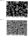
- the SEM image (7,500x magnification) of the product in Fig. 4 shows non-aggregated, microscale Si / C composite particles, which contain graphite and nano-Si particles inside
- the SEM image in Fig. 5 shows the carbon-coated surface of the particles.
- Elemental composition Si 20.6% by weight; C 75.0% by weight; O 3.5% by weight; N 2.5% by weight; B ⁇ 50 ppm; P ⁇ 50 ppm; Al ⁇ 25 ppm; Ca ⁇ 50 ppm; Cu ⁇ 10 ppm; K ⁇ 50 ppm; Li ⁇ 10 ppm; Zr 1100 ppm.
- Non-aggregated Si / C composite particles
- PAN polyacrylonitrile
- DMF dimethylformamide
- Super P conductive carbon black
- the resulting dispersion was sprayed with a laboratory spray dryer type B-290 (BÜCHI GmbH) with inert loop B-295 and dehumidifier B-296 (BÜCHI GmbH) and dried (nozzle tip 0.7 mm; nozzle cap 1.4 mm; nozzle temperature 130 ° C ; N 2 gas flow ⁇ 30; aspirator 100%; pump 20%). 13.8 g of a brown-black powder were obtained (84% yield).
- the SEM image (7,500x magnification) in Fig. 6 shows non-aggregated, microscale precomposite particles that are completely covered with oxygen-free polymer.
- the corresponding cross section in Fig. 7 (7,500x magnification) shows the even distribution of the components within the precomposite particle.
- the SEM image (1,500 times magnification) of the product in Fig. 8 shows non-aggregated, microscale Si / C composite particles that contain graphite and nano-Si particles inside.
- Fig. 9 shows the even distribution of the components and complete coating with carbon in cross section (1,500 times magnification).
- Elemental composition Si 24.4% by weight; C 65.6% by weight; O 4.62% by weight; N 2.67% by weight; B ⁇ 50 ppm; P ⁇ 50 ppm; Al ⁇ 25 ppm; Ca ⁇ 50 ppm; Cu ⁇ 10 ppm; K ⁇ 50 ppm; Li ⁇ 10 ppm; Zr 800 ppm.
- the electrochemical determination of the initial Coulomb efficiency was carried out on a half cell without reference.
- the electrode coating was used as the working electrode and lithium foil (Rockwood Lithium, thickness 0.5 mm) was used as the counter electrode.
- the electrolyte used consisted of a 1 molar solution of lithium hexafluorophosphate in a 3: 7 (v / v) mixture of ethylene carbonate and diethyl carbonate, which was mixed with 2% by weight of vinylene carbonate.
- the cell was built in a glove box ( ⁇ 1 ppm H 2 O, O 2 ), the water content in the dry matter of all components used was below 20 ppm.
- the electrochemical measurement was carried out at 20 ° C.
- the electrode was loaded or lithiated using the cc / cv method (constant current / constant voltage) with constant current of 33 mA / g (corresponds to C / 25) and after reaching the voltage limit of 5 mV with constant voltage until the current falls below 20 mA / g.
- the cell was discharged using the cc method (constant current) with constant current of 33 mA / g (corresponds to C / 25) until the voltage limit of 1.5 V is reached.
- the specific current selected was based on the weight of the coating.
- the initial Coulomb efficiency of the Si / C composite particle was 84.6 ⁇ 0.6% (mean value from triple measurement) and is therefore significantly higher than in Comparative Example 7.
- Non-aggregated Si / C composite particles
- PAN polyacrylonitrile
- DMF dimethylformamide
- the resulting dispersion was sprayed with a laboratory spray dryer type B-290 (BÜCHI GmbH) with inert loop B-295 and dehumidifier B-296 (BÜCHI GmbH) and dried (nozzle tip 0.7 mm; nozzle cap 1.4 mm; nozzle temperature 130 ° C ; N 2 gas flow ⁇ 30; aspirator 100%; pump 20%). 21.4 g of a brown-black powder were obtained (88% yield).
- the SEM image (1,500 times magnification) of the product in Fig. 10 shows non-aggregated, microscale Si / C composite particles that contain graphite and nano-Si particles inside.
- Fig. 11 shows the complete coating of the particles with carbon (30,000 times magnification).
- Elemental composition Si 19.6% by weight; C 72.2% by weight; O 5.5% by weight; N 2.4% by weight; B ⁇ 50 ppm; P 70 ppm; Al 2300 ppm; Ca 945 ppm; Cu 15 ppm; K 323 ppm; Li ⁇ 10 ppm; Zr 1100 ppm.
- the resulting dispersion was sprayed with a laboratory spray dryer type B-290 (BÜCHI GmbH) with inert loop B-295 and dehumidifier B-296 (BÜCHI GmbH) and dried (nozzle tip 0.7 mm; nozzle cap 1.5 mm; nozzle temperature 100 ° C ; N 2 gas flow ⁇ 30; aspirator 100%; pump 20%). 26.9 g of a brown-black powder were obtained (66% yield).
- the electrochemical determination of the initial Coulomb efficiency was carried out on a half cell without reference.
- the electrode coating was used as the working electrode and lithium foil (Rockwood Lithium, thickness 0.5 mm) was used as the counter electrode.
- the electrolyte used consisted of a 1 molar solution of lithium hexafluorophosphate in a 3: 7 (v / v) mixture of ethylene carbonate and diethyl carbonate, which was mixed with 2% by weight of vinylene carbonate.
- the cell was built in a glove box ( ⁇ 1 ppm H 2 O, O 2 ), the water content in the dry matter of all components used was below 20 ppm.
- the electrochemical measurement was carried out at 20 ° C.
- the electrode was charged or lithiated using the cc / cv method (constant current / constant voltage) with a constant current of 27 mA / g (corresponds to C / 25) and after reaching the voltage limit of 5 mV with constant voltage until the current falls below 20 mA / g.
- the cell was discharged in the cc process (constant current) with constant current of 27 mA / g (corresponds to C / 25) until the voltage limit of 1.5 V is reached.
- the selected specific current was based on the weight of the coating.
- the initial Coulomb efficiency of the Si / C composite particles from comparative example 7 was 79.7 ⁇ 0.1% (mean value from triple measurement) and is therefore significantly lower than in example 5.
Landscapes
- Chemical & Material Sciences (AREA)
- Chemical Kinetics & Catalysis (AREA)
- Electrochemistry (AREA)
- General Chemical & Material Sciences (AREA)
- Engineering & Computer Science (AREA)
- Composite Materials (AREA)
- Materials Engineering (AREA)
- Manufacturing & Machinery (AREA)
- Inorganic Chemistry (AREA)
- Battery Electrode And Active Subsutance (AREA)
- Silicon Compounds (AREA)
Description
- Die Erfindung betrifft ein Verfahren zur Herstellung von Präkompositpartikeln mittels Sprühtrocknung von Polymeren und Siliciumpartikel enthaltenden Zusammensetzungen, so erhältliche Präkompositpartikel, ein Verfahren zur Herstellung von Si/C-Kompositpartikeln durch thermische Behandlung der Präkompositpartikel, so erhältliche Si/C-Kompositpartikel und deren Verwendung in Elektrodenmaterialien für Lithiumionen-Batterien, insbesondere zur Herstellung der negativen Elektroden von Lithiumionen-Batterien.
- Wiederaufladbare Lithium-Ionen-Batterien sind momentan die kommerziell verfügbaren elektrochemischen Energiespeicher mit den höchsten Energiedichten von bis zu 250 Wh/kg. Sie werden vor allem im Bereich der tragbaren Elektronik, für Werkzeuge und auch für Transportmittel, wie beispielsweise Fahrräder oder Automobile, genutzt. Insbesondere für die Anwendung in Automobilen ist es jedoch notwendig, die Energiedichte der Batterien weiter deutlich zu steigern, um höhere Reichweiten der Fahrzeuge zu erreichen.
- Als negatives Elektrodenmaterial ("Anode") wird in der Praxis gegenwärtig vor allem graphitischer Kohlenstoff verwendet. Graphitischer Kohlenstoff zeichnet sich durch seine stabilen Zykleneigenschaften und seine, im Vergleich zu Lithiummetall, das in Lithium-Primärzellen verwendet wird, recht hohe Handhabungssicherheit aus. So erfährt graphitischer Kohlenstoff bei der Ein- und Auslagerung von Lithium nur geringe Volumenänderungen, beispielsweise im Bereich von 10% für die Grenzstöchiometrie von LiC6. Nachteilig ist jedoch seine relativ niedrige elektrochemische Kapazität von theoretisch 372 mAh/g, die nur etwa ein Zehntel der mit Lithiummetall theoretisch erreichbaren elektrochemischen Kapazität entspricht.
- Dagegen besitzt Silicium mit 4199 mAh/g die höchste bekannte Speicherkapazität für Lithium-Ionen. Nachteiligerweise erleiden Silicium enthaltende Elektrodenaktivmaterialien beim Laden bzw.
- Entladen mit Lithium extreme Volumenänderungen von bis ca. 300%. Durch diese Volumenänderung kommt es zu einer starken mechanischen Beanspruchung des Aktivmaterials und der gesamten Elektrodenstruktur, die durch elektrochemisches Mahlen zu einem Verlust der elektrischen Kontaktierung und damit zur Zerstörung der Elektrode unter Kapazitätsverlust führt. Weiterhin reagiert die Oberfläche des eingesetzten Silicium-Anodenmaterials mit Bestandteilen des Elektrolyten unter kontinuierlicher Bildung passivierender Schutzschichten (Solid Electrolyte Interface; SEI), was zu einem irreversiblen Verlust an mobilem Lithium führt.
- Um die Probleme im Zusammenhang mit der starken Volumenausdehnung des Aktivmaterials und der SEI-Bildung in Si-haltigen Anoden zu lösen, wurden in den letzten Jahren verschiedene Ansätze zur elektrochemischen Stabilisierung Si-haltiger Elektrodenaktivmaterialien verfolgt, wie beispielsweise beschrieben von A. J. Appleby in J. Power Sources 2007, 163, Seiten 1003 bis 1039. Vielfach wird Silicium-haltiges Aktivmaterial in Kombination mit Kohlenstoff eingesetzt. In einem Ansatz wird das Si-haltige Aktivmaterial in Form einer physikalischen Mischung mit Graphit in die Elektrodenbeschichtung einzusetzen, wie in
EP 1730800 B1 gelehrt. In einem anderen Ansatz werden die beiden Elemente Silicium und Kohlenstoff strukturell zu einem Komposit-Material verbunden, wie in einem Übersichtsartikel von M. Rossi in J. Power Sources 2014, 246, Seiten 167 bis 177 zusammengefasst. - Ein gängiges Verfahren zur Herstellung von sphärischen, mikroskaligen Kohlenstoff-Partikeln ist die Sprühtrocknung. Hierbei werden Lösungen oder Dispersionen von Kohlenstoff-Precursoren (C-Precursor), wie Zucker, Lignin, Polyvinylalkohole, Polyalkylenoxide oder Resorcin-Formaldehyd-Harz, zu Tröpfchen versprüht und anschließend getrocknet unter Bildung von Partikeln, deren Partikelgröße und Partikelform der Tropfenform und Tropfengröße der versprühten Tröpfchen entspricht. Die so erhaltenen getrockneten, sphärischen C-Precursorpartikel können durch anschließende Carbonisierung in Partikel aus amorphem Kohlenstoff überführt werden. So beschreiben die
JP1301717 JP64043531 WO-A 08069633 CN 102723469 ist die Sprühtrocknung von Mischungen enthaltend Polymerharz, beispielsweise Phenolharz, und Graphit bekannt. - In weiteren Ansätzen werden zur Sprühtrocknung Dispersionen eingesetzt, die neben C-Precursoren zusätzlich Silicium-Nanopartikel enthalten. Carbonisierung so erhaltener PräkompositPartikel führt zu Si/C-Kompositpartikeln, wie beispielsweise beschrieben in
US2011165468 oder von B. Li in Electrochem. Comm. 2014, 49, Seiten 98 bis 102. F. Beguin beschreibt in Electrochimica Acta 2015, 174, Seiten 361 bis 368 entsprechende Verfahren mit Polyvinylalkohol als C-Precursor. H. Cui beschreibt in Ceramics Int. 2015 (im Druck) die Herstellung von porösen Si/C-Kompositen, indem SiO2-beschichtete nano-SiliciumPartikel zusammen mit Phenolharz versprüht und anschließend zu Si/C-Kompositpartikeln carbonisiert werden. Abschließend wird die SiO2-Beschichtung mit Flusssäure herausgeätzt. - Schließlich sind auch Ansätze bekannt, in denen zur Sprühtrocknung Dispersionen eingesetzt werden, die Kohlenstoff-haltige Additive, sauerstoffreiche C-Precursoren und nano-Silicium enthalten. Anschließende Carbonisierung ergibt dann Si/C-Kompositpartikel. So beschreibt F. Su (J. Mater Chem. A, 2015, 3, Seiten 5859 bis 5865) die Sprühtrocknung von graphitisiertem Nadelkoks zusammen mit Nano-Silicium und Saccharose und anschließendes Carbonisieren. F. Su (RSC Adv. 2014, 4, Seiten 43114 bis 43120) beschreibt einen analogen Ansatz unter Einsatz von Leitruß, nano-Silicium und Saccharose. Y. Yang (Electrochimica Acta 2015, 178, Seiten 65 bis 73) setzt hierfür Carbon-Nanotubes, Nano-Silicium und Phenolformaldehydharz ein. X. Hou (J. Power Sources 2014, 248, Seiten 721 bis 728) beschreibt ein zweistufiges Verfahren zur Herstellung von Si/C-Kompositen, in dem zuerst nano-Silicium zusammen mit Graphit und als C-Precursor Citronensäure sprühgetrocknet werden. Die Trocknungsprodukte wurden nach Temperaturbehandlung mit Pech beschichtet, anschließend einer Sprühtrocknung und schließlich einer Pyrolyse unterworfen.
- Es bereitet jedoch weiterhin Probleme, mittels Sprühtrocknung von Polymeren und Siliciumpartikeln enthaltenden Dispersionen Partikel herzustellen, die nach Pyrolyse zu geeigneten Si/C-Kompositpartikeln für Elektrodenmaterialien von Lithiumionen-Batterien führen und insbesondere die hierfür gewünschten Teilchengrößen sowie möglichst enge Teilchengrößenverteilungen aufweisen. Gewünscht ist insbesondere, die in Dispersion vorliegenden Primärpartikel durch Sprühtrocknung in entsprechende partikuläre Feststoffe sowie anschließend durch Carbonisieren in entsprechende Si/C-Kompositpartikel zu überführen, ohne dass es im Zuge der Sprühtrocknung oder der Carbonisierung zu einer Partikelaggregation, d.h. einem Zusammenwachsen unterschiedlicher Primärpartikel kommt. Dementsprechend soll nach Möglichkeit jedes beim Versprühen entstehende Tröpfchen beim Trocknen in ein separates Partikel überführt werden. Bei herkömmlichen Sprühtrocknungsverfahren tritt eine Aggregation von Primärpartikeln in erheblichem Maße auf, was zu getrockneten Partikeln mit entsprechend großen Durchmessern und breiten Teilchengrößenverteilungen führt. Werden herkömmliche Sprühtrocknungsprodukte carbonisiert, so kann hierbei eine Versinterung von Partikeln auftreten, so dass auch in diesem Schritt eine unerwünschte Partikelaggregation erfolgen kann, wodurch große Partikel mit üblicherweise breiten Teilchengrößenverteilungen gebildet werden. Partikel mit unerwünschter Größe, d.h. störendes Über- oder Unterkorn, können zwar durch Sieben oder Sichten abgetrennt werden. Ein solcher zusätzlicher Arbeitsschritt ist aber aufwändig und führt zudem zu Abfallmaterial. Si/C-Kompositpartikel mit großen Durchmessern können bei Einsatz in Lithiumionen-Batterien fatal sein, da solche Partikel die Schichtdicke von Anodenmaterial in den Batterien überschreiten können und damit die Elektrode oder den Separator der Batterie durchstoßen können, was zu einem Kurzschluss der Batterie führt und damit die Funktionsfähigkeit der Batterie terminiert. Diese Problematik ist umso gravierender, als das in den Partikeln enthaltene Silicium während der Ladezyklen extreme Volumenausdehnungen erfährt, so dass sich das Volumen großer Partikel extrem vergrößert. Insgesamt sind sämtliche Probleme im Zusammenhang mit dem sogenannten elektrochemischen Mahlen durch Si/C-Kompositpartikel mit größeren Partikeln ausgeprägter.
- Vor diesem Hintergrund bestand die Aufgabe, nicht-aggregierte oder möglichst wenig aggregierte Präkompositpartikel bereitzustellen, mit denen durch thermische Behandlung bzw. Carbonisieren nicht-aggregierte oder möglichst wenig aggregierte Si-/C-Kompositpartikel zugänglich werden. Aufwändiges Abtrennen von Über- oder Unterkorn sollte möglichst vermieden werden.
- Überraschenderweise wurde diese Aufgabe gelöst, indem Mischungen umfassend Sauerstoff-freie Polymere, Kohlenstoff enthaltende Additive und Siliciumpartikel sprühgetrocknet und die so erhaltenen Präkompositpartikel durch anschließende thermische Behandlung in Si/C-Kompositpartikel überführt wurden. Durch die erfindungsgemäße Merkmalskombination wurden Si/C-Kompositpartikel mit den für Lithiumionen-Batterien gewünschten Partikeldurchmessern und Partikelgrößenverteilungen zugänglich. Unerwarteter Weise können mit den erfindungsgemäßen Si/C-Kompositpartikeln Lithiumionen-Batterien mit höherer Coulomb-Effizienz oder einem geringeren initialen, irreversiblen Verlust an mobilem Lithium im ersten Lade-/Entladezyklus der Batterien erhalten werden.
- Ein Gegenstand der Erfindung ist ein Verfahren zur Herstellung von Präkompositpartikeln, dadurch gekennzeichnet, dass Mischungen enthaltend Siliciumpartikel, ein oder mehrere Sauerstoff-freie Polymere, ein oder mehrere Kohlenstoff-Additive (C-Additive) basierend auf einer Kohlenstoffmodifikation und ein oder mehrere Dispergierflüssigkeiten mittels Sprühtrocknung getrocknet werden.
- Ein weiterer Gegenstand der Erfindung sind die nach dem vorgenannten Verfahren erhältlichen Verfahrensprodukte (Präkompositpartikel).
- Ein Präkompositpartikel ist allgemein ein Agglomerat von Siliciumpartikeln, C-Additiven und Sauerstoff-freien Polymeren. In Folge ihrer erfindungsgemäßen Herstellung sind die Siliciumpartikel und die C-Additive in den Präkompositpartikeln im Allgemeinen ganz oder teilweise von den Sauerstoff-freien Polymeren umhüllt. Die Oberfläche der Präkompositpartikel wird vorzugsweise ganz oder teilweise, besonders bevorzugt im Wesentlichen durch die Sauerstoff-freien Polymere gebildet. In Anbetracht dieser Strukturmerkmale war es umso überraschender, dass die erfindungsgemäßen Präkompositpartikel die erfindungsgemäße Aufgabe lösten - zumal die Sauerstoff-freien Polymere auch Bindemitteleigenschaften haben. Durch bloßes physikalisches Mischen von Siliciumpartikeln, Sauerstoff-freien Polymeren und C-Additiven oder durch nicht-erfindungsgemäßes Trocknen der erfindungsgemäßen Mischungen sind Präkompositpartikel mit erfindungsgemäßer Struktur, insbesondere mit der erfindungsgemäß erhaltenen Verteilung von Sauerstoff-freien Polymeren in den Präkompositpartikeln dagegen nicht erhältlich.
- Die Sauerstoff-freien Polymere beinhalten in ihrer chemischen Summenformel allgemein keinen Sauerstoff. Sauerstoff-freie Polymere können beispielsweise vernetzte, verzweigte und insbesondere lineare Polymere sein, die keine Sauerstoff-haltigen funktionellen Gruppen tragen, wie Alkoxy- (z.B. Ether, Acetale), Hydroxy- (Alkohole), Oxo- (Ketone), Formyl- (Aldehyde), Carboxy- (Carbonsäuren), Metallcarboxylato- (Carbonsäuresalze), Alkyloxycarbonyl- (Ester), Halogenformyl- (Carbonsäurehalogenide), Carbamoyl- (Carbonsäureamide), Carbamat- (Urethane), Sulfonato- (Sulfonsäure), Metallsulfonato- (Sulfonsäuresalze), Anhydrid- oder Siloxan-Gruppen.
- Beispiele für Sauerstoff-freie Polymere sind Polyacrylnitril; Polyolefine, wie Polyethylen, Ethylen-Propylen-Dien-Terpolymere; Polyvinylhalogenide, wie Polyvinylchlorid, Polyvinylidenchlorid, Polyvinylidenfluorid oder Polytetrafluorethylen; Polyvinylaromaten oder Polyaromaten, wie Polyanilin, Polystyrol, Polybenzimidazol, Polypyrrol, Poly-para-phenylen; polyaromatische Kohlenwasserstoffe, wie Peche oder Teere, insbesondere Mesogenes Pech, Mesophasen-Pech, Petrolpech, Steinkohlenteerpech. Bevorzugte Sauerstoff-freie Polymere sind Polyacrylnitril, Polyanilin und Polystyrol. Besonders bevorzugt ist Polyacrylnitril.
- Die Sauerstoff-freien Polymere lassen sich allgemein durch thermische Behandlung in leitfähige Kohlenstoff-Strukturen überführen.
- Die Präkompositpartikel basieren vorzugsweise zu ≤ 95 Gew.%, besonders bevorzugt ≤ 90 Gew.% und am meisten bevorzugt ≤ 85 Gew.% auf Sauerstoff-freien Polymeren. Die Präkompositpartikel basieren vorzugsweise zu ≥ 5 Gew.%, besonders bevorzugt ≥ 10 Gew.% und am meisten bevorzugt ≥ 15 Gew.% auf Sauerstoff-freien Polymeren. Die vorgenannten Angaben in Gew.% beziehen sich jeweils auf das Trockengewicht der Präkompositpartikel.
- Bevorzugte C-Additive werden ausgewählt aus der Gruppe umfassend Graphit, (Leit-)Ruß, Aktivkohle, amorphen Kohlenstoff, pyrolytischen Kohlenstoff, Soft-Carbon, Hard-Carbon, Carbon Nanotubes (CNTs), Fullerene und Graphen. Besonders bevorzugte C-Additive sind Graphit, Leitruß und Aktivkohle.
- Die Präkompositpartikel basieren vorzugsweise zu ≤ 90 Gew.%, besonders bevorzugt ≤ 85 Gew.% und am meisten bevorzugt ≤ 80 Gew.% auf C-Additiven. Die Präkompositpartikel basieren vorzugsweise zu ≥ 3 Gew.%, besonders bevorzugt ≥ 5 Gew.% und am meisten bevorzugt ≥ 7 Gew.% auf C-Additiven. Die vorgenannten Angaben in Gew.% beziehen sich jeweils auf das Trockengewicht der Präkompositpartikel.
- Siliciumpartikel können aus elementarem Silicium, einem Siliciumoxid oder einer binären, ternären oder multinären Silicium/Metall-Legierung (mit beispielsweise Li, Na, K, Sn, Ca, Co, Ni, Cu, Cr, Ti, Al, Fe) bestehen. Bevorzugt wird elementares Silicium eingesetzt, insbesondere da dieses eine vorteilhaft hohe Speicherkapazität für Lithium-Ionen aufweist.
- Unter elementarem Silicium ist im Allgemeinen hochreines Polysilicium, mit geringem Anteil an Fremdatomen (wie beispielsweise B, P, As), gezielt mit Fremdatomen dotiertes Silicium (wie beispielsweise B, P, As), aber auch Silicium aus metallurgischer Verarbeitung, welches elementare Verunreinigung (wie beispielsweise Fe, Al, Ca, Cu, Zr, C) aufweisen kann, zu verstehen.
- Falls die Siliciumpartikel ein Siliciumoxid enthalten, dann liegt die Stöchiometrie des Oxids SiOx bevorzugt im Bereich 0 < x < 1,3. Falls die Siliciumpartikel ein Siliciumoxid mit höherer Stöchiometrie enthalten, dann ist dessen Schichtdicke auf der Oberfläche bevorzugt kleiner als 10 nm.
- Wenn die Siliciumpartikel mit einem Alkalimetall M legiert sind, dann liegt die Stöchiometrie der Legierung MySi bevorzugt im Bereich 0 < y < 5. Die Siliciumpartikel können gegebenenfalls prälithiiert sein. Für den Fall, dass die Siliciumpartikel mit Lithium legiert sind, liegt die Stöchiometrie der Legierung LizSi bevorzugt im Bereich 0 < z < 2,2.
- Besonders bevorzugt sind Siliciumpartikel, die ≥ 80 Mol% Silicium und/oder ≤ 20 Mol% Fremdatome, ganz besonders bevorzugt ≤ 10 Mol% Fremdatome enthalten.
- Die Oberfläche der Siliciumpartikel kann gegebenenfalls durch eine Oxidschicht oder durch andere anorganische und organische Gruppen abgedeckt sein. Besonders bevorzugte Siliciumpartikel tragen auf der Oberfläche Si-OH- oder Si-H-Gruppen oder kovalent angebundene organische Gruppen, wie beispielsweise Alkohole oder Alkene. Durch die organischen Gruppen kann beispielsweise die Oberflächenspannung der Siliciumpartikel gesteuert werden. Diese kann so an die Lösemittel oder Bindemittel angepasst werden, die bei der Herstellung der Granulate oder bei der Herstellung der Elektrodenbeschichtungen eingesetzt werden.
- Die Siliciumpartikel weisen vor der Sprühtrocknung volumengewichtete Partikelgrößenverteilungen mit Medianwerten des Durchmessers d50 von vorzugsweise 50 nm bis 50 µm, besonders bevorzugt 100 nm bis 30 µm und am meisten bevorzugt 150 nm bis 20 µm auf.
- Die volumengewichtete Partikelgrößenverteilung ist bestimmbar durch statische Laserstreuung unter Anwendung des Fraunhofer- oder des Mie-Modells mit dem Messgerät Horiba LA 950 mit Ethanol oder Isopropanol als Dispergiermedium für die Siliciumpartikel.
- Die Siliciumpartikel sind vorzugsweise nicht agglomeriert, insbesondere nicht aggregiert.
- Aggregiert bedeutet, dass sphärische oder weitestgehend sphärische Primärpartikel, wie sie beispielsweise zunächst in Gasphasenprozessen zur Herstellung von Siliciumpartikeln gebildet werden, im weiteren Reaktionsverlauf des Gasphasenprozesses zusammenwachsen und auf dies Weise Aggregate bilden. Diese Aggregate können im weiteren Reaktionsverlauf Agglomerate bilden. Agglomerate sind eine Zusammenballung von Primärpartikeln oder Aggregaten ohne kovalente chemische Bindungen. Agglomerate können in manchen Fällen mit Knet- und Dispergierverfahren wieder in die Aggregate aufgespalten werden, häufig ist dieses jedoch nicht möglich. Aggregate lassen sich mit diesen Verfahren nicht oder nur teilweise in die Primärpartikel zerlegen. Das Vorliegen von Siliciumpartikeln in Form von Aggregaten oder Agglomeraten kann beispielsweise mittels herkömmlicher Raster-Elektronen-Mikroskopie (REM) sichtbar gemacht werden. Statische Lichtstreuungsmethoden zur Bestimmung der Teilchengrößenverteilungen können dagegen nicht zwischen Aggregaten oder Agglomeraten unterscheiden.
- Die Siliciumpartikel haben eine Sphärizität von vorzugsweise 0,3 ≤ ψ ≤ 1, besonders bevorzugt 0,4 ≤ ψ ≤ 1 und am meisten bevorzugt 0,5 ≤ ψ ≤ 1. Die Sphärizität ψ ist das Verhältnis aus der Oberfläche einer Kugel gleichen Volumens zur tatsächlichen Oberfläche eines Körpers (Definition von Wadell). Sphärizitäten können beispielsweise aus herkömmlichen REM-Aufnahmen ermittelt werden.
- Die Siliciumpartikel haben vorzugsweise bestimmte Schüttguteigenschaften. Schüttguteigenschaften sind beispielsweise in der internationalen Norm FEM 2.581 der "Federation Europeenne de la Manutention" beschrieben. In der Norm FEM 2.582 werden die allgemeinen und spezifischen Schüttguteigenschaften hinsichtlich der Klassifizierung definiert. Kennwerte, die die Konsistenz und den Zustand des Gutes beschreiben sind zum Beispiel Kornform und Korngrößenverteilung (FEM 2.581 / FEM 2.582: General characteristics of bulk products with regard to their classification and their symbolization).
- Nach DIN ISO 3435 können Schüttgüter in Abhängigkeit der Beschaffenheit der Kornkanten in sechs unterschiedliche Kornformen untergliedert werden:
- I: scharfe Kanten mit ungefähr gleichen Ausmaßen in den drei Dimensionen (Bsp.: Würfel);
- II: scharfe Kanten, deren eine deutlich länger ist als die anderen beiden (Bsp.: Prisma, Klinge);
- III: scharfe Kanten, deren eine deutlich kleiner ist als die beiden anderen (Bsp.: Platte, Schuppen);
- IV: runde Kanten mit ungefähr gleichen Ausmaßen in den drei Dimensionen (Bsp.: Kugel);
- V: runde Kanten, in einer Richtung deutlich größer als in den anderen beiden (Bsp.: Zylinder, Stange);
- VI: faserig, fadenförmig, lockenförmig, verschlungen.
- Die Siliciumpartikel haben vorzugsweise Kornformen I bis VI, mehr bevorzugt I, II, III oder IV und besonders bevorzugt I oder IV gemäß DIN ISO 3435.
- Die Präkompositpartikel basieren vorzugsweise zu ≤ 50 Gew.%, besonders bevorzugt ≤ 45 Gew.% und am meisten bevorzugt ≤ 40 Gew.% auf Siliciumpartikeln. Die Präkompositpartikel basieren vorzugsweise zu ≥ 2 Gew.%, besonders bevorzugt ≥ 5 Gew.% und am meisten bevorzugt ≥ 7 Gew.% auf Siliciumpartikeln. Die vorgenannten Angaben in Gew.% beziehen sich jeweils auf das Trockengewicht der Präkompositpartikel.
- Die Siliciumpartikel können beispielsweise mittels Gasphasenabscheidung oder vorzugsweise durch Mahlprozesse hergestellt werden.
- Als Mahlprozesse kommen Trocken- oder Nassmahlprozesse in Betracht. Hierbei werden vorzugsweise Strahlmühlen, wie Gegenstrahlmühlen, oder Prallmühlen, Planetenkugelmühlen oder Rührwerkskugelmühlen eingesetzt. Die Strahlmühlen weisen bevorzugt einen integrierten Windsichter auf, der statisch oder dynamisch ausgebildet sein kann, oder sie werden im Kreislauf mit einem externen Windsichter betrieben.
- Die Nassmahlung erfolgt im Allgemeinen in einer Suspension mit organischen oder anorganischen Dispergiermedien. Bevorzugte Dispergiermedien sind die weiter unten beschriebenen Dispergierflüssigkeiten.
- Bei der Nassmahlung werden vorzugsweise Mahlkörper verwendet, deren mittlerer Durchmesser 10 bis 1000 mal größer ist als der 90%-Perzentilwert d90 des Durchmessers des eingesetzten Mahlguts, bezogen auf die Partikelgrößenvolumenverteilung. Besonders bevorzugt sind Mahlkörper, deren mittlerer Durchmesser 20 bis 200-mal größer ist als der d90-Wert der Ausgangsverteilung des Mahlguts.
- Als Dispergierflüssigkeit können organische und/oder anorganische Lösungsmittel eingesetzt werden. Es können auch Mischungen aus zwei oder mehr Dispergierflüssigkeiten eingesetzt werden.
- Ein Beispiel für ein anorganisches Lösungsmittel ist Wasser.
- Organische Lösungsmittel sind beispielsweise Kohlenwasserstoffe, Ether, Ester, Stickstoff-funktionelle Lösungsmittel, Schwefel-funktionelle Lösungsmittel oder Alkohole. Die organischen Lösungsmittel enthalten vorzugsweise 1 bis 12 Kohlenstoffatome und besonders bevorzugt 1 bis 8 Kohlenstoffatome. Beispiele für Alkohole sind Methanol, Ethanol, Propanol, Butanol und Benzylalkohol. Kohlenwasserstoffe können beispielsweise aliphatisch oder aromatisch, substituiert oder unsubstituiert sein. Beispiele hierfür sind chlorierte Kohlenwasserstoffe, wie Dichlormethan, Trichlormethan, Tetrachlormethan, 1,2-Dichlorethan und Trichlorethylen; unsubstituierte Kohlenwasserstoffe, wie Pentan, n-Hexan, Hexan-Isomerengemische, Heptan, Oktan, Waschbenzin, Petrolether, Benzol, Toluol und Xylole. Beispiele für Ether sind Dioxan, Tetrahydrofuran, Diethylether, Di-isopropylether und Diethylenglycoldimethylether. Beispiele für Ester sind Ethylacetat, Butylacetat, Propylpropionat, Ethylbutyrat und Ethyl-isobutyrat. Beispiele für Stickstoff-funktionelle Lösungsmittel sind Nitrobenzol, Dimethylformamid, N-Methyl-2-Pyrrolidon und N-Ethyl-2-Pyrrolidon. Ein Beispiel für ein Schwefel-funktionelles Lösungsmittel ist Dimethylsulfoxid. Bevorzugte Lösungsmittel sind Ethanol und 2-Propanol, Dimethylformamid, N-Methyl-2-Pyrrolidon, N-Ethyl-2-Pyrrolidon, Dimethylsulfoxid oder Gemische dieser Lösungsmittel.
- Die Dispergierflüssigkeit liegt im Allgemeinen bei Raumtemperatur in flüssiger Form vor und hat bei 20°C eine Viskosität von vorzugsweise ≤ 100 mPas und besonders bevorzugt ≤ 10 mPas. Die Dispergierflüssigkeit ist bevorzugt inert oder schwach reaktiv gegenüber Silicium.
- Die Mischungen, die zur Sprühtrocknung eingesetzt werden, enthalten vorzugsweise ≥ 5 Gew.%, besonders bevorzugt ≥ 10 Gew.% und am meisten bevorzugt ≥ 20 Gew.% an Dispergierflüssigkeit. Die Mischungen enthalten vorzugsweise ≤ 99 Gew.%, besonders bevorzugt ≤ 98,5 Gew.% und am meisten bevorzugt ≤ 98 Gew.% an Dispergierflüssigkeit. Die vorgenannten Angaben in Gew.% beziehen sich jeweils auf das Trockengewicht der Mischungen, die zur Sprühtrocknung eingesetzt werden.
- Die Mischungen können ein oder mehrere Zusatzstoffe enthalten. Beispiele hierfür sind inaktive Materialien auf Basis von Metallen (wie Kupfer, Zirkonium), Oxiden, Carbiden oder Nitriden.
- Die Präkompositpartikel basieren vorzugsweise zu 0 bis 30 Gew.%, besonders bevorzugt 1 bis 25 Gew.% und am meisten bevorzugt 2 bis 20 Gew.% auf Zusatzstoffen, bezogen auf das Trockengewicht der Präkompositpartikel. In einer bevorzugten, alternativen Ausführungsform enthalten die Präkompositpartikel keine Zusatzstoffe.
- Die Mischungen können auch ein oder mehrere Additive enthalten, wie beispielsweise Porenbildner, Verlaufsmittel, Dotiermittel oder Stoffe, die die elektrochemische Stabilität der Elektrode in der Batterie verbessern. Bevorzugte Additive sind Porenbildner. Es können gängige Porenbildner eingesetzt werden.
- Die Präkompositpartikel basieren vorzugsweise zu 0 bis 50 Gew.%, besonders bevorzugt 1 bis 40 Gew.% und am meisten bevorzugt 2 bis 30 Gew.% auf Additiven, bezogen auf das Trockengewicht der Präkompositpartikel. In einer bevorzugten, alternativen Ausführungsform enthalten die Präkompositpartikel keine Additive.
- Die Präkompositpartikel fallen vorzugsweise in Form von isolierten Partikeln oder lockeren Agglomeraten von Präkompositpartikeln an, jedoch im Allgemeinen nicht in Form von Aggregaten von Präkompositpartikeln. Etwaige Agglomerate von Präkompositpartikeln lassen sich in die einzelnen Präkompositpartikel separieren, beispielsweise mit Knet- oder Dispergierverfahren. Aggregate von Präkompositpartikeln lassen sich auf diese Weise nicht in die einzelnen Partikel trennen, ohne Präkompositpartikel zu zerstören.
- Die Präkompositpartikel sind bevorzugt sphärisch, können aber auch eine Splitterform aufweisen oder in Form von hohlen Sphären vorliegen, wobei massive sphärische Partikel besonders bevorzugt sind.
- Die Präkompositpartikel haben eine Sphärizität von vorzugsweise 0,3 ≤ ψ ≤ 1, besonders bevorzugt 0,5 ≤ ψ ≤ 1 und am meisten bevorzugt 0,8 ≤ ψ ≤ 1. Die Sphärizität ψ ist das Verhältnis aus der Oberfläche einer Kugel gleichen Volumens zur tatsächlichen Oberfläche eines Körpers (Definition von Wadell). Sphärizitäten können beispielsweise aus herkömmlichen REM-Aufnahmen ermittelt werden.
- Die volumengewichtete Partikelgrößenverteilung mit Durchmesser-Perzentilen d50 der Präkompositpartikel ist vorzugsweise ≤ 100 µm, besonders bevorzugt ≤ 50 µm und am meisten bevorzugt ≤ 20 µm, aber vorzugsweise ≥ 1 µm.
- Die Partikelgrößenverteilung der Präkompositpartikel kann bimodal oder polymodal sein und ist bevorzugt monomodal, besonders bevorzugt schmal. Die volumengewichtete Partikelgrößenverteilung der Präkompositpartikel hat eine Breite (d90-d10)/d50 von bevorzugt ≤ 1,5, besonders bevorzugt ≤ 1 und am meisten bevorzugt ≤ 0,9.
- Die Bestimmung der volumengewichteten Partikelgrößenverteilung der Präkompositpartikel erfolgte durch statische Laserstreuung unter Anwendung des Mie-Modells mit dem Messgerät Horiba LA 950 mit Ethanol als Dispergiermedium für die Präkompositpartikel.
- Die Präkompositpartikel weisen typischerweise BET-Oberflächen auf von bevorzugt 1 bis 300 m2/g, besonders bevorzugt 2 bis 250 m2/g und am meisten bevorzugt 5 bis 200 m2/g (Bestimmung nach DIN ISO 9277:2003-05).
- Die Mischungen, die zur Sprühtrocknung eingesetzt werden, können durch beliebiges Mischen ihrer einzelnen Bestandteile hergestellt werden. Das Mischen ist an keine besondere Vorgehensweise gebunden. Die Sauerstoff-freien Polymere, die C-Additive und die Siliciumpartikel können gemeinsam oder nacheinander mit Dispergierflüssigkeit gemischt werden. Vorzugsweise werden zunächst Sauerstoff-freie Polymere mit Dispergierflüssigkeit gemischt und anschließend werden gemeinsam oder separat, gleichzeitig oder nacheinander C-Additive und Siliciumpartikel zugegeben.
- Die Sauerstoff-freien Polymere sind in den Dispergierflüssigkeiten vorzugsweise gelöst. Vorzugsweise lassen sich bei 20°C in 100 mL Dispergierflüssigkeit mindestens 1 g Sauerstoff-freie Polymere lösen. Die Siliciumpartikel und die C-Additive sind üblicherweise in den Dispergierflüssigkeiten dispergiert.
- Das Mischen kann in gängigen Mischvorrichtungen durchgeführt werden, wie beispielsweise in Rotor-Stator-Maschinen, Hochenergiemühlen, Planetenmischer, Kneter, Magnetrührer, Rührwerkskugelmühlen, Rüttelplatten, Dissolvern, Ultraturrax, Rollbänken oder Ultraschallgeräten. Ultraschall kann auch Anwendung finden.
- Die Sprühtrocknung kann in hierfür gängigen Anlagen und unter an sich gängigen Bedingungen durchgeführt werden. Die Zerstäubung in Sprühtrocknungsanlagen kann beispielsweise mittels Ein-, Zwei- oder Mehrstoffdüsen oder mit einer rotierenden Scheibe erfolgen. Die Eintrittstemperatur der zu trocknenden Mischung in die Sprühtrocknungsanlage ist vorzugsweise größer oder gleich der Siedetemperatur der zu trocknenden Mischung und besonders bevorzugt um ≥ 10°C höher als die Siedetemperatur der zu trocknenden Mischung. Beispielsweise beträgt die Eintrittstemperatur vorzugsweise 80°C bis 220°C, besonders bevorzugt 100°C bis 180°C. Die Austrittstemperatur ist vorzugsweise ≥ 30°C, besonders bevorzugt ≥ 40°C und am meisten bevorzugt ≥ 50°C. Im Allgemeinen liegt die Austrittstemperatur im Bereich von 30°C bis 100°C, bevorzugt von 45°C bis 90°C. Der Druck in der Sprühtrocknungsanlage ist bevorzugt der Umgebungsdruck.
- Die Trocknung kann in Umgebungsluft, synthetischer Luft oder vorzugsweise in einer Inertgasatmosphäre, beispielsweise in Stickstoff- oder Argon-Atmosphäre erfolgen. Insbesondere bei Verwendung organischer Lösungsmittel als Dispergierflüssigkeit ist der Einsatz von Inertgas bevorzugt.
- In der Sprühtrocknungsanlage haben die versprühten Mischungen Primärtröpfchengrößen von vorzugsweise 1 bis 100 µm, besonders bevorzugt 2 bis 50 µm und am meisten bevorzugt 5 bis 20 µm.
- Über die Einstellungen der Inlet-Temperatur, des Gasflusses (Flow), sowie der Pumprate (Feed), die Wahl der Düse, des Aspirators, die Wahl der Dispergierflüssigkeit oder auch der Feststoffkonzentration der Sprühdispersion lassen sich die Größe der Primärpartikel, Restfeuchte im Produkt und die Ausbeute des Produkts in an sich bekannter Weise einstellen. Beispielsweise werden bei höherer Feststoffkonzentration der Sprühsuspension Primärpartikel mit größeren Partikelgrößen erhalten. Auch der Gasfluss hat Einfluss auf die Partikelgröße. Für feine Partikel werden vorzugsweise hohe und für größere Partikel vorzugsweise niedrige Gasflüsse eingesetzt. Der Gasfluss beträgt vorzugsweise 84 bis 820 L/h, besonders bevorzugt 350 bis 600 L/h. Die Gasströme können über einen Aspirator umgewirbelt und somit im Kreis gefahren werden. Der Aspirator kann beispielsweise auf 0 bis 35 m3/h eingestellt werden, wobei eine Umwirbelung von 20 bis 35 m3/h bevorzugt ist.
- Die durch Sprühtrocknung erhaltenen Präkompositpartikel können auf unterschiedliche, gängige Weise aus dem Gasstrom abgetrennt werden, beispielsweise über Filter, Klassierungsverfahren, wie Sichten, oder bevorzugt Zyklone.
- Die Präkompositpartikel können zur Entfernung von Restfeuchte gegebenenfalls weiter getrocknet oder direkt weiterverwertet werden.
- Ein weiterer Gegenstand der Erfindung ist ein Verfahren zur Herstellung von Si/C-Kompositpartikeln, dadurch gekennzeichnet, dass
Mischungen enthaltend Siliciumpartikel, ein oder mehrere Sauerstoff-freie Polymere, ein oder mehrere C-Additive basierend auf einer Kohlenstoffmodifikation und ein oder mehrere Dispergierflüssigkeiten mittels Sprühtrocknung getrocknet werden und die so erhaltenen Präkompositpartikel thermisch behandelt werden. - Ein weiterer Gegenstand der Erfindung sind die nach dem vorgenannten Verfahren erhältlichen Si/C-Kompositpartikel.
- Durch die thermische Behandlung werden die Präkompositpartikel in Si/C-Kompositpartikel überführt. Durch die thermische Behandlung der Präkomposite erfolgt im Allgemeinen eine Carbonisierung der Sauerstoff-freien Polymere. Die Sauerstoff-freien Polymere werden dabei vorzugsweise in anorganischen Kohlenstoff überführt. Die Kohlenstoffausbeuten beim Carbonisieren der Sauerstoff-freien Polymere betragen vorzugsweise ≥ 15%, besonders bevorzugt ≥ 20% und am meisten bevorzugt ≥ 25%, bezogen auf das Gesamtgewicht der Sauerstoff-freien Polymere. Der Kohlenstoff in den Si/C-Kompositpartikeln kann kristallin oder amorph vorliegen sowie Mischungen aus kristallinen und amorphen Bestandteilen enthalten.
- Auf Grund der erfindungsgemäßen Herstellung der Si/C-Kompositpartikel sind darin die Siliciumpartikel und die C-Additive im Allgemeinen ganz oder teilweise in Kohlenstoff eingebettet. Die Oberfläche der Si/C-Kompositpartikel besteht vorzugsweise ganz oder teilweise, besonders bevorzugt im Wesentlichen aus Kohlenstoff. Durch bloßes physikalisches Mischen von Siliciumpartikeln, Sauerstoff-freien Polymeren und C-Additiven und anschließendes Carbonisieren oder durch nicht-erfindungsgemäßes Trocknen der erfindungsgemäßen Mischungen und anschließendes Carbonisieren sind Si/C-Kompositpartikel mit erfindungsgemäßer Struktur, insbesondere mit der erfindungsgemäß erhaltenen Verteilung von Kohlenstoff in den Si/C-Kompositpartikeln dagegen nicht erhältlich.
- Die Si/C-Kompositpartikel fallen vorzugsweise in Form von isolierten Partikeln oder lockeren Agglomeraten von Si/C-Kompositpartikel an, jedoch im Allgemeinen nicht in Form von Aggregaten von Si/C-Kompositpartikeln. Etwaige Agglomerate von Si/C-Kompositpartikeln lassen sich in die einzelnen Si/C-Kompositpartikel separieren, beispielsweise durch Knet- oder Dispergierverfahren. Aggregate von Si/C-Kompositpartikeln lassen sich auf diese Weise nicht in die einzelnen Partikel trennen, ohne Si/C-Kompositpartikel zu zerstören.
- Erfindungsgemäße Si/C-Kompositpartikel führen im Vergleich zu analogen Si/C-Kompositpartikeln, zu deren Herstellung Sauerstoff-haltige Polymere eingesetzt wurden, zu Lithiumionen-Batterien mit höherer Coulomb-Effizienz oder einem geringeren initialen, irreversiblen Verlust an mobilem Lithium im ersten Lade-/Entladezyklus der Batterien. Folglich unterscheiden sich die erfindungsgemäßen Si/C-Kompositpartikel von solchen herkömmlichen Si/C-Kompositpartikeln zwangsläufig strukturell.
- Die Si/C-Kompositpartikel sind bevorzugt sphärisch, können aber auch eine Splitterform aufweisen oder in Form von hohlen Sphären vorliegen, wobei massive sphärische Partikel besonders bevorzugt sind.
- Die Si/C-Kompositpartikel haben eine Sphärizität von vorzugsweise 0,3 ≤ ψ ≤ 1, besonders bevorzugt 0,5 ≤ ψ ≤ 1 und am meisten bevorzugt 0,8 ≤ ψ ≤ 1. Die Sphärizität ψ ist das Verhältnis aus der Oberfläche einer Kugel gleichen Volumens zur tatsächlichen Oberfläche eines Körpers (Definition von Wadell). Sphärizitäten können beispielsweise aus herkömmlichen REM-Aufnahmen ermittelt werden.
- Die Si/C-Kompositpartikel haben volumengewichtete Partikelgrößenverteilungen mit Durchmesser-Perzentilen d50 von vorzugsweise ≥ 1 µm, besonders bevorzugt ≥ 3 µm und am meisten bevorzugt ≥ 6 µm.Die Si/C-Kompositpartikel haben d50-Werte von vorzugsweise ≤ 100 µm, mehr bevorzugt ≤ 50 µm, besonders bevorzugt ≤ 36 µm und am meisten bevorzugt ≤ 20 µm.
- Die Partikelgrößenverteilung der Si/C-Kompositpartikel kann bimodal oder polymodal sein und ist bevorzugt monomodal, besonders bevorzugt schmal. Die volumengewichtete Partikelgrößenverteilung der Si/C-Kompositpartikel hat eine Breite (d90-d10)/d50 von bevorzugt ≤ 1,5, mehr bevorzugt ≤ 1,2, besonders bevorzugt ≤ 1 und am meisten bevorzugt ≤ 0,9.
- Die Bestimmung der volumengewichteten Partikelgrößenverteilung der Si/C-Kompositpartikel erfolgte durch statische Laserstreuung unter Anwendung des Mie-Modells mit dem Messgerät Horiba LA 950 mit Ethanol als Dispergiermedium für die Si/C-Kompositpartikel.
- Die Si/C-Kompositpartikel sind vorzugsweise porös. Die Si/C-Kompositpartikel enthalten Poren mit Durchmessern von vorzugsweise ≥ 60 nm besonders bevorzugt ≥ 100 nm und am meisten bevorzugt ≥ 200 nm. Die Poren haben Durchmesser von vorzugsweise ≤ 1400 nm, besonders bevorzugt ≤ 700 nm und am meisten bevorzugt ≤ 400 nm (Bestimmungsmethode: Raster-Elektronen-Mikroskopie (REM)).
- Besonders bevorzugt befinden sich Siliciumpartikel in Poren. Der Anteil der Siliciumpartikel, die sich in Poren befinden, beträgt vorzugsweise ≥ 5%, besonders bevorzugt ≥ 20% und am meisten bevorzugt ≥ 50%, bezogen auf die Gesamtzahl der Siliciumpartikel in den Si/C-Kompositpartikeln (Bestimmungsmethode: Raster-Elektronen-Mikroskopie (REM)).
- Die Si/C-Kompositpartikel basieren zu vorzugsweise 5 bis 50 Gew-%, besonders bevorzugt 10 bis 40 Gew-%, am meisten bevorzugt 20 bis 40 Gew-% auf Silicium; vorzugsweise 50 bis 95 Gew-%, besonders bevorzugt 60 bis 85 Gew-%, am meisten bevorzugt 60 bis 80 Gew-% Kohlenstoff. Weiterhin können Sauerstoff-Gehalte von beispielsweise ≤ 20 Gew-%, bevorzugt ≤ 10 Gew-% und besonders bevorzugt ≤ 5 Gew-% enthalten sein, beispielsweise in Form einer nativen SiO2-Schicht auf den Siliciumpartikeln. Gewisse Mengen an Stickstoff in den Si/C-Kompositpartikeln sind vorteilhaft und betragen beispielsweise 0,5 bis 10 Gew-% und besonders bevorzugt zwischen 2 bis 5 Gew-%. Stickstoff liegt hierbei vorzugsweise chemisch gebunden in Form von Heterocyclen vor, beispielsweise als Pyridin- oder Pyrrol-Einheiten (N). Neben den genannten Hauptbestandteilen können auch weitere chemische Elemente in Form eines gezielten Zusatzes oder zufälliger Verunreinigung enthalten sein: wie beispielsweise Li, Fe, Al, Cu, Ca, K, Na, S, Cl, Zr, Ti, Pt, Ni, Cr, Sn, Mg, Ag, Co, Zn, B, P, Sb, Pb, Ge, Bi, Seltene Erden; deren Gehalte sind bevorzugt ≤ 1 Gew.-% und besonders bevorzugt ≤ 100 ppm. Die vorgenannten Angaben in Gew.% beziehen sich jeweils auf das Gesamtgewicht der Si/C-Kompositpartikel.
- Durch die Polymere, die bei der thermischen Behandlung der Präkompositpartikel in anorganischen Kohlenstoff überführt werden, werden bevorzugt ≤ 3 Gew.-% Sauerstoff, besonders bevorzugt ≤ 2 Gew.-% Sauerstoff und am meisten bevorzugt ≤ 1 Gew.-% Sauerstoff in die Si/C-Kompositpartikel eingebracht, bezogen auf das Gesamtgewicht der Si/C-Kompositpartikel. Die Polymere, die bei der thermischen Behandlung der Präkompositpartikel in anorganischen Kohlenstoff überführt werden, sind vorzugsweise die Sauerstoff-freien Polymere. Durch den Einsatz von Sauerstoff-freien Polymeren wird die Menge an zusätzlichem, über das Polymer eingebrachtem Sauerstoff minimal.
- Die thermische Behandlung der Präkompositpartikel erfolgt bei Temperaturen von vorzugsweise 400 bis 1400°C, besonders bevorzugt 700 bis 1200°C und am meisten bevorzugt 900 bis 1100°C.
- Die thermische Behandlung kann beispielsweise in einem Rohrofen, Drehrohrofen oder einem Wirbelschichtreaktor stattfinden.
- Durch Wahl des Reaktortyps kann die Carbonisierung statisch oder unter ständiger Durchmischung des Reaktionsmediums durchgeführt werden.
- Die thermische Behandlung kann unter aeroben oder anaeroben Bedingungen stattfinden. Beispielsweise kann eine erste thermische Behandlung bei Temperaturen bis 300°C unter Sauerstoffhaltiger Atmosphäre und eine zweite thermische Behandlung bei Temperaturen > 300°C unter Inertgas-Atmosphäre durchgeführt werden. Die thermische Behandlung wird vorzugsweise in einer Inertgas-Atmosphäre, wie Stickstoff- oder vorzugsweise Argon-Atmosphäre, durchgeführt. Die Inertgas-Atmosphäre kann gegebenenfalls zusätzlich Anteile eines reduzierenden Gases, wie Wasserstoff, enthalten. Die thermische Behandlung erfolgt vorzugsweise anaerob. Die Inertgas-Atmosphäre kann sich statisch über dem Reaktionsmedium befinden oder in Form eines Gasflusses über die Reaktionsmischung strömen. Die Flussraten betragen hierbei vorzugsweise bis zu 1 Liter pro Minute, besonders bevorzugt 100 bis 600 mL/min und am meisten bevorzugt 200 bis 250 mL/min, insbesondere im Falle der Carbonisierung von 2 bis 150 g Präkompositpartikel oder einem Reaktorvolumen von 7000 bis 11000 cm3. Die Heizraten beim Aufheizen der Reaktionsmischung betragen vorzugsweise 1 bis 20°C pro Minute, mehr bevorzugt 1 bis 15°C/min, besonders bevorzugt 1 bis 10°C/min und am meisten bevorzugt 3 bis 5°C/min. Weiterhin ist auch ein stufenweiser Prozess mit verschiedenen Zwischentemperaturen und -heizraten möglich. Nach Erreichen der Zieltemperatur wird die Reaktionsmischung üblicherweise eine gewisse Zeit bei der Temperatur getempert oder anschließend sogleich abgekühlt. Vorteilhaft sind Haltedauern von beispielsweise 30 min bis 24 h, bevorzugt 1 bis 10 h und besonders bevorzugt 2 bis 3 h. Das Abkühlen kann aktiv oder passiv, gleichmäßig oder stufenweise durchgeführt werden.
- Die so erhaltenen Si/C-Kompositpartikel können unmittelbar ihrer weiteren Verwertung zugeführt werden, oder alternativ zuerst mechanisch, beispielsweise durch Mahlung oder Siebung, nachbehandelt oder durch Klassierungstechniken (Sieben, Sichten) von Über- oder Unterkorn befreit werden. Vorzugsweise unterbleiben mechanische Nachbehandlungen oder Klassierung, insbesondere unterbleibt ein Mahlen, Sieben oder Sichten.
- Die Si/C-Kompositpartikel können zur Herstellung von Elektrodenmaterialien eingesetzt werden. Alternativ kann auch zuerst die Oberfläche der Si/C-Kompositpartikel modifiziert werden, beispielsweise durch Aufbringen einer oder mehrerer Beschichtungen, insbesondere einer Kohlenstoffbeschichtung. Anschließend können auch so modifizierte Si/C-Kompositpartikel zur Herstellung von Elektrodenmaterialien eingesetzt werden.
- Ein weiterer Gegenstand der vorliegenden Erfindung ist die Verwendung der Si/C-Kompositpartikel in Elektrodenmaterialien für Lithiumionen-Batterien, insbesondere zur Herstellung der negativen Elektroden von Lithiumionen-Batterien.
- Die Si/C-Kompositpartikel können als Silicium-Komponente für Elektrodenmaterialien von Lithiumionen-Batterien eingesetzt werden. Die Herstellung entsprechender Lithiumionen-Batterien kann beispielsweise erfolgen, wie in der
WO 2015/117838 beschrieben. - Überraschenderweise können durch die erfindungsgemäße Vorgehensweise Si/C-Kompositpartikel mit der gewünschten Partikelgröße und der gewünschten engen Partikelgrößenverteilung erhalten werden. Auf diese Weise sind sphärische, mikroskalige, nicht-aggregierte beziehungsweise nicht versinterte Si/C-Kompositpartikel zugänglich. Aufwändiges Abtrennen von Über- oder Unterkorn kann somit entfallen. Vorteilhafterweise können auf diese Weise auch poröse Si/C-Kompositpartikel erhalten werden, deren Poren die Volumenänderung von Silicium im Zuge des Be-/Entladens von Lithiumionen-Batterien abzupuffern vermögen. Die Si/C-Kompositpartikel lassen sich vorteilhaft zu Anodenaktivmaterialien für Lithium-Ionen-Batterien weiterverarbeiten. Unerwarteter Weise können mit den erfindungsgemäßen Si/C-Kompositpartikeln Lithiumionen-Batterien mit höherer Coulomb-Effizienz oder einem geringeren initialen, irreversiblen Verlust an mobilem Lithium im ersten Lade-/Entladezyklus der Batterien erhalten werden. Die Partikelstruktur und die Partikelgröße der Si/C-Kompositpartikel sind entscheidend für deren Verarbeitung und elektrochemische Performance in Anodenaktivmaterialien von Lithiumionen-Batterien.
- Die nachfolgenden Beispiele dienen zur weiteren Erläuterung der Erfindung.
- Folgende analytische Methoden und Geräte wurden zur Charakterisierung der erhaltenen Si/C-Komposite eingesetzt:
- Die mikroskopischen Untersuchungen wurden mit einem Rasterelektronemikroskop Zeiss Ultra 55 und einem energiedispersivem Röntgenspektrometer INCA x-sight durchgeführt. Die Proben wurden vor der Untersuchung zur Verhinderung von Aufladungsphänomenen mit einem Baltec SCD500 Sputter-/Carbon-Coating mit Kohlenstoff bedampft. Die in den Figuren gezeigten Querschnitte der Si/C-Kompositpartikel wurden mit einem Ionencutter Leica TIC 3X bei 6 kV erzeugt.
- Die in den Beispielen angegebenen C-Gehalte wurden mit einem Leco CS 230 Analysator ermittelt, zur Bestimmung von O- und gegebenenfalls N- bzw. H-Gehalten wurde ein Leco TCH-600 Analysator eingesetzt. Die qualitative und quantitative Bestimmung von anderen angebenen Elementen in den Si/C-Kompositpartikeln wurden mittels ICP (inductively coupled plasma)-Emissionspektrometrie (Optima 7300 DV, Fa. Perkin Elmer) bestimmt. Die Proben wurden dazu in einer Mikrowelle (Microwave 3000, Fa. Anton Paar) sauer aufgeschlossen (HF/HNO3). Die ICP-OES-Bestimmung orientiert sich an der ISO 11885 "Wasserbeschaffenheit - Bestimmung von ausgewählten Elementen durch induktiv gekoppelte Plasma-Atom-Emissionsspektrometrie (ICP-OES) (ISO 11885:2007); Deutsche Fassung EN ISO 11885:2009", die zur Untersuchung saurer, wässriger Lösungen eingesetzt wird.
- Die Bestimmung der Partikelgrößenverteilung erfolgte im Rahmen dieser Erfindung nach ISO 13320 mittels statischer Laserstreuung mit einem Horiba LA 950. Dabei muss bei der Vorbereitung der Proben besondere Sorgfalt auf die Dispergierung der Partikel in der Messlösung aufgewendet werden, um statt Einzelpartikel nicht die Größe von Agglomeraten zu messen. Hierzu wurden die Si/C-Kompositpartikel in Ethanol dispergiert, und die Dispersion wurde vor der Messung 4 min in einem Hielscher Ultraschall-Laborgerät Modell UIS250v mit Sonotrode LS24d5 mit 250 W Ultraschall behandelt.
- 12,5 g Polyacrylnitril (PAN) wurden bei Raumtemperatur in 500 ml Dimethylformamid (DMF) gelöst. Die resultierende Dispersion wurde mit einem Laborsprühtrockner vom Typ B-290 (BÜCHI GmbH) mit Inertloop B-295 und Entfeuchter B-296 (BÜCHI GmbH) versprüht und getrocknet (Düsenspitze 0,7 mm; Düsenkappe 1,4 mm; Düsentemperatur 130 °C; N2-Gasfluss ∼40; Aspirator 100%; Pumpe 20%).
Fig. 1 zeigt das REM-Bild des so erhaltenen Pulvers (2.500fache Vergrößerung). Das Produkt war farblos und bestand aus faserigen Knäueln aus nanoskaligen PAN-Fasern sowie einzelnen unförmigen PAN-Kugeln. - 1,5 g Polyacrylnitril (PAN) wurden bei Raumtemperatur in 100 ml Dimethylformamid (DMF) gelöst. Die resultierende Dispersion wurde mit einem Laborsprühtrockner vom Typ B-290 (BÜCHI GmbH) mit Inertloop B-295 und Entfeuchter B-296 (BÜCHI GmbH) versprüht und getrocknet (Düsenspitze 0,7 mm; Düsenkappe 1,4 mm; Düsentemperatur 130 °C; N2-Gasfluss ∼30; Aspirator 100%; Pumpe 20%). Es wurde ein farbloses Pulver erhalten.
- Von diesem Pulver wurden 647 mg in ein Quarzglasschiffchen (QCS GmbH) gegeben und in einem Drei-Zonen-Rohrofen (TFZ 12/65/550/ E301; Carbolite GmbH) unter Verwendung einer Kaskadenregelung inklusive eines Probenelements Typ N mit Argon/H2 als Inertgas carbonisiert: Zuerst Heizrate 10 °C/min, Temperatur 300 °C, Haltedauer 90 min, Ar/H2-Flussrate 200 ml/min; danach direkt weiter mit Heizrate 10 °C/min, Temperatur 1000 °C, Haltedauer 3 h, Ar/H2-Flussrate 200 ml/min. Nach dem Abkühlen wurden 173 mg eines schwarzen Pulvers erhalten (Ausbeute 27%).
- Das REM-Bild (7.500fache Vergrößerung) des Produkts in
Fig. 2 zeigt C-Partikel, die in Form von aggregierten, mikroskaligen Kugeln vorliegen. - 12,0 g Polyacrylnitril (PAN) wurden bei Raumtemperatur in 800 ml Dimethylformamid (DMF) gelöst. In dieser PAN-Lösung wurden 8,6 g einer Silicium-Nanopulver-Suspension (20,3ig% in Ethanol; entspricht 1,75 g Silicium) mittels Ultraschall dispergiert (Hielscher UIS250V; Amplitude 80%, Cycle: 0,9; Dauer: 30 min). Die resultierende Dispersion wurde mit einem Laborsprühtrockner vom Typ B-290 (BÜCHI GmbH) mit Inertloop B-295 und Entfeuchter B-296 (BÜCHI GmbH) versprüht und getrocknet (Düsenspitze 0,7 mm; Düsenkappe 1,4 mm; Düsentemperatur 130 °C; N2-Gasfluss ∼30; Aspirator 100%; Pumpe 20%). Es wurden 11,1 g eines braunen Pulvers erhalten (80% Ausbeute).
10,6 g des so erhaltenen Si/PAN-Präkomposits wurden in ein Quarzglasschiffchen (QCS GmbH) gegeben und in einem Drei-Zonen-Rohrofen (TFZ 12/65/550/E301; Carbolite GmbH) unter Verwendung einer Kaskadenregelung inklusive eines Probenelements Typ N mit Argon/H2 als Inertgas carbonisiert: Zuerst Heizrate 10 °C/min, Temperatur 300 °C, Haltedauer 90 min, Ar/H2-Flussrate
200 ml/min; danach direkt weiter mit Heizrate 10 °C/min, Temperatur 1000 °C, Haltedauer 3 h, Ar/H2-Flussrate 200 ml/min. Nach Abkühlen wurde ein schwarzes Pulver erhalten (Ausbeute 42%). - Das REM-Bild (30.000 fache Vergrößerung) des Produkts in
Fig. 3 zeigt Kompositpartikel, die in Form von aggregierten, mikroskaligen Kohlenstoff-Kugeln vorliegen und im Inneren Nano-Si-Partikel beinhalten. - Elementare Zusammensetzung: Si 28 Gew-%; C 62,4 Gew.-%; O 5,82 Gew-%; N 3,63 Gew-%; B <50 ppm; P <50 ppm; Al <50 ppm; Ca <50 ppm; Cu <25 ppm; K <50 ppm; Li<10 ppm; Zr 1300 ppm. Partikelgrößenverteilung: Monomodal; D10: 5,36 µm, D50= 9,69 µm, D90: 16,4 µm; (D90-D10)/D50 = 1,14.
- 20,0 g Polyacrylnitril (PAN) wurden bei Raumtemperatur in 1380 ml Dimethylformamid (DMF) gelöst. 25,0 g einer Silicium-Nanopulver-Suspension (21% in Ethanol; entspricht 5 g Nano-Si) und 11,2 g Graphit (KS6L) wurden mittels Ultraschall in die PAN-Lösung dispergiert (Hielscher UIS250V; Amplitude 80%, Cycle:
0,9; Dauer: 30 min). Die resultierende Dispersion wurde mit einem Laborsprühtrockner vom Typ B-290 (BÜCHI GmbH) mit Inertloop B-295 und Entfeuchter B-296 (BÜCHI GmbH) versprüht und getrocknet (Düsenspitze 0,7 mm; Düsenkappe 1,4 mm; Düsentemperatur 130 °C; N2-Gasfluss ∼30; Aspirator 100%; Pumpe 20%). Es wurden 31,2 g eines braun-schwarzen Pulvers erhalten (86% Ausbeute).
30,7 g des so erhaltenen Präkomposits wurden in ein Quarzglasschiffchen (QCS GmbH) gegeben und in einem Drei-Zonen-Rohrofen (TFZ 12/65/550/E301; Carbolite GmbH) unter Verwendung einer Kaskadenregelung inklusive eines Probenelements Typ N mit Argon/H2 als Inertgas carbonisiert: Zuerst Heizrate 10 °C/min, Temperatur 300 °C, Haltedauer 90 min, Ar/H2-Flussrate
200 ml/min; danach direkt weiter mit Heizrate 10 °C/min, Temperatur 1000 °C, Haltedauer 3 h, Ar/H2-Flussrate 200 ml/min. Nach dem Abkühlen wurden 20,4 g eines schwarzen Pulvers erhalten (Ausbeute 66%).
Das REM-Bild (7.500fache Vergrößerung) des Produkts inFig. 4 zeigt nicht-aggregierte, mikroskalige Si/C-Kompositpartikel, die im Inneren Graphit- und Nano-Si-Partikel beinhalten, das REM-Bild inFig. 5 (30.000 fache Vergrößerung) zeigt die mit Kohlenstoff überzogene Oberfläche der Partikel. - Elementare Zusammensetzung: Si 20,6 Gew-%; C 75,0 Gew.-%; O 3,5 Gew-%; N 2,5 Gew-%; B <50 ppm; P <50 ppm; Al <25 ppm; Ca <50 ppm; Cu <10 ppm; K <50 ppm; Li<10 ppm; Zr 1100 ppm. Partikelgrößenverteilung: Monomodal; D10: 4,68 pm, D50: 7,26 µm, D90: 11,6 µm; (D90-D10)/D50 = 0,95.
- 10,8 g Polyacrylnitril (PAN) wurden bei Raumtemperatur in 720 ml Dimethylformamid (DMF) gelöst. 12,6 g einer Silicium-Nanopulver-Suspension (19,8% in Isopropanol; entspricht 2,55 g Nano-Si) und 3,15 g Leitruß (Super P) wurden mittels Ultraschall in die PAN-Lösung dispergiert (Hielscher UIS250V; Amplitude 80%, Cycle: 0,9; Dauer: 30 min). Die resultierende Dispersion wurde mit einem Laborsprühtrockner vom Typ B-290 (BÜCHI GmbH) mit Inertloop B-295 und Entfeuchter B-296 (BÜCHI GmbH) versprüht und getrocknet (Düsenspitze 0,7 mm; Düsenkappe 1,4 mm; Düsentemperatur 130 °C; N2-Gasfluss ∼30; Aspirator 100%; Pumpe 20%). Es wurden 13,8 g eines braun-schwarzen Pulvers erhalten (84% Ausbeute).
Das REM-Bild (7.500fache Vergrößerung) inFig. 6 zeigt nicht-aggregierte, mikroskalige Präkompositpartikel, die vollständig mit sauerstoff-freiem Polymer bedeckt sind.
Der zugehörige Querschnitt inFig. 7 (7.500fache Vergrößerung) zeigt die gleichmäßige Verteilung der Komponenten innerhalb des Präkompositpartikels.
13,7 g des so erhaltenen Präkomposits wurden in ein Quarzglasschiffchen (QCS GmbH) gegeben und in einem Drei-Zonen-Rohrofen (TFZ 12/65/550/E301; Carbolite GmbH) unter Verwendung einer Kaskadenregelung inklusive eines Probenelements Typ N mit Argon/H2 als Intertgas carbonisiert: Zuerst Heizrate 10 °C/min, Temperatur 300 °C, Haltedauer 90 min, Ar/H2-Flussrate 200 ml/ min; danach direkt weiter mit Heizrate 10 °C/min, Temperatur 1000 °C, Haltedauer 3 h, Ar/H2-Flussrate 200 ml/min. Nach dem Abkühlen wurden 7,71 g eines schwarzen Pulvers erhalten (Ausbeute 56%). - Das REM-Bild (1.500fache Vergrößerung) des Produkts in
Fig. 8 zeigt nicht-aggregierte, mikroskalige Si/C-Kompositpartikel, die im Inneren Graphit- und Nano-Si-Partikel beinhalten.
Fig. 9 zeigt die gleichmäßige Verteilung der Komponenten und vollständige Umhüllung mit Kohlenstoff im Querschnitt (1.500fache Vergrößerung). Elementare Zusammensetzung: Si 24,4 Gew-%; C 65,6 Gew.-%; O 4,62 Gew-%; N 2,67 Gew-%; B <50 ppm; P <50 ppm; Al <25 ppm; Ca <50 ppm; Cu <10 ppm; K <50 ppm; Li<10 ppm; Zr 800 ppm.
Partikelgrößenverteilung: Monomodal; D10: 4,15 µm, D50= 6,32 µm, D90: 9,54 µm; (D90-D10)/D50 = 0,85. - 2,00 g der Si/C-Kompositpartikel wurden in 15,8 g einer 1,4 Gew.% Lösung von Natrium-Carboxymethylcellulose (Daicel, Grade 1380) in Wasser mittels Dissolver bei einer Umlaufgeschwindigkeit von 2,6 m/s für 5 min und von 13 m/s für 30 min unter Kühlung bei 20°C dispergiert. Nach Entgasen wurde die Dispersion mittels eines Filmziehrahmens mit 0,18 mm Spalthöhe (Erichsen, Modell 360) auf eine Kupferfolie (Schlenk Metallfolien, SE-Cu58) mit Dicke von 0,030 mm aufgebracht. Die so hergestellte Elektrodenbeschichtung wurde anschließend 120 min bei 80°C und 1 bar Luftdruck getrocknet. Das mittlere Flächengewicht der trockenen Elektrodenbeschichtung betrug 1,36 mg/cm2.
- Die elektrochemische Bestimmung der initialen Coulomb-Effizienz wurde an einer Halbzelle ohne Referenz durchgeführt. Die Elektrodenbeschichtung wurde als Arbeitselektrode eingesetzt und Lithium-Folie (Rockwood Lithium, Dicke 0,5mm) als Gegenelektrode verwendet. Ein mit 120 µl Elektrolyt getränkter Glasfaser Microfilter (GF Type D, Whatman) diente als Separator. Der verwendete Elektrolyt bestand aus einer 1-molaren Lösung von Lithiumhexafluorophosphat in einem 3:7 (v/v) Gemisch von Ethylencarbonat und Diethylcarbonat, welche mit 2 Gew.% Vinylencarbonat versetzt war. Der Bau der Zelle erfolgte in einer Glovebox (< 1 ppm H2O, O2), der Wassergehalt in der Trockenmasse aller verwendeten Komponenten lag unterhalb von 20 ppm.
Die elektrochemische Messung wurde bei 20°C durchgeführt. Das Laden bzw. Lithiieren der Elektrode erfolgte im cc/cv-Verfahren (constant current / constant voltage) mit konstantem Strom von 33 mA/g (entspricht C/25) und nach Erreichen der Spannungsgrenze von 5 mV mit konstanter Spannung bis Unterschreiten eines Stroms von 20 mA/g Das Entladen der Zelle erfolgte im cc-Verfahren (constant current) mit konstantem Strom von 33 mA/g (entspricht C/25) bis Erreichen der Spannungsgrenze von 1,5 V. Der gewählte spezifische Strom bezog sich auf das Gewicht der Beschichtung.
Die initiale Coulomb-Effizienz des Si/C-Kompositpartikels lag bei 84,6 ± 0,6 % (Mittelwert aus Dreifachmessung) und ist damit signifikant höher als bei Vergleichsbeispiel 7. - 9,00 g Polyacrylnitril (PAN) wurden bei Raumtemperatur in 600 ml Dimethylformamid (DMF) gelöst. 13,8 g einer Silicium-Nanopulver-Suspension (26,9% in Ethanol; entspricht 3,7 g Nano-Si) und 7,01 g gemahlene Aktivkohle wurden mittels Ultraschall in die PAN-Lösung dispergiert (Hielscher UIS250V; Amplitude 80%, Cycle: 0,9; Dauer: 30 min). Die resultierende Dispersion wurde mit einem Laborsprühtrockner vom Typ B-290 (BÜCHI GmbH) mit Inertloop B-295 und Entfeuchter B-296 (BÜCHI GmbH) versprüht und getrocknet (Düsenspitze 0,7 mm; Düsenkappe 1,4 mm; Düsentemperatur 130 °C; N2-Gasfluss ∼30; Aspirator 100%; Pumpe 20%). Es wurden 21,4 g eines braun-schwarzen Pulvers erhalten (88% Ausbeute).
21,0 g des so erhaltenen Präkomposits wurden in ein Quarzglasschiffchen (QCS GmbH) gegeben und in einem Drei-Zonen-Rohrofen (TFZ 12/65/550/E301; Carbolite GmbH) unter Verwendung einer Kaskadenregelung inklusive eines Probenelements Typ N mit Argon/H2 als Intertgas carbonisiert: Zuerst Heizrate 10 °C/min, Temperatur 300 °C, Haltedauer 90 min, Ar/H2-Flussrate
200 ml/min; danach direkt weiter mit Heizrate 10 °C/min, Temperatur 1000 °C, Haltedauer 3 h, Ar/H2-Flussrate 200 ml/min. Nach dem Abkühlen wurden 12,3 g eines schwarzen Pulvers erhalten (Ausbeute 58%). - Das REM-Bild (1.500fache Vergrößerung) des Produkts in
Fig. 10 zeigt nicht-aggregierte, mikroskalige Si/C-Kompositpartikel, die im Inneren Graphit- und Nano-Si-Partikel beinhalten.
Fig. 11 zeigt die vollständige Umhüllung der Partikel mit Kohlenstoff (30.000 fache Vergrößerung).
Elementare Zusammensetzung: Si 19,6 Gew-%; C 72,2 Gew.-%; O 5,5 Gew-%; N 2,4 Gew-%; B <50 ppm; P 70 ppm; Al 2300 ppm; Ca 945 ppm; Cu 15 ppm; K 323 ppm; Li<10 ppm; Zr 1100 ppm. Partikelgrößenverteilung: Monomodal; D10: 4,57 µm, D50= 7,18 µm, D90: 11, 2 µm; (D90-D10) /D50 = 0,92. - 37,8 g Polyvinylalkohol (PvOH; 20% in Wasser) (LL620, Handelsname der Wacker Chemie) wurden bei Raumtemperatur in 600 ml Wasser/Ethanol-Gemisch (1:1) gelöst. 5,87 g einer Silicium-Nanopulver-Suspension (21,3% in Ethanol; entspricht 1,25 g Nano-Si) und 1,58 g Leitruß (Super P) wurden mittels Ultraschall in die PvOH-Lösung dispergiert (Hielscher UIS250V; Amplitude 80%, Cycle: 0,9; Dauer: 30 min). Die resultierende Dispersion wurde mit einem Laborsprühtrockner vom Typ B-290 (BÜCHI GmbH) mit Inertloop B-295 und Entfeuchter B-296 (BÜCHI GmbH) versprüht und getrocknet (Düsenspitze 0,7 mm; Düsenkappe 1,5 mm; Düsentemperatur 100 °C; N2-Gasfluss ∼30; Aspirator 100%; Pumpe 20%). Es wurden 26,9 g eines braun-schwarzen Pulvers erhalten (66% Ausbeute).
25,5 g des so erhaltenen Präkomposits wurden in ein Quarzglasschiffchen (QCS GmbH) gegeben und in einem Drei-Zonen-Rohrofen (TFZ 12/65/550/E301; Carbolite GmbH) unter Verwendung einer Kaskadenregelung inklusive eines Probenelements Typ N mit Argon/H2 als Intertgas carbonisiert: Zuerst Heizrate 10 °C/min, Temperatur 300 °C, Haltedauer 90 min, Ar/H2-Flussrate 200 ml/ min; danach direkt weiter mit Heizrate 10 °C/min, Temperatur 1000 °C, Haltedauer 3 h, Ar/H2-Flussrate 200 ml/min. Nach dem Abkühlen wurden 3,03 g eines schwarzen Pulvers erhalten (Ausbeute 12%). - Das REM-Bild (1.500fache Vergrößerung) des Produkts in
Fig. 12 zeigt aggregierte, mikroskalige Si/C-Kompositpartikel, die im Inneren Leitruß- und Nano-Si-Partikel beinhalten.
Elementare Zusammensetzung: Si 26,8 Gew-%; C 57,8 Gew.-%; O 12,9 Gew-%; N 0,69 Gew-%.
Die Si/C-Kompositpartikel weisen im Vergleich zur Verwendung eines Sauerstoff-freien Polymers (Beispiel 5) somit einen signifikant erhöhten Sauerstoffgehalt auf. Partikelgrößenverteilung: Bimodal; D10: 8,20 µm, D50= 62,9 µm, D90 : 108,9 µm; (D90-D10)/D50 = 1,60. - 2,00 g der Si/C-Kompositpartikel wurden in 15,8 g einer 1,4 Gew.% Lösung von Natrium-Carboxymethylcellulose (Daicel, Grade 1380) in Wasser mittels Dissolver bei einer Umlaufgeschwindigkeit von 2,6 m/s für 5 min und von 13 m/s für 30 min unter Kühlung bei 20°C dispergiert. Nach Entgasen wurde die Dispersion mittels eines Filmziehrahmens mit 0,22 mm Spalthöhe (Erichsen, Modell 360) auf eine Kupferfolie (Schlenk Metallfolien, SE-Cu58) mit Dicke von 0,030 mm aufgebracht. Die so hergestellte Elektrodenbeschichtung wurde anschließend 120 min bei 80°C und 1 bar Luftdruck getrocknet. Das mittlere Flächengewicht der trockenen Elektrodenbeschichtung betrug 1,60 mg/cm2.
- Die elektrochemische Bestimmung der initialen Coulomb-Effizienz wurde an einer Halbzelle ohne Referenz durchgeführt. Die Elektrodenbeschichtung wurde als Arbeitselektrode eingesetzt und Lithium-Folie (Rockwood Lithium, Dicke 0,5mm) als Gegenelektrode verwendet. Ein mit 120 µl Elektrolyt getränkter Glasfaser Microfilter (GF Type D, Whatman) diente als Separator. Der verwendete Elektrolyt bestand aus einer 1-molaren Lösung von Lithiumhexafluorophosphat in einem 3:7 (v/v) Gemisch von Ethylencarbonat und Diethylcarbonat, welche mit 2 Gew.% Vinylencarbonat versetzt war. Der Bau der Zelle erfolgte in einer Glovebox (< 1 ppm H2O, O2), der Wassergehalt in der Trockenmasse aller verwendeten Komponenten lag unterhalb von 20 ppm.
Die elektrochemische Messung wurde bei 20°C durchgeführt. Das Laden bzw. Lithiieren der Elektrode erfolgte im cc/cv-Verfahren (constant current / constant voltage) mit konstantem Strom von 27 mA/g (entspricht C/25) und nach Erreichen der Spannungsgrenze von 5 mV mit konstanter Spannung bis Unterschreiten eines Stroms von 20 mA/g Das Entladen der Zelle erfolgte im cc-Verfahren (constant current) mit konstantem Strom von 27 mA/g (entspricht C/25) bis Erreichen der Spannungsgrenze von 1,5 V. Der gewählte spezifische Strom bezog sich auf das Gewicht der Beschichtung.
Die initiale Coulomb-Effizienz der Si/C Kompositpartikel von Vergleichsbeispiel 7 lag bei 79,7 ± 0,1% (Mittelwert aus Dreifachmessung) und ist damit signifikant niedriger als bei Beispiel 5.
Claims (12)
- Verfahren zur Herstellung von Präkompositpartikeln, dadurch gekennzeichnet, dass
Mischungen enthaltend Siliciumpartikel, als Polymere ausschließlich ein oder mehrere Sauerstoff-freie Polymere, ein oder mehrere Kohlenstoff-Additive basierend auf einer Kohlenstoffmodifikation und ein oder mehrere Dispergierflüssigkeiten mittels Sprühtrocknung getrocknet werden. - Verfahren zur Herstellung von Präkompositpartikeln gemäß Anspruch 1, dadurch gekennzeichnet, dass ein oder mehrere Kohlenstoff-Additive ausgewählt werden aus der Gruppe umfassend Graphit, Ruß, Aktivkohle, amorphen Kohlenstoff, pyrolytischen Kohlenstoff, Soft-Carbon, Hard-Carbon, Carbon Nanotubes (CNTs), Fullerene und Graphen.
- Verfahren zur Herstellung von Präkompositpartikeln gemäß Anspruch 1 oder 2, dadurch gekennzeichnet, dass ein oder mehrere Sauerstoff-freie Polymere ausgewählt werden aus der Gruppe umfassend Polyacrylnitril, Polyolefine, Polyvinylhalogenide, Polyvinylaromaten, Polyaromaten und polyaromatische Kohlenwasserstoffe.
- Präkompositpartikel erhältlich nach den Verfahren gemäß Anspruch 1 bis 3.
- Präkompositpartikel gemäß Anspruch 4, dadurch gekennzeichnet, dass die Siliciumpartikel und die Kohlenstoff-Additive in den Präkompositpartikeln ganz oder teilweise von den Sauerstoff-freien Polymeren umhüllt sind und
die Oberfläche der Präkompositpartikel ganz oder teilweise durch die Sauerstoff-freien Polymere gebildet wird. - Verfahren zur Herstellung von Si/C-Kompositpartikeln,
dadurch gekennzeichnet, dass
Präkompositpartikel der Ansprüche 4 oder 5 thermisch behandelt werden. - Si/C-Kompositpartikel erhältlich nach den Verfahren gemäß Anspruch 6.
- Si/C-Kompositpartikel gemäß Anspruch 7, dadurch gekennzeichnet, dass die Siliciumpartikel und die Kohlenstoff-Additive ganz oder teilweise in Kohlenstoff eingebettet sind und
die Oberfläche der Si/C-Kompositpartikel ganz oder teilweise aus Kohlenstoff besteht. - Präkompositpartikel gemäß Anspruch 4 oder 5 oder Si/C-Kompositpartikel gemäß Anspruch 7 oder 8, dadurch gekennzeichnet, dass die Präkompositpartikel oder die Si/C-Kompositpartikel eine Sphärizität von 0,3 ≤ ψ ≤ 1 haben.
- Präkompositpartikel gemäß Anspruch 4, 5 oder 9 oder Si/C-Kompositpartikel gemäß Anspruch 7 bis 9, dadurch gekennzeichnet, dass die Präkompositpartikel oder die Si/C-Kompositpartikel eine volumengewichtete Partikelgrößenverteilung mit Durchmesser-Perzentilen d50 von 1 µm bis 100 µm haben.
- Präkompositpartikel gemäß Anspruch 4, 5, 9 oder 10 oder Si/C-Kompositpartikel gemäß Anspruch 7 bis 10, dadurch gekennzeichnet, dass die Breite (d90-d10)/d50 der volumengewichteten Partikelgrößenverteilung der Präkompositpartikel oder der Si/C-Kompositpartikel ≤ 1,5 ist.
- Verwendung der Si/C-Kompositpartikel gemäß Anspruch 7 bis 11 in Elektrodenmaterialien für Lithiumionen-Batterien.
Applications Claiming Priority (2)
| Application Number | Priority Date | Filing Date | Title |
|---|---|---|---|
| DE102016203349.2A DE102016203349A1 (de) | 2016-03-01 | 2016-03-01 | Herstellung von Si/C-Kompositpartikeln |
| PCT/EP2017/054525 WO2017148871A1 (de) | 2016-03-01 | 2017-02-27 | Herstellung von si/c-kompositpartikeln |
Publications (2)
| Publication Number | Publication Date |
|---|---|
| EP3424098A1 EP3424098A1 (de) | 2019-01-09 |
| EP3424098B1 true EP3424098B1 (de) | 2020-01-08 |
Family
ID=58162624
Family Applications (1)
| Application Number | Title | Priority Date | Filing Date |
|---|---|---|---|
| EP17707333.5A Active EP3424098B1 (de) | 2016-03-01 | 2017-02-27 | Herstellung von si/c-kompositpartikeln |
Country Status (7)
| Country | Link |
|---|---|
| US (1) | US11145849B2 (de) |
| EP (1) | EP3424098B1 (de) |
| JP (1) | JP7075346B2 (de) |
| KR (1) | KR102170096B1 (de) |
| CN (1) | CN108780885A (de) |
| DE (1) | DE102016203349A1 (de) |
| WO (1) | WO2017148871A1 (de) |
Families Citing this family (17)
| Publication number | Priority date | Publication date | Assignee | Title |
|---|---|---|---|---|
| US11545656B2 (en) * | 2019-11-07 | 2023-01-03 | Enevate Corporation | Method and system for battery electrode lamination using overlapped irregular shaped active material and adhesive |
| CN109449423A (zh) * | 2018-11-13 | 2019-03-08 | 东莞市凯金新能源科技股份有限公司 | 一种中空/多孔结构硅基复合材料及其制法 |
| CN109950481A (zh) * | 2018-12-12 | 2019-06-28 | 福建翔丰华新能源材料有限公司 | 一种聚合物电解质包覆的硅碳复合负极材料及其制备方法 |
| KR102211236B1 (ko) * | 2019-02-28 | 2021-02-02 | 삼성에스디아이 주식회사 | 음극 활물질 복합체, 이의 제조 방법, 이를 포함하는 음극 및 리튬 이차 전지 |
| US12107267B2 (en) | 2019-02-28 | 2024-10-01 | Samsung Sdi Co., Ltd. | Negative active material composite for rechargeable lithium battery, method of preparing the same, and negative electrode and rechargeable lithium battery including the same |
| EP4607600A3 (de) * | 2019-02-28 | 2025-09-17 | Samsung Sdi Co., Ltd. | Negativ-aktivmaterial-verbundstoff für eine wiederaufladbare lithiumbatterie, herstellungsverfahren dafür und negativelektrode und wiederaufladbare lithiumbatterie damit |
| KR102211237B1 (ko) * | 2019-02-28 | 2021-02-02 | 삼성에스디아이 주식회사 | 음극 활물질 복합체, 이의 제조 방법, 이를 포함하는 음극 및 리튬 이차 전지 |
| CN113540426B (zh) * | 2019-11-28 | 2022-09-09 | 宁德新能源科技有限公司 | 负极材料及包含其的电化学装置和电子装置 |
| DE112020006912A5 (de) * | 2020-03-18 | 2022-12-29 | Wacker Chemie Ag | Verfahren zur Herstellung von Kohlenstoff-beschichteten Siliciumpartikeln |
| DE102020203927A1 (de) | 2020-03-26 | 2021-09-30 | Sgl Carbon Se | Herstellung von Kohlenstoff umfassenden Partikeln |
| DE102020003354A1 (de) | 2020-06-03 | 2021-12-09 | Fraunhofer-Gesellschaft zur Förderung der angewandten Forschung eingetragener Verein | Verfahren zur Herstellung eines Elektrodenmaterials auf Siliciumbasis |
| CN111697218A (zh) * | 2020-06-30 | 2020-09-22 | 陕西煤业化工技术研究院有限责任公司 | 一种硅碳负极材料及其制备方法 |
| KR102768276B1 (ko) * | 2020-07-02 | 2025-02-13 | 와커 헤미 아게 | 리튬-이온 배터리용 탄소-코팅된 실리콘 입자의 제조 방법 |
| CN112436104B (zh) * | 2020-12-30 | 2022-09-06 | 兰溪致德新能源材料有限公司 | 负极极片及其制备方法 |
| CN112768674A (zh) * | 2021-02-09 | 2021-05-07 | 中国科学院成都有机化学有限公司 | 硅基复合负极材料及其制备方法、负极及其制备方法 |
| CN113636558A (zh) * | 2021-07-27 | 2021-11-12 | 北京理工大学 | 一种改性中空硅微球的无模板制备方法 |
| JP7683561B2 (ja) * | 2022-07-28 | 2025-05-27 | トヨタ自動車株式会社 | 活物質複合粒子、二次電池、及び活物質複合粒子の製造方法 |
Family Cites Families (25)
| Publication number | Priority date | Publication date | Assignee | Title |
|---|---|---|---|---|
| JPS58198230A (ja) | 1982-05-11 | 1983-11-18 | 有限会社マルエ物産 | 水耕裁培における空気自動混入方法 |
| JPS6443531A (en) | 1987-08-10 | 1989-02-15 | Mitsubishi Rayon Co | Production of polymer microparticle |
| JPH01301717A (ja) | 1988-05-30 | 1989-12-05 | Mitsubishi Rayon Co Ltd | 真球状のアクリロニトリル系重合体微粒子の製造方法 |
| DE102004016766A1 (de) | 2004-04-01 | 2005-10-20 | Degussa | Nanoskalige Siliziumpartikel in negativen Elektrodenmaterialien für Lithium-Ionen-Batterien |
| KR100924214B1 (ko) | 2006-12-08 | 2009-10-29 | 주식회사 엘지화학 | 분무 건조 또는 분무 열분해를 이용한 중형 다공성 탄소구조체의 제조 방법 및 분무 건조용 조성물 |
| FR2936102B1 (fr) * | 2008-09-12 | 2010-10-29 | Commissariat Energie Atomique | Procede de preparation d'un materiau composite silicium/ carbone, materiau ainsi prepare et electrode notamment electrode negative, comprenant ce materiau. |
| US9093693B2 (en) * | 2009-01-13 | 2015-07-28 | Samsung Electronics Co., Ltd. | Process for producing nano graphene reinforced composite particles for lithium battery electrodes |
| JP5494344B2 (ja) | 2010-08-12 | 2014-05-14 | 日立化成株式会社 | リチウム二次電池用負極材、リチウムイオン二次電池用負極、およびリチウムイオン二次電池 |
| JP2014507050A (ja) | 2011-02-14 | 2014-03-20 | ビーエーエスエフ ソシエタス・ヨーロピア | 電極材料及びそれらの製造方法 |
| CN102157731B (zh) * | 2011-03-18 | 2015-03-04 | 上海交通大学 | 一种锂离子电池硅碳复合负极材料及其制备方法 |
| CN102723469A (zh) | 2011-03-31 | 2012-10-10 | 荣炭科技股份有限公司 | 作为锂离子电池负极材料的石墨复合碳材及其制备方法 |
| JP5898572B2 (ja) * | 2012-06-13 | 2016-04-06 | 信越化学工業株式会社 | 非水電解質二次電池用負極材の製造方法及び非水電解質二次電池の製造方法 |
| JP5993337B2 (ja) * | 2012-07-03 | 2016-09-14 | Jfeケミカル株式会社 | リチウムイオン二次電池用負極材料およびその製造方法ならびにこれを用いたリチウムイオン二次電池用負極ならびにリチウムイオン二次電池 |
| KR101430709B1 (ko) * | 2012-07-19 | 2014-08-14 | 엠케이전자 주식회사 | 이차 전지용 음극 활물질 및 이를 포함하는 이차 전지 |
| JP2015527707A (ja) | 2012-07-20 | 2015-09-17 | アカデミア シニカAcademia Sinica | グラフェンを被覆した電極 |
| KR101637068B1 (ko) * | 2012-11-30 | 2016-07-06 | 주식회사 엘지화학 | 음극 활물질용 복합체 및 이의 제조방법 |
| CN103311522B (zh) | 2013-05-31 | 2015-09-30 | 中国科学院过程工程研究所 | 一种硅/碳复合微球负极材料及其制备方法和用途 |
| KR101956971B1 (ko) | 2013-06-21 | 2019-03-11 | 캐보트 코포레이션 | 리튬 이온 배터리용 전도성 탄소 |
| CN103474631B (zh) * | 2013-10-08 | 2017-01-11 | 深圳市贝特瑞新能源材料股份有限公司 | 一种锂离子电池用氧化亚硅复合负极材料、制备方法及锂离子电池 |
| CN103560234B (zh) * | 2013-11-14 | 2015-09-23 | 南京毕汉特威高分子材料有限公司 | 石墨硅复合锂离子电池负极材料和制备方法 |
| KR102114044B1 (ko) * | 2013-11-29 | 2020-05-25 | 강원대학교산학협력단 | 리튬 이차 전지용 음극 활물질, 이의 제조 방법 및 이를 포함하는 리튬 이차 전지 |
| DE102014202156A1 (de) | 2014-02-06 | 2015-08-06 | Wacker Chemie Ag | Si/G/C-Komposite für Lithium-Ionen-Batterien |
| JP6593330B2 (ja) | 2014-06-06 | 2019-10-23 | 日本電気株式会社 | ナノカーボン複合体及びその製造方法 |
| CN104868107B (zh) * | 2015-03-11 | 2019-01-18 | 北京壹金新能源科技有限公司 | 一种锂离子电池用球形硅碳复合材料及其制备方法和应用 |
| KR101761004B1 (ko) * | 2015-06-08 | 2017-07-25 | 오씨아이 주식회사 | 실리콘-탄소 복합체 제조용 조성물, 실리콘-탄소 복합체, 이를 포함하는 이차전지용 전극 및 실리콘-탄소 복합체 제조방법 |
-
2016
- 2016-03-01 DE DE102016203349.2A patent/DE102016203349A1/de not_active Withdrawn
-
2017
- 2017-02-27 US US16/081,239 patent/US11145849B2/en not_active Expired - Fee Related
- 2017-02-27 EP EP17707333.5A patent/EP3424098B1/de active Active
- 2017-02-27 WO PCT/EP2017/054525 patent/WO2017148871A1/de not_active Ceased
- 2017-02-27 KR KR1020187027842A patent/KR102170096B1/ko active Active
- 2017-02-27 JP JP2018545867A patent/JP7075346B2/ja not_active Expired - Fee Related
- 2017-02-27 CN CN201780013726.0A patent/CN108780885A/zh active Pending
Non-Patent Citations (1)
| Title |
|---|
| None * |
Also Published As
| Publication number | Publication date |
|---|---|
| CN108780885A (zh) | 2018-11-09 |
| JP7075346B2 (ja) | 2022-05-25 |
| KR102170096B1 (ko) | 2020-10-27 |
| EP3424098A1 (de) | 2019-01-09 |
| US11145849B2 (en) | 2021-10-12 |
| DE102016203349A1 (de) | 2017-09-07 |
| KR20180118714A (ko) | 2018-10-31 |
| US20190074506A1 (en) | 2019-03-07 |
| WO2017148871A1 (de) | 2017-09-08 |
| JP2019508854A (ja) | 2019-03-28 |
Similar Documents
| Publication | Publication Date | Title |
|---|---|---|
| EP3545572B1 (de) | Kern-schale-kompositpartikel für anodenmaterialien von lithium-ionen-batterien | |
| EP3497055B1 (de) | Herstellung von si/c-präkompositpartikeln | |
| DE102016203349A1 (de) | Herstellung von Si/C-Kompositpartikeln | |
| EP3417499B1 (de) | Verfahren zur herstellung von si-c-kompositpartikeln | |
| EP3535793B1 (de) | Kohlenstoff-beschichtete siliciumpartikel für lithiumionen-batterien | |
| EP3580798B1 (de) | Kern-schale-kompositpartikel für lithium-ionen-batterien | |
| EP3580796B1 (de) | Anodenmaterialien auf si-basis für lithium-ionen-batterien | |
| EP3417500B1 (de) | Kern-schale-kompositpartikel | |
| EP3580797B1 (de) | Kern-schale-kompositpartikel für anodenmaterialien von lithium-ionen-batterien | |
| EP3103149B1 (de) | Si/g/c-komposite für lithium-ionen-batterien | |
| EP3011621B1 (de) | Elektrodenmaterial und dessen verwendung in lithium-ionen-batterien | |
| EP2349931B1 (de) | Kohlenstoffbeschichteter lithiumtitan-spinell | |
| EP3335262A1 (de) | Siliciumpartikel enthaltende anodenmaterialien für lithium-ionen-batterien | |
| EP3424097B1 (de) | Verfahren zur verarbeitung von elektrodenmaterialien für batterien | |
| DE102013215257A1 (de) | Verfahren zum Zerkleinern von Silicium und Verwendung des zerkleinerten Siliciums in einer Lithium-Ionen-Batterie | |
| DE112024001365T5 (de) | Lösungsmittelfreies Verfahren zur Herstellung von Lithium-ionen-Batterien | |
| EP4176472B1 (de) | Verfahren zur herstellung von kohlenstoff-beschichteten siliciumpartikel für lithiumionen- batterien | |
| EP3580794A1 (de) | Redispergierbare partikel basierend auf siliciumpartikeln und polymeren |
Legal Events
| Date | Code | Title | Description |
|---|---|---|---|
| STAA | Information on the status of an ep patent application or granted ep patent |
Free format text: STATUS: UNKNOWN |
|
| STAA | Information on the status of an ep patent application or granted ep patent |
Free format text: STATUS: THE INTERNATIONAL PUBLICATION HAS BEEN MADE |
|
| PUAI | Public reference made under article 153(3) epc to a published international application that has entered the european phase |
Free format text: ORIGINAL CODE: 0009012 |
|
| STAA | Information on the status of an ep patent application or granted ep patent |
Free format text: STATUS: REQUEST FOR EXAMINATION WAS MADE |
|
| 17P | Request for examination filed |
Effective date: 20180831 |
|
| AK | Designated contracting states |
Kind code of ref document: A1 Designated state(s): AL AT BE BG CH CY CZ DE DK EE ES FI FR GB GR HR HU IE IS IT LI LT LU LV MC MK MT NL NO PL PT RO RS SE SI SK SM TR |
|
| AX | Request for extension of the european patent |
Extension state: BA ME |
|
| DAV | Request for validation of the european patent (deleted) | ||
| DAX | Request for extension of the european patent (deleted) | ||
| GRAP | Despatch of communication of intention to grant a patent |
Free format text: ORIGINAL CODE: EPIDOSNIGR1 |
|
| STAA | Information on the status of an ep patent application or granted ep patent |
Free format text: STATUS: GRANT OF PATENT IS INTENDED |
|
| INTG | Intention to grant announced |
Effective date: 20190925 |
|
| GRAS | Grant fee paid |
Free format text: ORIGINAL CODE: EPIDOSNIGR3 |
|
| GRAA | (expected) grant |
Free format text: ORIGINAL CODE: 0009210 |
|
| STAA | Information on the status of an ep patent application or granted ep patent |
Free format text: STATUS: THE PATENT HAS BEEN GRANTED |
|
| AK | Designated contracting states |
Kind code of ref document: B1 Designated state(s): AL AT BE BG CH CY CZ DE DK EE ES FI FR GB GR HR HU IE IS IT LI LT LU LV MC MK MT NL NO PL PT RO RS SE SI SK SM TR |
|
| REG | Reference to a national code |
Ref country code: GB Ref legal event code: FG4D Free format text: NOT ENGLISH |
|
| REG | Reference to a national code |
Ref country code: CH Ref legal event code: EP |
|
| REG | Reference to a national code |
Ref country code: DE Ref legal event code: R096 Ref document number: 502017003462 Country of ref document: DE |
|
| REG | Reference to a national code |
Ref country code: IE Ref legal event code: FG4D Free format text: LANGUAGE OF EP DOCUMENT: GERMAN |
|
| REG | Reference to a national code |
Ref country code: AT Ref legal event code: REF Ref document number: 1223812 Country of ref document: AT Kind code of ref document: T Effective date: 20200215 |
|
| REG | Reference to a national code |
Ref country code: NL Ref legal event code: MP Effective date: 20200108 |
|
| PGFP | Annual fee paid to national office [announced via postgrant information from national office to epo] |
Ref country code: FR Payment date: 20200219 Year of fee payment: 4 |
|
| REG | Reference to a national code |
Ref country code: LT Ref legal event code: MG4D |
|
| PG25 | Lapsed in a contracting state [announced via postgrant information from national office to epo] |
Ref country code: PT Free format text: LAPSE BECAUSE OF FAILURE TO SUBMIT A TRANSLATION OF THE DESCRIPTION OR TO PAY THE FEE WITHIN THE PRESCRIBED TIME-LIMIT Effective date: 20200531 Ref country code: RS Free format text: LAPSE BECAUSE OF FAILURE TO SUBMIT A TRANSLATION OF THE DESCRIPTION OR TO PAY THE FEE WITHIN THE PRESCRIBED TIME-LIMIT Effective date: 20200108 Ref country code: FI Free format text: LAPSE BECAUSE OF FAILURE TO SUBMIT A TRANSLATION OF THE DESCRIPTION OR TO PAY THE FEE WITHIN THE PRESCRIBED TIME-LIMIT Effective date: 20200108 Ref country code: NO Free format text: LAPSE BECAUSE OF FAILURE TO SUBMIT A TRANSLATION OF THE DESCRIPTION OR TO PAY THE FEE WITHIN THE PRESCRIBED TIME-LIMIT Effective date: 20200408 Ref country code: LT Free format text: LAPSE BECAUSE OF FAILURE TO SUBMIT A TRANSLATION OF THE DESCRIPTION OR TO PAY THE FEE WITHIN THE PRESCRIBED TIME-LIMIT Effective date: 20200108 Ref country code: NL Free format text: LAPSE BECAUSE OF FAILURE TO SUBMIT A TRANSLATION OF THE DESCRIPTION OR TO PAY THE FEE WITHIN THE PRESCRIBED TIME-LIMIT Effective date: 20200108 |
|
| PG25 | Lapsed in a contracting state [announced via postgrant information from national office to epo] |
Ref country code: IS Free format text: LAPSE BECAUSE OF FAILURE TO SUBMIT A TRANSLATION OF THE DESCRIPTION OR TO PAY THE FEE WITHIN THE PRESCRIBED TIME-LIMIT Effective date: 20200508 Ref country code: LV Free format text: LAPSE BECAUSE OF FAILURE TO SUBMIT A TRANSLATION OF THE DESCRIPTION OR TO PAY THE FEE WITHIN THE PRESCRIBED TIME-LIMIT Effective date: 20200108 Ref country code: SE Free format text: LAPSE BECAUSE OF FAILURE TO SUBMIT A TRANSLATION OF THE DESCRIPTION OR TO PAY THE FEE WITHIN THE PRESCRIBED TIME-LIMIT Effective date: 20200108 Ref country code: GR Free format text: LAPSE BECAUSE OF FAILURE TO SUBMIT A TRANSLATION OF THE DESCRIPTION OR TO PAY THE FEE WITHIN THE PRESCRIBED TIME-LIMIT Effective date: 20200409 Ref country code: BG Free format text: LAPSE BECAUSE OF FAILURE TO SUBMIT A TRANSLATION OF THE DESCRIPTION OR TO PAY THE FEE WITHIN THE PRESCRIBED TIME-LIMIT Effective date: 20200408 Ref country code: HR Free format text: LAPSE BECAUSE OF FAILURE TO SUBMIT A TRANSLATION OF THE DESCRIPTION OR TO PAY THE FEE WITHIN THE PRESCRIBED TIME-LIMIT Effective date: 20200108 |
|
| REG | Reference to a national code |
Ref country code: CH Ref legal event code: PL |
|
| REG | Reference to a national code |
Ref country code: DE Ref legal event code: R097 Ref document number: 502017003462 Country of ref document: DE |
|
| REG | Reference to a national code |
Ref country code: BE Ref legal event code: MM Effective date: 20200229 |
|
| PG25 | Lapsed in a contracting state [announced via postgrant information from national office to epo] |
Ref country code: SM Free format text: LAPSE BECAUSE OF FAILURE TO SUBMIT A TRANSLATION OF THE DESCRIPTION OR TO PAY THE FEE WITHIN THE PRESCRIBED TIME-LIMIT Effective date: 20200108 Ref country code: LU Free format text: LAPSE BECAUSE OF NON-PAYMENT OF DUE FEES Effective date: 20200227 Ref country code: SK Free format text: LAPSE BECAUSE OF FAILURE TO SUBMIT A TRANSLATION OF THE DESCRIPTION OR TO PAY THE FEE WITHIN THE PRESCRIBED TIME-LIMIT Effective date: 20200108 Ref country code: MC Free format text: LAPSE BECAUSE OF FAILURE TO SUBMIT A TRANSLATION OF THE DESCRIPTION OR TO PAY THE FEE WITHIN THE PRESCRIBED TIME-LIMIT Effective date: 20200108 Ref country code: ES Free format text: LAPSE BECAUSE OF FAILURE TO SUBMIT A TRANSLATION OF THE DESCRIPTION OR TO PAY THE FEE WITHIN THE PRESCRIBED TIME-LIMIT Effective date: 20200108 Ref country code: CZ Free format text: LAPSE BECAUSE OF FAILURE TO SUBMIT A TRANSLATION OF THE DESCRIPTION OR TO PAY THE FEE WITHIN THE PRESCRIBED TIME-LIMIT Effective date: 20200108 Ref country code: RO Free format text: LAPSE BECAUSE OF FAILURE TO SUBMIT A TRANSLATION OF THE DESCRIPTION OR TO PAY THE FEE WITHIN THE PRESCRIBED TIME-LIMIT Effective date: 20200108 Ref country code: DK Free format text: LAPSE BECAUSE OF FAILURE TO SUBMIT A TRANSLATION OF THE DESCRIPTION OR TO PAY THE FEE WITHIN THE PRESCRIBED TIME-LIMIT Effective date: 20200108 Ref country code: EE Free format text: LAPSE BECAUSE OF FAILURE TO SUBMIT A TRANSLATION OF THE DESCRIPTION OR TO PAY THE FEE WITHIN THE PRESCRIBED TIME-LIMIT Effective date: 20200108 |
|
| PLBE | No opposition filed within time limit |
Free format text: ORIGINAL CODE: 0009261 |
|
| STAA | Information on the status of an ep patent application or granted ep patent |
Free format text: STATUS: NO OPPOSITION FILED WITHIN TIME LIMIT |
|
| PG25 | Lapsed in a contracting state [announced via postgrant information from national office to epo] |
Ref country code: CH Free format text: LAPSE BECAUSE OF NON-PAYMENT OF DUE FEES Effective date: 20200229 Ref country code: LI Free format text: LAPSE BECAUSE OF NON-PAYMENT OF DUE FEES Effective date: 20200229 |
|
| 26N | No opposition filed |
Effective date: 20201009 |
|
| PG25 | Lapsed in a contracting state [announced via postgrant information from national office to epo] |
Ref country code: IE Free format text: LAPSE BECAUSE OF NON-PAYMENT OF DUE FEES Effective date: 20200227 Ref country code: IT Free format text: LAPSE BECAUSE OF FAILURE TO SUBMIT A TRANSLATION OF THE DESCRIPTION OR TO PAY THE FEE WITHIN THE PRESCRIBED TIME-LIMIT Effective date: 20200108 |
|
| PG25 | Lapsed in a contracting state [announced via postgrant information from national office to epo] |
Ref country code: SI Free format text: LAPSE BECAUSE OF FAILURE TO SUBMIT A TRANSLATION OF THE DESCRIPTION OR TO PAY THE FEE WITHIN THE PRESCRIBED TIME-LIMIT Effective date: 20200108 Ref country code: BE Free format text: LAPSE BECAUSE OF NON-PAYMENT OF DUE FEES Effective date: 20200229 Ref country code: PL Free format text: LAPSE BECAUSE OF FAILURE TO SUBMIT A TRANSLATION OF THE DESCRIPTION OR TO PAY THE FEE WITHIN THE PRESCRIBED TIME-LIMIT Effective date: 20200108 |
|
| GBPC | Gb: european patent ceased through non-payment of renewal fee |
Effective date: 20210227 |
|
| PG25 | Lapsed in a contracting state [announced via postgrant information from national office to epo] |
Ref country code: GB Free format text: LAPSE BECAUSE OF NON-PAYMENT OF DUE FEES Effective date: 20210227 Ref country code: FR Free format text: LAPSE BECAUSE OF NON-PAYMENT OF DUE FEES Effective date: 20210228 |
|
| PG25 | Lapsed in a contracting state [announced via postgrant information from national office to epo] |
Ref country code: TR Free format text: LAPSE BECAUSE OF FAILURE TO SUBMIT A TRANSLATION OF THE DESCRIPTION OR TO PAY THE FEE WITHIN THE PRESCRIBED TIME-LIMIT Effective date: 20200108 Ref country code: MT Free format text: LAPSE BECAUSE OF FAILURE TO SUBMIT A TRANSLATION OF THE DESCRIPTION OR TO PAY THE FEE WITHIN THE PRESCRIBED TIME-LIMIT Effective date: 20200108 Ref country code: CY Free format text: LAPSE BECAUSE OF FAILURE TO SUBMIT A TRANSLATION OF THE DESCRIPTION OR TO PAY THE FEE WITHIN THE PRESCRIBED TIME-LIMIT Effective date: 20200108 |
|
| PG25 | Lapsed in a contracting state [announced via postgrant information from national office to epo] |
Ref country code: MK Free format text: LAPSE BECAUSE OF FAILURE TO SUBMIT A TRANSLATION OF THE DESCRIPTION OR TO PAY THE FEE WITHIN THE PRESCRIBED TIME-LIMIT Effective date: 20200108 Ref country code: AL Free format text: LAPSE BECAUSE OF FAILURE TO SUBMIT A TRANSLATION OF THE DESCRIPTION OR TO PAY THE FEE WITHIN THE PRESCRIBED TIME-LIMIT Effective date: 20200108 |
|
| REG | Reference to a national code |
Ref country code: AT Ref legal event code: MM01 Ref document number: 1223812 Country of ref document: AT Kind code of ref document: T Effective date: 20220227 |
|
| PG25 | Lapsed in a contracting state [announced via postgrant information from national office to epo] |
Ref country code: AT Free format text: LAPSE BECAUSE OF NON-PAYMENT OF DUE FEES Effective date: 20220227 |
|
| P01 | Opt-out of the competence of the unified patent court (upc) registered |
Effective date: 20230502 |
|
| PGFP | Annual fee paid to national office [announced via postgrant information from national office to epo] |
Ref country code: DE Payment date: 20240219 Year of fee payment: 8 |
|
| REG | Reference to a national code |
Ref country code: DE Ref legal event code: R081 Ref document number: 502017003462 Country of ref document: DE Owner name: WACKER CHEMIE AG, DE Free format text: FORMER OWNER: WACKER CHEMIE AG, 81737 MUENCHEN, DE |
|
| REG | Reference to a national code |
Ref country code: DE Ref legal event code: R119 Ref document number: 502017003462 Country of ref document: DE |
|
| PG25 | Lapsed in a contracting state [announced via postgrant information from national office to epo] |
Ref country code: DE Free format text: LAPSE BECAUSE OF NON-PAYMENT OF DUE FEES Effective date: 20250902 |