EP3497055B1 - Herstellung von si/c-präkompositpartikeln - Google Patents
Herstellung von si/c-präkompositpartikeln Download PDFInfo
- Publication number
- EP3497055B1 EP3497055B1 EP16758101.6A EP16758101A EP3497055B1 EP 3497055 B1 EP3497055 B1 EP 3497055B1 EP 16758101 A EP16758101 A EP 16758101A EP 3497055 B1 EP3497055 B1 EP 3497055B1
- Authority
- EP
- European Patent Office
- Prior art keywords
- particles
- polyacrylonitrile
- carbon
- precomposite
- silicon
- Prior art date
- Legal status (The legal status is an assumption and is not a legal conclusion. Google has not performed a legal analysis and makes no representation as to the accuracy of the status listed.)
- Active
Links
- 239000002245 particle Substances 0.000 title claims description 120
- 238000004519 manufacturing process Methods 0.000 title claims description 23
- OKTJSMMVPCPJKN-UHFFFAOYSA-N Carbon Chemical compound [C] OKTJSMMVPCPJKN-UHFFFAOYSA-N 0.000 claims description 90
- 239000000654 additive Substances 0.000 claims description 69
- 229920002239 polyacrylonitrile Polymers 0.000 claims description 65
- 239000011856 silicon-based particle Substances 0.000 claims description 61
- 229910052799 carbon Inorganic materials 0.000 claims description 37
- 239000000843 powder Substances 0.000 claims description 34
- 238000002156 mixing Methods 0.000 claims description 23
- 229910002804 graphite Inorganic materials 0.000 claims description 21
- 239000010439 graphite Substances 0.000 claims description 21
- 239000011148 porous material Substances 0.000 claims description 19
- 239000002904 solvent Substances 0.000 claims description 18
- XLOMVQKBTHCTTD-UHFFFAOYSA-N Zinc monoxide Chemical compound [Zn]=O XLOMVQKBTHCTTD-UHFFFAOYSA-N 0.000 claims description 7
- 229910052784 alkaline earth metal Inorganic materials 0.000 claims description 6
- XMWRBQBLMFGWIX-UHFFFAOYSA-N C60 fullerene Chemical compound C12=C3C(C4=C56)=C7C8=C5C5=C9C%10=C6C6=C4C1=C1C4=C6C6=C%10C%10=C9C9=C%11C5=C8C5=C8C7=C3C3=C7C2=C1C1=C2C4=C6C4=C%10C6=C9C9=C%11C5=C5C8=C3C3=C7C1=C1C2=C4C6=C2C9=C5C3=C12 XMWRBQBLMFGWIX-UHFFFAOYSA-N 0.000 claims description 5
- 229910052783 alkali metal Inorganic materials 0.000 claims description 5
- 150000001340 alkali metals Chemical class 0.000 claims description 5
- 239000006229 carbon black Substances 0.000 claims description 5
- 235000019241 carbon black Nutrition 0.000 claims description 5
- 239000002041 carbon nanotube Substances 0.000 claims description 5
- 229910003472 fullerene Inorganic materials 0.000 claims description 5
- 229910021389 graphene Inorganic materials 0.000 claims description 5
- 150000001342 alkaline earth metals Chemical class 0.000 claims description 4
- 229910021393 carbon nanotube Inorganic materials 0.000 claims description 4
- WWNBZGLDODTKEM-UHFFFAOYSA-N sulfanylidenenickel Chemical compound [Ni]=S WWNBZGLDODTKEM-UHFFFAOYSA-N 0.000 claims description 4
- 229920000049 Carbon (fiber) Polymers 0.000 claims description 3
- 239000004917 carbon fiber Substances 0.000 claims description 3
- 239000008209 carbon nanofoam Substances 0.000 claims description 3
- 229910021400 carbon nanofoam Inorganic materials 0.000 claims description 3
- 150000004649 carbonic acid derivatives Chemical class 0.000 claims description 3
- 229910021397 glassy carbon Inorganic materials 0.000 claims description 3
- 150000004820 halides Chemical class 0.000 claims description 3
- ZLNQQNXFFQJAID-UHFFFAOYSA-L magnesium carbonate Chemical compound [Mg+2].[O-]C([O-])=O ZLNQQNXFFQJAID-UHFFFAOYSA-L 0.000 claims description 3
- 229910000021 magnesium carbonate Inorganic materials 0.000 claims description 3
- 239000001095 magnesium carbonate Substances 0.000 claims description 3
- 239000011787 zinc oxide Substances 0.000 claims description 3
- 239000002671 adjuvant Substances 0.000 claims 3
- 239000011246 composite particle Substances 0.000 description 62
- 238000000034 method Methods 0.000 description 35
- XUIMIQQOPSSXEZ-UHFFFAOYSA-N Silicon Chemical compound [Si] XUIMIQQOPSSXEZ-UHFFFAOYSA-N 0.000 description 28
- 230000008569 process Effects 0.000 description 26
- VNWKTOKETHGBQD-UHFFFAOYSA-N methane Chemical compound C VNWKTOKETHGBQD-UHFFFAOYSA-N 0.000 description 25
- 238000009826 distribution Methods 0.000 description 22
- 239000010703 silicon Substances 0.000 description 20
- 238000010438 heat treatment Methods 0.000 description 18
- 239000000203 mixture Substances 0.000 description 18
- 229910052710 silicon Inorganic materials 0.000 description 18
- 229910052757 nitrogen Inorganic materials 0.000 description 16
- 230000000996 additive effect Effects 0.000 description 14
- 238000003763 carbonization Methods 0.000 description 14
- 239000007789 gas Substances 0.000 description 14
- LFQSCWFLJHTTHZ-UHFFFAOYSA-N Ethanol Chemical compound CCO LFQSCWFLJHTTHZ-UHFFFAOYSA-N 0.000 description 13
- 239000007858 starting material Substances 0.000 description 13
- KFZMGEQAYNKOFK-UHFFFAOYSA-N Isopropanol Chemical compound CC(C)O KFZMGEQAYNKOFK-UHFFFAOYSA-N 0.000 description 12
- VYPSYNLAJGMNEJ-UHFFFAOYSA-N Silicium dioxide Chemical compound O=[Si]=O VYPSYNLAJGMNEJ-UHFFFAOYSA-N 0.000 description 12
- 238000004220 aggregation Methods 0.000 description 12
- 230000002776 aggregation Effects 0.000 description 12
- 238000000227 grinding Methods 0.000 description 12
- -1 polyethylene Polymers 0.000 description 12
- 238000007873 sieving Methods 0.000 description 12
- 238000000576 coating method Methods 0.000 description 11
- 239000002131 composite material Substances 0.000 description 11
- 239000011261 inert gas Substances 0.000 description 11
- 239000011295 pitch Substances 0.000 description 11
- 238000007669 thermal treatment Methods 0.000 description 10
- HBBGRARXTFLTSG-UHFFFAOYSA-N Lithium ion Chemical compound [Li+] HBBGRARXTFLTSG-UHFFFAOYSA-N 0.000 description 9
- ZMXDDKWLCZADIW-UHFFFAOYSA-N N,N-Dimethylformamide Chemical compound CN(C)C=O ZMXDDKWLCZADIW-UHFFFAOYSA-N 0.000 description 9
- 239000007833 carbon precursor Substances 0.000 description 9
- 239000011248 coating agent Substances 0.000 description 9
- 239000006185 dispersion Substances 0.000 description 9
- 229910001416 lithium ion Inorganic materials 0.000 description 9
- 238000001816 cooling Methods 0.000 description 8
- 229910052739 hydrogen Inorganic materials 0.000 description 8
- 229910052744 lithium Inorganic materials 0.000 description 8
- 239000005543 nano-size silicon particle Substances 0.000 description 8
- 239000000047 product Substances 0.000 description 8
- 238000004626 scanning electron microscopy Methods 0.000 description 8
- PPASLZSBLFJQEF-RKJRWTFHSA-M sodium ascorbate Substances [Na+].OC[C@@H](O)[C@H]1OC(=O)C(O)=C1[O-] PPASLZSBLFJQEF-RKJRWTFHSA-M 0.000 description 8
- 238000001694 spray drying Methods 0.000 description 8
- 239000004743 Polypropylene Substances 0.000 description 7
- 238000004458 analytical method Methods 0.000 description 7
- 229920001155 polypropylene Polymers 0.000 description 7
- 229920002689 polyvinyl acetate Polymers 0.000 description 7
- NLHHRLWOUZZQLW-UHFFFAOYSA-N Acrylonitrile Chemical compound C=CC#N NLHHRLWOUZZQLW-UHFFFAOYSA-N 0.000 description 6
- IJGRMHOSHXDMSA-UHFFFAOYSA-N Atomic nitrogen Chemical compound N#N IJGRMHOSHXDMSA-UHFFFAOYSA-N 0.000 description 6
- 239000006183 anode active material Substances 0.000 description 6
- 229920001577 copolymer Polymers 0.000 description 6
- 239000004800 polyvinyl chloride Substances 0.000 description 6
- 238000002604 ultrasonography Methods 0.000 description 6
- XLYOFNOQVPJJNP-UHFFFAOYSA-N water Substances O XLYOFNOQVPJJNP-UHFFFAOYSA-N 0.000 description 6
- 229920001817 Agar Polymers 0.000 description 5
- 239000011149 active material Substances 0.000 description 5
- 239000012298 atmosphere Substances 0.000 description 5
- 230000002902 bimodal effect Effects 0.000 description 5
- 230000000052 comparative effect Effects 0.000 description 5
- 239000007787 solid Substances 0.000 description 5
- 239000007921 spray Substances 0.000 description 5
- 230000003068 static effect Effects 0.000 description 5
- XKRFYHLGVUSROY-UHFFFAOYSA-N Argon Chemical compound [Ar] XKRFYHLGVUSROY-UHFFFAOYSA-N 0.000 description 4
- WHXSMMKQMYFTQS-UHFFFAOYSA-N Lithium Chemical compound [Li] WHXSMMKQMYFTQS-UHFFFAOYSA-N 0.000 description 4
- SECXISVLQFMRJM-UHFFFAOYSA-N N-Methylpyrrolidone Chemical compound CN1CCCC1=O SECXISVLQFMRJM-UHFFFAOYSA-N 0.000 description 4
- 239000004372 Polyvinyl alcohol Substances 0.000 description 4
- 229910052782 aluminium Inorganic materials 0.000 description 4
- 229910003481 amorphous carbon Inorganic materials 0.000 description 4
- 238000013459 approach Methods 0.000 description 4
- 229910052796 boron Inorganic materials 0.000 description 4
- 238000010000 carbonizing Methods 0.000 description 4
- 239000010949 copper Substances 0.000 description 4
- 239000011258 core-shell material Substances 0.000 description 4
- 239000007772 electrode material Substances 0.000 description 4
- 239000012535 impurity Substances 0.000 description 4
- 229910052751 metal Inorganic materials 0.000 description 4
- 239000002184 metal Substances 0.000 description 4
- 239000003960 organic solvent Substances 0.000 description 4
- RVTZCBVAJQQJTK-UHFFFAOYSA-N oxygen(2-);zirconium(4+) Chemical compound [O-2].[O-2].[Zr+4] RVTZCBVAJQQJTK-UHFFFAOYSA-N 0.000 description 4
- 239000011118 polyvinyl acetate Substances 0.000 description 4
- 229920002451 polyvinyl alcohol Polymers 0.000 description 4
- 229920000915 polyvinyl chloride Polymers 0.000 description 4
- 238000012545 processing Methods 0.000 description 4
- 229910052814 silicon oxide Inorganic materials 0.000 description 4
- 239000000243 solution Substances 0.000 description 4
- 239000000725 suspension Substances 0.000 description 4
- 238000001238 wet grinding Methods 0.000 description 4
- 229910001928 zirconium oxide Inorganic materials 0.000 description 4
- LYCAIKOWRPUZTN-UHFFFAOYSA-N Ethylene glycol Chemical compound OCCO LYCAIKOWRPUZTN-UHFFFAOYSA-N 0.000 description 3
- 239000004698 Polyethylene Substances 0.000 description 3
- 229910052786 argon Inorganic materials 0.000 description 3
- 230000015572 biosynthetic process Effects 0.000 description 3
- 239000013590 bulk material Substances 0.000 description 3
- 229910052791 calcium Inorganic materials 0.000 description 3
- 125000004432 carbon atom Chemical group C* 0.000 description 3
- 238000005229 chemical vapour deposition Methods 0.000 description 3
- KRKNYBCHXYNGOX-UHFFFAOYSA-N citric acid Chemical compound OC(=O)CC(O)(C(O)=O)CC(O)=O KRKNYBCHXYNGOX-UHFFFAOYSA-N 0.000 description 3
- 229910052802 copper Inorganic materials 0.000 description 3
- MTHSVFCYNBDYFN-UHFFFAOYSA-N diethylene glycol Chemical compound OCCOCCO MTHSVFCYNBDYFN-UHFFFAOYSA-N 0.000 description 3
- 238000002354 inductively-coupled plasma atomic emission spectroscopy Methods 0.000 description 3
- 229910052742 iron Inorganic materials 0.000 description 3
- 238000004898 kneading Methods 0.000 description 3
- 239000010410 layer Substances 0.000 description 3
- 239000000463 material Substances 0.000 description 3
- 229920001568 phenolic resin Polymers 0.000 description 3
- 239000005011 phenolic resin Substances 0.000 description 3
- 229910052698 phosphorus Inorganic materials 0.000 description 3
- 229920000573 polyethylene Polymers 0.000 description 3
- 229920001451 polypropylene glycol Polymers 0.000 description 3
- 239000011541 reaction mixture Substances 0.000 description 3
- 238000012216 screening Methods 0.000 description 3
- 229910052719 titanium Inorganic materials 0.000 description 3
- 239000010936 titanium Substances 0.000 description 3
- KAKZBPTYRLMSJV-UHFFFAOYSA-N Butadiene Chemical compound C=CC=C KAKZBPTYRLMSJV-UHFFFAOYSA-N 0.000 description 2
- IAZDPXIOMUYVGZ-UHFFFAOYSA-N Dimethylsulphoxide Chemical compound CS(C)=O IAZDPXIOMUYVGZ-UHFFFAOYSA-N 0.000 description 2
- 229920003171 Poly (ethylene oxide) Polymers 0.000 description 2
- 239000004793 Polystyrene Substances 0.000 description 2
- JUJWROOIHBZHMG-UHFFFAOYSA-N Pyridine Chemical compound C1=CC=NC=C1 JUJWROOIHBZHMG-UHFFFAOYSA-N 0.000 description 2
- 206010041662 Splinter Diseases 0.000 description 2
- PPBRXRYQALVLMV-UHFFFAOYSA-N Styrene Chemical compound C=CC1=CC=CC=C1 PPBRXRYQALVLMV-UHFFFAOYSA-N 0.000 description 2
- MCMNRKCIXSYSNV-UHFFFAOYSA-N Zirconium dioxide Chemical compound O=[Zr]=O MCMNRKCIXSYSNV-UHFFFAOYSA-N 0.000 description 2
- 230000009471 action Effects 0.000 description 2
- 239000003570 air Substances 0.000 description 2
- 150000001298 alcohols Chemical class 0.000 description 2
- 239000003513 alkali Substances 0.000 description 2
- 229910045601 alloy Inorganic materials 0.000 description 2
- 239000000956 alloy Substances 0.000 description 2
- 229910052785 arsenic Inorganic materials 0.000 description 2
- 125000004429 atom Chemical group 0.000 description 2
- QVGXLLKOCUKJST-UHFFFAOYSA-N atomic oxygen Chemical compound [O] QVGXLLKOCUKJST-UHFFFAOYSA-N 0.000 description 2
- 150000001722 carbon compounds Chemical class 0.000 description 2
- 238000006243 chemical reaction Methods 0.000 description 2
- 239000003795 chemical substances by application Substances 0.000 description 2
- 229910052804 chromium Inorganic materials 0.000 description 2
- 239000011651 chromium Substances 0.000 description 2
- 238000001035 drying Methods 0.000 description 2
- 229920001519 homopolymer Polymers 0.000 description 2
- 229930195733 hydrocarbon Natural products 0.000 description 2
- 150000002430 hydrocarbons Chemical class 0.000 description 2
- 238000009616 inductively coupled plasma Methods 0.000 description 2
- 239000007788 liquid Substances 0.000 description 2
- 238000005259 measurement Methods 0.000 description 2
- 238000002844 melting Methods 0.000 description 2
- 150000002739 metals Chemical class 0.000 description 2
- 239000004005 microsphere Substances 0.000 description 2
- 229910052759 nickel Inorganic materials 0.000 description 2
- PXHVJJICTQNCMI-UHFFFAOYSA-N nickel Substances [Ni] PXHVJJICTQNCMI-UHFFFAOYSA-N 0.000 description 2
- 125000000962 organic group Chemical group 0.000 description 2
- 229920000620 organic polymer Polymers 0.000 description 2
- 229910052760 oxygen Inorganic materials 0.000 description 2
- 239000001301 oxygen Substances 0.000 description 2
- 229920000233 poly(alkylene oxides) Polymers 0.000 description 2
- 229920003229 poly(methyl methacrylate) Polymers 0.000 description 2
- 239000004926 polymethyl methacrylate Substances 0.000 description 2
- 229920002223 polystyrene Polymers 0.000 description 2
- 229910052700 potassium Inorganic materials 0.000 description 2
- 239000011164 primary particle Substances 0.000 description 2
- 238000001812 pycnometry Methods 0.000 description 2
- 239000012429 reaction media Substances 0.000 description 2
- GHMLBKRAJCXXBS-UHFFFAOYSA-N resorcinol Chemical compound OC1=CC=CC(O)=C1 GHMLBKRAJCXXBS-UHFFFAOYSA-N 0.000 description 2
- 238000005245 sintering Methods 0.000 description 2
- 229910052708 sodium Inorganic materials 0.000 description 2
- 238000003860 storage Methods 0.000 description 2
- 229910052717 sulfur Inorganic materials 0.000 description 2
- 239000011269 tar Substances 0.000 description 2
- 238000009210 therapy by ultrasound Methods 0.000 description 2
- 229910052718 tin Inorganic materials 0.000 description 2
- 239000011135 tin Substances 0.000 description 2
- 229920002554 vinyl polymer Polymers 0.000 description 2
- 229910052726 zirconium Inorganic materials 0.000 description 2
- PUPZLCDOIYMWBV-UHFFFAOYSA-N (+/-)-1,3-Butanediol Chemical compound CC(O)CCO PUPZLCDOIYMWBV-UHFFFAOYSA-N 0.000 description 1
- ZFPGARUNNKGOBB-UHFFFAOYSA-N 1-Ethyl-2-pyrrolidinone Chemical compound CCN1CCCC1=O ZFPGARUNNKGOBB-UHFFFAOYSA-N 0.000 description 1
- KXGFMDJXCMQABM-UHFFFAOYSA-N 2-methoxy-6-methylphenol Chemical compound [CH]OC1=CC=CC([CH])=C1O KXGFMDJXCMQABM-UHFFFAOYSA-N 0.000 description 1
- ZOXJGFHDIHLPTG-UHFFFAOYSA-N Boron Chemical compound [B] ZOXJGFHDIHLPTG-UHFFFAOYSA-N 0.000 description 1
- BVKZGUZCCUSVTD-UHFFFAOYSA-L Carbonate Chemical compound [O-]C([O-])=O BVKZGUZCCUSVTD-UHFFFAOYSA-L 0.000 description 1
- 208000001840 Dandruff Diseases 0.000 description 1
- UFHFLCQGNIYNRP-UHFFFAOYSA-N Hydrogen Chemical compound [H][H] UFHFLCQGNIYNRP-UHFFFAOYSA-N 0.000 description 1
- 241000976924 Inca Species 0.000 description 1
- 239000004594 Masterbatch (MB) Substances 0.000 description 1
- 229920000877 Melamine resin Polymers 0.000 description 1
- CERQOIWHTDAKMF-UHFFFAOYSA-M Methacrylate Chemical compound CC(=C)C([O-])=O CERQOIWHTDAKMF-UHFFFAOYSA-M 0.000 description 1
- 239000004677 Nylon Substances 0.000 description 1
- CTQNGGLPUBDAKN-UHFFFAOYSA-N O-Xylene Chemical compound CC1=CC=CC=C1C CTQNGGLPUBDAKN-UHFFFAOYSA-N 0.000 description 1
- 239000005062 Polybutadiene Substances 0.000 description 1
- 229910000676 Si alloy Inorganic materials 0.000 description 1
- 229910008051 Si-OH Inorganic materials 0.000 description 1
- 229910004298 SiO 2 Inorganic materials 0.000 description 1
- 229910006358 Si—OH Inorganic materials 0.000 description 1
- 229920002125 Sokalan® Polymers 0.000 description 1
- 229920002472 Starch Polymers 0.000 description 1
- CZMRCDWAGMRECN-UGDNZRGBSA-N Sucrose Chemical compound O[C@H]1[C@H](O)[C@@H](CO)O[C@@]1(CO)O[C@@H]1[C@H](O)[C@@H](O)[C@H](O)[C@@H](CO)O1 CZMRCDWAGMRECN-UGDNZRGBSA-N 0.000 description 1
- 229930006000 Sucrose Natural products 0.000 description 1
- NINIDFKCEFEMDL-UHFFFAOYSA-N Sulfur Chemical compound [S] NINIDFKCEFEMDL-UHFFFAOYSA-N 0.000 description 1
- RTAQQCXQSZGOHL-UHFFFAOYSA-N Titanium Chemical compound [Ti] RTAQQCXQSZGOHL-UHFFFAOYSA-N 0.000 description 1
- 229920004482 WACKER® Polymers 0.000 description 1
- 230000035508 accumulation Effects 0.000 description 1
- 238000009825 accumulation Methods 0.000 description 1
- 239000002253 acid Substances 0.000 description 1
- 230000002378 acidificating effect Effects 0.000 description 1
- 150000007513 acids Chemical class 0.000 description 1
- 150000001252 acrylic acid derivatives Chemical class 0.000 description 1
- 150000001336 alkenes Chemical class 0.000 description 1
- XAGFODPZIPBFFR-UHFFFAOYSA-N aluminium Chemical compound [Al] XAGFODPZIPBFFR-UHFFFAOYSA-N 0.000 description 1
- 239000012080 ambient air Substances 0.000 description 1
- 238000000137 annealing Methods 0.000 description 1
- 239000010405 anode material Substances 0.000 description 1
- 229910052787 antimony Inorganic materials 0.000 description 1
- 239000007864 aqueous solution Substances 0.000 description 1
- 239000003125 aqueous solvent Substances 0.000 description 1
- 239000012300 argon atmosphere Substances 0.000 description 1
- 239000010426 asphalt Substances 0.000 description 1
- 238000000429 assembly Methods 0.000 description 1
- 230000000712 assembly Effects 0.000 description 1
- 238000000889 atomisation Methods 0.000 description 1
- 239000002585 base Substances 0.000 description 1
- 239000011230 binding agent Substances 0.000 description 1
- 230000003139 buffering effect Effects 0.000 description 1
- 239000011852 carbon nanoparticle Substances 0.000 description 1
- 239000011304 carbon pitch Substances 0.000 description 1
- 239000003575 carbonaceous material Substances 0.000 description 1
- 230000008859 change Effects 0.000 description 1
- 229910052729 chemical element Inorganic materials 0.000 description 1
- 229910052801 chlorine Inorganic materials 0.000 description 1
- 238000004140 cleaning Methods 0.000 description 1
- 239000011362 coarse particle Substances 0.000 description 1
- 238000002485 combustion reaction Methods 0.000 description 1
- 239000004567 concrete Substances 0.000 description 1
- 239000007771 core particle Substances 0.000 description 1
- 230000001351 cycling effect Effects 0.000 description 1
- 230000006378 damage Effects 0.000 description 1
- 238000009831 deintercalation Methods 0.000 description 1
- 238000000151 deposition Methods 0.000 description 1
- 230000008021 deposition Effects 0.000 description 1
- POULHZVOKOAJMA-UHFFFAOYSA-M dodecanoate Chemical compound CCCCCCCCCCCC([O-])=O POULHZVOKOAJMA-UHFFFAOYSA-M 0.000 description 1
- 239000002019 doping agent Substances 0.000 description 1
- 238000009837 dry grinding Methods 0.000 description 1
- 238000007580 dry-mixing Methods 0.000 description 1
- 238000012983 electrochemical energy storage Methods 0.000 description 1
- 239000003792 electrolyte Substances 0.000 description 1
- 238000000921 elemental analysis Methods 0.000 description 1
- 238000004993 emission spectroscopy Methods 0.000 description 1
- 239000003822 epoxy resin Substances 0.000 description 1
- 150000002148 esters Chemical class 0.000 description 1
- IDGUHHHQCWSQLU-UHFFFAOYSA-N ethanol;hydrate Chemical compound O.CCO IDGUHHHQCWSQLU-UHFFFAOYSA-N 0.000 description 1
- 150000002170 ethers Chemical class 0.000 description 1
- 230000001747 exhibiting effect Effects 0.000 description 1
- 150000004676 glycans Chemical class 0.000 description 1
- 239000008187 granular material Substances 0.000 description 1
- 229910021385 hard carbon Inorganic materials 0.000 description 1
- 125000000623 heterocyclic group Chemical group 0.000 description 1
- 239000001257 hydrogen Substances 0.000 description 1
- 125000001905 inorganic group Chemical group 0.000 description 1
- 229910001867 inorganic solvent Inorganic materials 0.000 description 1
- 239000003049 inorganic solvent Substances 0.000 description 1
- 238000009830 intercalation Methods 0.000 description 1
- 230000002687 intercalation Effects 0.000 description 1
- 239000013067 intermediate product Substances 0.000 description 1
- 238000011835 investigation Methods 0.000 description 1
- 150000002500 ions Chemical class 0.000 description 1
- 230000002427 irreversible effect Effects 0.000 description 1
- 229940070765 laurate Drugs 0.000 description 1
- 229910052745 lead Inorganic materials 0.000 description 1
- 229920005610 lignin Polymers 0.000 description 1
- 229910052749 magnesium Inorganic materials 0.000 description 1
- 239000011777 magnesium Substances 0.000 description 1
- 235000011160 magnesium carbonates Nutrition 0.000 description 1
- 239000011159 matrix material Substances 0.000 description 1
- 239000012528 membrane Substances 0.000 description 1
- 150000002734 metacrylic acid derivatives Chemical class 0.000 description 1
- 150000001247 metal acetylides Chemical class 0.000 description 1
- 229910001092 metal group alloy Inorganic materials 0.000 description 1
- 229910044991 metal oxide Inorganic materials 0.000 description 1
- 150000004706 metal oxides Chemical class 0.000 description 1
- 239000011859 microparticle Substances 0.000 description 1
- 238000003801 milling Methods 0.000 description 1
- 239000000178 monomer Substances 0.000 description 1
- 239000007773 negative electrode material Substances 0.000 description 1
- 239000012299 nitrogen atmosphere Substances 0.000 description 1
- 229920001778 nylon Polymers 0.000 description 1
- QIQXTHQIDYTFRH-UHFFFAOYSA-N octadecanoic acid Chemical compound CCCCCCCCCCCCCCCCCC(O)=O QIQXTHQIDYTFRH-UHFFFAOYSA-N 0.000 description 1
- 239000005486 organic electrolyte Substances 0.000 description 1
- 239000006069 physical mixture Substances 0.000 description 1
- 229910052697 platinum Inorganic materials 0.000 description 1
- BASFCYQUMIYNBI-UHFFFAOYSA-N platinum Substances [Pt] BASFCYQUMIYNBI-UHFFFAOYSA-N 0.000 description 1
- 239000004584 polyacrylic acid Substances 0.000 description 1
- 229920002857 polybutadiene Polymers 0.000 description 1
- 229910021420 polycrystalline silicon Inorganic materials 0.000 description 1
- 229920000647 polyepoxide Polymers 0.000 description 1
- 229920000642 polymer Polymers 0.000 description 1
- 229920000193 polymethacrylate Polymers 0.000 description 1
- 229920001282 polysaccharide Polymers 0.000 description 1
- 239000005017 polysaccharide Substances 0.000 description 1
- 229920005591 polysilicon Polymers 0.000 description 1
- 229920002635 polyurethane Polymers 0.000 description 1
- 239000004814 polyurethane Substances 0.000 description 1
- 239000003361 porogen Substances 0.000 description 1
- 229910021426 porous silicon Inorganic materials 0.000 description 1
- 239000002243 precursor Substances 0.000 description 1
- 238000002360 preparation method Methods 0.000 description 1
- 239000011241 protective layer Substances 0.000 description 1
- 238000000746 purification Methods 0.000 description 1
- UMJSCPRVCHMLSP-UHFFFAOYSA-N pyridine Natural products COC1=CC=CN=C1 UMJSCPRVCHMLSP-UHFFFAOYSA-N 0.000 description 1
- 238000000197 pyrolysis Methods 0.000 description 1
- 125000000168 pyrrolyl group Chemical group 0.000 description 1
- 239000013557 residual solvent Substances 0.000 description 1
- 229920005989 resin Polymers 0.000 description 1
- 239000011347 resin Substances 0.000 description 1
- 238000000550 scanning electron microscopy energy dispersive X-ray spectroscopy Methods 0.000 description 1
- 239000011163 secondary particle Substances 0.000 description 1
- 238000000926 separation method Methods 0.000 description 1
- 238000005029 sieve analysis Methods 0.000 description 1
- LIVNPJMFVYWSIS-UHFFFAOYSA-N silicon monoxide Chemical compound [Si-]#[O+] LIVNPJMFVYWSIS-UHFFFAOYSA-N 0.000 description 1
- 239000002409 silicon-based active material Substances 0.000 description 1
- 239000011863 silicon-based powder Substances 0.000 description 1
- 229910052709 silver Inorganic materials 0.000 description 1
- 239000010944 silver (metal) Substances 0.000 description 1
- 229910021384 soft carbon Inorganic materials 0.000 description 1
- 239000007784 solid electrolyte Substances 0.000 description 1
- 239000012798 spherical particle Substances 0.000 description 1
- 238000005507 spraying Methods 0.000 description 1
- 230000006641 stabilisation Effects 0.000 description 1
- 238000011105 stabilization Methods 0.000 description 1
- 239000010935 stainless steel Substances 0.000 description 1
- 229910001220 stainless steel Inorganic materials 0.000 description 1
- 235000019698 starch Nutrition 0.000 description 1
- 239000008107 starch Substances 0.000 description 1
- 238000001370 static light scattering Methods 0.000 description 1
- 229920003048 styrene butadiene rubber Polymers 0.000 description 1
- 239000000126 substance Substances 0.000 description 1
- 239000005720 sucrose Substances 0.000 description 1
- 239000011593 sulfur Substances 0.000 description 1
- 238000012360 testing method Methods 0.000 description 1
- 238000011282 treatment Methods 0.000 description 1
- ZIBGPFATKBEMQZ-UHFFFAOYSA-N triethylene glycol Chemical compound OCCOCCOCCO ZIBGPFATKBEMQZ-UHFFFAOYSA-N 0.000 description 1
- 238000001291 vacuum drying Methods 0.000 description 1
- 239000003981 vehicle Substances 0.000 description 1
- 239000008096 xylene Substances 0.000 description 1
- 229910052725 zinc Inorganic materials 0.000 description 1
- 239000011701 zinc Substances 0.000 description 1
Images

Classifications
-
- C—CHEMISTRY; METALLURGY
- C01—INORGANIC CHEMISTRY
- C01B—NON-METALLIC ELEMENTS; COMPOUNDS THEREOF; METALLOIDS OR COMPOUNDS THEREOF NOT COVERED BY SUBCLASS C01C
- C01B32/00—Carbon; Compounds thereof
- C01B32/90—Carbides
- C01B32/914—Carbides of single elements
- C01B32/956—Silicon carbide
-
- C—CHEMISTRY; METALLURGY
- C01—INORGANIC CHEMISTRY
- C01B—NON-METALLIC ELEMENTS; COMPOUNDS THEREOF; METALLOIDS OR COMPOUNDS THEREOF NOT COVERED BY SUBCLASS C01C
- C01B32/00—Carbon; Compounds thereof
-
- C—CHEMISTRY; METALLURGY
- C01—INORGANIC CHEMISTRY
- C01B—NON-METALLIC ELEMENTS; COMPOUNDS THEREOF; METALLOIDS OR COMPOUNDS THEREOF NOT COVERED BY SUBCLASS C01C
- C01B32/00—Carbon; Compounds thereof
- C01B32/05—Preparation or purification of carbon not covered by groups C01B32/15, C01B32/20, C01B32/25, C01B32/30
-
- C—CHEMISTRY; METALLURGY
- C01—INORGANIC CHEMISTRY
- C01B—NON-METALLIC ELEMENTS; COMPOUNDS THEREOF; METALLOIDS OR COMPOUNDS THEREOF NOT COVERED BY SUBCLASS C01C
- C01B33/00—Silicon; Compounds thereof
- C01B33/02—Silicon
-
- H—ELECTRICITY
- H01—ELECTRIC ELEMENTS
- H01M—PROCESSES OR MEANS, e.g. BATTERIES, FOR THE DIRECT CONVERSION OF CHEMICAL ENERGY INTO ELECTRICAL ENERGY
- H01M4/00—Electrodes
- H01M4/02—Electrodes composed of, or comprising, active material
- H01M4/04—Processes of manufacture in general
- H01M4/0471—Processes of manufacture in general involving thermal treatment, e.g. firing, sintering, backing particulate active material, thermal decomposition, pyrolysis
-
- H—ELECTRICITY
- H01—ELECTRIC ELEMENTS
- H01M—PROCESSES OR MEANS, e.g. BATTERIES, FOR THE DIRECT CONVERSION OF CHEMICAL ENERGY INTO ELECTRICAL ENERGY
- H01M4/00—Electrodes
- H01M4/02—Electrodes composed of, or comprising, active material
- H01M4/13—Electrodes for accumulators with non-aqueous electrolyte, e.g. for lithium-accumulators; Processes of manufacture thereof
- H01M4/134—Electrodes based on metals, Si or alloys
-
- H—ELECTRICITY
- H01—ELECTRIC ELEMENTS
- H01M—PROCESSES OR MEANS, e.g. BATTERIES, FOR THE DIRECT CONVERSION OF CHEMICAL ENERGY INTO ELECTRICAL ENERGY
- H01M4/00—Electrodes
- H01M4/02—Electrodes composed of, or comprising, active material
- H01M4/36—Selection of substances as active materials, active masses, active liquids
- H01M4/362—Composites
- H01M4/364—Composites as mixtures
-
- H—ELECTRICITY
- H01—ELECTRIC ELEMENTS
- H01M—PROCESSES OR MEANS, e.g. BATTERIES, FOR THE DIRECT CONVERSION OF CHEMICAL ENERGY INTO ELECTRICAL ENERGY
- H01M4/00—Electrodes
- H01M4/02—Electrodes composed of, or comprising, active material
- H01M4/36—Selection of substances as active materials, active masses, active liquids
- H01M4/38—Selection of substances as active materials, active masses, active liquids of elements or alloys
- H01M4/386—Silicon or alloys based on silicon
-
- H—ELECTRICITY
- H01—ELECTRIC ELEMENTS
- H01M—PROCESSES OR MEANS, e.g. BATTERIES, FOR THE DIRECT CONVERSION OF CHEMICAL ENERGY INTO ELECTRICAL ENERGY
- H01M4/00—Electrodes
- H01M4/02—Electrodes composed of, or comprising, active material
- H01M4/36—Selection of substances as active materials, active masses, active liquids
- H01M4/58—Selection of substances as active materials, active masses, active liquids of inorganic compounds other than oxides or hydroxides, e.g. sulfides, selenides, tellurides, halogenides or LiCoFy; of polyanionic structures, e.g. phosphates, silicates or borates
- H01M4/583—Carbonaceous material, e.g. graphite-intercalation compounds or CFx
- H01M4/587—Carbonaceous material, e.g. graphite-intercalation compounds or CFx for inserting or intercalating light metals
-
- H—ELECTRICITY
- H01—ELECTRIC ELEMENTS
- H01M—PROCESSES OR MEANS, e.g. BATTERIES, FOR THE DIRECT CONVERSION OF CHEMICAL ENERGY INTO ELECTRICAL ENERGY
- H01M4/00—Electrodes
- H01M4/02—Electrodes composed of, or comprising, active material
- H01M4/62—Selection of inactive substances as ingredients for active masses, e.g. binders, fillers
- H01M4/624—Electric conductive fillers
- H01M4/625—Carbon or graphite
-
- C—CHEMISTRY; METALLURGY
- C01—INORGANIC CHEMISTRY
- C01P—INDEXING SCHEME RELATING TO STRUCTURAL AND PHYSICAL ASPECTS OF SOLID INORGANIC COMPOUNDS
- C01P2004/00—Particle morphology
- C01P2004/01—Particle morphology depicted by an image
- C01P2004/03—Particle morphology depicted by an image obtained by SEM
-
- C—CHEMISTRY; METALLURGY
- C01—INORGANIC CHEMISTRY
- C01P—INDEXING SCHEME RELATING TO STRUCTURAL AND PHYSICAL ASPECTS OF SOLID INORGANIC COMPOUNDS
- C01P2004/00—Particle morphology
- C01P2004/30—Particle morphology extending in three dimensions
- C01P2004/32—Spheres
-
- C—CHEMISTRY; METALLURGY
- C01—INORGANIC CHEMISTRY
- C01P—INDEXING SCHEME RELATING TO STRUCTURAL AND PHYSICAL ASPECTS OF SOLID INORGANIC COMPOUNDS
- C01P2004/00—Particle morphology
- C01P2004/60—Particles characterised by their size
- C01P2004/64—Nanometer sized, i.e. from 1-100 nanometer
-
- H—ELECTRICITY
- H01—ELECTRIC ELEMENTS
- H01M—PROCESSES OR MEANS, e.g. BATTERIES, FOR THE DIRECT CONVERSION OF CHEMICAL ENERGY INTO ELECTRICAL ENERGY
- H01M10/00—Secondary cells; Manufacture thereof
- H01M10/05—Accumulators with non-aqueous electrolyte
- H01M10/052—Li-accumulators
-
- Y—GENERAL TAGGING OF NEW TECHNOLOGICAL DEVELOPMENTS; GENERAL TAGGING OF CROSS-SECTIONAL TECHNOLOGIES SPANNING OVER SEVERAL SECTIONS OF THE IPC; TECHNICAL SUBJECTS COVERED BY FORMER USPC CROSS-REFERENCE ART COLLECTIONS [XRACs] AND DIGESTS
- Y02—TECHNOLOGIES OR APPLICATIONS FOR MITIGATION OR ADAPTATION AGAINST CLIMATE CHANGE
- Y02E—REDUCTION OF GREENHOUSE GAS [GHG] EMISSIONS, RELATED TO ENERGY GENERATION, TRANSMISSION OR DISTRIBUTION
- Y02E60/00—Enabling technologies; Technologies with a potential or indirect contribution to GHG emissions mitigation
- Y02E60/10—Energy storage using batteries
Definitions
- the invention relates to methods for producing precomposite particles based on silicon particles, polyacrylonitrile and carbon additives.
- Rechargeable lithium-ion batteries are currently the commercially available electrochemical energy storage devices with the highest energy densities of up to 250 Wh/kg. They are mainly used in the field of portable electronics, for tools and also for means of transport such as bicycles or automobiles. For use in automobiles in particular, however, it is necessary to significantly increase the energy density of the batteries in order to achieve longer vehicle ranges.
- graphitic carbon is currently used as the negative electrode material ("anode”).
- Graphitic carbon is characterized by its stable cycling properties and relatively high handling safety compared to lithium metal used in primary lithium cells. Thus, graphitic carbon undergoes only small changes in volume during the intercalation and deintercalation of lithium, for example in the range of 10% for the limit stoichiometry of LiC 6 .
- a disadvantage is its relatively low electrochemical capacity of theoretically 372 mAh/g, which corresponds to only about a tenth of the electrochemical capacity that can theoretically be achieved with lithium metal.
- silicon has the highest known storage capacity for lithium ions at 4199 mAh/g.
- electrode active materials containing silicon suffer from extreme changes in volume of up to approx.
- Si-containing electrode active materials In order to solve the problems associated with the strong volume expansion of the active material and the SEI formation in Si-containing anodes, various approaches to the electrochemical stabilization of Si-containing electrode active materials have been pursued in recent years, as described, for example, by AJ Appleby in J. Power Sources 2007, 163, pages 1003 to 1039 .
- Active material containing silicon is often used in combination with carbon.
- the Si-containing active material is used in the electrode coating in the form of a physical mixture with graphite, as in EP 1730800 B1 taught.
- the two elements silicon and carbon are structurally combined into a composite material, as reviewed by M. Rossi in J. Power Sources 2014, 246, pages 167 to 177 summarized.
- the particle structure and particle size are of crucial importance for the processing and the electrochemical performance of such particles.
- Spherical microparticles based on silicon and conductive carbon are desired because, due to their spherical structure, they can buffer the isotropic volume expansion of silicon in all spatial directions more evenly than non-spherical particles.
- spherical, microscale Si/C composite particles takes place in an established manner using a spray drying step.
- dispersions of silicon particles, carbon precursors (such as sugar or pitch) and optionally further carbon-containing additives are sprayed into droplets which retain their droplet shape and droplet size during drying and in this way form spherical precomposite particles.
- Subsequent carbonization of the carbon precursors converts the precomposite particles into Si/C composite particles.
- a corresponding method is, for example, in US2011165468 described.
- B. Li's spray-drying process leads to composite particles that contain a porous network of carbon and Si nanoparticles ( electrochem. Comm. 2014, 49, 98 ).
- pages 1043-1052 produce Si/C composite particles by first mixing silicon particles, polyacrylonitrile and graphite in the solvent N-methylpyrrolidone (NMP), subsequently converting the product obtained in this way into ground powder and finally thermally treating it at 1073 K.
- NMP N-methylpyrrolidone
- spray drying processes require the use of considerable amounts of solvents, often organic solvents, which are energy-intensive to evaporate during the spraying process and are condensed again after the product has been separated off. Solvent and spray gas then have to be separated and recycled again, which is a laborious process.
- inert spray gases such as nitrogen or argon, are required for the atomization of dispersions containing organic solvents, which is a further cost factor.
- the CN101339987 describes a process for the production of core-shell particles, in which first silicon powder and graphite are mixed by grinding them together to produce the core particle and then bitumen or polymers such as pitch, tar, polyvinyl alcohol or epoxy resin as a carbon precursor for the shell are added. Finally, the carbon precursors are carbonized and the products are ground and sieved.
- US2009208844 describes, for example, particles produced by carbonizing mixtures comprising active materials such as silicon and expanded graphite and other carbon precursor material such as pitch or organic polymers, for example polyaromatics, polyvinyl alcohol, phenolic resin or starch. Oversize and aggregates are separated in a separate screening step.
- the EP2018677 describes core-shell composite particles having a core of metals such as silicon and Metal oxides and an amorphous carbon coating and a crystalline carbon coating as a shell.
- the amorphous carbon coating is applied using the CVD method or by coating the core with organic carbon precursors such as pitch, phenolic resins, polyvinyl chloride or polyvinyl alcohol and subsequent thermal carbonization.
- the WO13155397 describes composite particles based on silicon particles, carbon material such as conductive carbon black, and organic polymers.
- silicon particles are ground in the presence of buffering particles, for example oxides or carbides of silicon, aluminum, titanium or boron.
- the task was to develop processes for the production of precomposite particles and Si/C composite particles that do not require the addition of solvents and lead to non-aggregated or as little aggregated precomposite particles as possible, which are non-aggregated by thermal treatment or carbonization or result in as few aggregated Si/C composite particles as possible. Time-consuming separation of oversize and undersize should be avoided as far as possible.
- the precomposite particles should be accessible in a one-step process that is as technologically simple as possible.
- a precomposite particle is generally an agglomerate based on silicon particles, carbon additives and polyacrylonitrile and optionally organic pore formers and optionally inorganic additives. Agglomerates can break down into their individual components under mechanical influence.
- Polyacrylonitrile can generally be homopolymers of acrylonitrile or copolymers of acrylonitrile and one or more ethylenically unsaturated comonomers.
- comonomers are styrene, butadiene, acrylates and methacrylates.
- Polyacrylonitrile is preferably at least 80% by weight, more preferably at least 85% by weight, even more preferably at least 95% by weight and most preferably at least 98% by weight based on acrylonitrile.
- Copolymers of methacrylate and at least 90% by weight of acrylonitrile and copolymers with at least 98% by weight of acrylonitrile, in particular homopolymers of acrylonitrile, are preferred.
- Polyacrylonitrile can generally be converted into conductive carbon structures by thermal treatment.
- the precomposite particles are preferably based to an extent of ⁇ 60% by weight, more preferably ⁇ 50% by weight and most preferably ⁇ 45% by weight of polyacrylonitrile.
- the precomposite particles are preferably based to an extent of ⁇ 5% by weight, more preferably ⁇ 7% by weight and most preferably ⁇ 10% by weight of polyacrylonitrile.
- the above figures in % by weight relate in each case to the total weight of the precomposite particles.
- the weight ratio of the silicon particles to polyacrylonitrile is preferably ⁇ 10, particularly preferably ⁇ 5 and most preferably ⁇ 3.
- the weight ratio of the silicon particles to C additive is preferably ⁇ 0.01, particularly preferably ⁇ 0.05 and most preferably ⁇ 0. 1.
- Crystalline, partially crystalline or, preferably, non-crystalline (amorphous) carbon compounds can be used as C additives.
- Examples of crystalline or partially crystalline C additives are graphite, expanded graphite and fullerene.
- Non-crystalline (amorphous) C additives are generally understood to mean carbon fibers, glassy carbon, graphene, activated carbon, carbon blacks, carbon nanotubes, carbon nanofoams and aerographite
- Preferred C additives are selected from the group consisting of graphite, (conductive) carbon black, activated carbon, carbon nanotubes (CNTs), fullerenes and graphene.
- Particularly preferred C additives are graphite, conductive carbon black and activated carbon.
- no crystalline or partially crystalline carbon compounds are used as C additives.
- Most preferred C additives are conductive carbon black and activated carbon.
- the precomposite particles are preferably based to an extent of ⁇ 90% by weight, more preferably ⁇ 85% by weight and most preferably ⁇ 80% by weight on C additives.
- the precomposite particles are preferably based to an extent of ⁇ 3% by weight, more preferably ⁇ 5% by weight and most preferably ⁇ 10% by weight of C additives.
- the above figures in % by weight relate in each case to the total weight of the precomposite particles.
- the weight ratio of polyacrylonitrile and C additive is preferably ⁇ 0.1, preferably ⁇ 0.4, particularly preferably ⁇ 0.7.
- the weight ratio of polyacrylonitrile and C additive is preferably ⁇ 20, more preferably ⁇ 15 and most preferably ⁇ 10.
- Silicon particles can consist of elementary silicon, a silicon oxide or a binary, ternary or multinary silicon/metal alloy (with, for example, Li, Na, K, Sn, Ca, Co, Ni, Cu, Cr, Ti, Al, Fe). Elemental silicon is preferably used, in particular since this has an advantageously high storage capacity for lithium ions.
- Elemental silicon generally includes high-purity polysilicon, with a low proportion of impurities (such as B, P, As), silicon specifically doped with impurities (such as B, P, As), but also silicon from metallurgical processing that contains elemental impurities (such as Fe, Al, Ca, Cu, Zr, C) may have to understand.
- impurities such as B, P, As
- silicon specifically doped with impurities such as B, P, As
- elemental impurities such as Fe, Al, Ca, Cu, Zr, C
- the stoichiometry of the oxide SiO x is preferably in the range 0 ⁇ x ⁇ 1.3. If the silicon particles contain a silicon oxide with a higher stoichiometry, then its layer thickness on the surface is preferably less than 10 nm.
- the stoichiometry of the alloy M y Si is preferably in the range 0 ⁇ y ⁇ 5.
- the silicon particles can optionally be prelithiated.
- the stoichiometry of the alloy Li z Si is preferably in the range 0 ⁇ z ⁇ 2.2.
- silicon particles which contain ⁇ 80 mol % of silicon and/or ⁇ 20 mol % of foreign atoms, very particularly preferably ⁇ 10 mol % of foreign atoms.
- the surface of the silicon particles can optionally be covered by an oxide layer or by other inorganic and organic groups to be covered.
- Particularly preferred silicon particles carry Si—OH or Si—H groups or covalently bonded organic groups, such as alcohols or alkenes, on the surface.
- the silicon particles used to produce the precomposite particles have volume-weighted particle size distributions with median values for the diameter d50 of preferably 50 nm to 50 ⁇ m, particularly preferably 100 nm to 30 ⁇ m and most preferably 150 nm to 10 ⁇ m.
- the volume-weighted particle size distribution can be determined by static laser scattering using the Fraunhofer or Mie model with the Horiba LA 950 measuring device with ethanol or isopropanol as the dispersing medium for the silicon particles.
- the silicon particles are preferably not agglomerated, in particular not aggregated.
- Aggregated means that spherical or largely spherical primary particles, such as those initially formed in gas-phase processes during the production of the silicon particles, grow together to form aggregates as the reaction progresses in the gas-phase process. These aggregates can form agglomerates as the reaction progresses. Agglomerates are a loose aggregation of aggregates. Agglomerates can easily be split back into aggregates using kneading and dispersing processes that are typically used. Aggregates cannot be broken down into the primary particles, or only partially, with these methods. Due to their formation, aggregates and agglomerates inevitably have completely different sphericities and grain shapes than the silicon particles according to the invention.
- silicon particles in the form of aggregates or agglomerates can be made visible, for example, using conventional scanning electron microscopy (SEM). Static light scattering methods can be used to determine the particle size distributions or particle diameters of silicon particles however, do not differentiate between aggregates or agglomerates.
- SEM scanning electron microscopy
- the silicon particles have a sphericity of preferably 0.3 ⁇ 1, more preferably 0.4 ⁇ 1 and most preferably 0.5 ⁇ 1.
- the sphericity ⁇ is the ratio of the surface area of a sphere of the same volume to actual surface of a body (definition by Wadell). For example, sphericities can be determined from conventional SEM recordings.
- the silicon particles preferably have specific bulk material properties.
- Bulk material properties are described, for example, in the international standard FEM 2.581 of the "Federation Europeenne de la Manutention".
- the FEM 2.582 standard defines the general and specific bulk material properties with regard to classification. Parameters that describe the consistency and condition of the goods are, for example, grain shape and grain size distribution (FEM 2.581 / FEM 2.582: General characteristics of bulk products with regard to their classification and their symbolization).
- the silicon particles preferably have grain shapes I to VI, more preferably I, II, III or IV and particularly preferably I or IV according to DIN ISO 3435.
- the precomposite particles are preferably based to an extent of ⁇ 70% by weight, more preferably ⁇ 65% by weight and most preferably ⁇ 60% by weight on silicon particles.
- the precomposite particles are preferably based to an extent of ⁇ 5% by weight, more preferably ⁇ 10% by weight and most preferably ⁇ 15% by weight on silicon particles.
- the above figures in % by weight relate in each case to the total weight of the precomposite particles.
- the weight ratio of the silicon particles to the C additive is preferably ⁇ 4, particularly preferably ⁇ 3 and most preferably ⁇ 2.5.
- the weight ratio of silicon particles to C additive is preferably ⁇ 0.1, particularly preferably ⁇ 0.2 and most preferably ⁇ 0.3.
- the silicon particles can be produced, for example, by means of gas phase deposition or, preferably, by milling processes.
- Jet mills such as opposed jet mills, or impact mills, planetary ball mills or agitator ball mills are preferably used here.
- the jet mills preferably have an integrated air classifier, which can be static or dynamic, or they are operated in a circuit with an external air classifier.
- wet milling generally takes place in a suspension with organic or inorganic dispersing media.
- Preferred dispersing media are the dispersing liquids described above.
- grinding media whose mean diameter is 10 to 1000 times greater than the 90% percentile value d 90 of the diameter of the grinding stock used, based on the particle size volume distribution. Grinding bodies are particularly preferred whose average diameter is from 20 to 200 times greater than the d 90 value of the initial distribution of the ground material.
- Preferred inorganic additives are halides of the alkali and alkaline earth metals, carbonates of the alkali metals, zinc oxide, magnesium carbonate and nickel sulfide.
- the inorganic additives can serve, for example, as pore formers. Porogens can be released from the particles in a conventional manner to form particles with greater porosity.
- the precomposite particles are preferably based on 0 to 25% by weight and particularly preferably 2 to 20% by weight of inorganic additives, based on the total weight of the precomposite particles. Most preferably, the precomposite particles contain no inorganic additives and/or no other inorganic components.
- one or more organic pore formers can be used. At a temperature selected from the range from 25 to 1000° C., typical organic pore formers have a mass loss of ⁇ 50% by weight, preferably ⁇ 80% by weight and particularly preferably ⁇ 90% by weight.
- organic pore formers are homo- or copolymers of ethylenically unsaturated monomers, for example polyethylene, polypropylene, polystyrene, polybutadiene, poly-tert-butoxystyrene, polyvinyl chloride, polyvinyl acetate, polymethyl methacrylate, polyacrylic acid, polymethacrylate, polyvinyl stearate, polyvinyl laurate or their copolymers; polyvinyl alcohol; alkylene glycols such as ethylene glycol, butylene glycol, diethylene glycol, triethylene glycol; Polyalkylene oxides such as polyethylene oxides, polypropylene oxides or their copolymers; Lignin, polysaccharides, phenolic resins, melamine resins, resorcinol resins or polyurethanes.
- ethylenically unsaturated monomers for example polyethylene, polypropylene, polystyrene, polybutadiene,
- Preferred pore formers are selected from the group consisting of polyethylene, polystyrene, polymethyl methacrylate, and alkylene glycols and polyalkylene oxides such as polyethylene oxide, polypropylene oxide and polyethylene oxide-polypropylene oxide copolymers, polyvinyl acetate, styrene-butadiene copolymer.
- the precomposite particles are preferably based on 0 to 60% by weight, more preferably 5 to 55% by weight and most preferably 10 to 50% by weight of organic pore formers, based on the total weight of the precomposite particles.
- Precomposite particles containing pore formers lead to Si/C composite particles, which when used in anode active materials of lithium-ion batteries increase the Coulomb efficiency or the electrochemical stability.
- the mixtures can also contain one or more additives, such as leveling agents, dopants or substances that improve the electrochemical stability of the electrode in the battery.
- the precomposite particles are preferably based on additives to an extent of 0 to 50% by weight, more preferably 1 to 40% by weight and most preferably 2 to 30% by weight, based on the total weight of the precomposite particles.
- the precomposite particles contain no additives.
- the precomposite particles are preferably in the form of isolated particles or loose agglomerates of precomposite particles, but generally not in the form of aggregates of precomposite particles.
- Agglomerates are accumulations of several precomposite particles.
- Aggregates are assemblies of precomposite particles. Agglomerates can be separated into the individual precomposite particles, for example using kneading or dispersing processes. Aggregates cannot be separated into individual particles in this way without destroying precomposite particles.
- the precomposite particles are preferably in the form of core-shell particles.
- Polyacrylonitrile preferably forms the core.
- the shell is preferably formed by silicon particles and/or C additive.
- the core-shell particles can be deagglomerated back into their starting materials by the action of ultrasound.
- the precomposite particles are preferably spherical, but can also have a splinter shape.
- the precomposite particles have a sphericity of preferably 0.3 ⁇ 1, more preferably 0.5 ⁇ 1 and most preferably 0.8 ⁇ 1.
- the sphericity ⁇ is the ratio of the surface area of a sphere of equal volume to actual surface of a body (definition by Wadell). For example, sphericities can be determined from conventional SEM recordings.
- the silicon particles, polyacrylonitrile, the C additives and the optional organic pore formers, inorganic additives and additives are generally used in the form of powders.
- Powders are generally understood to mean small, particulate, dry solids. Powders can take various forms, such as powder, granule, or other particle forms.
- the silicon particles, polyacrylonitrile, the C additives, the organic pore formers, the inorganic additives, the additives and/or the precomposites preferably contain ⁇ 2% by weight, particularly preferably ⁇ 1% by weight and most preferably ⁇ 0.5% by weight. % solvent.
- solvents are inorganic solvents such as water, or organic solvents, especially hydrocarbons, ethers, esters, nitrogen-functional solvents, Sulfur functional solvents or alcohols preferably having 1 to 12 carbon atoms and more preferably 1 to 8 carbon atoms.
- solvents are water, ethanol and 2-propanol, dimethylformamide, N-methyl-2-pyrrolidone, N-ethyl-2-pyrrolidone and dimethyl sulfoxide.
- the silicon particles, polyacrylonitrile and the C additives as well as the optional organic pore formers, inorganic additives and additives are also collectively referred to below as starting materials.
- the different starting materials are mixed or ground.
- Some or preferably all of the silicon particles, polyacrylonitrile and the C additives and, if appropriate, the other starting materials can be initially taken before mixing or grinding.
- Polyacrylonitrile is preferably partially and particularly preferably completely initially introduced before mixing or grinding.
- the silicon particles, the C additives and polyacrylonitrile are preferably initially taken at ⁇ 10% by weight, particularly preferably ⁇ 20% by weight and most preferably ⁇ 30% by weight, based on the total weight of the starting materials.
- Polyacrylonitrile is preferably ⁇ 40% by weight, particularly preferably ⁇ 60% by weight and most preferably ⁇ 70% by weight, based on the total weight of all of the polyacrylonitrile used.
- polyacrylonitrile and in particular the silicon particles, the C additives and any other starting materials used can be metered in completely or in part during the mixing or grinding.
- the total amount of silicon particles and/or C additives used or a proportion thereof is preferably added simultaneously with the polyacrylonitrile metered in and/or metered in after the complete addition of polyacrylonitrile.
- preferably 0 to 50% by weight and particularly preferably 0.1 to 30% by weight of silicon particles and/or C additives are metered in after the end of the metering of polyacrylonitrile, based on the Total weight of the total amount of silicon particles and C additives used.
- the individual starting materials can be introduced into the mixing device in any order, ie spatially separated or spatially together, sequentially or simultaneously, before or during the mixing. All the starting materials are preferably introduced into the mixing device spatially separately, before or during the mixing, optionally simultaneously.
- premix can also be produced from one or more different starting materials, which are then mixed with the remaining starting materials.
- a masterbatch preferably contains one or more C-additives and one or more organic pore builders.
- all of the starting materials are subjected to mixing at the same time.
- mixers in particular industrial mixers
- mixers are free-fall mixers, such as container mixers, cone mixers, drum mixers, drum mixers, tumble mixers, or thrust and throw mixers, such as drum mixers and screw mixers.
- suitable mixers are given in " Mixing of Solids" by R. Weinekötter and H. Gericke, Springer 1995 listed.
- you can do this common mills can also be used, such as planetary ball mills, agitator ball mills or drum mills. Screw mixers, drum mixers or drum mills are preferably used.
- Mixing preferably takes place at temperatures from 0 to 50°C and more preferably from 15 to 35°C. In any case, the mixing takes place at temperatures of preferably ⁇ 300°C, more preferably ⁇ 200°C and particularly preferably ⁇ 100°C.
- the mixing time is preferably 0.5 to 20 hours, more preferably 1 to 15 hours and most preferably 1.5 to 10 hours.
- the thermal treatment converts the precomposite particles into Si/C composite particles. This generally involves carbonization of polyacrylonitrile. Polyacrylonitrile is preferably converted into inorganic carbon. The carbon yield when carbonizing polyacrylonitrile is preferably ⁇ 15%, more preferably ⁇ 20% and most preferably ⁇ 25% based on the total weight of polyacrylonitrile.
- the carbon in the Si/C composite particles can be crystalline or amorphous and can contain mixtures of crystalline and amorphous components.
- the silicon particles and the C additives are generally completely or partially embedded in carbon.
- the surface of the Si/C composite particles preferably consists entirely or partly, particularly preferably essentially, of carbon.
- the Si/C composite particles preferably fall in the form of isolated particles or loose agglomerates of Si/C composite particles but generally not in the form of aggregates of Si/C composite particles. Any agglomerates of Si/C composite particles can be separated into the individual Si/C composite particles, for example by kneading or dispersing processes. In contrast, aggregates of Si/C composite particles cannot be separated into the individual particles in this way without destroying Si/C composite particles.
- the Si/C composite particles typically have BET surface areas of preferably 1 to 200 m 2 /g, particularly preferably 2 to 150 m 2 /g and most preferably 5 to 100 m 2 /g (determined according to DIN ISO 9277:2003 -05).
- the Si/C composite particles are preferably spherical, but can also have a splinter shape.
- the Si/C composite particles have a sphericity of preferably 0.3 ⁇ 1, more preferably 0.5 ⁇ 1 and most preferably 0.8 ⁇ 1.
- the sphericity ⁇ is the ratio of the surface area of a Sphere of equal volume to the actual surface area of a body (Definition by Wadell). For example, sphericities can be determined from conventional SEM recordings.
- the Si/C composite particles have volume-weighted particle size distributions with diameter percentiles d 50 of preferably ⁇ 0.5 ⁇ m, particularly preferably ⁇ 1 ⁇ m and most preferably ⁇ 2 ⁇ m.
- the Si/C composite particles have d 50 values of preferably ⁇ 100 ⁇ m, more preferably ⁇ 50 ⁇ m, particularly preferably ⁇ 36 ⁇ m and most preferably ⁇ 20 ⁇ m.
- the particle size distribution of the Si/C composite particles can be bimodal or polymodal and is preferably monomodal, particularly preferably narrow.
- the volume-weighted particle size distribution of the Si/C composite particles has a width (d 90 -d 10 )/d 50 of preferably ⁇ 3, more preferably ⁇ 2.5, particularly preferably ⁇ 2 and most preferably ⁇ 1.5.
- the volume-weighted particle size distribution of the Si/C composite particles was determined by static laser scattering using the Mie model with the Horiba LA 950 measuring device with ethanol as the dispersing medium for the Si/C composite particles.
- the Si/C composite particles have a degree of aggregation of preferably ⁇ 20%, particularly preferably ⁇ 15% and most preferably ⁇ 10%.
- the degree of aggregation is determined by a sieve analysis.
- the degree of aggregation corresponds to the percentage of particles which, after dispersion in ethanol and simultaneous ultrasonic treatment, do not pass through a sieve with a mesh size of 20 ⁇ m.
- the Si/C composite particles are preferably porous.
- the Si / C composite particles contain pores with diameters of preferably ⁇ 60 nm, more preferably ⁇ 100 nm and most preferably ⁇ 200 nm.
- the pores have diameters of preferably ⁇ 1400 nm, more preferably ⁇ 700 nm and most preferably ⁇ 400 nm (determination method: scanning electron microscopy (SEM)).
- Silicon particles are particularly preferably located in pores.
- the proportion of silicon particles that are in pores is preferably ⁇ 5%, more preferably ⁇ 20% and most preferably ⁇ 50%, based on the total number of silicon particles in the Si/C composite particles (determination method: scanning electron Microscopy (SEM)).
- the Si/C composite particles are based on silicon to an extent of preferably 5 to 50% by weight, particularly preferably 10 to 40% by weight, most preferably 20 to 40% by weight; preferably 50 to 95 wt%, more preferably 60 to 85 wt%, most preferably 60 to 80 wt% carbon.
- oxygen contents of, for example, ⁇ 20% by weight, preferably ⁇ 10% by weight and particularly preferably ⁇ 5% by weight, can be present, for example in the form of a native SiO 2 layer on the silicon particles.
- nitrogen in the Si/C composite particles are advantageous and are, for example, 0.5 to 10% by weight and particularly preferably between 2 to 5% by weight nitrogen is here preferably chemically bound in the form of heterocycles, for example as pyridine or pyrrole units (N).
- other chemical elements can also be included in the form of a specific additive or accidental impurity: such as Li, Fe, Al, Cu, Ca, K, Na, S, Cl, Zr, Ti, Pt, Ni, Cr, Sn, Mg, Ag, Co, Zn, B, P, Sb, Pb, Ge, Bi, rare earths; their contents are preferably ⁇ 1% by weight and particularly preferably ⁇ 100 ppm.
- the above figures in % by weight relate in each case to the total weight of the Si/C composite particles.
- the percentages by weight relate in each case to the total weight of the Si/C composite particles.
- the precomposite particles are thermally treated at temperatures of preferably 400 to 1400.degree. C., particularly preferably 700 to 1200.degree. C. and most preferably 900 to 1100.degree.
- the thermal treatment can take place, for example, in a tube furnace, annealing furnace, rotary tube furnace or a fluidized bed reactor.
- the carbonization can be carried out statically or with constant mixing of the reaction medium.
- the thermal treatment can take place under aerobic or anaerobic conditions.
- a first thermal treatment can be carried out at temperatures of up to 300° C. in an oxygen-containing atmosphere and a second thermal treatment at temperatures >300° C. in an inert gas atmosphere.
- the thermal treatment is preferably carried out in an inert gas atmosphere, such as a nitrogen atmosphere or, preferably, an argon atmosphere. If appropriate, the inert gas atmosphere can additionally contain proportions of a reducing gas, such as hydrogen.
- the thermal treatment is preferably carried out anaerobically.
- the inert gas atmosphere can be static over the reaction medium or flow over the reaction mixture in the form of a gas flow.
- the flow rates here are preferably up to 1 liter per minute, particularly preferably 100 to 600 mL/min and most preferably 200 to 250 mL/min. in particular in the case of the carbonization of 2 to 150 g of precomposite particles or a reactor volume of 7000 to 11000 cm 3 .
- the heating rates when heating the reaction mixture are preferably 1 to 20° C. per minute, more preferably 1 to 15° C./min, particularly preferably 1 to 10° C./min and most preferably 3 to 5° C./min.
- a stepwise process with different intermediate temperatures and heating rates is also possible.
- the reaction mixture is usually heated at the temperature for a certain time or then immediately cooled. Holding times of, for example, 30 minutes to 24 hours, preferably 1 to 10 hours and particularly preferably 2 to 3 hours, are advantageous.
- the cooling can be carried out actively or passively, uniformly or in stages.
- the Si/C composite particles obtained in this way can be used directly for further processing, for example for the production of electrode materials, or alternatively first treated mechanically, for example by grinding or sieving, or freed from oversize or undersize by classification techniques (sieving, classifying). Mechanical post-treatments or classification are preferably omitted, in particular grinding, sieving or sifting.
- the surface of the Si/C composite particles can also be modified, for example by applying one or more coatings, in particular a carbon coating.
- the Si/C composite particles can first be coated with one or more carbon precursors and then carbonization can be carried out.
- Carbon precursors are, for example, tars or pitches, in particular high-melting pitches, hard carbon (cannot be graphitized at temperatures of 2500 to 3000° C.), soft carbon (can be graphitized at temperatures of 2500 to 3000° C.).
- the carbonization can take place, for example, like the thermal treatment described above for carbonizing the precomposite particles.
- the Si/C composite particles can be deposited using conventional CVD methods (chemical vapor deposition) with hydrocarbons having 1 to 20 carbon atoms be coated as carbon precursors. In this way, carbon-coated Si/C composite particles are obtained.
- the carbon coating of the Si/C composite particles obtained in this way preferably has a porosity of ⁇ 2% and particularly preferably ⁇ 1% (method of determining the total porosity: 1 minus [ratio of bulk density (determined by xylene pycnometry according to DIN 51901) and skeletal density (determined by means of He pycnometry according to DIN 66137-2)]).
- the carbon coating of the Si/C composite particles is generally impermeable to liquid media, such as aqueous or organic solvents or solutions, in particular aqueous or organic electrolytes, acids or bases.
- the Si/C composite particles are suitable, for example, as silicon-based active materials for anode active materials for lithium-ion batteries.
- the Si/C composite particles can be used as a silicon component for electrode materials of lithium-ion batteries.
- Corresponding lithium-ion batteries can be produced, for example, as in FIG WO 2015/117838 described.
- the precomposite particles can be obtained by the process according to the invention, starting from starting materials available on the market, in a one-step process without the use of solvents.
- the usual step of spray drying in other processes for the production of precomposite particles with the associated use of solvents and effort for the cleaning of spray gases can thus be omitted.
- Si/C composite particles By carbonizing the precomposite particles, Si/C composite particles can be obtained in which the silicon particles and the carbon additive are embedded in an amorphous carbon matrix.
- the solvent-free process according to the invention makes it possible to obtain precomposite particles which are similar to the corresponding spray-dried products in terms of particle size.
- the different components are homogeneously distributed in the particles.
- sticking or sintering and thus aggregation of different particles did not occur.
- polyacrylonitrile also has binder properties. It was therefore to be feared that the individual components would stick together and that products would be obtained which are completely unusable for anode active materials.
- this fear did not arise when the components according to the invention were used according to the invention for producing the precomposite particles and the Si/C composite particles.
- the individual precomposite particles occur as loose agglomerates, which can be separated again into their individual components by means of ultrasonic treatment, for example, but after carbonization result in Si/C composite particles that have the desired mechanical stability and from which the individual components can no longer be isolated.
- the Si/C composite particles produced have the properties required for anode active materials in lithium-ion batteries, such as particle sizes and particle size distributions. Elaborate grinding and sieving can be omitted.
- Inorganic analytics / elemental analysis The C contents given in the examples were determined using a Leco CS 230 analyzer, and a Leco TCH-600 analyzer was used to determine O and, where appropriate, N or H contents.
- the qualitative and quantitative determination of other specified elements in the Si/C composite particles was determined by means of ICP (inductively coupled plasma) emission spectrometry (Optima 7300 DV, from Perkin Elmer).
- ICP inductively coupled plasma
- Optima 7300 DV from Perkin Elmer
- the samples were acidically digested (HF/HNO 3 ) in a microwave (Microwave 3000, Anton Paar).
- the ICP-OES determination is based on ISO 11885 "Water quality - Determination of selected elements by inductively coupled plasma atomic emission spectrometry (ICP-OES) (ISO 11885:2007); German version EN ISO 11885:2009", which Analysis of acidic, aqueous solutions is used.
- Particle size determination The particle size distribution was determined within the scope of this invention according to ISO 13320 by means of static laser scattering with a Horiba LA 950.
- special care must be taken to disperse the particles in the measurement solution so that the size of agglomerates does not increase instead of individual particles measure up.
- the Si/C composite particles were dispersed in ethanol and the dispersion was treated with 250 W ultrasound for 4 min in a Hielscher ultrasonic laboratory device model UIS250v with sonotrode LS24d5 before the measurement.
- the Si/C composite particles obtained after the carbonization were freed from oversized particles >20 ⁇ m by wet screening using an AS 200 basic screening machine (Retsch GmbH) with water on stainless steel screens.
- the composite powder was dispersed in ethanol (20% solids content) by means of ultrasound (Hielscher UIS250V; amplitude 80%, cycle: 0.75; duration: 30 min) and applied to the sieve tower with a sieve (20 ⁇ m).
- the sieving was carried out with an infinite time preselection and an amplitude of 50-70% with a continuous water stream.
- the composite-containing suspension emerging below was filtered through a 200 nm nylon membrane, and the filter residue was dried in a vacuum drying cabinet at 100° C. and 50-80 mbar to constant mass.
- conductive carbon black Super P, Imerys/Timcal
- graphite K6L, Imerys
- pitch high-melting; softening point 235° C.
- PVC polyvinyl chloride
- PVC Polyvinyl chloride
- Polyvinyl acetate dispersion Vinnapas EAF380; from Wacker Chemie AG).
- Polyacrylonitrile-based Si/C composite with conductive carbon black as C additive 5.4 g polyacrylonitrile powder (PAN), 5.4 g conductive carbon black and 6.0 g dry silicon nanopowder (D50: 200 nm) were placed in a polypropylene beaker (125 ml) together with 3 zirconium oxide balls (20 mm diameter). was added, and the contents of the beaker were mixed on a laboratory roller mixer (type SRT6D, Stuart) at 125 rpm within 14 h.
- PAN polyacrylonitrile powder
- D50 dry silicon nanopowder
- a Si/conductive carbon black/PAN powder mixture in the form of agglomerates was obtained.
- the agglomerate can be separated again by the action of ultrasound and the bimodal particle size distribution that can be assigned to the starting components is obtained.
- Polyacrylonitrile-based Si/C composite with graphite as C additive 3.2 g polyacrylonitrile powder (PAN), 3.2 g graphite and 3.6 g dry silicon nanopowder (D50: 200 nm) were placed in a polypropylene beaker (125 ml) together with 3 zirconium oxide balls (20 mm diameter). was added, and the contents of the beaker were mixed on a laboratory roller mixer (type SRT6D, Stuart) at 125 rpm within 14 hours.
- PAN polyacrylonitrile powder
- D50 dry silicon nanopowder
- a black powder After cooling, 7.2 g of a black powder were obtained (80% yield based on the initial weight), of which 6.9 g were freed from oversize particles >20 ⁇ m by sieving. 6.3 g of a black powder ⁇ 20 ⁇ m (degree of aggregation 9%) were obtained which, according to REM analysis, consisted of non-aggregated, microscale Si/C composite particles containing graphite and nano-Si particles on the inside contained.
- Polyacrylonitrile-based Si/C composite with activated carbon as C additive 5.4 g polyacrylonitrile powder (PAN), 5.4 g activated carbon and 6.0 g dry silicon nanopowder (D50: 200 nm) were placed in a polypropylene beaker (125 ml) together with 3 zirconium oxide balls (20 mm diameter). was added, and the contents of the beaker were mixed on a laboratory roller mixer (type SRT6D, Stuart) at 125 rpm within 14 hours.
- PAN polyacrylonitrile powder
- D50 dry silicon nanopowder
- Pitch-based Si/C composite with conductive carbon black as C additive 3.2 g of pitch, 3.2 g of conductive carbon black and 3.6 g of dry silicon nanopowder (D50: 200 nm) were placed in a polypropylene beaker (125 ml) together with 3 zirconia balls (20 mm in diameter), and the contents of the beaker was mixed on a laboratory roller mixer (type SRT6D, Stuart) at 125 rpm within 14 hours.
- Polyvinyl chloride-based Si/C composite with conductive carbon black as C additive 3.2 g polyvinyl chloride (PVC), 3.2 g conductive carbon black and 3.6 g dry silicon nanopowder (D50: 200 nm) were placed in a polypropylene beaker (125 ml) together with 3 zirconium oxide balls (20 mm diameter), and the contents of the beaker were mixed on a laboratory roller mixer (type SRT6D, Stuart) at 125 rpm within 14 hours.
- PVC polyvinyl chloride
- D50 dry silicon nanopowder
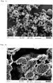
- Porous, polyacrylonitrile-based Si/C composite with conductive carbon black as C additive 5 g conductive carbon black and 20 g polyvinyl acetate dispersion (PVAc) (51% in water) were dispersed at room temperature in 800 ml of an ethanol-water mixture (1:1) using ultrasound (Hielscher UIS250V; amplitude 80%, cycle: 0, 9; duration: 30 min). The resulting dispersion was sprayed and dried (nozzle tip 0.7 mm; nozzle cap 1.4 mm; nozzle temperature 100° C.) using a laboratory spray dryer of type B-290 (BUCHI GmbH) with Inertloop B-295 and dehumidifier B-296 (BUCHI GmbH). ; N 2 gas flow: 30; aspirator 100%; pump 20%).
- PVAc polyvinyl acetate dispersion
- 7.5 g of a black powder were obtained which, according to SEM analysis ( 3 ) consisted of PVAc/conductive carbon black microspheres.
Landscapes
- Chemical & Material Sciences (AREA)
- Electrochemistry (AREA)
- General Chemical & Material Sciences (AREA)
- Chemical Kinetics & Catalysis (AREA)
- Organic Chemistry (AREA)
- Inorganic Chemistry (AREA)
- Composite Materials (AREA)
- Engineering & Computer Science (AREA)
- Manufacturing & Machinery (AREA)
- Materials Engineering (AREA)
- Battery Electrode And Active Subsutance (AREA)
- Silicon Compounds (AREA)
- Carbon And Carbon Compounds (AREA)
Description
- Die Erfindung betrifft Verfahren zur Herstellung von Präkompositpartikeln auf Basis von Siliciumpartikeln, Polyacrylnitril und Kohlenstoff-Additiven.
- Wiederaufladbare Lithium-Ionen-Batterien sind momentan die kommerziell verfügbaren elektrochemischen Energiespeicher mit den höchsten Energiedichten von bis zu 250 Wh/kg. Sie werden vor allem im Bereich der tragbaren Elektronik, für Werkzeuge und auch für Transportmittel, wie beispielsweise Fahrräder oder Automobile, genutzt. Insbesondere für die Anwendung in Automobilen ist es jedoch notwendig, die Energiedichte der Batterien weiter deutlich zu steigern, um höhere Reichweiten der Fahrzeuge zu erreichen.
- Als negatives Elektrodenmaterial ("Anode") wird in der Praxis gegenwärtig vor allem graphitischer Kohlenstoff verwendet. Graphitischer Kohlenstoff zeichnet sich durch seine stabilen Zykleneigenschaften und seine, im Vergleich zu Lithiummetall, das in Lithium-Primärzellen verwendet wird, recht hohe Handhabungssicherheit aus. So erfährt graphitischer Kohlenstoff bei der Ein- und Auslagerung von Lithium nur geringe Volumenänderungen, beispielsweise im Bereich von 10% für die Grenzstöchiometrie von LiC6. Nachteilig ist jedoch seine relativ niedrige elektrochemische Kapazität von theoretisch 372 mAh/g, die nur etwa ein Zehntel der mit Lithiummetall theoretisch erreichbaren elektrochemischen Kapazität entspricht.
- Dagegen besitzt Silicium mit 4199 mAh/g die höchste bekannte Speicherkapazität für Lithium-Ionen. Nachteiligerweise erleiden Silicium enthaltende Elektrodenaktivmaterialien beim Laden bzw. Entladen mit Lithium extreme Volumenänderungen von bis ca.
- 300%. Durch diese Volumenänderung kommt es zu einer starken mechanischen Beanspruchung des Aktivmaterials und der gesamten Elektrodenstruktur, die durch elektrochemisches Mahlen zu einem Verlust der elektrischen Kontaktierung und damit zur Zerstörung der Elektrode unter Kapazitätsverlust führt. Weiterhin reagiert die Oberfläche des eingesetzten Silicium-Anodenmaterials mit Bestandteilen des Elektrolyten unter kontinuierlicher Bildung passivierender Schutzschichten (Solid Electrolyte Interface; SEI), was zu einem irreversiblen Verlust an mobilem Lithium führt.
- Um die Probleme im Zusammenhang mit der starken Volumenausdehnung des Aktivmaterials und der SEI-Bildung in Si-haltigen Anoden zu lösen, wurden in den letzten Jahren verschiedene Ansätze zur elektrochemischen Stabilisierung Si-haltiger Elektrodenaktivmaterialien verfolgt, wie beispielsweise beschrieben von A. J. Appleby in J. Power Sources 2007, 163, Seiten 1003 bis 1039. Vielfach wird Silicium-haltiges Aktivmaterial in Kombination mit Kohlenstoff eingesetzt. In einem Ansatz wird das Si-haltige Aktivmaterial in Form einer physikalischen Mischung mit Graphit in die Elektrodenbeschichtung eingesetzt, wie in
EP 1730800 B1 gelehrt. In einem anderen Ansatz werden die beiden Elemente Silicium und Kohlenstoff strukturell zu einem Komposit-Material verbunden, wie in einem Übersichtsartikel von M. Rossi in J. Power Sources 2014, 246, Seiten 167 bis 177 zusammengefasst. - Für die Verarbeitung sowie die elektrochemische Performance solcher Partikel hat deren Partikelstruktur und Partikelgröße entscheidende Bedeutung. So werden sphärische Mikropartikel auf Basis von Silicium und leitfähigem Kohlenstoff gewünscht, da diese aufgrund ihrer kugelförmigen Struktur die isotrope Volumenausdehnung von Silicium in alle Raumrichtungen gleichmäßiger als nicht sphärische Partikel abpuffern können.
- Die Herstellung von sphärischen, mikroskaligen Si/C-Komposit-partikeln erfolgt in etablierter Weise über einen Sprühtrocknungsschritt. Dazu werden Dispersionen von Siliciumpartikeln, Kohlenstoff-Precursoren (beispielsweise Zucker oder Pech) und gegebenenfalls weiteren Kohlenstoff-haltigen Additiven zu Tröpfchen versprüht, die im Zuge der Trocknung ihre Tropfenform und Tropfengröße bewahren und auf diese Weise sphärische Präkompositpartikel bilden. Anschließende Carbonisierung der Kohlenstoff-Precursoren überführt die Präkompositpartikel in Si-/C-Kompositpartikel. Ein entsprechendes Verfahren ist beispielsweise in der
US 2011165468 beschrieben. Die Sprühtrocknungsverfahren von B. Li führen zu Kompositpartikeln, die im Inneren ein poröses Geflecht aus Kohlenstoff und Si-Nanopartikeln beinhalten (Electrochem. Comm. 2014, 49, 98). F. Su (RSC Adv. 2014, 4, Seiten 43114 bis 43120) beschreibt einen analogen Ansatz unter Einsatz von Leitruß, nano-Silicium und Saccharose. X. Hou (J. Power Sources 2014, 248, Seiten 721 bis 728) beschreibt ein zweistufiges Verfahren zur Herstellung von Si-/C-Kompositpartikeln, in dem zuerst nano-Silicium zusammen mit Graphit und Citronensäure als C-Precursor sprühgetrocknet werden. Die Trocknungsprodukte wurden nach Temperaturbehandlung mit Pech beschichtet, anschließend einer Sprühtrocknung und schließlich einer Pyrolyse unterworfen. Datta et al., Journal of Power Sources, Elsevier SA, CH, Vol. 194, No. 2, 1. Dezember 2009, Seiten 1043-1052 stellen Si/C-Kompositpartikel her, indem zunächst Siliciumpartikel, Polyacrylnitril und Graphit im Lösungsmittel N-Methylpyrrolidon (NMP) gemischt werden, das so erhaltene Produkt anschließend in gemahlenes Pulver überführt und schließlich bei 1073 K thermisches behandelt wird. - Nachteiliger Weise erfordern Sprühtrocknungsprozesse den Einsatz erheblicher Mengen an Lösungsmitteln, häufig organischen Lösungsmitteln, welche während des Sprühvorgangs energieaufwändig verdampft und nach Abtrennung des Produkts wieder kondensiert werden. Lösungsmittel und Sprühgas müssen dann wieder aufwändig getrennt und zurückgeführt werden. Zudem werden für die Zerstäubung von organischen Lösungsmitteln enthaltenden Dispersionen inerte Sprühgases, wie Stickstoff oder Argon, benötigt, was ein weiterer Kostenfaktor ist.
- Bei gängigen Sprühtrocknungsverfahren besteht auch das Problem, dass während der Sprühtrocknung unterschiedliche Partikel miteinander verkleben beziehungsweise verwachsen und dadurch aggregierte Partikel, auch Sekundärpartikel genannt, bilden. Eine weitere Aggregierung von Partikeln kann bei der Carbonisierung herkömmlicher Sprühtrocknungsprodukte durch Versinterung unterschiedlicher Partikel auftreten. Als Ergebnis resultieren Si/C-Kompositpartikel, die keine sphärische Struktur mehr haben sowie erhebliche Anteile an Grobpartikeln enthalten und eine breite Partikelgrößenverteilung aufweisen, was für deren Weiterverarbeitung als Anodenaktivmaterial für Lithium-Ionen-Batterien nachteilig ist.
- Aus diesen Gründen besteht Bedarf an Verfahren, die ohne Einsatz von Lösungsmitteln zu geeigneten Si/C-Kompositpartikeln für Anodenaktivmaterialien führen. Hierzu sind Trockenmischprozesse diskutiert worden, in denen Siliciumpartikel mit weiteren Komponenten in trockener Form vermischt oder vermahlen und anschließend durch thermische Carbonisierung in Si/C-Komposite überführt werden.
- Beispielsweise beschreibt die
US8999581 die Herstellung von Si/G/C-Partikeln, indem zunächst Metalle oder Halbmetalle, wie beispielsweise Silicium, und Graphit (G) mittels einer Rotormühle in assemblierte (Halb)Metall/Graphit-Sphären überführt werden, die assemblierten (Halb)Metall/Graphit-Sphären anschließend mit Pech-basiertem amorphem Kohlenstoff beschichtet werden und das so erhaltene Zwischenprodukt schließlich carbonisiert wird. Ein solches mehrstufiges Misch- und Beschichtungsverfahren ist aufwändig. Zudem sind konkret nur Verfahren unter Einsatz von Lösungsmittel beschrieben. DieCN101339987 beschreibt Verfahren zur Herstellung von Kern-Schale-Partikeln, bei denen zunächst Silicium-Pulver und Graphit durch gemeinsames Mahlen zur Erzeugung des Kern-Partikels gemischt werden und anschließend Bitumen oder Polymere, wie Pech, Teer, Polyvinylalkohol oder Epoxyharz als Kohlenstoff-Precursor für die Schale zugegeben werden. Abschließend erfolgt ein Carbonisieren der Kohlenstoff-Precursoren sowie ein Mahlen und Sieben der Produkte.US2009208844 beschreibt beispielsweise Partikel hergestellt durch Carbonisieren von Mischungen umfassend Aktivmaterialien wie Silicium sowie expandierten Graphit und weiteres Kohlenstoffvorläufermaterial, wie Pech oder organische Polymere, beispielsweise Polyaromaten, Polyvinylalkohol, Phenolharz oder Stärke. Überkorn und Aggregate werden in einem separaten Siebschritt abgetrennt. DieEP2018677 beschreibt Kern-Schale-Kompositpartikel mit einem Kern aus Metallen, wie Silicium, und Metalloxiden sowie einer amorphen Kohlenstoff-Beschichtung sowie einer kristallinen Kohlenstoff-Beschichtung als Schale. Die amorphe Kohlenstoff-Beschichtung wird nach dem CVD-Verfahren oder durch Beschichten des Kerns mit organischen Kohlenstoff-Precursoren, wie Pech, Phenolharze, Polyvinylchlorid oder Polyvinylalkohol, und anschließendes thermisches Carbonisieren aufgebracht. Auch dieWO13155397 WO13155397 - Vor diesem Hintergrund bestand also die Aufgabe, Verfahren zur Herstellung von Präkompositpartikeln und Si/C-Kompositpartikeln zu entwickeln, die ohne Zusatz von Lösungsmitteln auskommen und zu nicht-aggregierten oder möglichst wenig aggregierten Präkompositpartikeln führen, die durch thermische Behandlung bzw. Carbonisieren nicht-aggregierte oder möglichst wenig aggregierte Si/C-Kompositpartikel ergeben. Aufwändiges Abtrennen von Über- oder Unterkorn sollte möglichst vermieden werden. Zudem sollten die Präkompositpartikel in einem technologisch möglichst einfachen, einstufigen Verfahren zugänglich werden.
- Ein Gegenstand der Erfindung sind Verfahren zur Herstellung von Präkompositpartikeln, indem Siliciumpartikel, Polyacrylnitril und ein oder mehrere Kohlenstoff-Additive (C-Additive) ausgewählt aus der Gruppe umfassend Graphit, Fulleren, Kohlenstoff-Fasern, Glaskohlenstoff, Graphen, Aktivkohle, Ruße, Kohlenstoffnanoröhren, Kohlenstoffnanoschäume und Aerographit, gegebenenfalls ein oder mehrere organische Porenbildner und gegebenenfalls ein oder mehrere anorganische Zusatzstoffe,
- je in Form eines Pulvers, gemischt werden, wobei vor und während des Mischens kein Lösungsmittel zugegeben wird, und die anorganischen Zusatzstoffe ausgewählt werden aus der Gruppe umfassend Halogenide der Alkali- und Erdalkalimetalle, Carbonate der Alkalimetalle, Zinkoxid, Magnesiumcarbonat und Nickelsulfid,
- wobei das Polyacrylnitril, die Siliciumpartikel und/oder die C-Additive ganz oder teilweise vor dem Mischen vorgelegt oder ganz oder teilweise während des Mischens zudosiert werden,
- mit der Maßgabe, dass ohne Polyacrylnitril in der Vorlage die Siliciumpartikel und/oder die C-Additive zumindest anteilig gemeinsam mit Polyacrylnitril oder nach Zugabe von Polyacrylnitril zudosiert werden.
- Ein Präkompositpartikel ist allgemein ein Agglomerat basierend auf Siliciumpartikeln, C-Additiven und Polyacrylnitril sowie gegebenenfalls organischen Porenbildnern und gegebenenfalls anorganischen Zusatzstoffen. Agglomerate können unter mechanischer Einwirkung wieder in ihre einzelnen Bestandteile zerfallen.
- Bei Polyacrylnitril kann es sich allgemein um Homopolymere von Acrylnitril oder um Copolymere von Acrylnitril und einem oder mehreren ethylenisch ungesättigten Co-Monomeren handeln. Beispiele für Co-Monomere sind Styrol, Butadien, Acrylate und Methacrylate. Polyacrylnitril basiert vorzugsweise zu mindestens 80 Gew.%, besonders bevorzugt zu mindestens 85 Gew.%, noch mehr bevorzugt zu mindestens 95 Gew.% und am meisten bevorzugt zu mindestens 98 Gew.% auf Acrylnitril. Bevorzugt sind Copolymere aus Methacrylat und mindestens 90 Gew.% Acrylnitril und Copolymere mit mindestens 98 Gew.% Acrylnitril, insbesondere Homopolymere von Acrylnitril.
- Polyacrylnitril lässt sich allgemein durch thermische Behandlung in leitfähige Kohlenstoff-Strukturen überführen.
- Die Präkompositpartikel basieren vorzugsweise zu ≤ 60 Gew.%, besonders bevorzugt ≤ 50 Gew.% und am meisten bevorzugt ≤ 45 Gew.% auf Polyacrylnitril. Die Präkompositpartikel basieren vorzugsweise zu ≥ 5 Gew.%, besonders bevorzugt ≥ 7 Gew.% und am meisten bevorzugt ≥ 10 Gew.% auf Polyacrylnitril. Die vorgenannten Angaben in Gew.% beziehen sich jeweils auf das Gesamtgewicht der Präkompositpartikel.
- Das Gewichtsverhältnis der Siliciumpartikel zu Polyacrylnitril beträgt vorzugsweise ≤ 10, besonders bevorzugt ≤ 5 und am meisten bevorzugt ≤ 3. Das Gewichtsverhältnis der Siliciumpartikel zu C-Additiv beträgt vorzugsweise ≥ 0,01, besonders bevorzugt ≥ 0,05 und am meisten bevorzugt ≥ 0,1.
- Als C-Additive können kristalline, teilkristalline oder vorzugsweise nicht-kristalline (amorphe) Kohlenstoff-Verbindungen eingesetzt werden. Beispiele für kristalline oder teilkristalline C-Additive sind Graphit, expandierter Graphit und Fulleren. Unter nicht-kristallinen (amorphen) C-Additiven versteht man allgemein Kohlenstoff-Fasern, Glaskohlenstoff, Graphen, Aktivkohle, Ruße, Kohlenstoffnanoröhren, Kohlenstoffnanoschäume und Aerographit
- Bevorzugte C-Additive werden ausgewählt aus der Gruppe umfassend Graphit, (Leit-)Ruß, Aktivkohle, Carbon Nanotubes (CNTs), Fullerene und Graphen. Besonders bevorzugte C-Additive sind Graphit, Leitruß und Aktivkohle.
- In einer bevorzugten Ausführungsform werden als C-Additive keine kristallinen oder teilkristallinen Kohlenstoff-Verbindungen, insbesondere kein Graphit eingesetzt.
- Am meisten bevorzugte C-Additive sind Leitruß und Aktivkohle.
- Die Präkompositpartikel basieren vorzugsweise zu ≤ 90 Gew.%, besonders bevorzugt ≤ 85 Gew.% und am meisten bevorzugt ≤ 80 Gew.% auf C-Additiven. Die Präkompositpartikel basieren vorzugsweise zu ≥ 3 Gew.%, besonders bevorzugt ≥ 5 Gew.% und am meisten bevorzugt ≥ 10 Gew.% auf C-Additiven. Die vorgenannten Angaben in Gew.% beziehen sich jeweils auf das Gesamtgewicht der Präkompositpartikel.
- Das Gewichtsverhältnis aus Polyacrylnitril und C-Additiv ist vorzugsweise ≥ 0,1, bevorzugt ≥ 0,4 besonders bevorzugt ≥ 0,7.
- Das Gewichtsverhältnis aus Polyacrylnitril und C-Additiv ist vorzugsweise ≤ 20, besonders bevorzugt ≤ 15 und am meisten bevorzugt ≤ 10.
- Siliciumpartikel können aus elementarem Silicium, einem Siliciumoxid oder einer binären, ternären oder multinären Silicium/Metall-Legierung (mit beispielsweise Li, Na, K, Sn, Ca, Co, Ni, Cu, Cr, Ti, Al, Fe) bestehen. Bevorzugt wird elementares Silicium eingesetzt, insbesondere da dieses eine vorteilhaft hohe Speicherkapazität für Lithium-Ionen aufweist.
- Unter elementarem Silicium ist im Allgemeinen hochreines Polysilicium, mit geringem Anteil an Fremdatomen (wie beispielsweise B, P, As), gezielt mit Fremdatomen dotiertes Silicium (wie beispielsweise B, P, As), aber auch Silicium aus metallurgischer Verarbeitung, welches elementare Verunreinigung (wie beispielsweise Fe, Al, Ca, Cu, Zr, C) aufweisen kann, zu verstehen.
- Falls die Siliciumpartikel ein Siliciumoxid enthalten, dann liegt die Stöchiometrie des Oxids SiOx bevorzugt im Bereich 0 < x < 1,3. Falls die Siliciumpartikel ein Siliciumoxid mit höherer Stöchiometrie enthalten, dann ist dessen Schichtdicke auf der Oberfläche bevorzugt kleiner als 10 nm.
- Wenn die Siliciumpartikel mit einem Alkalimetall M legiert sind, dann liegt die Stöchiometrie der Legierung MySi bevorzugt im Bereich 0 < y < 5. Die Siliciumpartikel können gegebenenfalls prälithiiert sein. Für den Fall, dass die Siliciumpartikel mit Lithium legiert sind, liegt die Stöchiometrie der Legierung LizSi bevorzugt im Bereich 0 < z < 2,2.
- Besonders bevorzugt sind Siliciumpartikel, die ≥ 80 Mol% Silicium und/oder ≤ 20 Mol% Fremdatome, ganz besonders bevorzugt ≤ 10 Mol% Fremdatome enthalten.
- Die Oberfläche der Siliciumpartikel kann gegebenenfalls durch eine Oxidschicht oder durch andere anorganische und organische Gruppen abgedeckt sein. Besonders bevorzugte Siliciumpartikel tragen auf der Oberfläche Si-OH- oder Si-H-Gruppen oder kovalent angebundene organische Gruppen, wie beispielsweise Alkohole oder Alkene.
- Die zur Herstellung der Präkompositpartikel eingesetzten Siliciumpartikel haben volumengewichtete Partikelgrößenverteilungen mit Medianwerten des Durchmessers d50 von vorzugsweise 50 nm bis 50 pm, besonders bevorzugt 100 nm bis 30 µm und am meisten bevorzugt 150 nm bis 10 µm.
- Die volumengewichtete Partikelgrößenverteilung ist bestimmbar durch statische Laserstreuung unter Anwendung des Fraunhofer- oder des Mie-Modells mit dem Messgerät Horiba LA 950 mit Ethanol oder Isopropanol als Dispergiermedium für die Siliciumpartikel.
- Die Siliciumpartikel sind vorzugsweise nicht agglomeriert, insbesondere nicht aggregiert.
- Aggregiert bedeutet, dass sphärische oder weitestgehend sphärische Primärpartikel, wie sie beispielsweise zunächst in Gasphasenprozessen bei der Herstellung der Siliciumpartikel gebildet werden, im weiteren Reaktionsverlauf des Gasphasenprozesses zu Aggregaten zusammenwachsen. Diese Aggregate können im weiteren Reaktionsverlauf Agglomerate bilden. Agglomerate sind eine lose Zusammenballung von Aggregaten. Agglomerate können mit tpyischerweise eingesetzten Knet- und Dispergierverfahren leicht wieder in die Aggregate aufgespalten werden. Aggregate lassen sich mit diesen Verfahren nicht oder nur teilweise in die Primärpartikel zerlegen. Aggregate und Agglomerate haben auf Grund ihrer Entstehung zwangsläufig ganz andere Sphärizitäten und Kornformen als die erfindungsgemäßen Siliciumpartikel. Das Vorliegen von Siliciumpartikeln in Form von Aggregaten oder Agglomeraten kann beispielsweise mittels herkömmlicher Raster-Elektronen-Mikroskopie (REM) sichtbar gemacht werden. Statische Lichtstreuungsmethoden zur Bestimmung der Teilchengrößenverteilungen oder Partikeldurchmessern von Siliciumpartikeln können dagegen nicht zwischen Aggregaten oder Agglomeraten unterscheiden.
- Die Siliciumpartikel haben eine Sphärizität von vorzugsweise 0,3 ≤ ψ ≤ 1, besonders bevorzugt 0,4 ≤ ψ ≤ 1 und am meisten bevorzugt 0,5 ≤ ψ ≤ 1. Die Sphärizität ψ ist das Verhältnis aus der Oberfläche einer Kugel gleichen Volumens zur tatsächlichen Oberfläche eines Körpers (Definition von Wadell). Sphärizitäten können beispielsweise aus herkömmlichen REM-Aufnahmen ermittelt werden.
- Die Siliciumpartikel haben vorzugsweise bestimmte Schüttguteigenschaften. Schüttguteigenschaften sind beispielsweise in der internationalen Norm FEM 2.581 der "Federation Europeenne de la Manutention" beschrieben. In der Norm FEM 2.582 werden die allgemeinen und spezifischen Schüttguteigenschaften hinsichtlich der Klassifizierung definiert. Kennwerte, die die Konsistenz und den Zustand des Gutes beschreiben sind zum Beispiel Kornform und Korngrößenverteilung (FEM 2.581 / FEM 2.582: General characteristics of bulk products with regard to their classification and their symbolization).
- Nach DIN ISO 3435 können Schüttgüter in Abhängigkeit der Beschaffenheit der Kornkanten in sechs unterschiedliche Kornformen untergliedert werden:
- I: scharfe Kanten mit ungefähr gleichen Ausmaßen in den drei Dimensionen (Bsp.: Würfel);
- II: scharfe Kanten, deren eine deutlich länger ist als die anderen beiden (Bsp.: Prisma, Klinge);
- III: scharfe Kanten, deren eine deutlich kleiner ist als die beiden anderen (Bsp.: Platte, Schuppen);
- IV: runde Kanten mit ungefähr gleichen Ausmaßen in den drei Dimensionen (Bsp.: Kugel);
- V: runde Kanten, in einer Richtung deutlich größer als in den anderen beiden (Bsp.: Zylinder, Stange);
- VI: faserig, fadenförmig, lockenförmig, verschlungen.
- Die Siliciumpartikel haben vorzugsweise Kornformen I bis VI, mehr bevorzugt I, II, III oder IV und besonders bevorzugt I oder IV gemäß DIN ISO 3435.
- Die Präkompositpartikel basieren vorzugsweise zu ≤ 70 Gew.%, besonders bevorzugt ≤ 65 Gew.% und am meisten bevorzugt ≤ 60 Gew.% auf Siliciumpartikeln. Die Präkompositpartikel basieren vorzugsweise zu ≥ 5 Gew.%, besonders bevorzugt ≥ 10 Gew.% und am meisten bevorzugt ≥ 15 Gew.% auf Siliciumpartikeln. Die vorgenannten Angaben in Gew.% beziehen sich jeweils auf das Gesamtgewicht der Präkompositpartikel.
- Das Gewichtsverhältnis der Siliciumpartikel zu C-Additiv beträgt vorzugsweise ≤ 4, besonders bevorzugt ≤ 3 und am meisten bevorzugt ≤ 2,5. Das Gewichtsverhältnis der Siliciumpartikel zu C-Additiv beträgt vorzugsweise ≥ 0,1, besonders bevorzugt ≥ 0,2und am meisten bevorzugt ≥ 0,3.
- Die Siliciumpartikel können beispielsweise mittels Gasphasenabscheidung oder vorzugsweise durch Mahlprozesse hergestellt werden.
- Als Mahlprozesse kommen Trocken- oder Nassmahlprozesse in Betracht. Hierbei werden vorzugsweise Strahlmühlen, wie Gegenstrahlmühlen, oder Prallmühlen, Planetenkugelmühlen oder Rührwerkskugelmühlen eingesetzt. Die Strahlmühlen weisen bevorzugt einen integrierten Windsichter auf, der statisch oder dynamisch ausgebildet sein kann, oder sie werden im Kreislauf mit einem externen Windsichter betrieben.
- Die Nassmahlung erfolgt im Allgemeinen in einer Suspension mit organischen oder anorganischen Dispergiermedien. Bevorzugte Dispergiermedien sind die weiter oben beschriebenen Dispergierflüssigkeiten.
- Bei der Nassmahlung werden vorzugsweise Mahlkörper verwendet, deren mittlerer Durchmesser 10 bis 1000 mal größer ist als der 90%-Perzentilwert d90 des Durchmessers des eingesetzten Mahlguts, bezogen auf die Partikelgrößenvolumenverteilung. Besonders bevorzugt sind Mahlkörper, deren mittlerer Durchmesser 20 bis 200-mal größer ist als der d90-Wert der Ausgangsverteilung des Mahlguts.
- Bevorzugte anorganische Zusatzstoffe sind Halogenide der Alkali- und Erdalkalimetalle, Carbonate der Alkalimetalle, Zinkoxid, Magnesiumcarbonat und Nickelsulfid. Die anorganischen Zusatzstoffe können beispielsweise als Porenbildner dienen. Porenbildner können in herkömmlicher Weise aus den Partikeln freigesetzt werden unter Bildung von Partikeln mit größerer Porosität.
- Die Präkompositpartikel basieren vorzugsweise zu 0 bis 25 Gew.% und besonders bevorzugt 2 bis 20 Gew.% auf anorganischen Zusatzstoffen, bezogen auf das Gesamtgewicht der Präkompositpartikel. Am meisten bevorzugt enthalten die Präkompositpartikel keine anorganischen Zusatzstoffe und/oder keine sonstigen anorganischen Bestandteile.
- Zusätzlich können ein oder mehrere organische Porenbildner eingesetzt werden. Typische organische Porenbildner haben bei einer Temperatur ausgewählt aus dem Bereich von 25 bis 1000°C einen Masseverlust von ≥ 50 Gew.-%, bevorzugt ≥ 80 Gew.-% und besonders bevorzugt ≥ 90 Gew.-%.
- Beispiele für organische Porenbildner sind Homo- oder Copolymere von ethylenisch ungesättigten Monomeren, beispielsweise Polyethylen, Polypropylen, Polystyrol, Polybutadien, Poly-tert-Butoxystyrol, Polyvinylchlorid, Polyvinylacetat, Polymethylmethacrylat, Polyacrylsäure, Polymethacrylat, Polyvinylstearat Polyvinyllaurat oder deren Copolymere; Polyvinylalkohol; Alkylenglycole, wie Ethylenglycol, Butylengylcol, Diethylengylcol, Triethylenglycol; Polyalkylenoxide, wie Polyethylenoxide, Polypropylenoxide oder deren Copolymere; Lignin, Polysaccharide, Phenol-Harze, Melaminharze, Resorcin-Harze oder Polyurethane Bevorzugte Porenbildner werden ausgewählt aus der Gruppe umfassend Polyethylen, Polystyrol, Polymethylmethacrylat, Alkylenglycole und Polyalkylenoxide, wie Polyethylenoxid, Polypropylenoxid und Polyethylenoxid-Polypropylenoxid-Copolymere, Polyvinylacetat, Styrol-Butadien-Copolymer.
- Die Präkompositpartikel basieren vorzugsweise zu 0 bis 60 Gew.%, besonders bevorzugt 5 bis 55 Gew.% und am meisten bevorzug 10 bis 50 Gew.% auf organischen Porenbildnern, bezogen auf das Gesamtgewicht der Präkompositpartikel.
- Porenbildner enthaltende Präkompositpartikel führen zu Si/C-Kompositpartikeln, die bei Einsatz in Anodenaktivmaterialien von Lithiumionen-Batterien die Coulomb-Effizienz oder die elektrochemische Stabilität steigern.
- Die Mischungen können auch ein oder mehrere Additive enthalten, wie beispielsweise Verlaufsmittel, Dotiermittel oder Stoffe, die die elektrochemische Stabilität der Elektrode in der Batterie verbessern.
- Die Präkompositpartikel basieren vorzugsweise zu 0 bis 50 Gew.%, besonders bevorzugt 1 bis 40 Gew.% und am meisten bevorzugt 2 bis 30 Gew.% auf Additiven, bezogen auf das Gesamtgewicht der Präkompositpartikel. In einer bevorzugten, alternativen Ausführungsform enthalten die Präkompositpartikel keine Additive.
- Die Präkompositpartikel fallen vorzugsweise in Form von isolierten Partikeln oder lockeren Agglomeraten von Präkompositpartikeln an, jedoch im Allgemeinen nicht in Form von Aggregaten von Präkompositpartikeln. Agglomerate sind Zusammenballungen von mehreren Präkompositpartikeln. Aggregate sind Zusammenlagerungen von Präkompositpartikeln. Agglomerate lassen sich in die einzelnen Präkompositpartikel separieren, beispielsweise mit Knet- oder Dispergierverfahren. Aggregate lassen sich auf diese Weise nicht in die einzelnen Partikel trennen, ohne Präkompositpartikel zu zerstören.
- Die Präkompositpartikel liegen vorzugsweise in Form von Kern-Schale-Partikeln vor. Polyacrylnitril bildet vorzugsweise den Kern. Die Schale wird vorzugsweise von Siliciumpartikeln und/oder C-Additiv gebildet. Durch Einwirkung von Ultraschall lassen sich die Kern-Schale-Partikel wieder in ihre Ausgangsstoffe deagglomerieren.
- Die Präkompositpartikel sind bevorzugt sphärisch, können aber auch eine Splitterform aufweisen. Die Präkompositpartikel haben eine Sphärizität von vorzugsweise 0,3 ≤ ψ ≤ 1, besonders bevorzugt 0,5 ≤ ψ < 1 und am meisten bevorzugt 0,8 ≤ ψ ≤ 1. Die Sphärizität ψ ist das Verhältnis aus der Oberfläche einer Kugel gleichen Volumens zur tatsächlichen Oberfläche eines Körpers (Definition von Wadell). Sphärizitäten können beispielsweise aus herkömmlichen REM-Aufnahmen ermittelt werden.
- Die Siliciumpartikel, Polyacrylnitril, die C-Additive sowie die optionalen organischen Porenbildner, anorganischen Zusatzstoffe und Additive werden im Allgemeinen in Form von Pulvern eingesetzt. Unter Pulver werden allgemein kleinteilige, partikuläre, trockene Feststoffe verstanden. Pulver können unterschiedliche Formen annehmen, wie beispielsweise Puder-, Körner- oder sonstige Partikel-Formen.
- Bei der Herstellung der Präkompositpartikel wird allgemein kein Lösungsmittel zugesetzt. Das Verfahren wird also im Allgemeinen in Abwesenheit von Lösungsmittel durchgeführt. Dies schließt jedoch nicht aus, dass die eingesetzten Edukte, beispielsweise in Folge ihrer Herstellung, etwaige Restgehalte an Lösungsmittel enthalten. Vorzugsweise enthalten die Siliciumpartikel, Polyacrylnitril, die C-Additive, die organischen Porenbildner, die anorganischen Zusatzstoffe, die Additive und/oder die Präkomposite ≤ 2 Gew.%, besonders bevorzugt ≤ 1 Gew.% und am meisten bevorzugt ≤ 0,5 Gew.% Lösungsmittel.
- Beispiele für Lösungsmittel sind anorganische Lösungsmittel, wie Wasser, oder organische Lösungsmittel, insbesondere Kohlenwasserstoffe, Ether, Ester, Stickstoff-funktionelle Lösungsmittel, Schwefel-funktionelle Lösungsmittel oder Alkohole mit vorzugsweise 1 bis 12 Kohlenstoffatomen und besonders bevorzugt 1 bis 8 Kohlenstoffatomen. Konkrete Beispiele für Lösungsmittel sind Wasser, Ethanol und 2-Propanol, Dimethylformamid, N-Methyl-2-Pyrrolidon, N-Ethyl-2-Pyrrolidon und Dimethylsulfoxid.
- Die Siliciumpartikel, Polyacrylnitril und die C-Additive sowie die optionalen organischen Porenbildner, anorganischen Zusatzstoffe und Additive werden im Folgenden gemeinsam auch als Ausgangsstoffe bezeichnet.
- Zur Herstellung der Präkompositpartikel werden die unterschiedlichen Ausgangsstoffe vermischt oder vermahlen.
- Die Siliciumpartikel, Polyacrylnitril und die C-Additive sowie gegebenenfalls die weiteren Ausgangsstoffe können vor dem Mischen oder Mahlen teilweise oder vorzugsweise vollständig vorgelegt werden. Polyacrylnitril wird vorzugsweise teilweise und besonders bevorzugt vollständig vor dem Mischen oder Mahlen vorgelegt. Die Siliciumpartikel, die C-Additive und Polyacrylnitril werden vorzugsweise zu ≥ 10 Gew.-%, besonders bevorzugt ≥ 20 Gew.-% und am meisten bevorzugt ≥ 30 Gew.-% vorgelegt, bezogen auf das Gesamtgewicht der Ausgangsstoffe. Polyacrylnitril wird vorzugsweise zu ≥ 40 Gew.-%, besonders bevorzugt ≥ 60 Gew.-% und am meisten bevorzugt ≥ 70 Gew.-% vorgelegt, bezogen auf das Gesamtgewicht des insgesamt eingesetzten Polyacrylnitrils.
- Alternativ können Polyacrylnitril und insbesondere die Siliciumpartikel, die C-Additive sowie die gegebenenfalls eingesetzten weiteren Ausgangsstoffe vollständig oder anteilig während des Mischens oder Mahlens zudosiert werden.
- Falls Polyacrylnitril teilweise zudosiert wird und insbesondere falls Polyacrylnitril vollständig zudosiert wird, wird vorzugsweise die insgesamt eingesetzte Menge an Siliciumpartikeln und/oder C-Additiven oder ein Anteil davon gleichzeitig mit Polyacrylnitril zudosiert und/oder nach der vollständigen Zugabe von Polyacrylnitril zudosiert.
- Bei teilweisem und insbesondere bei vollständigem Zudosieren von Polyacrylnitril werden nach Ende der Zudosierung von Polyacrylnitril noch vorzugsweise 0 bis 50 Gew.-% und besonders bevorzugt 0,1 bis 30 Gew.-% an Siliciumpartikeln und/oder C-Additiven zudosiert, bezogen auf das Gesamtgewicht der insgesamt eingesetzten Menge an Siliciumpartikeln und C-Additiven.
- Im Allgemeinen wird also nach vollständiger Zugabe der Siliciumpartikel und der C-Additive kein Polyacrylnitril mehr zudosiert.
- Ansonsten können die einzelnen Ausgangsstoffe in beliebiger Reihenfolge, also räumlich getrennt oder räumlich gemeinsam, zeitlich nacheinander oder gleichzeitig, vor oder während des Mischens in die Mischvorrichtung eingebracht werden. Vorzugsweise werden alle Ausgangsstoffe räumlich getrennt, vor oder während des Mischens, gegebenenfalls gleichzeitig in die Mischvorrichtung eingebracht.
- Alternativ kann auch eine Vormischung aus ein oder mehreren unterschiedlichen Ausgangsstoffen hergestellt werden, die anschließend mit den verbleibenden Ausgangsstoffen gemischt werden. Eine Vormischung enthält vorzugsweise ein oder mehrere C-Additive und ein oder mehrere organische Porenbildner.
- Besonders bevorzugt werden alle Ausgangsstoffe gleichzeitig dem Mischen unterworfen.
- Es können gängige Mischer, insbesondere industrielle Mischer Einsatz finden. Beispiele für Mischer sind Freifallmischer, wie Containermischer, Konusmischer, Fassrollmischer, Rhönradmischer, Taumelmischer oder Schub- und Wurfmischer wie Trommelmischer und Schneckenmischer. Weitere Beispiele für geeignete Mischer sind in "Mischen von Feststoffen" von R. Weinekötter und H. Gericke, Springer 1995 angeführt. Alternativ können hierfür auch gängige Mühlen eingesetzt werden, wie zum Beispiel Planetenkugelmühlen, Rührwerkskugelmühlen oder Trommelmühlen. Bevorzugt werden Schneckenmischer, Trommelmischer oder Trommelmühlen eingesetzt.
- Das Mischen erfolgt vorzugsweise bei Temperaturen von 0 bis 50°C und besonders bevorzugt 15 bis 35°C. Jedenfalls erfolgt das Mischen bei Temperaturen von vorzugsweise ≤ 300°C, mehr bevorzugt ≤ 200°C und besonders bevorzugt ≤ 100°C. Die Dauer des Mischens beträgt vorzugsweise 0,5 bis 20 Stunden, besonders bevorzugt 1 bis 15 Stunden und am meisten bevorzugt 1,5 bis 10 Stunden.
- Durch die thermische Behandlung werden die Präkompositpartikel in Si/C-Kompositpartikel überführt. Hierbei erfolgt im Allgemeinen eine Carbonisierung von Polyacrylnitril. Polyacrylnitril wird dabei vorzugsweise in anorganischen Kohlenstoff überführt. Die Kohlenstoffausbeute beim Carbonisieren von Polyacrylnitril beträgt vorzugsweise ≥ 15%, besonders bevorzugt ≥ 20% und am meisten bevorzugt ≥ 25%, bezogen auf das Gesamtgewicht von Polyacrylnitril. Der Kohlenstoff in den Si/C-Kompositpartikeln kann kristallin oder amorph vorliegen sowie Mischungen aus kristallinen und amorphen Bestandteilen enthalten.
- Auf Grund der Herstellung der Si/C-Komposit-partikel sind darin die Siliciumpartikel und die C-Additive im Allgemeinen vollständig oder teilweise in Kohlenstoff eingebettet. Die Oberfläche der Si/C-Kompositpartikel besteht vorzugsweise vollständig oder teilweise, besonders bevorzugt im Wesentlichen aus Kohlenstoff.
- Die Si/C-Kompositpartikel fallen vorzugsweise in Form von isolierten Partikeln oder lockeren Agglomeraten von Si/C-Komposit-partikeln an, jedoch im Allgemeinen nicht in Form von Aggregaten von Si/C-Kompositpartikeln. Etwaige Agglomerate von Si/C-Kompositpartikeln lassen sich in die einzelnen Si/C-Komposit-partikel separieren, beispielsweise durch Knet- oder Dispergierverfahren. Dagegen lassen sich Aggregate von Si/C-Kompositpartikeln auf diese Weise nicht in die einzelnen Partikel trennen, ohne Si/C-Kompositpartikel zu zerstören.
- Die Si/C-Kompositpartikel weisen typischerweise BET-Oberflächen auf von bevorzugt 1 bis 200 m2/g, besonders bevorzugt 2 bis 150 m2/g und am meisten bevorzugt 5 bis 100 m2/g (Bestimmung nach DIN ISO 9277:2003-05).
- Die Si/C-Kompositpartikel sind bevorzugt sphärisch, können aber auch eine Splitterform aufweisen. Die Si/C-Kompositpartikel haben eine Sphärizität von vorzugsweise 0,3 ≤ ψ ≤ 1, besonders bevorzugt 0,5 ≤ ψ ≤ 1 und am meisten bevorzugt 0,8 ≤ ψ ≤ 1. Die Sphärizität ψ ist das Verhältnis aus der Oberfläche einer Kugel gleichen Volumens zur tatsächlichen Oberfläche eines Körpers (Definition von Wadell). Sphärizitäten können beispielsweise aus herkömmlichen REM-Aufnahmen ermittelt werden.
- Die Si/C-Kompositpartikel haben volumengewichtete Partikelgrößenverteilungen mit Durchmesser-Perzentilen d50 von vorzugsweise ≥ 0,5 pm, besonders bevorzugt ≥ 1 µm und am meisten bevorzugt ≥ 2 µm. Die Si/C-Kompositpartikel haben d50-Werte von vorzugsweise ≤ 100 µm, mehr bevorzugt ≤ 50 µm, besonders bevorzugt ≤ 36 µm und am meisten bevorzugt ≤ 20 µm.
- Die Partikelgrößenverteilung der Si/C-Kompositpartikel kann bimodal oder polymodal sein und ist bevorzugt monomodal, besonders bevorzugt schmal. Die volumengewichtete Partikelgrößenverteilung der Si/C-Kompositpartikel hat eine Breite (d90-d10) /d50 von bevorzugt ≤ 3, mehr bevorzugt ≤ 2,5, besonders bevorzugt ≤ 2 und am meisten bevorzugt ≤ 1,5.
- Die Bestimmung der volumengewichteten Partikelgrößenverteilung der Si/C-Kompositpartikel erfolgte durch statische Laserstreuung unter Anwendung des Mie-Modells mit dem Messgerät Horiba LA 950 mit Ethanol als Dispergiermedium für die Si/C-Kompositpartikel.
- Die Si/C-Kompositpartikel weisen einen Aggregationsgrad von bevorzugt ≤ 20%, besonders bevorzugt ≤ 15% und am meisten bevorzugt ≤ 10% auf. Bestimmt wird der Aggregationsgrad durch eine Siebanalyse. Der Aggregationsgrad entspricht dem Prozentsatz der Partikel, die nach Dispersion in Ethanol bei gleichzeitiger Ultraschallbehandlung nicht durch ein Sieb mit einer Maschenweite von 20 µm hindurch treten.
- Die Si/C-Kompositpartikel sind vorzugsweise porös. Die Si/C-Kompositpartikel enthalten Poren mit Durchmessern von vorzugsweise ≥ 60 nm, besonders bevorzugt ≥ 100 nm und am meisten bevorzugt ≥ 200 nm. Die Poren haben Durchmesser von vorzugsweise ≤ 1400 nm, besonders bevorzugt ≤ 700 nm und am meisten bevorzugt ≤ 400 nm (Bestimmungsmethode: Raster-Elektronen-Mikroskopie (REM)).
- Besonders bevorzugt befinden sich Siliciumpartikel in Poren. Der Anteil der Siliciumpartikel, die sich in Poren befinden, beträgt vorzugsweise ≥ 5%, besonders bevorzugt ≥ 20% und am meisten bevorzugt ≥ 50%, bezogen auf die Gesamtzahl der Siliciumpartikel in den Si/C-Kompositpartikeln (Bestimmungsmethode: Raster-Elektronen-Mikroskopie (REM)).
- Die Si/C-Kompositpartikel basieren zu vorzugsweise 5 bis 50 Gew.-%, besonders bevorzugt 10 bis 40 Gew.-%, am meisten bevorzugt 20 bis 40 Gew.-% auf Silicium; vorzugsweise 50 bis 95 Gew.-%, besonders bevorzugt 60 bis 85 Gew%, am meisten bevorzugt 60 bis 80 Gew.-% Kohlenstoff. Weiterhin können SauerstoffGehalte von beispielsweise ≤ 20 Gew.-%, bevorzugt ≤ 10 Gew.-% und besonders bevorzugt ≤ 5 Gew.-% enthalten sein, beispielsweise in Form einer nativen SiO2-Schicht auf den Siliciumpartikeln. Gewisse Mengen an Stickstoff in den Si/C-Kompositpartikeln sind vorteilhaft und betragen beispielsweise 0,5 bis 10 Gew.-% und besonders bevorzugt zwischen 2 bis 5 Gew.-% Stickstoff liegt hierbei vorzugsweise chemisch gebunden in Form von Heterocyclen vor, beispielsweise als Pyridin- oder Pyrrol-Einheiten (N). Neben den genannten Hauptbestandteilen können auch weitere chemische Elemente in Form eines gezielten Zusatzes oder zufälliger Verunreinigung enthalten sein: wie beispielsweise Li, Fe, Al, Cu, Ca, K, Na, S, Cl, Zr, Ti, Pt, Ni, Cr, Sn, Mg, Ag, Co, Zn, B, P, Sb, Pb, Ge, Bi, Seltene Erden; deren Gehalte sind bevorzugt ≤ 1 Gew.-% und besonders bevorzugt ≤ 100 ppm. Die vorgenannten Angaben in Gew.% beziehen sich jeweils auf das Gesamtgewicht der Si/C-Kompositpartikel. Die Angaben in Gew.-% beziehen sich jeweils auf das Gesamtgewicht der Si/C-Kompositpartikel.
- Die thermische Behandlung der Präkompositpartikel erfolgt bei Temperaturen von vorzugsweise 400 bis 1400°C, besonders bevorzugt 700 bis 1200°C und am meisten bevorzugt 900 bis 1100°C.
- Die thermische Behandlung kann beispielsweise in einem Rohrofen, Glühofen, Drehrohrofen oder einem Wirbelschichtreaktor stattfinden. Durch Wahl des Reaktortyps kann die Carbonisierung statisch oder unter ständiger Durchmischung des Reaktionsmediums durchgeführt werden.
- Die thermische Behandlung kann unter aeroben oder anaeroben Bedingungen stattfinden. Beispielsweise kann eine erste thermische Behandlung bei Temperaturen bis 300°C unter Sauerstoffhaltiger Atmosphäre und eine zweite thermische Behandlung bei Temperaturen > 300°C unter Inertgas-Atmosphäre durchgeführt werden. Die thermische Behandlung wird vorzugsweise in einer Inertgas-Atmosphäre, wie Stickstoff- oder vorzugsweise ArgonAtmosphäre, durchgeführt. Die Inertgas-Atmosphäre kann gegebenenfalls zusätzlich Anteile eines reduzierenden Gases, wie Wasserstoff, enthalten. Die thermische Behandlung erfolgt vorzugsweise anaerob. Die Inertgas-Atmosphäre kann sich statisch über dem Reaktionsmedium befinden oder in Form eines Gasflusses über die Reaktionsmischung strömen. Die Flussraten betragen hierbei vorzugsweise bis zu 1 Liter pro Minute, besonders bevorzugt 100 bis 600 mL/min und am meisten bevorzugt 200 bis 250 mL/min, insbesondere im Falle der Carbonisierung von 2 bis 150 g Präkompositpartikel oder einem Reaktorvolumen von 7000 bis 11000 cm3. Die Heizraten beim Aufheizen der Reaktionsmischung betragen vorzugsweise 1 bis 20°C pro Minute, mehr bevorzugt 1 bis 15°C/min, besonders bevorzugt 1 bis 10°C/min und am meisten bevorzugt 3 bis 5°C/min. Weiterhin ist auch ein stufenweiser Prozess mit verschiedenen Zwischentemperaturen und -heizraten möglich. Nach Erreichen der Zieltemperatur wird die Reaktionsmischung üblicherweise eine gewisse Zeit bei der Temperatur getempert oder anschließend sogleich abgekühlt. Vorteilhaft sind Haltedauern von beispielsweise 30 min bis 24 h, bevorzugt 1 bis 10 h und besonders bevorzugt 2 bis 3 h. Das Abkühlen kann aktiv oder passiv, gleichmäßig oder stufenweise durchgeführt werden.
- Die so erhaltenen Si/C-Kompositpartikel können unmittelbar ihrer weiteren Verwertung zugeführt werden, beispielsweise zur Herstellung von Elektrodenmaterialien, oder alternativ zuerst mechanisch, beispielsweise durch Mahlung oder Siebung, nachbehandelt oder durch Klassierungstechniken (Sieben, Sichten) von Über- oder Unterkorn befreit werden. Vorzugsweise unterbleiben mechanische Nachbehandlungen oder Klassierung, insbesondere unterbleibt ein Mahlen, Sieben oder Sichten.
- Die Oberfläche der Si/C-Kompositpartikel kann auch modifiziert werden, beispielsweise durch Aufbringen einer oder mehrerer Beschichtungen, insbesondere einer Kohlenstoffbeschichtung. Hierzu können die Si/C-Kompositpartikel zuerst mit einem oder mehreren Kohlenstoff-Precursoren beschichtet und anschließend eine Carbonisierung durchgeführt werden. Kohlenstoff-Precursoren sind beispielsweise Teere oder Peche, insbesondere hochschmelzende Peche, HardCarbon (nicht-graphitisierbar bei Temperaturen von 2500 bis 3000°C), SoftCarbon (graphitisierbar bei Temperaturen von 2500 bis 3000°C). Die Carbonisierung kann beispielsweise erfolgen wie die weiter oben beschriebene thermische Behandlung zur Carbonsierung der Präkompositpartikel. Alternativ können die Si/C-Kompositpartikel nach herkömmlichen CVD-Verfahren (chemical vapor deposition; chemische Gasphasenabscheidung) mit Kohlenwasserstoffen mit 1 bis 20 Kohlenstoffatomen als Kohlenstoff-Precursoren beschichtet werden. Auf diese Weise werden Kohlenstoff-beschichtete Si/C-Kompositpartikel erhalten.
- Die so erhaltene Kohlenstoff-Beschichtung der Si/C--Kompositpartikel hat vorzugsweise eine Porosität von ≤ 2% und besonders bevorzugt ≤ 1% (Bestimmungsmethode der Gesamtporosität: 1 minus [Quotient aus Rohdichte (bestimmt mittels Xylol-Pyknometrie gemäß DIN 51901) und Skelettdichte (bestimmt mittels He-Pyknometrie gemäß DIN 66137-2)]).
- Die Kohlenstoff-Beschichtung der Si/C-Kompositpartikel ist im Allgemeinen undurchlässig für flüssige Medien, wie wässrige oder organische Lösungsmittel oder Lösungen, insbesondere wässrige oder organische Elektrolyte, Säuren oder Laugen.
- Die Si/C-Kompositpartikel eignen sich beispielsweise als Silicium-basierte Aktivmaterialien für Anodenaktivmaterialien für Lithium-Ionen-Batterien.
- Die Si/C-Kompositpartikel können als Silicium-Komponente für Elektrodenmaterialien von Lithiumionen-Batterien eingesetzt werden. Die Herstellung entsprechender Lithiumionen-Batterien kann beispielsweise erfolgen wie in der
WO 2015/117838 beschrieben. - Vorteilhafter Weise sind die Präkompositpartikel nach dem erfindungsgemäßen Verfahren ausgehend von am Markt verfügbaren Ausgangsstoffen in einem einstufigen Verfahren ohne Einsatz von Lösungsmittel zugänglich. Der in sonstigen Verfahren zur Herstellung von Präkompositpartikeln übliche Schritt der Sprühtrocknung mit dem damit verbundenen Einsatz an Lösungsmitteln und Aufwand für die Reinigung von Sprühgasen kann somit entfallen.
- Durch Carbonisierung der Präkompositpartikel können Si/C-Kompositpartikel erhalten werden, in denen die Siliciumpartikel und das Kohlenstoff-Additiv in eine amorphe Kohlenstoff-Matrix eingebettet sind.
- Überraschenderweise können nach dem erfindungsgemäßen, lösungsmittelfreien Verfahren Präkompositpartikel zugänglich werden, die hinsichtlich Partikelgrößen den entsprechenden Sprühtrocknungsprodukten gleichen. Zudem sind die unterschiedlichen Komponenten in den Partikeln homogen verteilt. Ein Verkleben oder Versintern und damit eine Aggregierung unterschiedlicher Partikel trat überraschenderweise nicht auf. Dies war umso überraschender, da Polyacrylnitril auch Bindemitteleigenschaften hat. Deswegen war zu befürchten, dass die einzelnen Komponenten verkleben und Produkte erhalten werden, die für Anodenaktivmaterialien völlig unbrauchbar sind. Überraschenderweise trat diese Befürchtung beim erfindungsgemäßen Einsatz der erfindungsgemäßen Komponenten zur Herstellung der Präkompositpartikel und der Si/C-Kompositpartikel nicht ein.
- Interessanterweise fallen die einzelnen Präkompositpartikel als lockere Agglomerate an, die sich beispielsweise mittels Ultraschallbehandlung wieder in ihre Einzelbestandteile separieren lassen, aber nach Carbonisieren Si/C-Kompositpartikel ergeben, die die gewünschte mechanische Stabilität aufweisen, und aus denen die Einzelkomponenten nicht mehr isoliert werden können.
- Die hergestellten Si/C-Kompositpartikel weisen die für Anodenaktivmaterialien von Lithiumionen-Batterien geforderten Eigenschaften auf, wie Partikelgrößen und Partikelgrößenverteilungen. Aufwändiges Mahlen und Sieben kann unterbleiben.
- Die nachfolgenden Beispiele dienen zur weiteren Erläuterung der Erfindung.
- Folgende analytische Methoden und Geräte wurden zur Charakterisierung der erhaltenen Si/C-Komposite eingesetzt:
Rasterelektronemikroskopie (REM/EDX):
Die mikroskopischen Untersuchungen wurden mit einem Rasterelektronemikroskop Zeiss Ultra 55 und einem energiedispersivem Röntgenspektrometer INCA x-sight durchgeführt. Die Proben wurden vor der Untersuchung zur Verhinderung von Aufladungsphänomenen mit einem Baltec SCD500 Sputter-/Carbon-Coating mit Kohlenstoff bedampft. Die in den Figuren gezeigten Querschnitte der Si/C-Kompositpartikel wurden mit einem Ionencutter Leica TIC 3X bei 6 kV erzeugt. - Anorganische Analytik / Elementaranalyse:
Die in den Beispielen angegebenen C-Gehalte wurden mit einem Leco CS 230 Analysator ermittelt, zur Bestimmung von O- und gegebenenfalls N- bzw. H-Gehalten wurde ein Leco TCH-600 Analysator eingesetzt. Die qualitative und quantitative Bestimmung von anderen angegebenen Elementen in den Si/C-Kompositpartikeln wurden mittels ICP (inductively coupled plasma)-Emissionspektrometrie (Optima 7300 DV, Fa. Perkin Elmer) bestimmt. Die Proben wurden dazu in einer Mikrowelle (Microwave 3000, Fa. Anton Paar) sauer aufgeschlossen (HF/HNO3) . Die ICP-OES-Bestimmung orientiert sich an der ISO 11885 "Wasserbeschaffenheit - Bestimmung von ausgewählten Elementen durch induktiv gekoppelte Plasma-Atom-Emissionsspektrometrie (ICP-OES) (ISO 11885:2007); Deutsche Fassung EN ISO 11885:2009", die zur Untersuchung saurer, wässriger Lösungen eingesetzt wird. - Partikelgrößenbestimmung:
Die Bestimmung der Partikelgrößenverteilung erfolgte im Rahmen dieser Erfindung nach ISO 13320 mittels statischer Laserstreuung mit einem Horiba LA 950. Dabei muss bei der Vorbereitung der Proben besondere Sorgfalt auf die Dispergierung der Partikel in der Messlösung aufgewendet werden, um statt Einzelpartikel nicht die Größe von Agglomeraten zu messen. Hierzu wurden die Si/C-Kompositpartikel in Ethanol dispergiert, und die Dispersion wurde vor der Messung 4 min in einem Hielscher Ultraschall-Laborgerät Modell UIS250v mit Sonotrode LS24d5 mit 250 W Ultraschall behandelt. - Sofern nicht anders angegeben, wurden die nachstehenden (Vergleichs)Beispiele in Umgebungsluft, bei 1013 mbar und 23 °C durchgeführt. Die folgenden Methoden fanden Einsatz in den Beispielen:
Carbonisierung:
Alle in den Beispielen durchgeführten Carbonisierungen wurden mit einem 1200 °C Drei-Zonen Rohrofen (TFZ 12/65/550/E301) der Fa. Carbolite GmbH unter Verwendung einer Kaskadenregelung inklusive eines Probenthermoelements Typ N durchgeführt. Die angegebenen Temperaturen beziehen sich auf die Innentemperatur des Rohrofens am Ort des Thermoelements. Das jeweils zu carbonisierende Ausgangsmaterial wurde in ein oder mehrere Verbrennungsschiffchen aus Quarzglas (QCS GmbH) eingewogen und in ein Arbeitsrohr aus Quarzglas eingebracht. Die für die Carbonisierungen verwendeten Einstellungen und Prozessparameter sind in den jeweiligen (Vergleichs)Beispielen angegeben. - Klassierung/Siebung:
Die nach der Carbonsierung erhaltenen Si/C-Kompositpartikel wurden durch Nasssiebung mit einer Siebmaschine AS 200 basic (Retsch GmbH) mit Wasser an Edelstahlsieben von Überkorn > 20 µm befreit. Das Kompositpulver wurde in Ethanol mittels Ultraschall (Hielscher UIS250V; Amplitude 80%, Cycle: 0,75; Dauer: 30 min) dispergiert (20% Feststoffgehalt) und auf den Siebturm mit einem Sieb (20 pm) aufgebracht. Die Siebung wurde mit einer unendlichen Zeitvorwahl und einer Amplitude von 50-70% bei durchlaufendem Wasserstrom durchgeführt. Die unten austretende, Komposit-haltige Suspension wurde über 200 nm-Nylonmembran filtriert, und der Filterrückstand im Vakuumtrockenschrank bei 100°C und 50-80 mbar bis zur Massenkonstanz getrocknet. - Folgende Materialien wurden aus kommerziellen Quellen bezogen bzw. selber hergestellt und ohne weitere Reinigung direkt eingesetzt:
getrocknetes Silicium-Nanopulver (splitterförmige, nicht-aggregierte Si-Partikel selbst hergestellt durch Nassmahlung in einer Rührwerkskugelmühle in 2-Propanol (Feststoffgehalt 15,7 Gew.%, D50 = 200 nm)), Polyacrylnitril (H-PAN; Mw = 200.000; D50 = 48 µm; Fa. Dolan), Leitruß (Super P, Fa. Imerys/Timcal), Graphit (KS6L, Fa. Imerys), Aktivkohle (Contarbon, Fa. Donau-Carbon, vermahlen auf D50=5µm), Pech (hochschmelzend; Erweichungspunkt 235 °C), Polyvinylchlorid (PVC) (Fa. Sigma-Aldrich, Art-Nr. 389293); Polyvinylacetat-Dispersion (Vinnapas EAF380; Fa. Wacker Chemie AG). - Polyacrylnitril-basiertes Si/C-Komposit mit Leitruß als C-Additiv:
5,4 g Polyacrylnitril-Pulver (PAN), 5,4 g Leitruß und 6,0 g trockenes Silicium-Nanopulver (D50: 200 nm) wurden zusammen mit 3 Zirkonoxid-Kugeln (20 mm Durchmesser) in einem Polypropylenbecher (125 ml) gegeben, und der Inhalt des Bechers wurde auf einem Labor-Rollenmischer (Typ SRT6D, Fa. Stuart) bei 125 rpm innerhalb von 14 h durchmischt. - Es wurde ein Si/Leitruß/PAN-Pulvermischung in Form von Agglomeraten erhalten.
- Durch Einwirken von Ultraschall lässt sich das Agglomerat wieder trennen und man erhält die bimodale Partikelgrößenverteilung, die den Ausgangskomponenten zuzuordnen ist.
- 13,7 g der Si/Leitruß/PAN-Pulvermischung in Form von Agglomeraten wurden in ein Quarzglasschiffchen (QCS GmbH) gegeben und in einem Drei-Zonen-Rohrofen (TFZ 12/65/550/E301; Fa. Carbolite) unter Verwendung einer Kaskadenregelung inklusive eines Probenelements Typ N mit Formiergas (95% N2, 5% H2) als Inertgas carbonisiert: zuerst Heizrate 10 °C/min, Temperatur 300 °C, Haltedauer 90 min, N2/H2-Flussrate 200 ml/min; danach direkt weiter mit Heizrate 10 °C/min, Temperatur 1000 °C, Haltedauer 3 h, N2/H2-Flussrate 200 ml/min. Nach dem Abkühlen wurden 11,2 g eines schwarzen Pulvers erhalten (82% Ausbeute bezogen auf Einwaage), wovon 11,0 g durch Siebung von Überkorn > 20 µm befreit wurde.
- Es wurden 10,2 g eines schwarzen Pulvers < 20 µm (Aggregationsgrad 7%) erhalten, das laut REM-Analytik (
Fig. 1 ) aus nicht-aggregierten, mikroskaligen Si/C-Komposit-Partikeln bestand, die im Inneren Leitruß- und Nano-Si-Partikel enthielten und eine monomodale Partikelgrößenverteilung aufwiesen. - Elementare Zusammensetzung: Si 41,6 Gew.-%; C 53,2 Gew.-%; O 3,15 Gew.-%; N 2,31 Gew.-%;
Partikelgrößenverteilung: Monomodal; D10: 0,56 µm; D50: 1,35 µm; D90: 3,99 µm; (D90-D10)/D50 = 2,54. - Polyacrylnitril-basiertes Si/C-Komposit mit Graphit als C-Additiv:
3,2 g Polyacrylnitril-Pulver (PAN), 3,2 g Graphit und 3,6 g trockenes Silicium-Nanopulver (D50: 200 nm) wurden zusammen mit 3 Zirkonoxid-Kugeln (20 mm Durchmesser) in einem Polypropylenbecher (125 ml) gegeben, und der Inhalt des Bechers wurde auf einem Labor-Rollenmischer (Typ SRT6D, Fa. Stuart) bei 125 rpm innerhalb von 14 h durchmischt. - 9,1 g der so erhaltenen Si/Graphit/PAN-Pulvermischung wurden in ein Quarzglasschiffchen (QCS GmbH) gegeben und in einem Drei-Zonen-Rohrofen (TFZ 12/65/550/E301; Carbolite GmbH) unter Verwendung einer Kaskadenregelung inklusive eines Probenelements Typ N mit Formiergas (95% N2, 5% H2) als Inertgas carbonisiert: zuerst Heizrate 10 °C/min, Temperatur 300 °C, Haltedauer 90 min, N2/H2-Flussrate 200 ml/min; danach direkt weiter mit Heizrate 10 °C/min, Temperatur 1000 °C, Haltedauer 3 h, N2/H2-Flussrate 200 ml/min. Nach dem Abkühlen wurden 7,2 g eines schwarzen Pulvers erhalten (80% Ausbeute bezogen auf Einwaage), wovon 6,9 g durch Siebung von Überkorn > 20 µm befreit wurde. Es wurden 6,3 g eines schwarzen Pulvers < 20 µm (Aggregationsgrad 9%) erhalten, das laut REM-Analytik aus nicht-aggregierten, mikroskaligen Si/C-Komposit-Partikeln bestand, die im Inneren Graphit- und Nano-Si-Partikel enthielten.
- Elementare Zusammensetzung: Si 45,0 Gew.-%; C 51,9 Gew.-%; O 3,58 Gew.-%; N 1,73 Gew.-%;
Partikelgrößenverteilung: Bimodal; D10: 0,79 µm; D50: 3,89 µm; D90: 7,12 µm; (D90-D10)/D50 = 1,63. - Polyacrylnitril-basiertes Si/C-Komposit mit Aktivkohle als C-Additiv:
5,4 g Polyacrylnitril-Pulver (PAN), 5,4 g Aktivkohle und 6,0 g trockenes Silicium-Nanopulver (D50: 200 nm) wurden zusammen mit 3 Zirkonoxid-Kugeln (20 mm Durchmesser) in einem Polypropylenbecher (125 ml) gegeben, und der Inhalt des Bechers wurde auf einem Labor-Rollenmischer (Typ SRT6D, Fa. Stuart) bei 125 rpm innerhalb von 14 h durchmischt. - 16,2 g der so erhaltenen Si/Aktivkohle/PAN-Pulvermischung wurden in ein Quarzglasschiffchen (QCS GmbH) gegeben und in einem Drei-Zonen-Rohrofen (TFZ 12/65/550/E301; Carbolite GmbH) unter Verwendung einer Kaskadenregelung inklusive eines Probenelements Typ N mit Formiergas (95% N2, 5% H2) als Inertgas carbonisiert: zuerst Heizrate 10 °C/min, Temperatur 300 °C, Haltedauer 90 min, N2/H2-Flussrate 200 ml/min; danach direkt weiter mit Heizrate 10 °C/min, Temperatur 1000 °C, Haltedauer 3 h, N2/H2-Flussrate 200 ml/min. Nach dem Abkühlen wurden 13,4 g eines schwarzen Pulvers erhalten (83 % Ausbeute bezogen auf Einwaage), wovon 13,3 g durch Siebung von Überkorn > 20 µm befreit wurde.
- Es wurden 12,9 g eines schwarzen Pulvers < 20 µm (Aggregationsgrad 3%) erhalten, das laut REM-Analytik aus nicht-aggregierten, mikroskaligen Si/C-Komposit-Partikeln bestand, die im Inneren Aktivkohle- und Nano-Si-Partikel enthielten.
- Elementare Zusammensetzung: Si 38,0 Gew.-%; C 49,3 Gew.-%; O 7,8 Gew.-%; N 3,18 Gew.-%;
Partikelgrößenverteilung: Bimodal; D10: 0,61 µm; D50: 2,64 µm; D90: 8,27 µm; (D90-D10)/D50 = 2,90. - Pech-basiertes Si/C-Komposit mit Leitruß als C-Additiv:
3,2 g Pech, 3,2 g Leitruß und 3,6 g trockenes Silicium-Nanopulver (D50: 200 nm) wurden zusammen mit 3 Zirkonoxid-Kugeln (20 mm Durchmesser) in einem Polypropylenbecher (125 ml) gegeben, und der Inhalt des Bechers wurde auf einem Labor-Rollenmischer (Typ SRT6D, Fa. Stuart) bei 125 rpm innerhalb von 14 h durchmischt. - 10,1 g der so erhaltenen Si/Leitruß/Pech-Pulvermischung wurden in ein Quarzglasschiffchen (QCS GmbH) gegeben und in einem Drei-Zonen-Rohrofen (TFZ 12/65/550/E301; Carbolite GmbH) unter Verwendung einer Kaskadenregelung inklusive eines Probenelements Typ N mit Formiergas (95% N2, 5% H2) als Inertgas carbonisiert: zuerst Heizrate 10 °C/min, Temperatur 300 °C, Haltedauer 90 min, N2/H2-Flussrate 200 ml/min; danach direkt weiter mit Heizrate 10 °C/min, Temperatur 1000 °C, Haltedauer 3 h, N2/H2-Flussrate 200 ml/min. Nach dem Abkühlen wurden 8,7 g eines schwarzen Pulvers erhalten (86 % Ausbeute bezogen auf Einwaage), wovon 8,7 g durch Siebung von Überkorn > 20 µm befreit wurde.
- Es wurden 5,3 g eines schwarzen Pulvers < 20 µm (Aggregationsgrad 39%) erhalten.
- Elementare Zusammensetzung: Si 36,6 Gew.-%; C 60,1 Gew.-%; O 3,36 Gew.-%; N 0,5 Gew.-%;
Partikelgrößenverteilung: Bimodal; D10: 1,75 µm; D50: 5,57 µm; D90: 10,76 µm; (D90-D10)/D50 = 1,61. - Polyvinylchlorid-basiertes Si/C-Komposit mit Leitruß als C-Additiv:
3,2 g Polyvinylchlorid (PVC), 3,2 g Leitruß und 3,6 g trockenes Silicium-Nanopulver (D50: 200 nm) wurden zusammen mit 3 Zirkonoxid-Kugeln (20 mm Durchmesser) in einem Polypropylenbecher (125 ml) gegeben, und der Inhalt des Bechers wurde auf einem Labor-Rollenmischer (Typ SRT6D, Fa. Stuart) bei 125 rpm innerhalb von 14 h durchmischt. - 10,0 g der so erhaltenen Si/Leitruß/PVC-Pulvermischung wurden in ein Quarzglasschiffchen (QCS GmbH) gegeben und in einem Drei-Zonen-Rohrofen (TFZ 12/65/550/E301; Carbolite GmbH) unter Verwendung einer Kaskadenregelung inklusive eines Probenelements Typ N mit Formiergas (95% N2, 5% H2) als Inertgas carbonisiert: zuerst Heizrate 10 °C/min, Temperatur 300 °C, Haltedauer 90 min, N2/H2-Flussrate 200 ml/min; danach direkt weiter mit Heizrate 10 °C/min, Temperatur 1000 °C, Haltedauer 3 h, N2/H2-Flussrate 200 ml/min. Nach dem Abkühlen wurden 7,2 g eines schwarzen Pulvers erhalten (72 % Ausbeute bezogen auf Einwaage), wovon 7,1 g durch Siebung von Überkorn > 20 µm befreit wurde.
- Es wurden 6,3 g eines schwarzen Pulvers < 20 µm (Aggregationsgrad 11%) erhalten.
- Elementare Zusammensetzung: Si 45,3 Gew.-%; C 51,2 Gew.-%; O 3,24 Gew.-%; N 0,25 Gew.-%;
Partikelgrößenverteilung: Monomodal; D10: 0,57 µm; D50: 2,17 µm; D90: 8,65 µm; (D90-D10)/D50 = 3,72. - Lösungsmittel-basierte Herstellung von nicht-aggregierten, C-Mikrosphären enthaltend Leitruß und Nano-Si über Sprühtrocknung:
- 10,8 g Polyacrylnitril (PAN) wurden bei Raumtemperatur in 720 ml Dimethylformamid (DMF) gelöst. 12,6 g einer Silicium-Nanopulver-Suspension (19,8% in Isopropanol; entspricht 2,55 g Nano-Si) und 3,15 g Leitruß (Super P) wurden mittels Ultraschall in die PAN-Lösung dispergiert (Hielscher UIS250V;
- Amplitude 80%, Cycle: 0,9; Dauer: 30 min). Die resultierende Dispersion wurde mit einem Laborsprühtrockner vom Typ B-290 (BÜCHI GmbH) mit Inertloop B-295 und Entfeuchter B-296 (BÜCHI GmbH) versprüht und getrocknet (Düsenspitze 0,7 mm; Düsenkappe 1,4 mm; Düsentemperatur 130 °C; N2-Gasfluss ~30; Aspirator 100%; Pumpe 20%).
- Es wurden 13,8 g eines braun-schwarzen Pulvers erhalten (84% Ausbeute).
- 13,7 g des so erhaltenen Si/Leitruß/PAN-Pulvers wurden in ein Quarzglasschiffchen (QCS GmbH) gegeben und in einem Drei-Zonen-Rohrofen (TFZ 12/65/550/E301; Carbolite GmbH) unter Verwendung einer Kaskadenregelung inklusive eines Probenelements Typ N mit Argon/H2 als Inertgas carbonisiert: Zuerst Heizrate 10 °C/min, Temperatur 300 °C, Haltedauer 90 min, Ar/H2-Flussrate 200 ml/min; danach direkt weiter mit Heizrate 10 °C/min, Temperatur 1000 °C, Haltedauer 3 h, Ar/H2-Flussrate 200 ml/min.
- Nach dem Abkühlen wurden 7,71 g eines schwarzen Pulvers erhalten (56% Ausbeute bezogen auf Einwaage), das laut REM-Analytik (
Fig. 2 ) aus nicht-aggregierten, mikroskaligen Kohlenstoff-Kugeln bestand, die im Inneren Leitruß- und Nano-Si-Partikel enthielten. - Elementare Zusammensetzung: Si 24,4 Gew.-%; C 65,6 Gew.-%; O 4,62 Gew.-%; N 2,67 Gew.-%; B <50 ppm; P <50 ppm; Al <25 ppm; Ca <50 ppm; Cu <10 ppm; K <50 ppm; Li<10 ppm; Zr 800 ppm; Partikelgrößenverteilung: Monomodal; D10: 4,15 µm; D50: 6,32 µm; D90: 9,54 µm; (D90-D10)/D50 = 0,85 (
Fig. 2 ). - Poröses, Polyacrylnitril-basiertes Si/C-Komposit mit Leitruß als C-Additiv:
5 g Leitruß und 20 g Polyvinylacetat-Dispersion (PVAc) (51% in Wasser) wurden bei Raumtemperatur in 800 ml eines Ethanol-Wasser-Gemisches (1:1) mittels Ultraschall dispergiert (Hielscher UIS250V; Amplitude 80%, Cycle: 0,9; Dauer: 30 min). Die resultierende Dispersion wurde mit einem Laborsprühtrockner vom Typ B-290 (BÜCHI GmbH) mit Inertloop B-295 und Entfeuchter B-296 (BÜCHI GmbH) versprüht und getrocknet (Düsenspitze 0,7 mm; Düsenkappe 1,4 mm; Düsentemperatur 100 °C; N2-Gasfluss: 30; Aspirator 100%; Pumpe 20%). - Es wurden 7,5 g eines schwarzen Pulvers erhalten, das laut REM-Analyse (
Fig. 3 ) aus PVAc/Leitruß-Mikrosphären bestand. - 7,3 g der so erhaltenen PVAc/Leitruß-Mikrosphären, 2,6 g Polyacrylnitril (PAN) und 1,9 g trockenes Silicium-Nanopulver (D50: 200 nm) wurden zusammen mit 3 Zirkonoxid-Kugeln (20 mm Durchmesser) in einem Polypropylenbecher (125 ml) gegeben, und der Inhalt des Bechers wurde auf einem Labor-Rollenmischer (Typ SRT6D, Fa. Stuart) bei 125 rpm innerhalb von 14 h durchmischt.
- 10,9 g der so erhaltenen Si/Leitruß/PVAc/PAN-Pulvermischung wurden in ein Quarzglasschiffchen (QCS GmbH) gegeben und in einem Drei-Zonen-Rohrofen (TFZ 12/65/550/E301; Carbolite GmbH) unter Verwendung einer Kaskadenregelung inklusive eines Probenelements Typ N mit Formiergas (95% N2, 5% H2) als Inertgas carbonisiert: zuerst Heizrate 10 °C/min, Temperatur 300 °C, Haltedauer 90 min, N2/H2-Flussrate 200 ml/min; danach direkt weiter mit Heizrate 10 °C/min, Temperatur 1000 °C, Haltedauer 3 h, N2/H2-Flussrate 200 ml/min. Nach dem Abkühlen wurden 5,3 g eines schwarzen Pulvers erhalten (49 % Ausbeute bezogen auf Einwaage), wovon 3,6 g durch Siebung von Überkorn > 20 µm befreit wurde.
- Es wurden 3,3 g eines schwarzen Pulvers < 20 µm (Aggregationsgrad 8%) erhalten, das laut REM-Analytik (
Fig. 4 ) aus nicht-aggregierten, mikroskaligen, porösen Si/C-Komposit-Partikeln bestand, die im Inneren Leitruß- und Nano-Si-Partikel enthielten. - Die so erhaltenen Si/C-Komposit-Partikel zeichneten sich im Inneren der Partikel durch eine erhöhte Porosität aus. Elementare Zusammensetzung: Si 32,2 Gew.-%; C 61,2 Gew.-%; O 4,77 Gew.-%; N 1,64 Gew.-%;
Partikelgrößenverteilung: Monomodal; D10: 3,85 µm; D50: 6,24 µm; D90: 9,95 µm; (D90-D10)/D50 = 0,98.
Claims (10)
- Verfahren zur Herstellung von Präkompositpartikeln, indem Siliciumpartikel,
Polyacrylnitril undein oder mehrere Kohlenstoff-Additive ausgewählt aus der Gruppe umfassend Graphit, Fulleren, Kohlenstoff-Fasern, Glaskohlenstoff, Graphen, Aktivkohle, Ruße, Kohlenstoffnanoröhren, Kohlenstoffnanoschäume und Aerographit,gegebenenfalls ein oder mehrere organische Porenbildner und gegebenenfalls ein oder mehrere anorganische Zusatzstoffe, je in Form eines Pulvers, gemischt werden, wobei vor und während des Mischens kein Lösungsmittel zugegeben wird, unddie anorganischen Zusatzstoffe ausgewählt werden aus der Gruppe umfassend Halogenide der Alkali- und Erdalkalimetalle, Carbonate der Alkalimetalle, Zinkoxid, Magnesiumcarbonat und Nickelsulfid,wobei das Polyacrylnitril, die Siliciumpartikel und/oder die Kohlenstoff-Additive ganz oder teilweise vor dem Mischen vorgelegt oder ganz oder teilweise während des Mischens zudosiert werden,mit der Maßgabe, dass ohne Polyacrylnitril in der Vorlage die Siliciumpartikel und/oder die Kohlenstoff-Additive zumindest anteilig gemeinsam mit Polyacrylnitril oder nach Zugabe von Polyacrylnitril zudosiert werden. - Verfahren zur Herstellung von Präkompositpartikeln gemäß Anspruch 1, dadurch gekennzeichnet, dass Präkompositpartikel in Form von Agglomeraten vorliegen basierend auf Siliciumpartikeln, Kohlenstoff-Additiven und Polyacrylnitril sowie gegebenenfalls organischen Porenbildnern und gegebenenfalls anorganischen Zusatzstoffen.
- Verfahren zur Herstellung von Präkompositpartikeln gemäß Anspruch 1 oder 2, dadurch gekennzeichnet, dass die Präkompositpartikel zu ≥ 5 Gew.% und ≤ 60 Gew.% auf Polyacrylnitril basieren, bezogen auf das Gesamtgewicht der Präkompositpartikel.
- Verfahren zur Herstellung von Präkompositpartikeln gemäß Anspruch 1 bis 3, dadurch gekennzeichnet, dass ein oder mehrere Kohlenstoff-Additive ausgewählt werden aus der Gruppe umfassend Graphit, Ruß, Aktivkohle, Carbon Nanotubes, Fullerene und Graphen.
- Verfahren zur Herstellung von Präkompositpartikeln gemäß Anspruch 1 bis 4, dadurch gekennzeichnet, dass das Gewichtsverhältnis aus Polyacrylnitril und Kohlenstoff-Additiven ≥ 0,1 und ≤ 20 ist.
- Verfahren zur Herstellung von Präkompositpartikeln gemäß Anspruch 1 bis 5, dadurch gekennzeichnet, dass das Gewichtsverhältnis aus Siliciumpartikeln und Kohlenstoff-Additiven ≥ 0,1 und ≤ 4 ist.
- Verfahren zur Herstellung von Präkompositpartikeln gemäß Anspruch 1 bis 6, dadurch gekennzeichnet, dass Polyacrylnitril teilweise oder vollständig vor dem Mischen vorgelegt wird.
- Verfahren zur Herstellung von Präkompositpartikeln gemäß Anspruch 1 bis 7, dadurch gekennzeichnet, dass Polyacrylnitril zu ≥ 40 Gew.-% vorgelegt wird, bezogen auf das Gesamtgewicht des insgesamt eingesetzten Polyacrylnitrils.
- Verfahren zur Herstellung von Präkompositpartikeln gemäß Anspruch 1 bis 6, dadurch gekennzeichnet, dass Polyacrylnitril teilweise oder vollständig zudosiert wird, mit der Maßgabe, dass die insgesamt eingesetzte Menge an Siliciumpartikeln und/oder Kohlenstoff-Additiven oder ein Anteil davon gleichzeitig mit Polyacrylnitril zudosiert oder nach der vollständigen Zugabe von Polyacrylnitril zudosiert wird.
- Verfahren zur Herstellung von Präkompositpartikeln gemäß Anspruch 1 bis 6, dadurch gekennzeichnet, dass nach vollständiger Zugabe der Siliciumpartikel und der Kohlenstoff-Additive kein Polyacrylnitril mehr zudosiert wird.
Applications Claiming Priority (1)
| Application Number | Priority Date | Filing Date | Title |
|---|---|---|---|
| PCT/EP2016/069147 WO2018028790A1 (de) | 2016-08-11 | 2016-08-11 | Herstellung von si/c-kompositpartikeln |
Publications (2)
| Publication Number | Publication Date |
|---|---|
| EP3497055A1 EP3497055A1 (de) | 2019-06-19 |
| EP3497055B1 true EP3497055B1 (de) | 2022-03-16 |
Family
ID=56851544
Family Applications (1)
| Application Number | Title | Priority Date | Filing Date |
|---|---|---|---|
| EP16758101.6A Active EP3497055B1 (de) | 2016-08-11 | 2016-08-11 | Herstellung von si/c-präkompositpartikeln |
Country Status (6)
| Country | Link |
|---|---|
| US (1) | US10968106B2 (de) |
| EP (1) | EP3497055B1 (de) |
| JP (1) | JP6724242B2 (de) |
| KR (1) | KR102171131B1 (de) |
| CN (1) | CN109562949B (de) |
| WO (1) | WO2018028790A1 (de) |
Families Citing this family (14)
| Publication number | Priority date | Publication date | Assignee | Title |
|---|---|---|---|---|
| KR102256534B1 (ko) * | 2017-11-08 | 2021-05-25 | 삼성에스디아이 주식회사 | 리튬 이차 전지용 음극 활물질 및 이를 포함하는 리튬 이차 전지 |
| KR102285980B1 (ko) * | 2017-11-09 | 2021-08-04 | 주식회사 엘지에너지솔루션 | 음극 활물질, 상기 음극 활물질을 포함하는 음극, 및 상기 음극을 포함하는 이차 전지 |
| CN108767195B (zh) * | 2018-04-27 | 2021-01-26 | 国联汽车动力电池研究院有限责任公司 | 一种孔隙结构可调的硅基电极及其制备方法 |
| US11545656B2 (en) * | 2019-11-07 | 2023-01-03 | Enevate Corporation | Method and system for battery electrode lamination using overlapped irregular shaped active material and adhesive |
| DE102018221839A1 (de) * | 2018-12-14 | 2020-06-18 | Sgl Carbon Se | Kohlenstoff-Silicium-Kompositmaterial |
| US11502295B2 (en) * | 2020-01-02 | 2022-11-15 | StoreDot Ltd. | Silver and/or tin coated silicon active material and anode slurries formed therefrom |
| CN115136347A (zh) * | 2020-03-18 | 2022-09-30 | 瓦克化学股份公司 | 碳涂覆的硅颗粒的制造方法 |
| CA3172301A1 (en) * | 2020-03-26 | 2021-09-30 | Rodrigo Villegas Salvatierra | Carbon nanotube carpet on and grown from copper |
| CN112142047A (zh) * | 2020-09-23 | 2020-12-29 | 山东奥淼科技发展有限公司 | 一种利用生物半焦制备碳分子筛的方法 |
| KR102244194B1 (ko) * | 2020-10-23 | 2021-04-26 | 주식회사 그랩실 | 그래핀-실리콘 복합체를 포함하는 음극 활물질, 이의 제조방법 및 이를 포함하는 리튬 이차전지 |
| CN112397712A (zh) * | 2020-11-02 | 2021-02-23 | 江西南鹰电源科技有限公司 | 一种高性能驻车用蓄电池正极铅膏配方 |
| CN114914408B (zh) * | 2021-02-10 | 2024-06-11 | 中国石油化工股份有限公司 | 硅碳复合材料及其制备方法和应用 |
| CN113998702B (zh) * | 2021-10-13 | 2023-10-13 | 昆明理工大学 | 一种以微硅粉为原料制备Si/C负极材料的方法 |
| WO2024053111A1 (ja) * | 2022-09-09 | 2024-03-14 | 株式会社レゾナック | 電極材料、エネルギー貯蔵デバイス用電極及びエネルギー貯蔵デバイス |
Family Cites Families (17)
| Publication number | Priority date | Publication date | Assignee | Title |
|---|---|---|---|---|
| US6075084A (en) * | 1996-04-01 | 2000-06-13 | Cabot Corporation | Elastomer composite blends and methods - II |
| JP4140222B2 (ja) * | 2001-04-09 | 2008-08-27 | ソニー株式会社 | 負極、非水電解質二次電池及び負極の製造方法 |
| DE102004016766A1 (de) | 2004-04-01 | 2005-10-20 | Degussa | Nanoskalige Siliziumpartikel in negativen Elektrodenmaterialien für Lithium-Ionen-Batterien |
| JP4208034B2 (ja) * | 2006-02-17 | 2009-01-14 | パナソニック株式会社 | 導電性複合粒子の製造方法 |
| KR20070109634A (ko) | 2006-05-12 | 2007-11-15 | 주식회사 엘지화학 | 고용량 전극활물질 |
| KR100830612B1 (ko) | 2006-05-23 | 2008-05-21 | 강원대학교산학협력단 | 리튬 이차 전지용 음극 활물질, 그의 제조 방법 및 그를포함하는 리튬 이차 전지 |
| CN1913200B (zh) * | 2006-08-22 | 2010-05-26 | 深圳市贝特瑞电子材料有限公司 | 锂离子电池硅碳复合负极材料及其制备方法 |
| US20090208844A1 (en) | 2007-12-04 | 2009-08-20 | Kepler Keith D | Secondary battery material |
| CN101339987A (zh) | 2008-07-21 | 2009-01-07 | 长沙市海容电子材料有限公司 | 一种锂离子电池硅碳复合负极材料及其制备方法 |
| FR2936102B1 (fr) | 2008-09-12 | 2010-10-29 | Commissariat Energie Atomique | Procede de preparation d'un materiau composite silicium/ carbone, materiau ainsi prepare et electrode notamment electrode negative, comprenant ce materiau. |
| FR2980191B1 (fr) * | 2011-09-20 | 2014-10-24 | Commissariat Energie Atomique | Procede de fabrication d'un materiau composite silicium/carbone et utilisation d'un tel materiau |
| US20130295454A1 (en) | 2012-04-12 | 2013-11-07 | Actacell Energy Systems, Inc. | Low crystallinity silicon composite anode material for lithium ion battery |
| DE102013204799A1 (de) * | 2013-03-19 | 2014-09-25 | Wacker Chemie Ag | Si/C-Komposite als Anodenmaterialien für Lithium-Ionen-Batterien |
| JP6508870B2 (ja) * | 2013-08-14 | 2019-05-08 | 東ソー株式会社 | リチウム二次電池用複合活物質およびその製造方法 |
| DE102014202156A1 (de) | 2014-02-06 | 2015-08-06 | Wacker Chemie Ag | Si/G/C-Komposite für Lithium-Ionen-Batterien |
| US20160197352A1 (en) * | 2015-01-07 | 2016-07-07 | Ford Global Technologies, Llc. | Physiochemical Pretreatment for Battery Current Collector |
| CN104617276B (zh) * | 2015-02-10 | 2018-03-30 | 南开大学 | 锂离子二次电池多孔硅/碳复合负极材料及其制备方法 |
-
2016
- 2016-08-11 US US16/324,323 patent/US10968106B2/en active Active
- 2016-08-11 WO PCT/EP2016/069147 patent/WO2018028790A1/de active Search and Examination
- 2016-08-11 CN CN201680088282.2A patent/CN109562949B/zh active Active
- 2016-08-11 JP JP2019507197A patent/JP6724242B2/ja active Active
- 2016-08-11 KR KR1020197003978A patent/KR102171131B1/ko active IP Right Grant
- 2016-08-11 EP EP16758101.6A patent/EP3497055B1/de active Active
Also Published As
| Publication number | Publication date |
|---|---|
| KR20190027883A (ko) | 2019-03-15 |
| EP3497055A1 (de) | 2019-06-19 |
| CN109562949A (zh) | 2019-04-02 |
| KR102171131B1 (ko) | 2020-10-29 |
| US20190177171A1 (en) | 2019-06-13 |
| WO2018028790A1 (de) | 2018-02-15 |
| US10968106B2 (en) | 2021-04-06 |
| CN109562949B (zh) | 2022-09-20 |
| JP2019528227A (ja) | 2019-10-10 |
| JP6724242B2 (ja) | 2020-07-15 |
Similar Documents
| Publication | Publication Date | Title |
|---|---|---|
| EP3497055B1 (de) | Herstellung von si/c-präkompositpartikeln | |
| EP3424098B1 (de) | Herstellung von si/c-kompositpartikeln | |
| EP3545572B1 (de) | Kern-schale-kompositpartikel für anodenmaterialien von lithium-ionen-batterien | |
| EP3580797B1 (de) | Kern-schale-kompositpartikel für anodenmaterialien von lithium-ionen-batterien | |
| EP3535793B1 (de) | Kohlenstoff-beschichtete siliciumpartikel für lithiumionen-batterien | |
| EP3417500B1 (de) | Kern-schale-kompositpartikel | |
| EP3417499B1 (de) | Verfahren zur herstellung von si-c-kompositpartikeln | |
| EP2349931B1 (de) | Kohlenstoffbeschichteter lithiumtitan-spinell | |
| EP3580798B1 (de) | Kern-schale-kompositpartikel für lithium-ionen-batterien | |
| EP3580796B1 (de) | Anodenmaterialien auf si-basis für lithium-ionen-batterien | |
| WO2015022101A1 (de) | Elektrochemisches aktivmaterial und seine herstellung | |
| WO2021185435A1 (de) | Verfahren zur herstellung von kohlenstoff-beschichteten siliziumpartikeln | |
| EP4176472B1 (de) | Verfahren zur herstellung von kohlenstoff-beschichteten siliciumpartikel für lithiumionen- batterien |
Legal Events
| Date | Code | Title | Description |
|---|---|---|---|
| STAA | Information on the status of an ep patent application or granted ep patent |
Free format text: STATUS: THE INTERNATIONAL PUBLICATION HAS BEEN MADE |
|
| PUAI | Public reference made under article 153(3) epc to a published international application that has entered the european phase |
Free format text: ORIGINAL CODE: 0009012 |
|
| STAA | Information on the status of an ep patent application or granted ep patent |
Free format text: STATUS: REQUEST FOR EXAMINATION WAS MADE |
|
| 17P | Request for examination filed |
Effective date: 20190204 |
|
| AK | Designated contracting states |
Kind code of ref document: A1 Designated state(s): AL AT BE BG CH CY CZ DE DK EE ES FI FR GB GR HR HU IE IS IT LI LT LU LV MC MK MT NL NO PL PT RO RS SE SI SK SM TR |
|
| AX | Request for extension of the european patent |
Extension state: BA ME |
|
| DAV | Request for validation of the european patent (deleted) | ||
| DAX | Request for extension of the european patent (deleted) | ||
| STAA | Information on the status of an ep patent application or granted ep patent |
Free format text: STATUS: EXAMINATION IS IN PROGRESS |
|
| 17Q | First examination report despatched |
Effective date: 20200424 |
|
| STAA | Information on the status of an ep patent application or granted ep patent |
Free format text: STATUS: EXAMINATION IS IN PROGRESS |
|
| GRAP | Despatch of communication of intention to grant a patent |
Free format text: ORIGINAL CODE: EPIDOSNIGR1 |
|
| STAA | Information on the status of an ep patent application or granted ep patent |
Free format text: STATUS: GRANT OF PATENT IS INTENDED |
|
| RIC1 | Information provided on ipc code assigned before grant |
Ipc: H01M 4/62 20060101ALI20211006BHEP Ipc: H01M 4/04 20060101ALI20211006BHEP Ipc: H01M 4/38 20060101ALI20211006BHEP Ipc: H01M 4/36 20060101ALI20211006BHEP Ipc: H01M 4/134 20100101ALI20211006BHEP Ipc: C01B 32/00 20170101ALI20211006BHEP Ipc: C01B 33/02 20060101AFI20211006BHEP |
|
| INTG | Intention to grant announced |
Effective date: 20211103 |
|
| GRAS | Grant fee paid |
Free format text: ORIGINAL CODE: EPIDOSNIGR3 |
|
| GRAA | (expected) grant |
Free format text: ORIGINAL CODE: 0009210 |
|
| STAA | Information on the status of an ep patent application or granted ep patent |
Free format text: STATUS: THE PATENT HAS BEEN GRANTED |
|
| AK | Designated contracting states |
Kind code of ref document: B1 Designated state(s): AL AT BE BG CH CY CZ DE DK EE ES FI FR GB GR HR HU IE IS IT LI LT LU LV MC MK MT NL NO PL PT RO RS SE SI SK SM TR |
|
| REG | Reference to a national code |
Ref country code: GB Ref legal event code: FG4D Free format text: NOT ENGLISH |
|
| REG | Reference to a national code |
Ref country code: CH Ref legal event code: EP Ref country code: DE Ref legal event code: R096 Ref document number: 502016014648 Country of ref document: DE |
|
| REG | Reference to a national code |
Ref country code: IE Ref legal event code: FG4D Free format text: LANGUAGE OF EP DOCUMENT: GERMAN |
|
| REG | Reference to a national code |
Ref country code: AT Ref legal event code: REF Ref document number: 1475756 Country of ref document: AT Kind code of ref document: T Effective date: 20220415 |
|
| REG | Reference to a national code |
Ref country code: LT Ref legal event code: MG9D |
|
| REG | Reference to a national code |
Ref country code: NL Ref legal event code: MP Effective date: 20220316 |
|
| PG25 | Lapsed in a contracting state [announced via postgrant information from national office to epo] |
Ref country code: SE Free format text: LAPSE BECAUSE OF FAILURE TO SUBMIT A TRANSLATION OF THE DESCRIPTION OR TO PAY THE FEE WITHIN THE PRESCRIBED TIME-LIMIT Effective date: 20220316 Ref country code: RS Free format text: LAPSE BECAUSE OF FAILURE TO SUBMIT A TRANSLATION OF THE DESCRIPTION OR TO PAY THE FEE WITHIN THE PRESCRIBED TIME-LIMIT Effective date: 20220316 Ref country code: NO Free format text: LAPSE BECAUSE OF FAILURE TO SUBMIT A TRANSLATION OF THE DESCRIPTION OR TO PAY THE FEE WITHIN THE PRESCRIBED TIME-LIMIT Effective date: 20220616 Ref country code: LT Free format text: LAPSE BECAUSE OF FAILURE TO SUBMIT A TRANSLATION OF THE DESCRIPTION OR TO PAY THE FEE WITHIN THE PRESCRIBED TIME-LIMIT Effective date: 20220316 Ref country code: HR Free format text: LAPSE BECAUSE OF FAILURE TO SUBMIT A TRANSLATION OF THE DESCRIPTION OR TO PAY THE FEE WITHIN THE PRESCRIBED TIME-LIMIT Effective date: 20220316 Ref country code: BG Free format text: LAPSE BECAUSE OF FAILURE TO SUBMIT A TRANSLATION OF THE DESCRIPTION OR TO PAY THE FEE WITHIN THE PRESCRIBED TIME-LIMIT Effective date: 20220616 |
|
| PG25 | Lapsed in a contracting state [announced via postgrant information from national office to epo] |
Ref country code: LV Free format text: LAPSE BECAUSE OF FAILURE TO SUBMIT A TRANSLATION OF THE DESCRIPTION OR TO PAY THE FEE WITHIN THE PRESCRIBED TIME-LIMIT Effective date: 20220316 Ref country code: GR Free format text: LAPSE BECAUSE OF FAILURE TO SUBMIT A TRANSLATION OF THE DESCRIPTION OR TO PAY THE FEE WITHIN THE PRESCRIBED TIME-LIMIT Effective date: 20220617 Ref country code: FI Free format text: LAPSE BECAUSE OF FAILURE TO SUBMIT A TRANSLATION OF THE DESCRIPTION OR TO PAY THE FEE WITHIN THE PRESCRIBED TIME-LIMIT Effective date: 20220316 |
|
| PG25 | Lapsed in a contracting state [announced via postgrant information from national office to epo] |
Ref country code: NL Free format text: LAPSE BECAUSE OF FAILURE TO SUBMIT A TRANSLATION OF THE DESCRIPTION OR TO PAY THE FEE WITHIN THE PRESCRIBED TIME-LIMIT Effective date: 20220316 |
|
| PG25 | Lapsed in a contracting state [announced via postgrant information from national office to epo] |
Ref country code: SM Free format text: LAPSE BECAUSE OF FAILURE TO SUBMIT A TRANSLATION OF THE DESCRIPTION OR TO PAY THE FEE WITHIN THE PRESCRIBED TIME-LIMIT Effective date: 20220316 Ref country code: SK Free format text: LAPSE BECAUSE OF FAILURE TO SUBMIT A TRANSLATION OF THE DESCRIPTION OR TO PAY THE FEE WITHIN THE PRESCRIBED TIME-LIMIT Effective date: 20220316 Ref country code: RO Free format text: LAPSE BECAUSE OF FAILURE TO SUBMIT A TRANSLATION OF THE DESCRIPTION OR TO PAY THE FEE WITHIN THE PRESCRIBED TIME-LIMIT Effective date: 20220316 Ref country code: PT Free format text: LAPSE BECAUSE OF FAILURE TO SUBMIT A TRANSLATION OF THE DESCRIPTION OR TO PAY THE FEE WITHIN THE PRESCRIBED TIME-LIMIT Effective date: 20220718 Ref country code: ES Free format text: LAPSE BECAUSE OF FAILURE TO SUBMIT A TRANSLATION OF THE DESCRIPTION OR TO PAY THE FEE WITHIN THE PRESCRIBED TIME-LIMIT Effective date: 20220316 Ref country code: EE Free format text: LAPSE BECAUSE OF FAILURE TO SUBMIT A TRANSLATION OF THE DESCRIPTION OR TO PAY THE FEE WITHIN THE PRESCRIBED TIME-LIMIT Effective date: 20220316 Ref country code: CZ Free format text: LAPSE BECAUSE OF FAILURE TO SUBMIT A TRANSLATION OF THE DESCRIPTION OR TO PAY THE FEE WITHIN THE PRESCRIBED TIME-LIMIT Effective date: 20220316 |
|
| PG25 | Lapsed in a contracting state [announced via postgrant information from national office to epo] |
Ref country code: PL Free format text: LAPSE BECAUSE OF FAILURE TO SUBMIT A TRANSLATION OF THE DESCRIPTION OR TO PAY THE FEE WITHIN THE PRESCRIBED TIME-LIMIT Effective date: 20220316 Ref country code: IS Free format text: LAPSE BECAUSE OF FAILURE TO SUBMIT A TRANSLATION OF THE DESCRIPTION OR TO PAY THE FEE WITHIN THE PRESCRIBED TIME-LIMIT Effective date: 20220716 Ref country code: AL Free format text: LAPSE BECAUSE OF FAILURE TO SUBMIT A TRANSLATION OF THE DESCRIPTION OR TO PAY THE FEE WITHIN THE PRESCRIBED TIME-LIMIT Effective date: 20220316 |
|
| REG | Reference to a national code |
Ref country code: DE Ref legal event code: R097 Ref document number: 502016014648 Country of ref document: DE |
|
| PLBE | No opposition filed within time limit |
Free format text: ORIGINAL CODE: 0009261 |
|
| STAA | Information on the status of an ep patent application or granted ep patent |
Free format text: STATUS: NO OPPOSITION FILED WITHIN TIME LIMIT |
|
| PG25 | Lapsed in a contracting state [announced via postgrant information from national office to epo] |
Ref country code: DK Free format text: LAPSE BECAUSE OF FAILURE TO SUBMIT A TRANSLATION OF THE DESCRIPTION OR TO PAY THE FEE WITHIN THE PRESCRIBED TIME-LIMIT Effective date: 20220316 |
|
| 26N | No opposition filed |
Effective date: 20221219 |
|
| PG25 | Lapsed in a contracting state [announced via postgrant information from national office to epo] |
Ref country code: SI Free format text: LAPSE BECAUSE OF FAILURE TO SUBMIT A TRANSLATION OF THE DESCRIPTION OR TO PAY THE FEE WITHIN THE PRESCRIBED TIME-LIMIT Effective date: 20220316 |
|
| PG25 | Lapsed in a contracting state [announced via postgrant information from national office to epo] |
Ref country code: MC Free format text: LAPSE BECAUSE OF FAILURE TO SUBMIT A TRANSLATION OF THE DESCRIPTION OR TO PAY THE FEE WITHIN THE PRESCRIBED TIME-LIMIT Effective date: 20220316 |
|
| REG | Reference to a national code |
Ref country code: CH Ref legal event code: PL |
|
| GBPC | Gb: european patent ceased through non-payment of renewal fee |
Effective date: 20220811 |
|
| PG25 | Lapsed in a contracting state [announced via postgrant information from national office to epo] |
Ref country code: LU Free format text: LAPSE BECAUSE OF NON-PAYMENT OF DUE FEES Effective date: 20220811 Ref country code: LI Free format text: LAPSE BECAUSE OF NON-PAYMENT OF DUE FEES Effective date: 20220831 Ref country code: CH Free format text: LAPSE BECAUSE OF NON-PAYMENT OF DUE FEES Effective date: 20220831 |
|
| REG | Reference to a national code |
Ref country code: BE Ref legal event code: MM Effective date: 20220831 |
|
| PG25 | Lapsed in a contracting state [announced via postgrant information from national office to epo] |
Ref country code: IT Free format text: LAPSE BECAUSE OF FAILURE TO SUBMIT A TRANSLATION OF THE DESCRIPTION OR TO PAY THE FEE WITHIN THE PRESCRIBED TIME-LIMIT Effective date: 20220316 Ref country code: IE Free format text: LAPSE BECAUSE OF NON-PAYMENT OF DUE FEES Effective date: 20220811 Ref country code: FR Free format text: LAPSE BECAUSE OF NON-PAYMENT OF DUE FEES Effective date: 20220831 |
|
| PG25 | Lapsed in a contracting state [announced via postgrant information from national office to epo] |
Ref country code: BE Free format text: LAPSE BECAUSE OF NON-PAYMENT OF DUE FEES Effective date: 20220831 |
|
| REG | Reference to a national code |
Ref country code: AT Ref legal event code: MM01 Ref document number: 1475756 Country of ref document: AT Kind code of ref document: T Effective date: 20220811 |
|
| PG25 | Lapsed in a contracting state [announced via postgrant information from national office to epo] |
Ref country code: GB Free format text: LAPSE BECAUSE OF NON-PAYMENT OF DUE FEES Effective date: 20220811 Ref country code: AT Free format text: LAPSE BECAUSE OF NON-PAYMENT OF DUE FEES Effective date: 20220811 |
|
| PGFP | Annual fee paid to national office [announced via postgrant information from national office to epo] |
Ref country code: DE Payment date: 20230821 Year of fee payment: 8 |
|
| PG25 | Lapsed in a contracting state [announced via postgrant information from national office to epo] |
Ref country code: HU Free format text: LAPSE BECAUSE OF FAILURE TO SUBMIT A TRANSLATION OF THE DESCRIPTION OR TO PAY THE FEE WITHIN THE PRESCRIBED TIME-LIMIT; INVALID AB INITIO Effective date: 20160811 |
|
| PG25 | Lapsed in a contracting state [announced via postgrant information from national office to epo] |
Ref country code: CY Free format text: LAPSE BECAUSE OF FAILURE TO SUBMIT A TRANSLATION OF THE DESCRIPTION OR TO PAY THE FEE WITHIN THE PRESCRIBED TIME-LIMIT Effective date: 20220316 |
|
| PG25 | Lapsed in a contracting state [announced via postgrant information from national office to epo] |
Ref country code: MK Free format text: LAPSE BECAUSE OF FAILURE TO SUBMIT A TRANSLATION OF THE DESCRIPTION OR TO PAY THE FEE WITHIN THE PRESCRIBED TIME-LIMIT Effective date: 20220316 |
|
| REG | Reference to a national code |
Ref country code: DE Ref legal event code: R081 Ref document number: 502016014648 Country of ref document: DE Owner name: WACKER CHEMIE AG, DE Free format text: FORMER OWNER: WACKER CHEMIE AG, 81737 MUENCHEN, DE |
|
| PG25 | Lapsed in a contracting state [announced via postgrant information from national office to epo] |
Ref country code: MT Free format text: LAPSE BECAUSE OF FAILURE TO SUBMIT A TRANSLATION OF THE DESCRIPTION OR TO PAY THE FEE WITHIN THE PRESCRIBED TIME-LIMIT Effective date: 20220316 |