EP3420171B1 - Vorrichtung zum elektrischen schliessen von autotüren - Google Patents
Vorrichtung zum elektrischen schliessen von autotüren Download PDFInfo
- Publication number
- EP3420171B1 EP3420171B1 EP17757126.2A EP17757126A EP3420171B1 EP 3420171 B1 EP3420171 B1 EP 3420171B1 EP 17757126 A EP17757126 A EP 17757126A EP 3420171 B1 EP3420171 B1 EP 3420171B1
- Authority
- EP
- European Patent Office
- Prior art keywords
- door
- pulley
- cable
- hub
- vehicle
- Prior art date
- Legal status (The legal status is an assumption and is not a legal conclusion. Google has not performed a legal analysis and makes no representation as to the accuracy of the status listed.)
- Active
Links
Images


Classifications
-
- E—FIXED CONSTRUCTIONS
- E05—LOCKS; KEYS; WINDOW OR DOOR FITTINGS; SAFES
- E05F—DEVICES FOR MOVING WINGS INTO OPEN OR CLOSED POSITION; CHECKS FOR WINGS; WING FITTINGS NOT OTHERWISE PROVIDED FOR, CONCERNED WITH THE FUNCTIONING OF THE WING
- E05F15/00—Power-operated mechanisms for wings
- E05F15/60—Power-operated mechanisms for wings using electrical actuators
- E05F15/603—Power-operated mechanisms for wings using electrical actuators using rotary electromotors
- E05F15/611—Power-operated mechanisms for wings using electrical actuators using rotary electromotors for swinging wings
- E05F15/627—Power-operated mechanisms for wings using electrical actuators using rotary electromotors for swinging wings operated by flexible elongated pulling elements, e.g. belts, chains or cables
-
- E—FIXED CONSTRUCTIONS
- E05—LOCKS; KEYS; WINDOW OR DOOR FITTINGS; SAFES
- E05F—DEVICES FOR MOVING WINGS INTO OPEN OR CLOSED POSITION; CHECKS FOR WINGS; WING FITTINGS NOT OTHERWISE PROVIDED FOR, CONCERNED WITH THE FUNCTIONING OF THE WING
- E05F15/00—Power-operated mechanisms for wings
- E05F15/70—Power-operated mechanisms for wings with automatic actuation
-
- B—PERFORMING OPERATIONS; TRANSPORTING
- B60—VEHICLES IN GENERAL
- B60J—WINDOWS, WINDSCREENS, NON-FIXED ROOFS, DOORS, OR SIMILAR DEVICES FOR VEHICLES; REMOVABLE EXTERNAL PROTECTIVE COVERINGS SPECIALLY ADAPTED FOR VEHICLES
- B60J5/00—Doors
- B60J5/04—Doors arranged at the vehicle sides
- B60J5/0486—Special type
-
- E—FIXED CONSTRUCTIONS
- E05—LOCKS; KEYS; WINDOW OR DOOR FITTINGS; SAFES
- E05B—LOCKS; ACCESSORIES THEREFOR; HANDCUFFS
- E05B79/00—Mounting or connecting vehicle locks or parts thereof
- E05B79/10—Connections between movable lock parts
- E05B79/20—Connections between movable lock parts using flexible connections, e.g. Bowden cables
-
- E—FIXED CONSTRUCTIONS
- E05—LOCKS; KEYS; WINDOW OR DOOR FITTINGS; SAFES
- E05B—LOCKS; ACCESSORIES THEREFOR; HANDCUFFS
- E05B81/00—Power-actuated vehicle locks
- E05B81/24—Power-actuated vehicle locks characterised by constructional features of the actuator or the power transmission
- E05B81/32—Details of the actuator transmission
- E05B81/34—Details of the actuator transmission of geared transmissions
- E05B81/38—Planetary gears
-
- E—FIXED CONSTRUCTIONS
- E05—LOCKS; KEYS; WINDOW OR DOOR FITTINGS; SAFES
- E05B—LOCKS; ACCESSORIES THEREFOR; HANDCUFFS
- E05B81/00—Power-actuated vehicle locks
- E05B81/54—Electrical circuits
- E05B81/64—Monitoring or sensing, e.g. by using switches or sensors
-
- E—FIXED CONSTRUCTIONS
- E05—LOCKS; KEYS; WINDOW OR DOOR FITTINGS; SAFES
- E05B—LOCKS; ACCESSORIES THEREFOR; HANDCUFFS
- E05B81/00—Power-actuated vehicle locks
- E05B81/54—Electrical circuits
- E05B81/64—Monitoring or sensing, e.g. by using switches or sensors
- E05B81/70—Monitoring or sensing, e.g. by using switches or sensors the wing position
-
- E—FIXED CONSTRUCTIONS
- E05—LOCKS; KEYS; WINDOW OR DOOR FITTINGS; SAFES
- E05C—BOLTS OR FASTENING DEVICES FOR WINGS, SPECIALLY FOR DOORS OR WINDOWS
- E05C17/00—Devices for holding wings open; Devices for limiting opening of wings or for holding wings open by a movable member extending between frame and wing; Braking devices, stops or buffers, combined therewith
- E05C17/02—Devices for holding wings open; Devices for limiting opening of wings or for holding wings open by a movable member extending between frame and wing; Braking devices, stops or buffers, combined therewith by mechanical means
- E05C17/04—Devices for holding wings open; Devices for limiting opening of wings or for holding wings open by a movable member extending between frame and wing; Braking devices, stops or buffers, combined therewith by mechanical means with a movable bar or equivalent member extending between frame and wing
- E05C17/12—Devices for holding wings open; Devices for limiting opening of wings or for holding wings open by a movable member extending between frame and wing; Braking devices, stops or buffers, combined therewith by mechanical means with a movable bar or equivalent member extending between frame and wing consisting of a single rod
- E05C17/20—Devices for holding wings open; Devices for limiting opening of wings or for holding wings open by a movable member extending between frame and wing; Braking devices, stops or buffers, combined therewith by mechanical means with a movable bar or equivalent member extending between frame and wing consisting of a single rod sliding through a guide
- E05C17/203—Devices for holding wings open; Devices for limiting opening of wings or for holding wings open by a movable member extending between frame and wing; Braking devices, stops or buffers, combined therewith by mechanical means with a movable bar or equivalent member extending between frame and wing consisting of a single rod sliding through a guide concealed, e.g. for vehicles
-
- E—FIXED CONSTRUCTIONS
- E05—LOCKS; KEYS; WINDOW OR DOOR FITTINGS; SAFES
- E05F—DEVICES FOR MOVING WINGS INTO OPEN OR CLOSED POSITION; CHECKS FOR WINGS; WING FITTINGS NOT OTHERWISE PROVIDED FOR, CONCERNED WITH THE FUNCTIONING OF THE WING
- E05F15/00—Power-operated mechanisms for wings
- E05F15/60—Power-operated mechanisms for wings using electrical actuators
- E05F15/603—Power-operated mechanisms for wings using electrical actuators using rotary electromotors
- E05F15/611—Power-operated mechanisms for wings using electrical actuators using rotary electromotors for swinging wings
- E05F15/63—Power-operated mechanisms for wings using electrical actuators using rotary electromotors for swinging wings operated by swinging arms
-
- E—FIXED CONSTRUCTIONS
- E05—LOCKS; KEYS; WINDOW OR DOOR FITTINGS; SAFES
- E05F—DEVICES FOR MOVING WINGS INTO OPEN OR CLOSED POSITION; CHECKS FOR WINGS; WING FITTINGS NOT OTHERWISE PROVIDED FOR, CONCERNED WITH THE FUNCTIONING OF THE WING
- E05F15/00—Power-operated mechanisms for wings
- E05F15/70—Power-operated mechanisms for wings with automatic actuation
- E05F15/79—Power-operated mechanisms for wings with automatic actuation using time control
-
- E—FIXED CONSTRUCTIONS
- E05—LOCKS; KEYS; WINDOW OR DOOR FITTINGS; SAFES
- E05Y—INDEXING SCHEME ASSOCIATED WITH SUBCLASSES E05D AND E05F, RELATING TO CONSTRUCTION ELEMENTS, ELECTRIC CONTROL, POWER SUPPLY, POWER SIGNAL OR TRANSMISSION, USER INTERFACES, MOUNTING OR COUPLING, DETAILS, ACCESSORIES, AUXILIARY OPERATIONS NOT OTHERWISE PROVIDED FOR, APPLICATION THEREOF
- E05Y2201/00—Constructional elements; Accessories therefor
- E05Y2201/20—Brakes; Disengaging means; Holders; Stops; Valves; Accessories therefor
- E05Y2201/214—Disengaging means
- E05Y2201/216—Clutches
-
- E—FIXED CONSTRUCTIONS
- E05—LOCKS; KEYS; WINDOW OR DOOR FITTINGS; SAFES
- E05Y—INDEXING SCHEME ASSOCIATED WITH SUBCLASSES E05D AND E05F, RELATING TO CONSTRUCTION ELEMENTS, ELECTRIC CONTROL, POWER SUPPLY, POWER SIGNAL OR TRANSMISSION, USER INTERFACES, MOUNTING OR COUPLING, DETAILS, ACCESSORIES, AUXILIARY OPERATIONS NOT OTHERWISE PROVIDED FOR, APPLICATION THEREOF
- E05Y2201/00—Constructional elements; Accessories therefor
- E05Y2201/20—Brakes; Disengaging means; Holders; Stops; Valves; Accessories therefor
- E05Y2201/23—Actuation thereof
- E05Y2201/232—Actuation thereof by automatically acting means
- E05Y2201/234—Actuation thereof by automatically acting means direction dependent
-
- E—FIXED CONSTRUCTIONS
- E05—LOCKS; KEYS; WINDOW OR DOOR FITTINGS; SAFES
- E05Y—INDEXING SCHEME ASSOCIATED WITH SUBCLASSES E05D AND E05F, RELATING TO CONSTRUCTION ELEMENTS, ELECTRIC CONTROL, POWER SUPPLY, POWER SIGNAL OR TRANSMISSION, USER INTERFACES, MOUNTING OR COUPLING, DETAILS, ACCESSORIES, AUXILIARY OPERATIONS NOT OTHERWISE PROVIDED FOR, APPLICATION THEREOF
- E05Y2201/00—Constructional elements; Accessories therefor
- E05Y2201/20—Brakes; Disengaging means; Holders; Stops; Valves; Accessories therefor
- E05Y2201/252—Type of friction
- E05Y2201/26—Mechanical friction
-
- E—FIXED CONSTRUCTIONS
- E05—LOCKS; KEYS; WINDOW OR DOOR FITTINGS; SAFES
- E05Y—INDEXING SCHEME ASSOCIATED WITH SUBCLASSES E05D AND E05F, RELATING TO CONSTRUCTION ELEMENTS, ELECTRIC CONTROL, POWER SUPPLY, POWER SIGNAL OR TRANSMISSION, USER INTERFACES, MOUNTING OR COUPLING, DETAILS, ACCESSORIES, AUXILIARY OPERATIONS NOT OTHERWISE PROVIDED FOR, APPLICATION THEREOF
- E05Y2201/00—Constructional elements; Accessories therefor
- E05Y2201/60—Suspension or transmission members; Accessories therefor
- E05Y2201/606—Accessories therefor
- E05Y2201/608—Back-drive
-
- E—FIXED CONSTRUCTIONS
- E05—LOCKS; KEYS; WINDOW OR DOOR FITTINGS; SAFES
- E05Y—INDEXING SCHEME ASSOCIATED WITH SUBCLASSES E05D AND E05F, RELATING TO CONSTRUCTION ELEMENTS, ELECTRIC CONTROL, POWER SUPPLY, POWER SIGNAL OR TRANSMISSION, USER INTERFACES, MOUNTING OR COUPLING, DETAILS, ACCESSORIES, AUXILIARY OPERATIONS NOT OTHERWISE PROVIDED FOR, APPLICATION THEREOF
- E05Y2201/00—Constructional elements; Accessories therefor
- E05Y2201/60—Suspension or transmission members; Accessories therefor
- E05Y2201/622—Suspension or transmission members elements
- E05Y2201/644—Flexible elongated pulling elements
- E05Y2201/654—Cables
-
- E—FIXED CONSTRUCTIONS
- E05—LOCKS; KEYS; WINDOW OR DOOR FITTINGS; SAFES
- E05Y—INDEXING SCHEME ASSOCIATED WITH SUBCLASSES E05D AND E05F, RELATING TO CONSTRUCTION ELEMENTS, ELECTRIC CONTROL, POWER SUPPLY, POWER SIGNAL OR TRANSMISSION, USER INTERFACES, MOUNTING OR COUPLING, DETAILS, ACCESSORIES, AUXILIARY OPERATIONS NOT OTHERWISE PROVIDED FOR, APPLICATION THEREOF
- E05Y2201/00—Constructional elements; Accessories therefor
- E05Y2201/60—Suspension or transmission members; Accessories therefor
- E05Y2201/622—Suspension or transmission members elements
- E05Y2201/658—Members cooperating with flexible elongated pulling elements
- E05Y2201/66—Deflectors; Guides
- E05Y2201/662—Cable sheaths
-
- E—FIXED CONSTRUCTIONS
- E05—LOCKS; KEYS; WINDOW OR DOOR FITTINGS; SAFES
- E05Y—INDEXING SCHEME ASSOCIATED WITH SUBCLASSES E05D AND E05F, RELATING TO CONSTRUCTION ELEMENTS, ELECTRIC CONTROL, POWER SUPPLY, POWER SIGNAL OR TRANSMISSION, USER INTERFACES, MOUNTING OR COUPLING, DETAILS, ACCESSORIES, AUXILIARY OPERATIONS NOT OTHERWISE PROVIDED FOR, APPLICATION THEREOF
- E05Y2201/00—Constructional elements; Accessories therefor
- E05Y2201/60—Suspension or transmission members; Accessories therefor
- E05Y2201/622—Suspension or transmission members elements
- E05Y2201/71—Toothed gearing
- E05Y2201/72—Planetary gearing
-
- E—FIXED CONSTRUCTIONS
- E05—LOCKS; KEYS; WINDOW OR DOOR FITTINGS; SAFES
- E05Y—INDEXING SCHEME ASSOCIATED WITH SUBCLASSES E05D AND E05F, RELATING TO CONSTRUCTION ELEMENTS, ELECTRIC CONTROL, POWER SUPPLY, POWER SIGNAL OR TRANSMISSION, USER INTERFACES, MOUNTING OR COUPLING, DETAILS, ACCESSORIES, AUXILIARY OPERATIONS NOT OTHERWISE PROVIDED FOR, APPLICATION THEREOF
- E05Y2400/00—Electronic control; Electrical power; Power supply; Power or signal transmission; User interfaces
- E05Y2400/10—Electronic control
- E05Y2400/30—Electronic control of motors
- E05Y2400/3013—Electronic control of motors during manual wing operation
- E05Y2400/3014—Back driving the transmission or motor
-
- E—FIXED CONSTRUCTIONS
- E05—LOCKS; KEYS; WINDOW OR DOOR FITTINGS; SAFES
- E05Y—INDEXING SCHEME ASSOCIATED WITH SUBCLASSES E05D AND E05F, RELATING TO CONSTRUCTION ELEMENTS, ELECTRIC CONTROL, POWER SUPPLY, POWER SIGNAL OR TRANSMISSION, USER INTERFACES, MOUNTING OR COUPLING, DETAILS, ACCESSORIES, AUXILIARY OPERATIONS NOT OTHERWISE PROVIDED FOR, APPLICATION THEREOF
- E05Y2400/00—Electronic control; Electrical power; Power supply; Power or signal transmission; User interfaces
- E05Y2400/10—Electronic control
- E05Y2400/32—Position control, detection or monitoring
- E05Y2400/322—Position control, detection or monitoring by using absolute position sensors
- E05Y2400/326—Position control, detection or monitoring by using absolute position sensors of the angular type
-
- E—FIXED CONSTRUCTIONS
- E05—LOCKS; KEYS; WINDOW OR DOOR FITTINGS; SAFES
- E05Y—INDEXING SCHEME ASSOCIATED WITH SUBCLASSES E05D AND E05F, RELATING TO CONSTRUCTION ELEMENTS, ELECTRIC CONTROL, POWER SUPPLY, POWER SIGNAL OR TRANSMISSION, USER INTERFACES, MOUNTING OR COUPLING, DETAILS, ACCESSORIES, AUXILIARY OPERATIONS NOT OTHERWISE PROVIDED FOR, APPLICATION THEREOF
- E05Y2400/00—Electronic control; Electrical power; Power supply; Power or signal transmission; User interfaces
- E05Y2400/10—Electronic control
- E05Y2400/32—Position control, detection or monitoring
- E05Y2400/334—Position control, detection or monitoring by using pulse generators
- E05Y2400/336—Position control, detection or monitoring by using pulse generators of the angular type
- E05Y2400/337—Encoder wheels
-
- E—FIXED CONSTRUCTIONS
- E05—LOCKS; KEYS; WINDOW OR DOOR FITTINGS; SAFES
- E05Y—INDEXING SCHEME ASSOCIATED WITH SUBCLASSES E05D AND E05F, RELATING TO CONSTRUCTION ELEMENTS, ELECTRIC CONTROL, POWER SUPPLY, POWER SIGNAL OR TRANSMISSION, USER INTERFACES, MOUNTING OR COUPLING, DETAILS, ACCESSORIES, AUXILIARY OPERATIONS NOT OTHERWISE PROVIDED FOR, APPLICATION THEREOF
- E05Y2900/00—Application of doors, windows, wings or fittings thereof
- E05Y2900/50—Application of doors, windows, wings or fittings thereof for vehicles
- E05Y2900/53—Type of wing
- E05Y2900/531—Doors
Definitions
- Autonomous vehicles such as vehicles that do not require a human driver, can be used to aid in the transport of passengers or items from one location to another. Such vehicles may operate in a fully autonomous mode where passengers may provide some initial input, such as a pick up or destination location, and the vehicle maneuvers itself to that location.
- a passenger may neglect to close a door, or fail to fully close the door. As such, the autonomous vehicle may be unable to continue drive until the door is closed. Thus the autonomous vehicle may be stuck at a location until the door is closed.
- WO 2004/018809 A1 describes a system for locking a motor vehicle door, said system comprising a first locking member associated with the door and a second locking member associated with the door frame.
- the invention is characterized in that the first locking member is coupled to a switching element whereof the switching state controls the activation of a locking-assist device which transfers the locking members into locking position.
- DE 103 18 674 A1 describes a coupling which has a drive clutch wheel rotatable about a rotation axis.
- the drive clutch wheel is driven by a drive motor in the rotation direction.
- the drive clutch wheel can be connected to a driver clutch wheel of the rope drum in order to rotate this about the rotation axis.
- US 2016/026191 A1 describes a power back door control device including: an operation signal acceptor configured to accept an operation signal of a back door opening/closing switch for performing an operation of opening or closing a back door of a vehicle; a controller configured to control opening/closing of the back door via a motor when the operation signal acceptor accepts the operation signal; and a stopping state detector configured to detect whether or not the vehicle is in a stopping state based on information about traveling or stopping of the vehicle acquired by a vehicle-side ECU. When the stopping state detector detects that the vehicle is not in the stopping state, the controller performs fixing control of the back door so as to keep the back door from moving.
- the invention relates to a system for automatically closing a door of a vehicle.
- the system includes a door check connected between a body of the vehicle and the vehicle's door, a cable, and an actuator comprising a motor and a pulley, wherein a first end of the cable is attached to the door check and a second end of the cable is attached to the pulley, and the motor is configured to pull the second end of the cable around the pulley such that the first end of the cable causes the door check to be placed into a closed state, wherein the closed state corresponds to a closed position of the door of the vehicle.
- the first end of the cable is attached to a connector on the door check.
- the cable is a Bowden cable comprising an external housing and an internal cable.
- the door check further includes a mount and the actuator further includes a cable housing.
- a first end of the internal cable is attached to a connector on the door check and a second end of the internal cable is attached to the pulley.
- a first end of the external housing is attached to the mount and the second end of the external housing is attached to the cable housing.
- the pulley includes one or more internal teeth.
- the actuator further comprises a hub, and wherein the hub includes one or more teeth.
- the actuator further comprises an output shaft connected to the hub, and the motor is configured to pull the second end of the cable around the pulley such that the first end of the cable causes the door check to be placed into a closed state by rotating the output shaft such that the output shaft rotates the hub, and the one or more teeth of the hub engage with the one or more internal teeth of the pulley, thereby causing the pulley to rotate.
- the motor is configured to pull the second end of the cable around the pulley such that the first end of the cable causes the door check to be placed into a closed state when a triggering signal is received.
- the one or more door angle sensors may monitor the position of the pulley.
- one or more motor angle sensors may monitor the position of the output shaft.
- the actuator further comprises a hub and a friction disc, wherein the hub includes one or more pawls, the pulley includes one or more teeth, and wherein the motor is configured to pull the second end of the cable around the pulley such that the first end of the cable causes the door check to be placed into a closed state by rotating the output shaft such that the output shaft rotates the hub in a first direction, and the one or more teeth of the hub engage with the one or more internal teeth of the pulley, thereby causing the pulley to rotate.
- the actuator is configured to engage the one or more pawls of the hub into the one or more teeth of the pulley when the friction disc provides a downward force on the one or more pawls while the output shaft rotates the hub in the first direction, and disengage the one or more pawls of the hub when the friction disc provides a downward force on the one or more pawls while the output shaft rotates the hub in the second direction.
- the technology relates to assisting in the closing of a vehicle door by automatically pulling a door closed.
- computing devices within a vehicle may determine that a door to a vehicle has been left open or only partially closed.
- the computing devices may trigger an actuator to pull a control cable attached to a door check connected between the body of a vehicle and the vehicle's door.
- the door check is caused to be placed into a closed state, wherein the closed state corresponds to a closed position of the door of the vehicle (e.g. the door check may be forced into a closed state, thereby causing the door to completely close).
- Vehicle doors may be mounted to the body of the vehicle by the use of one or more hinges and door checks.
- a door such as a passenger side door of a vehicle, may be attached to the body of the vehicle by a hinge.
- the hinge may allow for the door to move freely, on an axis of rotation around the hinge, between an open or closed position, and intermediate positions there-between.
- more than one hinge may be used to mount the door to the body of the vehicle.
- One or more door checks may be used to limit the range of motion of the door on the axis of rotation around the hinge.
- the door check may include a first end and a second end, and may be positioned into an open state, a closed state, and intermediate states in between.
- the open, closed, and intermediate states may correspond to the position of the door while in the opened, closed, and intermediate positions, respectively.
- the hinge and door check may be used to attach components other than doors of the vehicle, such as hoods, gas tank covers, trunks, etc.
- components such as doors, hoods, gas tank covers, trunks, etc., may be attached to the vehicle with any combination of door check, hinge, and other such attachment methods.
- the door check may include a connector for attaching a control cable.
- a connector may be attached to the first end of the door check positioned within the interior of the door.
- a control cable such as a Bowden cable, may be removeably or permanently attached to the connector.
- the control cable may be connected to the connector via a weld, knot, screw, eye fitting, clamp, adhesive, or other such connection.
- the control cable may be permanently or removeably attached to a hinge or component (e.g., doors, hoods, gas tank covers, trunks, etc.).
- an actuator may be configured to accept the control cable through a cable housing and to connect an end of the control cable within a slot on a pulley.
- the actuator may be mounted within the interior of the door with a mounting bracket. In other embodiments the actuator may be mounted in proximate location to the vehicle door, whereby the control cable may be subjected to the pulling force by the actuator.
- the actuator is configured to place the door check into the closed state by providing a pulling force on the control cable.
- the actuator is configured to convert a motor's rotational force into a linear force.
- the actuator may include a motor which provides a rotational force to sets of gears through multiple shafts. The gears may then provide an output rotational force to an output shaft.
- the actuator may include a power train including multiple gear stages and one or more sets of spur gears to transmit the rotation force provided by the motor to the output shaft.
- the output shaft may be connected to a hub.
- the hub When the actuator is not in operation, the hub may stay in a reset position.
- the hub When the actuator is in operation the hub may rotate in a first direction to engage the pulley.
- the hub may include one or more exterior teeth, which rotate the pulley by interlocking with one or more interior teeth on the pulley.
- the control cable may then be pulled around the pulley, causing the control cable to retract into the actuator. By doing such, a linear force may be applied on the door check by the control cable, thereby causing the door to close.
- the hub may return to the reset position.
- the hub may rotate in a second direction opposite of the first direction until the hub returns to the reset position.
- the pulley may be connected to one or more springs which hold the pulley in place and maintain tension on the control cable when the hub returns to the reset position.
- the actuator and control cable may be configured to have very little effect on the force necessary to operate the door manually.
- the pulley may be connected to the one or more springs which assist in wrapping control cable around the pulley when the door is manually opened and closed. For example, when the door is opened the control cable may be pulled by the door check, causing the pulley to rotate in a direction which unwinds the control cable. When the door is closed, the tension placed on the spring when the door is opened may be released, causing the pulley to rotate the control cable back around the pulley.
- the hub may be implemented as part of a ratchet.
- the hub may include one or more pawls which may engage with one or more teeth on the pulley.
- a friction disc may cause the one or more pawls to expand out of cutouts on the hub into the one or more teeth on the pulley when the hub rotates.
- a friction pad may be pushed down onto the hub.
- the one or more pawls When the hub returns to the reset position, the one or more pawls may be subjected to the friction force in the opposite direction, thereby causing the one or more pawls to retract, as shown in Fig. 16 .
- the pulley may freely rotate in either direction when not subjected to the friction force by the friction pad.
- Computing devices within the vehicle may determine that the door of the vehicle was left open or in an intermediate position.
- the vehicle may have a highly sophisticated vehicle computer system including a door assistance system which may include a plurality of sensors. Data from the plurality of sensors may be received and processed by the vehicle's central processor in real time in order to detect whether the door is open or closed.
- a triggering signal may be sent to the actuator causing the actuator to close the door.
- the actuator may include an overload release to prevent excessive force from being transmitted to the control cable.
- a ring gear may be placed around one of the gear sets.
- the exterior of the ring gear may include a plurality of notches in which a tapered pawl may be positioned.
- the tapered pawl may be released from one of the one or more notches allowing the ring gear to rotate in an opposite direction of the gear set.
- a spring attached to the tapered pawl may push the tapered pawl into one of the one or more notches.
- the features described herein may allow an autonomous vehicle to automatically close a door which was not fully closed by a passenger when they left the vehicle. By doing such, the autonomous vehicle may continue operation without the need for an individual to manually close the door.
- these features may be used in both autonomous and non-autonomous vehicles to assure that all doors on a vehicle are closed fully before a car is able to be driven.
- the vehicle may be any type of vehicle including, but not limited to, cars, trucks, busses, boats, airplanes, helicopters, recreational vehicles, amusement park vehicles, farm equipment, construction equipment, trams, golf carts, trains, and trolleys or any vehicles that utilize doors as discussed in further detail below.
- Vehicle doors may be mounted to the body of the vehicle by the use of one or more hinges and door checks.
- a door 102 such as a passenger side door of a vehicle, may be attached to the body of the vehicle 120 by a hinge 108, as shown as shown in Figure 1 .
- the hinge 108 may allow for the door to move freely, on an axis of rotation around the hinge 108 (the axis of rotation being represented by arrow 112), between an open or closed position, and intermediate positions there-between.
- more than one hinge may be used to mount the door 102 to the body of the vehicle 120.
- One or more door checks may be used to limit the range of motion of the door on the axis of rotation around the hinge.
- a door check 106 is connected to the body of the vehicle 120 and the door 116 (e.g. the interior of the door 116), such as shown in Fig. 1 .
- the door check 106 may include a first end 132 and a second end 122.
- the second end 122 may be connected to a mounting post 124 via a rotatable connection point 123.
- the door check 106 may rotate around connection point 123 and be positioned into an open state, a closed state, and intermediate states in between. These open, closed, and intermediate states may correspond to the position of the door 102 while in the opened, closed, and intermediate positions, respectively.
- the open state of the door check may be set by a stopper positioned on the door check.
- the first end 132 of the door check may include a stopper 133.
- the door check 106 When the door check 106 rotates around connection point 123, the door check 106 may slide through the door guide 110.
- the stopper 133 When in the open state, the stopper 133 may contact the door guide 110, stopping further rotation of the door check 106 around the connection point 123.
- the hinge 108 and door check 106 may be used to attach components other than doors of the vehicle, such as hoods, gas tank covers, trunks, etc.
- the door check may include a connector and mount for attaching a control cable.
- a connector 118 may be attached to the first end of the door check 132 positioned within the interior of the door 116, as shown in Fig. 1 .
- the connector 118 may be welded, screwed, adhered, or otherwise attached to the door check 106.
- the connector 118 may be integrally formed onto the door check 106.
- a mount 114 may be retrofitted around an existing door check using existing connection points, such as bolts holding the door check 106 to the door 102, or may be formed as an integral component of a door check.
- a control cable is attached to the door check.
- a control cable 140 such as a Bowden cable comprised of an exterior housing 142 and interior cable 144 positioned within the exterior housing, may be attached to mount 114 and the connector 118, as shown in Fig. 1 .
- the mount 114 may include an attachment point 152 in which the exterior housing 142 of the first end of the control cable 140 may be inserted.
- the exterior housing 142 of the control cable 140 may be removeably or permanently attached to the attachment point 152 of the mount 114.
- the exterior housing 142 may attach directly to the mount 114.
- a belt or link chain may be used in place of the control cable.
- An interior cable of the control cable may be attached to the connector.
- the interior cable 144 of the control cable 140 may be connected to the connector via a weld, nipple connection, knot, screw, eye fitting, clamp, adhesive, or other such connection.
- the second end of the control cable is connected to an actuator.
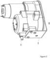
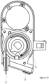
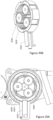
- an actuator 202 such as the actuator shown in Fig. 2
- the cable housing 236 may permanently or removaeably secure the exterior housing 142 of the control cable 140 while allowing an interior cable 144 to pass through into the interior of the actuator 202 and be attached to the pulley, as further described herein.
- the exterior housing 142 may cover some or all of the interior cable 144 from the mount 114 to the cable housing 236.
- the actuator may be mounted within the interior of the door 102 with a mounting bracket 250. In other embodiments the actuator may be mounted in proximate location to the vehicle door, whereby the control cable may be subjected to the pulling force by the actuator.
- the actuator 202 applies a force to the control cable 140, the force is applied to the interior cable 144, and is resisted by the mounting bracket 250. As such, the force of closing the door 102 is contained within the actuator 202, and little to no force is transmitted through the door 102.
- the actuator is configured to place the door check into the closed state by providing a pulling force on the control cable.
- the actuator is configured to convert a motor's rotational force into a linear force.
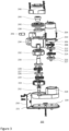
- the actuator 202 may include a motor 204 which provides a rotational force to sets of gears through multiple shafts. The gears may then provide an output rotational force to an output shaft.
- the motor may operate at 4000 rotations per minute (RPM), or more or less.
- the actuator may include a power train having multiple gear stages and a set of spur gears to transmit the rotation force provided by the motor 204 to the output shaft.
- the gear stages and set of spur gears may be positioned within one or more gearboxes, such as gear boxes 218 and 234.
- the output of the motor 204 may be connected to the first set of gears 208 that are connected to a second set of gears 214 via a first central gear 213.
- the second set of gears 214 may be connected to a first spur gear 220 via a first shaft 217.
- the gear ratio between the motor and the first set of gears may be 6:1, or more or less, and the gear ratio between the first set of gears and the second set of gears may be 6:1, or more or less.
- the power train may further include a second spur gear 221 to receive the rotational force generated by the first spur gear 220.
- the gear ratio between the first spur gear 220 and the second spur gear 221 may be 1:1, or more or less.
- the second spur gear 221 may then drive a third and fourth set of gears, 224 and 228, respectively, and subsequently the output shaft 230, as further shown in Figs. 3 and 4 .
- the second spur gear 221 may be connected to the third set of gears 224 via a pinion 252 which may include a third central gear to drive the third set of gears 224.
- the third set of gears 224 may be connected to a fourth set of gears 228 via a fourth central gear 227.
- the fourth set of gears 228 may be connected to the output shaft 230.
- the gear ratio between the second spur gear 221 and the third set of gears 224 may be 1:1, or more or less.
- the gear ratio between the third set of gears and the fourth set of gears may be 6:1, or more or less.
- the gear ratio between the fourth set of gears and the output shaft may be 6:1, or more or less.
- the output shaft may operate at 3 rotations per minute (RPM), or more or less.
- Each gear stage may be comprised of epicyclic gearing including a central gear, planet gears, and an outer ring gear.
- a first gear stage may include a first set of gears 208 (i.e., planet gears).
- the first set of gears 208 may be positioned on a carrier 212, which may have a first central gear 213 at its base.
- a ring gear (not shown), may be positioned within gear box 218 or at the bottom housing 210 of the motor 204.
- a motor shaft (not shown) may include a central gear 206 which, when the motor 204 is activated, may rotate in a first direction.
- the central gear may cause the first set of gears 208 to rotate in a second, opposite direction, around the ring gear.
- the rotations of the first set of gears 208 may cause the carrier 212 to rotate in the first direction, causing a first central gear 213 to also rotate in the first direction.
- four or more or fewer gear stages may be used.
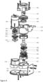
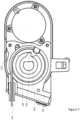
- the output shaft 230 may be connected to a hub.
- the hub 244 may be positioned within a pulley 240 and one or more springs 238.
- the hub 244, pulley 240, and one or more springs 238, may be enclosed within a housing 246.
- the output shaft 230 may be inserted into the hub 244, thereby enabling the actuator 202 to rotate the hub 244.
- the hub may include one or more exterior teeth.
- the hub 244 may include one or more teeth, such as tooth 544, which may rotate the pulley 240 by interlocking with one or more interior teeth, such as interior tooth 540 on the pulley 240.
- the second end of the interior cable 144, attached to the pulley at cable attachment point 510, may be pulled around the pulley, causing the interior cable 144 of the control cable to retract into the actuator. By doing such, a linear force may be applied on the door check 106 by the control cable 140, thereby causing the door to close.
- the second end interior cable 144 may be removeably or permanently attached to the pulley via a weld, nipple connection, knot, screw, eye fitting, clamp, adhesive, or other such connection.
- a drum or crank arm may be used in place of a pulley.
- the hub may stay in a reset position when the actuator is not in operation. For example, as shown in Fig. 5 , when in the reset position the tooth 544 of the hub 244 remains disengaged from the interior tooth 540 of the pulley. As such, no force is applied by the actuator 202 on the control cable 140 while in the reset position.
- the position of the pulley may be adjusted.
- the door check 106 may pull on the first end of the interior cable 140 which is connected to the connector 118.
- the control cable 140 may then rotate the pulley 240 as the connector 118 of the door check 106 provides a pulling force on the first end of the interior cable 144 thereby providing a pulling force on the pulley 240 at the cable attachment point 510.
- the interior cable 144 may be partially released from the interior of actuator 202 while the pulley 240 rotates into positions corresponding with the position of the door.
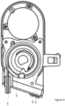
- the hub When the actuator is in operation the hub may rotate in a first direction to engage the pulley.
- the hub 244 may rotate in a first direction indicated by arrow 602.
- the tooth 544 of the hub 244 may engage with the interior tooth 540 of the pulley 240.
- the interior cable may retract into the actuator.
- the pulley 240 may rotate a corresponding distance, as can be seen between Fig. 5 , Fig. 6 and Fig. 7 .
- the pulley 240 may rotate the same angular distance as the hub 244, thereby causing the second end of the interior cable 144 to wrap around the pulley 240 as the connection point 510 is rotated with the pulley.
- linear force may be applied on the door check by the control cable.
- a pulling force is applied to the door check 106 by the first end of the interior cable 144 at the connector 118, as shown in Fig. 8 .
- the door check 106 is pulled through the intermediate states, toward the closed state. For example, as shown in Fig. 8 , the door check 106 is in an intermediate position associated with an intermediate position of the door.
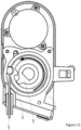
- the control cable causes the door check to close the door.
- the pulley 240 engaged with the hub 244, may cause the interior cable 144 to be rotated a predetermined distance around the pulley 240 in a first direction shown by arrow 602 in Fig. 9 .
- the predetermined distance may be 270 degrees or more or less.
- the force generated at the first end of the interior cable 144 on the door check 106, upon the second end of the interior cable 144 rotating the predetermined distance may be sufficient to place the door check into a closed state, as shown in Fig. 10 . As such, the door 102 will be forced into a closed position corresponding to the closed state.
- the hub may return to the reset position.
- the hub may rotate in a second direction opposite of the first direction until the hub returns to the reset position, as shown in Fig. 5 .
- the pulley may be connected to one or more springs 238, such as one or more clock springs, which hold the pulley 240 in place and maintain tension on the control cable 140 when the hub 244 returns to the reset position.
- the actuator and control cable may be configured to have very little effect on the force necessary to operate the door manually.
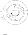
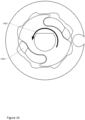
- the pulley may be connected to the one or more springs 238 which assist in unwrapping and wrapping the control cable around the pulley when the door is manually opened and closed, respectively, as shown in Figs. 11 and 12 .
- the first end of the interior cable 144 may be pulled by the door check 106, causing the second end of the interior cable 144 to rotate the pulley 240 in a second direction shown by arrow 1102, as shown in Fig. 11 .
- the one or more springs 238 may be placed under tension as the interior cable 144 unwinds from the actuator 240.
- the interior cable may be wrapped around the pulley when the door is manually closed.
- the door check 106 may move through intermediate states to the closed state, releasing tension from the first end of the causing the tension placed on the pulley 240 by the one or more springs 238 to cause the pulley 240 to rotate in the first direction shown by arrow 602, as shown in Fig. 12 .
- the one or more springs 238 may maintain tension on the pulley 240 while the pulley rotates and wraps the interior cable 144 around itself until the door reaches a closed position.
- the hub may be implemented as part of a ratchet.
- the ratchet hub 1302 may include one or more pawls 1306, which may be compared to hub 244 of Fig. 5 .
- the one or more pawls 1306 may be positioned in cutouts on the ratchet hub 1302.
- the one or more pawls 1306 may engage with one or more teeth 1308 on the ratchet pulley 1304, which may be compared to the pulley 240 in Fig. 3 , in response to a friction disc 1310 applying pressure to the one or more pawls 1306.
- a friction disc may cause the one or more pawls to expand into the one or more teeth on the ratchet pulley when the ratchet hub rotates.
- a friction disc 1310 may be pushed in a downward direction onto the ratchet hub 1302.
- the one or more pawls 1306 may be subjected to a friction force from the friction disc in a first direction 1502, thereby causing the one or more pawls 1306 to expand to an outwards position into the one or more teeth 1308, as shown in Fig. 15 .
- Fig. 14 a friction disc 1310 may be pushed in a downward direction onto the ratchet hub 1302.
- the one or more pawls 1306 may be subjected to a friction force from the friction disc in a first direction 1502, thereby causing the one or more pawls 1306 to expand to an outwards position into the one or more teeth 1308, as shown in Fig. 15 .
- the one or more pawls 1306 may be subjected to a second friction force shown by arrow 1602, in the opposite direction of the friction force in the first direction 1502, thereby causing the one or more pawls 1306 to retract into the cutouts on the ratchet hub 1302.
- the ratchet pulley 1304 may freely rotate in either direction when not subjected to the friction force by the friction pad.
- the ratchet hub may reset in any arbitrary position once the one or more pawls have retracted.
- the reset position of the ratchet hub may be only a few degrees, such as 5 degrees or more or less in a second direction reverse from first direction 1502.
- the door can be manually operated with a shorter reset delay than when the hub 244 is used.
- the one or more teeth 1308 arranged in a pattern around the ratchet pulley 1304 re-engagement and initiation of door closing can happen from any door position with potentially less delay for the one or more pawls 1306 on the ratchet hub to rotate into engagement with the one or more teeth 1308 on the pulley.
- a driving system 1710 in accordance with one aspect of the disclosure includes a vehicle 1701 with various components.
- the vehicle may have one or more computers, such as computer 1710 containing a processor 1720, memory 1730 and other components typically present in general purpose computers.
- the memory 1730 stores information accessible by processor 1720, including instructions 1732 and data 1734 that may be executed or otherwise used by the processor 1720.
- the memory 1730 may be of any type capable of storing information accessible by the processor, including a computer-readable medium, or other medium that stores data that may be read with the aid of an electronic device, such as a hard-drive, memory card, ROM, RAM, DVD or other optical disks, as well as other write-capable and read-only memories.
- Systems and methods may include different combinations of the foregoing, whereby different portions of the instructions and data are stored on different types of media.
- the instructions 1732 may be any set of instructions to be executed directly (such as machine code) or indirectly (such as scripts) by the processor.
- the instructions may be stored as computer code on the computer-readable medium.
- the terms "instructions” and “programs” may be used interchangeably herein.
- the instructions may be stored in object code format for direct processing by the processor, or in any other computer language including scripts or collections of independent source code modules that are interpreted on demand or compiled in advance. Functions, methods and routines of the instructions are explained in more detail below.
- the data 1734 may be retrieved, stored or modified by processor 1720 in accordance with the instructions 1732.
- the data may be stored in computer registers, in a relational database as a table having a plurality of different fields and records, XML documents or flat files.
- the data may also be formatted in any computer-readable format.
- image data may be stored as bitmaps comprised of grids of pixels that are stored in accordance with formats that are compressed or uncompressed, lossless (e.g., BMP) or lossy (e.g., JPEG), and bitmap or vector-based (e.g., SVG), as well as computer instructions for drawing graphics.
- the data may comprise any information sufficient to identify the relevant information, such as numbers, descriptive text, proprietary codes, references to data stored in other areas of the same memory or different memories (including other network locations) or information that is used by a function to calculate the relevant data.
- the processor 1720 may be any conventional processor, such as commercially available CPUs. Alternatively, the processor may be a dedicated device such as an ASIC or other hardware-based processor. Although Fig. 17 functionally illustrates the processor, memory, and other elements of computer 1710 as being within the same block, it will be understood by those of ordinary skill in the art that the processor, computer, or memory may actually comprise multiple processors, computers, or memories that may or may not be stored within the same physical housing. For example, memory may be a hard drive or other storage media located in a housing different from that of computer 1710. Accordingly, references to a processor or computer will be understood to include references to a collection of processors or computers or memories that may or may not operate in parallel. Rather than using a single processor to perform the steps described herein, some of the components, such as steering components and deceleration components, may each have their own processor that only performs calculations related to the component's specific function.
- the processor may be located remote from the vehicle and communicate with the vehicle wirelessly. In other aspects, some of the processes described herein are executed on a processor disposed within the vehicle and others by a remote processor, including taking the steps necessary to execute a single maneuver.
- Computer 1710 may all of the components normally used in connection with a computer such as a central processing unit (CPU), memory (e.g., RAM and internal hard drives) storing data 1734 and instructions such as a web browser, an electronic display 1742 (e.g., a monitor having a screen, a small LCD touch-screen or any other electrical device that is operable to display information), user input 1740 (e.g., a mouse, keyboard, touch screen and/or microphone), as well as various sensors (e.g., a video camera) for gathering explicit (e.g., a gesture) or implicit (e.g., "the person is asleep") information about the states and desires of a person.
- a computer such as a central processing unit (CPU), memory (e.g., RAM and internal hard drives) storing data 1734 and instructions such as a web browser, an electronic display 1742 (e.g., a monitor having a screen, a small LCD touch-screen or any other electrical device that is operable to display information), user input
- computer 1710 may be an autonomous driving computing system incorporated into vehicle 1701.
- the autonomous vehicle may include all of the features of a non-autonomous vehicle.
- the driving computing system may capable of communicating with various components of the vehicle.
- computer 1710 may be in communication with the vehicle's central processor 1760 and may send and receive information from the various systems of vehicle 1701, for example the braking 1780, acceleration 1782, signaling 1784, navigation 1786, and door assistance 1788 systems in order to control the movement, speed, collision management, general operation, etc. of vehicle 1701.
- Each of these systems may include one or more processors and/or a dedicated computer configured similarly to computer 1710 (with one or more processors and memory storing data and instructions).
- the door assistance system 1788 may manage the position of the doors on the vehicle, by controlling one or more actuators.
- computer 1710 may control some or all of these functions of vehicle 1701 and thus be fully or merely partially autonomous. It will be understood that although various systems and computer 1710 are shown within vehicle 1701, these elements may be external to vehicle 1701 or physically separated by large distances.
- the vehicle may also include a geographic position component 1744 in communication with computer 1710 for determining the geographic location of the device.
- the position component may include a GPS receiver to determine the device's latitude, longitude and/or altitude position.
- Other location systems such as laser-based localization systems, inertial-aided GPS, or camera-based localization may also be used to identify the location of the vehicle.
- the location of the vehicle may include an absolute geographical location, such as latitude, longitude, and altitude as well as relative location information, such as location relative to other cars immediately around it which can often be determined with less noise that absolute geographical location.
- the vehicle may also include other devices in communication with computer 1710, such as an accelerometer, gyroscope or another direction/speed detection device 546 to determine the direction and speed of the vehicle or changes thereto.
- acceleration device 1746 may determine its pitch, yaw or roll (or changes thereto) relative to the direction of gravity or a plane perpendicular thereto.
- the device may also track increases or decreases in speed and the direction of such changes.
- the device's provision of location and orientation data as set forth herein may be provided automatically to the user, computer 1710, other computers and combinations of the foregoing.
- the computer 1710 may control the direction and speed of the vehicle by controlling various components.
- computer 1710 may cause the vehicle to accelerate (e.g., by increasing fuel or other energy provided to the engine), decelerate (e.g., by decreasing the fuel supplied to the engine or by applying brakes) and change direction (e.g., by turning the front two wheels) based on detailed map information 1736 and input from the various components.
- the vehicle may also include an object detection component 1748, for detecting objects external and internal to the vehicle such as other vehicles, obstacles in the roadway, traffic signals, signs, trees, pedestrians, passengers etc.
- the detection system may include lasers, sonar, radar, cameras or any other detection devices which record data which may be processed by computer 1710.
- the vehicle is a small passenger vehicle, the car may include a laser mounted on the roof or other convenient location.
- Data from the plurality of sensors of the door assistance system 1788 may be received and processed by the computer 1710 and/or a dedicated computer of the door assistance system 1788 configured similarly to computer 1710 (with one or more processors and memory storing data and instructions), in real time in order to detect whether the door is open or closed. For instance, when the door assistance system 1788 detects that the door is open, a triggering signal may be sent to the actuator causing the actuator to close the door.
- a door entry sensor may determine whether a passenger or other foreign object is positioned between the door and the vehicle.
- a door entry sensor 2102 may determine through the sensor data, telematics and/or visual data (e.g., camera/video/lidar images, etc.) that a passenger or foreign object is detected. This sensor may be incorporated into the perception system and/or the plurality of sensors of the door assistance system such that this information is provided to the door assistance system 1788. When a passenger or foreign object is a detected the door entry sensor 2102 may prevent the door assistance system from triggering the actuator to close the door.
- the plurality of sensors may include a door angle sensor, as shown in Fig. 18 , and a motor angle sensor, as shown in Fig. 19 .
- the door angle sensor 1810 may track the position of the pulley by tracking a magnet 1820 positioned within a sensor ring on the pulley, as shown in Fig. 18 .
- the door assistance system 1788 may be able to determine the position of the door.
- a door sensor may be placed near the door check 106 to monitor the position of the door.
- the door sensor may provide further indication of the position of the door to verify the position determined by the door angle sensor.
- the motor angle sensor may determine the location of a magnet mounted to the output shaft.
- the motor angle sensor 1910 may track a magnet within the output shaft 1920 to determine the position of the hub, as shown in Fig. 19 .
- the door assistance system 1788 may be able to determine the amount of rotation needed by the hub to close the door or to return to the hub to the reset position.
- the door assistance system may be able to determine the speed and amount of power need to close the door based on the position of the hub.
- the door assistance system 1788 may send a control signal to the actuator 202 to control the closing of the door 102.
- the signal from the motor angle sensor 1910 may be used to infer the position of the door, eliminating or confirming the signal from the door angle sensor 1810.
- the motor drive current can be measured while the door is being closed in relation to the measured door angle.
- a current sensor may be used to detect the motor drive current while the door is being closed.
- the detected motor current may be used to determine if something is interfering with the normal door closing process. For example, if the detected current is greater than a predetermined value associated with a certain measured door angle, the door assistance system 1788 may determine that something is obstructing the closure of the door and terminate or reverse the door closing action.
- the detected current may be used with other information, such as the vehicle's orientation with respect to gravity, to adjust the predetermined value.
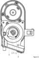
- the actuator may include an overload release to prevent excessive force from being transmitted to the control cable.
- a ring gear 2020 may be placed around one of the gear sets 2030, such as the third gear set.
- the exterior of the ring gear may include a plurality of notches 2040 in which a tapered pawl 2010 may be positioned.
- the tapered pawl 2010 may be released from one of the one or more notches 2040 allowing the ring gear to rotate in an opposite direction of the gear set.
- a spring attached to the tapered pawl 2010 may push the tapered pawl into one of the one or more notches 2040, thereby allowing the gear set to rotate.
- the tapered pawl acts as an overload release.
- the door assistance system may send a triggering signal to the actuator.
- the triggering signal may cause the actuator, such as actuator 202, to activate and close the door.
- sensors such as cameras, lidar, radar, etc., may be used to determine if a passenger or object has entered or exited the vehicle. Upon determining that a passenger or object has entered or exited the vehicle, the amount of time the door is left open may be reset to zero.
- data from the plurality of sensors of the door assistance system may be used to assist in closing the door.
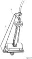
- a sensor such as door entry sensor 2102
- the door entry sensor 2102 may provide a signal to the door assistance system 1788 (not shown), indicating that the door 102 of the vehicle 2100 is in an open position.
- the door assistance system 1788 may send a triggering signal to the actuator 202, mounted in the interior of the door 102.
- the actuator 202 may pull cable 140, which in turn pulls the door check 106, closing the door 102, as shown in Fig. 21B .
- the triggering signal to close the door may come from a source external to the door assistance system.
- a remote triggering signal may be generated "manually" by a button, or other input, that a user, such as a driver or passenger of the vehicle may press.
- the remote triggering signal may then cause the door assistance system to trigger the actuator, or the remote triggering signal may directly trigger the actuator.
- a voice command or visual command may generate the remote triggering signal.
- the triggering may also come remotely, such as from an individual, such as a dispatcher, or remote computer, as an over-the-air command. In this regard, a remote individual or computer may monitor the data from the vehicles sensors and determine that a door was left open.
- the remote individual or computer may determine through the sensor data, telematics and/or visual data (e.g., camera/video/lidar images, etc.) that a door on the vehicle was left open. As such, the remote individual or computer may determine that it is safe to close the door based on a precise understanding of who's in and around the car, and when it's safe, rather than basing the actuation solely on a timer.
- telematics and/or visual data e.g., camera/video/lidar images, etc.
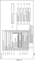
- Flow diagram 2200 of Fig. 22 is an example of some of the aspects described above which may be performed by the door assistance system 1788.
- the door assistance system 1788 may receive, from one or more sensors, information indicating that a door on a vehicle is not closed, as shown in block 2201.
- the door assistance system 1788 may determine to send a triggering signal to close the door, as shown in block 2202.
- the door assistance system 1788 may send the triggering signal to an actuator and, in response to receiving the triggering signal, the actuator to close the door of the vehicle, as shown in block 2203.
Landscapes
- Engineering & Computer Science (AREA)
- Mechanical Engineering (AREA)
- Power-Operated Mechanisms For Wings (AREA)
Claims (14)
- System zum automatischen Schließen einer Tür (102) eines Fahrzeugs (120), umfassend:einen Türfeststeller (106), der zwischen einer Karosserie des Fahrzeugs und der Tür des Fahrzeugs angeschlossen ist; ein Drahtseil (140); undeinen Aktuator (202), der einen Motor (204) und eine Riemenscheibe (240) umfasst,wobei ein erstes Ende des Drahtseils an dem Türfeststeller befestigt ist und ein zweites Ende des Drahtseils an der Riemenscheibe befestigt ist, und wobei der Motor so konfiguriert ist, dass er das zweite Ende des Drahtseils derart um die Riemenscheibe zieht, dass das erste Ende des Drahtseils veranlasst, dass der Türfeststeller in einen Schließzustand versetzt wird, wobei der Schließzustand einer Schließstellung der Tür des Fahrzeugs entspricht.
- System nach Anspruch 1, wobei ein oder mehrere Türwinkelsensoren eine Position der Riemenscheibe überwachen, indem sie eine Position eines Magneten der Riemenscheibe verfolgen, und Informationen senden, die angeben, dass die Tür nicht geschlossen ist, wenn die Position der Riemenscheibe mit einer Tür-offen-Stellung assoziiert ist.
- System nach Anspruch 1, wobei das erste Ende des Drahtseils an einem Verbindungsstück (118) an dem Türfeststeller befestigt ist.
- System nach Anspruch 1, wobei das Drahtseil ein Bowdenzug ist, der ein Außengehäuse (142) und ein innenliegendes Drahtseil (144) umfasst.
- System nach Anspruch 4, wobei der Türfeststeller ferner eine Halterung (114) beinhaltet und der Aktuator ferner ein Drahtseilgehäuse (236) beinhaltet.
- System nach Anspruch 4, wobei ein erstes Ende des innenliegenden Drahtseils an einem Verbindungsstück an dem Türfeststeller befestigt ist und ein zweites Ende des innenliegenden Drahtseils an der Riemenscheibe befestigt ist.
- System nach Anspruch 5, wobei ein erstes Ende des Außengehäuses an der Halterung befestigt ist und das zweite Ende des Außengehäuses an dem Drahtseilgehäuse befestigt ist.
- System nach Anspruch 1, wobei die Riemenscheibe einen oder mehrere Innenzähne (540) beinhaltet.
- System nach Anspruch 8, wobei der Aktuator ferner eine Nabe (244) umfasst, und wobei die Nabe einen oder mehrere Zähne (544) beinhaltet.
- System nach Anspruch 9, wobei der Aktuator ferner eine Abtriebswelle (230) umfasst, die mit der Nabe verbunden ist; und
wobei der Motor so konfiguriert ist, dass er das zweite Ende des Drahtseils derart um die Riemenscheibe zieht, dass das erste Ende des Drahtseils veranlasst, dass der Türfeststeller in einen Schließzustand versetzt wird, indem die Abtriebswelle so gedreht wird, dass die Abtriebswelle die Nabe dreht, und der eine oder die mehreren Zähne der Nabe mit dem einen oder den mehreren Innenzähnen der Riemenscheibe in Eingriff kommen, wodurch die Riemenscheibe veranlasst wird, sich zu drehen. - System nach Anspruch 1, wobei der Motor so konfiguriert ist, dass er das zweite Ende des Drahtseils derart um die Riemenscheibe zieht, dass das erste Ende des Drahtseils veranlasst, dass der Türfeststeller in einen Schließzustand versetzt wird, wenn ein Auslösesignal empfangen wird.
- System nach Anspruch 10, ferner umfassend einen oder mehrere Türwinkelsensoren zum Überwachen der Position der Riemenscheibe, und/oder ferner umfassend einen oder mehrere Motorwinkelsensoren zum Überwachen der Position der Abtriebswelle.
- System nach Anspruch 1, wobei der Aktuator ferner eine Nabe und eine Reibscheibe umfasst, wobeidie Nabe eine oder mehrere Sperrklinken (1306) beinhaltet; und die Riemenscheibe einen oder mehrere Zähne (1308) beinhaltet,wobei der Motor so konfiguriert ist, dass er das zweite Ende des Drahtseils derart um die Riemenscheibe zieht, dass das erste Ende des Drahtseils veranlasst, dass der Türfeststeller in einen Schließzustand versetzt wird, indem die Abtriebswelle so gedreht wird, dass die Abtriebswelle die Nabe in einer ersten Richtung dreht, und der eine oder die mehreren Zähne der Nabe mit dem einen oder den mehreren Innenzähnen der Riemenscheibe in Eingriff kommen, wodurch die Riemenscheibe veranlasst wird, sich zu drehen.
- System nach Anspruch 13, wobei der Aktuator so konfiguriert ist, dass er die eine oder die mehreren Sperrklinken der Nabe in den einen oder die mehreren Zähne der Riemenscheibe einklinkt, wenn die Reibscheibe eine nach unten gerichtete Kraft auf die eine oder die mehreren Sperrklinken der Nabe ausübt, während die Abtriebswelle die Nabe in der ersten Richtung dreht, und die eine oder die mehreren Sperrklinken der Nabe ausklinkt, wenn die Reibscheibe eine nach unten gerichtete Kraft auf die eine oder die mehreren Sperrklinken ausübt, während die Abtriebswelle die Nabe in der zweiten Richtung dreht.
Applications Claiming Priority (2)
| Application Number | Priority Date | Filing Date | Title |
|---|---|---|---|
| US15/054,811 US9879463B2 (en) | 2016-02-26 | 2016-02-26 | Device and method for powered closing of car doors |
| PCT/US2017/018886 WO2017147156A1 (en) | 2016-02-26 | 2017-02-22 | Device and method for powered closing of car doors |
Publications (3)
| Publication Number | Publication Date |
|---|---|
| EP3420171A1 EP3420171A1 (de) | 2019-01-02 |
| EP3420171A4 EP3420171A4 (de) | 2020-02-12 |
| EP3420171B1 true EP3420171B1 (de) | 2024-05-22 |
Family
ID=59679431
Family Applications (1)
| Application Number | Title | Priority Date | Filing Date |
|---|---|---|---|
| EP17757126.2A Active EP3420171B1 (de) | 2016-02-26 | 2017-02-22 | Vorrichtung zum elektrischen schliessen von autotüren |
Country Status (6)
| Country | Link |
|---|---|
| US (2) | US9879463B2 (de) |
| EP (1) | EP3420171B1 (de) |
| JP (2) | JP6751768B2 (de) |
| KR (1) | KR102102298B1 (de) |
| CN (1) | CN108699884B (de) |
| WO (1) | WO2017147156A1 (de) |
Families Citing this family (21)
| Publication number | Priority date | Publication date | Assignee | Title |
|---|---|---|---|---|
| JP6211506B2 (ja) * | 2014-12-03 | 2017-10-11 | アイシン精機株式会社 | 車両用開閉体の開閉検知装置 |
| US10611490B2 (en) * | 2016-11-02 | 2020-04-07 | Rohr, Inc. | Fan cowl fairing restraining system |
| CN106761136B (zh) * | 2016-12-27 | 2018-04-20 | 青岛海尔股份有限公司 | 自动开门装置及具有该装置的冰箱 |
| US10344519B2 (en) * | 2017-04-11 | 2019-07-09 | Ford Global Technologies Llc | Vehicle power door system |
| DE102017115183A1 (de) * | 2017-07-06 | 2019-01-10 | Edscha Engineering Gmbh | Antriebsvorrichtung für eine Fahrzeugklappe |
| US10465430B2 (en) | 2017-07-20 | 2019-11-05 | Brose Fahrzeugteile Gmbh & Co. Kommanditgesellschaft, Bamberg | Drive device for a vehicle door |
| GB2565794A (en) * | 2017-08-22 | 2019-02-27 | Brose Fahrzeugteile Gmbh & Co Kg | Drive device for a vehicle door |
| US10774574B2 (en) * | 2018-03-26 | 2020-09-15 | Honda Motor Co., Ltd. | Operation of vehicle power doors |
| CN109281568A (zh) * | 2018-12-05 | 2019-01-29 | 广东东箭汽车科技股份有限公司 | 螺母丝杠式自动门开闭机构、汽车自动门和汽车 |
| DE102018132666A1 (de) * | 2018-12-18 | 2020-06-18 | Kiekert Aktiengesellschaft | Aufstellvorrichtung für ein kraftfahrzeugtürelement |
| JP2020111134A (ja) * | 2019-01-10 | 2020-07-27 | アイシン精機株式会社 | 車両用ドア装置 |
| DE102019101514A1 (de) * | 2019-01-22 | 2020-07-23 | Bayerische Motoren Werke Aktiengesellschaft | Steuereinheit und Verfahren zum Betrieb einer automatischen Klappe und/oder Tür |
| US11492835B2 (en) * | 2019-07-05 | 2022-11-08 | Toyota Research Institute, Inc. | Autonomous control of vehicle cargo area doors |
| US11814889B2 (en) * | 2020-03-27 | 2023-11-14 | AISIN Technical Center of America, Inc. | Systems and methods for operating a power tailgate system |
| CN111441688A (zh) * | 2020-05-12 | 2020-07-24 | 谢朋朋 | 基于汽车侧门的电动开关机构及其构成的汽车电动门 |
| CN111691781A (zh) * | 2020-07-20 | 2020-09-22 | 谢朋朋 | 一种伸拉机构 |
| DE102022103328A1 (de) * | 2021-02-22 | 2022-08-25 | Magna Closures Inc. | Verteiltes steuerungssystem für servogesteuerten türantrieb |
| JP7726449B2 (ja) * | 2021-10-15 | 2025-08-20 | 三井金属アクト株式会社 | ドア開閉装置 |
| JP7687558B2 (ja) * | 2021-10-22 | 2025-06-03 | 三井金属アクト株式会社 | 車両用開閉体駆動装置 |
| US12035868B2 (en) * | 2022-04-14 | 2024-07-16 | Haier Us Appliance Solutions, Inc. | Systems for prevention of accidental control inputs in appliances |
| US12146353B2 (en) * | 2022-08-15 | 2024-11-19 | GM Global Technology Operations LLC | Secure stop adjustable door opening limiter |
Family Cites Families (37)
| Publication number | Priority date | Publication date | Assignee | Title |
|---|---|---|---|---|
| FR2222852A5 (de) * | 1973-03-20 | 1974-10-18 | Peugeot & Renault | |
| US4823059A (en) * | 1988-01-14 | 1989-04-18 | General Motors Corporation | Control apparatus for a compartment panel pull down mechanism |
| US4850140A (en) * | 1988-08-25 | 1989-07-25 | General Motors Corporation | Releasable connector for closure operating mechanism |
| US5361612A (en) * | 1993-02-11 | 1994-11-08 | Winner International | Hood lock with reel and cable |
| US5434487A (en) | 1993-05-20 | 1995-07-18 | General Motors Corporation | Vehicle door manual to power move |
| US5531498A (en) * | 1994-12-01 | 1996-07-02 | Chrysler Corporation | Vehicle body with powered lift type tailgate |
| JP3314681B2 (ja) * | 1996-09-26 | 2002-08-12 | トヨタ車体株式会社 | 跳ね上げ式車両ドアの自動閉鎖装置 |
| US6126222A (en) * | 1998-05-06 | 2000-10-03 | Ford Global Technologies, Inc. | Liftgate assembly |
| EP1468160A1 (de) * | 2002-01-24 | 2004-10-20 | Intier Automotive Closures Inc. | Antriebsvorrichtung einer motorbetätigten heckklappe und systemsteuerungsverfahren |
| WO2004018809A1 (de) * | 2002-08-23 | 2004-03-04 | Daimlerchrysler Ag | Vorrichtung zum schliessen einer tür eines kraftfahrzeuges |
| EP1530666A1 (de) | 2002-08-23 | 2005-05-18 | DaimlerChrysler AG | Kraftfahrzeug mit einer vorrichtung zur steuerung der verstellbewegung eines schliessteiles |
| US6918210B1 (en) * | 2003-02-20 | 2005-07-19 | Edward D. Smiley | Cable driven sliding door actuator |
| DE10318674B8 (de) * | 2003-04-24 | 2006-04-13 | Stabilus Gmbh | Betätigungseinrichtung |
| WO2005049947A1 (en) * | 2003-11-20 | 2005-06-02 | Intier Automotive Closures Inc. | System for power closing of a self rising closure panel |
| DE102004004957A1 (de) * | 2004-01-08 | 2005-08-04 | Valeo Sicherheitssysteme Gmbh | Vorrichtung zum automatischen Schließen der Heckklappe eines Kraftfahrzeuges |
| WO2005066441A1 (de) * | 2004-01-08 | 2005-07-21 | Valeo Securite Habitacle (Sas) | Vorrichtung zum automatischen schliessen der heckklappe eines kraftfahrzeuges |
| DE102005061610A1 (de) | 2005-12-21 | 2007-07-05 | Brose Fahrzeugteile Gmbh & Co. Kommanditgesellschaft, Coburg | Verfahren und Vorrichtung zum Steuern der Schließbewegung eines Karosseriebauteils für Fahrzeuge |
| JP4809106B2 (ja) * | 2006-04-14 | 2011-11-09 | アスモ株式会社 | 開閉装置 |
| JP2007308929A (ja) * | 2006-05-17 | 2007-11-29 | Aisin Seiki Co Ltd | 車両ドア開閉制御装置 |
| US7600345B2 (en) * | 2006-05-25 | 2009-10-13 | Marlene Rene Slopack | Swing door operating system |
| JP4389897B2 (ja) | 2006-05-30 | 2009-12-24 | 三菱自動車工業株式会社 | 自動車用ドアの開動作規制装置 |
| JP2008057157A (ja) * | 2006-08-30 | 2008-03-13 | Aisin Seiki Co Ltd | 移動体の制御装置 |
| US7770959B2 (en) * | 2006-10-30 | 2010-08-10 | Gm Global Technology Operations, Inc. | Door actuation systems using active materials |
| US7686378B2 (en) * | 2007-06-01 | 2010-03-30 | Gm Global Technology Operations, Inc. | Power swinging side door system and method |
| JP5381117B2 (ja) * | 2009-01-21 | 2014-01-08 | 株式会社ジェイテクト | 電気式動力舵取装置 |
| US8755975B2 (en) * | 2011-01-06 | 2014-06-17 | Honda Motor Co., Ltd. | Automatic vehicle door movement control system |
| JP5382050B2 (ja) * | 2011-04-06 | 2014-01-08 | アイシン精機株式会社 | 車両用開閉体作動装置 |
| JP6114946B2 (ja) | 2012-06-19 | 2017-04-19 | 三井金属アクト株式会社 | 車両用ドアの開閉駆動装置 |
| JP2014136879A (ja) * | 2013-01-15 | 2014-07-28 | Auto Network Gijutsu Kenkyusho:Kk | ドア開閉装置 |
| WO2015061885A1 (en) | 2013-10-29 | 2015-05-07 | Magna Closures Inc. | Closure panel drive mechanism with associated linear actuator |
| US10337216B2 (en) * | 2014-01-02 | 2019-07-02 | Strattec Power Access Llc | Vehicle door |
| US9834978B2 (en) * | 2014-04-04 | 2017-12-05 | Ford Global Technologies, Llc | Power door system for a motor vehicle |
| JP2015218466A (ja) * | 2014-05-15 | 2015-12-07 | 三井金属アクト株式会社 | ドア開閉装置およびドア開閉方法 |
| US9566912B2 (en) * | 2014-06-11 | 2017-02-14 | Ford Global Technologies, Llc | Automatic closing arrangement for vehicle stowage compartments |
| JP6312138B2 (ja) | 2014-07-28 | 2018-04-18 | オムロンオートモーティブエレクトロニクス株式会社 | 扉開閉制御装置 |
| US9890576B2 (en) * | 2015-07-29 | 2018-02-13 | Ford Global Technologies, Llc | Active door operation based on voice commands |
| US10030431B2 (en) * | 2015-07-29 | 2018-07-24 | Ford Global Technologies, Llc | Automotive door power assist |
-
2016
- 2016-02-26 US US15/054,811 patent/US9879463B2/en active Active
-
2017
- 2017-02-22 KR KR1020187024488A patent/KR102102298B1/ko not_active Expired - Fee Related
- 2017-02-22 WO PCT/US2017/018886 patent/WO2017147156A1/en not_active Ceased
- 2017-02-22 JP JP2018542748A patent/JP6751768B2/ja not_active Expired - Fee Related
- 2017-02-22 CN CN201780012528.2A patent/CN108699884B/zh active Active
- 2017-02-22 EP EP17757126.2A patent/EP3420171B1/de active Active
- 2017-11-21 US US15/819,350 patent/US10544616B2/en active Active
-
2020
- 2020-08-17 JP JP2020137469A patent/JP7054723B2/ja not_active Expired - Fee Related
Also Published As
| Publication number | Publication date |
|---|---|
| KR102102298B1 (ko) | 2020-04-21 |
| EP3420171A4 (de) | 2020-02-12 |
| US20170247929A1 (en) | 2017-08-31 |
| US10544616B2 (en) | 2020-01-28 |
| EP3420171A1 (de) | 2019-01-02 |
| JP6751768B2 (ja) | 2020-09-09 |
| JP7054723B2 (ja) | 2022-04-14 |
| WO2017147156A1 (en) | 2017-08-31 |
| JP2020193559A (ja) | 2020-12-03 |
| CN108699884A (zh) | 2018-10-23 |
| KR20180098425A (ko) | 2018-09-03 |
| CN108699884B (zh) | 2021-03-23 |
| US9879463B2 (en) | 2018-01-30 |
| JP2019511650A (ja) | 2019-04-25 |
| US20180142511A1 (en) | 2018-05-24 |
Similar Documents
| Publication | Publication Date | Title |
|---|---|---|
| EP3420171B1 (de) | Vorrichtung zum elektrischen schliessen von autotüren | |
| US11142175B2 (en) | Brake supplement assist control | |
| EP3848264B1 (de) | Fernverifizierung der anzahl der passagiere in einem autonomen fahrzeug | |
| US9315178B1 (en) | Model checking for autonomous vehicles | |
| US5430432A (en) | Automotive warning and recording system | |
| EP3558779B1 (de) | Fahrzeugsteuerungen auf basis des gemessenen frachtgewichts | |
| US20190163186A1 (en) | Autonomous vehicle and method of controlling the same | |
| CN102858606B (zh) | 用于防止不受监管的车辆运动的方法和系统 | |
| US12202457B2 (en) | Supplemental braking control system in autonomous vehicles | |
| CN105774794A (zh) | 汽车行驶安全装置 | |
| CN109455136A (zh) | 停车警示装置、车辆及车辆停车警示方法 | |
| WO2018205375A1 (zh) | 车辆控制方法及装置 | |
| US9221434B2 (en) | Method for operating a self-propelled agricultural machine | |
| US12510890B2 (en) | Remote assistance for autonomous vehicles in predetermined situations | |
| US12257991B2 (en) | Automated braking control systems | |
| US20240416875A1 (en) | Vehicle Guidance System and Method for Controlling an Emergency Stop Assistance Function of a Motor Vehicle | |
| CN116872883A (zh) | 车辆后排安全带提示方法、装置、车辆及可读存储介质 | |
| CN109839923A (zh) | 汽车控制 | |
| JP7476661B2 (ja) | 車両の周辺監視システム | |
| US20260035097A1 (en) | Vehicle for towing aircraft | |
| US20260014974A1 (en) | Automatic coordinated control of vehicle and winch | |
| JP2024165313A (ja) | 車両の制御装置 | |
| JP2012018654A (ja) | 車、車両の自動運転システム |
Legal Events
| Date | Code | Title | Description |
|---|---|---|---|
| STAA | Information on the status of an ep patent application or granted ep patent |
Free format text: STATUS: THE INTERNATIONAL PUBLICATION HAS BEEN MADE |
|
| PUAI | Public reference made under article 153(3) epc to a published international application that has entered the european phase |
Free format text: ORIGINAL CODE: 0009012 |
|
| STAA | Information on the status of an ep patent application or granted ep patent |
Free format text: STATUS: REQUEST FOR EXAMINATION WAS MADE |
|
| 17P | Request for examination filed |
Effective date: 20180808 |
|
| AK | Designated contracting states |
Kind code of ref document: A1 Designated state(s): AL AT BE BG CH CY CZ DE DK EE ES FI FR GB GR HR HU IE IS IT LI LT LU LV MC MK MT NL NO PL PT RO RS SE SI SK SM TR |
|
| AX | Request for extension of the european patent |
Extension state: BA ME |
|
| DAV | Request for validation of the european patent (deleted) | ||
| DAX | Request for extension of the european patent (deleted) | ||
| RIC1 | Information provided on ipc code assigned before grant |
Ipc: E05F 15/603 20150101ALI20190924BHEP Ipc: E05C 17/20 20060101ALI20190924BHEP Ipc: E05F 15/63 20150101ALI20190924BHEP Ipc: E05F 15/79 20150101ALI20190924BHEP Ipc: E05F 15/627 20150101ALI20190924BHEP Ipc: E05F 15/70 20150101AFI20190924BHEP |
|
| A4 | Supplementary search report drawn up and despatched |
Effective date: 20200114 |
|
| RIC1 | Information provided on ipc code assigned before grant |
Ipc: E05F 15/63 20150101ALI20200108BHEP Ipc: E05F 15/603 20150101ALI20200108BHEP Ipc: E05F 15/79 20150101ALI20200108BHEP Ipc: E05F 15/627 20150101ALI20200108BHEP Ipc: E05C 17/20 20060101ALI20200108BHEP Ipc: E05F 15/70 20150101AFI20200108BHEP |
|
| REG | Reference to a national code |
Ref country code: DE Ref legal event code: R079 Free format text: PREVIOUS MAIN CLASS: E05F0015700000 Ipc: E05F0015627000 Ref country code: DE Ref legal event code: R079 Ref document number: 602017082109 Country of ref document: DE Free format text: PREVIOUS MAIN CLASS: E05F0015700000 Ipc: E05F0015627000 |
|
| RIC1 | Information provided on ipc code assigned before grant |
Ipc: E05F 15/63 20150101ALI20230512BHEP Ipc: E05C 17/20 20060101ALI20230512BHEP Ipc: E05F 15/79 20150101ALI20230512BHEP Ipc: E05F 15/70 20150101ALI20230512BHEP Ipc: E05B 79/20 20140101ALI20230512BHEP Ipc: E05B 81/38 20140101ALI20230512BHEP Ipc: E05B 81/64 20140101ALI20230512BHEP Ipc: E05B 81/70 20140101ALI20230512BHEP Ipc: E05F 15/627 20150101AFI20230512BHEP |
|
| GRAP | Despatch of communication of intention to grant a patent |
Free format text: ORIGINAL CODE: EPIDOSNIGR1 |
|
| STAA | Information on the status of an ep patent application or granted ep patent |
Free format text: STATUS: GRANT OF PATENT IS INTENDED |
|
| INTG | Intention to grant announced |
Effective date: 20230719 |
|
| GRAJ | Information related to disapproval of communication of intention to grant by the applicant or resumption of examination proceedings by the epo deleted |
Free format text: ORIGINAL CODE: EPIDOSDIGR1 |
|
| STAA | Information on the status of an ep patent application or granted ep patent |
Free format text: STATUS: REQUEST FOR EXAMINATION WAS MADE |
|
| GRAP | Despatch of communication of intention to grant a patent |
Free format text: ORIGINAL CODE: EPIDOSNIGR1 |
|
| INTC | Intention to grant announced (deleted) | ||
| RIN1 | Information on inventor provided before grant (corrected) |
Inventor name: ELLIS, ROBERT JOHN Inventor name: WARBURTON, ANDREW PAUL Inventor name: LOMBROZO, PETER CRAIG |
|
| STAA | Information on the status of an ep patent application or granted ep patent |
Free format text: STATUS: GRANT OF PATENT IS INTENDED |
|
| INTG | Intention to grant announced |
Effective date: 20231221 |
|
| GRAS | Grant fee paid |
Free format text: ORIGINAL CODE: EPIDOSNIGR3 |
|
| GRAA | (expected) grant |
Free format text: ORIGINAL CODE: 0009210 |
|
| STAA | Information on the status of an ep patent application or granted ep patent |
Free format text: STATUS: THE PATENT HAS BEEN GRANTED |
|
| AK | Designated contracting states |
Kind code of ref document: B1 Designated state(s): AL AT BE BG CH CY CZ DE DK EE ES FI FR GB GR HR HU IE IS IT LI LT LU LV MC MK MT NL NO PL PT RO RS SE SI SK SM TR |
|
| P01 | Opt-out of the competence of the unified patent court (upc) registered |
Effective date: 20240417 |
|
| REG | Reference to a national code |
Ref country code: GB Ref legal event code: FG4D |
|
| REG | Reference to a national code |
Ref country code: CH Ref legal event code: EP |
|
| REG | Reference to a national code |
Ref country code: DE Ref legal event code: R096 Ref document number: 602017082109 Country of ref document: DE |
|
| REG | Reference to a national code |
Ref country code: IE Ref legal event code: FG4D |
|
| REG | Reference to a national code |
Ref country code: LT Ref legal event code: MG9D |
|
| REG | Reference to a national code |
Ref country code: NL Ref legal event code: MP Effective date: 20240522 |
|
| PG25 | Lapsed in a contracting state [announced via postgrant information from national office to epo] |
Ref country code: IS Free format text: LAPSE BECAUSE OF FAILURE TO SUBMIT A TRANSLATION OF THE DESCRIPTION OR TO PAY THE FEE WITHIN THE PRESCRIBED TIME-LIMIT Effective date: 20240922 |
|
| PG25 | Lapsed in a contracting state [announced via postgrant information from national office to epo] |
Ref country code: BG Free format text: LAPSE BECAUSE OF FAILURE TO SUBMIT A TRANSLATION OF THE DESCRIPTION OR TO PAY THE FEE WITHIN THE PRESCRIBED TIME-LIMIT Effective date: 20240522 |
|
| PG25 | Lapsed in a contracting state [announced via postgrant information from national office to epo] |
Ref country code: HR Free format text: LAPSE BECAUSE OF FAILURE TO SUBMIT A TRANSLATION OF THE DESCRIPTION OR TO PAY THE FEE WITHIN THE PRESCRIBED TIME-LIMIT Effective date: 20240522 Ref country code: FI Free format text: LAPSE BECAUSE OF FAILURE TO SUBMIT A TRANSLATION OF THE DESCRIPTION OR TO PAY THE FEE WITHIN THE PRESCRIBED TIME-LIMIT Effective date: 20240522 |
|
| PG25 | Lapsed in a contracting state [announced via postgrant information from national office to epo] |
Ref country code: GR Free format text: LAPSE BECAUSE OF FAILURE TO SUBMIT A TRANSLATION OF THE DESCRIPTION OR TO PAY THE FEE WITHIN THE PRESCRIBED TIME-LIMIT Effective date: 20240823 |
|
| PG25 | Lapsed in a contracting state [announced via postgrant information from national office to epo] |
Ref country code: PT Free format text: LAPSE BECAUSE OF FAILURE TO SUBMIT A TRANSLATION OF THE DESCRIPTION OR TO PAY THE FEE WITHIN THE PRESCRIBED TIME-LIMIT Effective date: 20240923 |
|
| REG | Reference to a national code |
Ref country code: AT Ref legal event code: MK05 Ref document number: 1688905 Country of ref document: AT Kind code of ref document: T Effective date: 20240522 |
|
| PG25 | Lapsed in a contracting state [announced via postgrant information from national office to epo] |
Ref country code: NL Free format text: LAPSE BECAUSE OF FAILURE TO SUBMIT A TRANSLATION OF THE DESCRIPTION OR TO PAY THE FEE WITHIN THE PRESCRIBED TIME-LIMIT Effective date: 20240522 |
|
| PG25 | Lapsed in a contracting state [announced via postgrant information from national office to epo] |
Ref country code: ES Free format text: LAPSE BECAUSE OF FAILURE TO SUBMIT A TRANSLATION OF THE DESCRIPTION OR TO PAY THE FEE WITHIN THE PRESCRIBED TIME-LIMIT Effective date: 20240522 |
|
| PG25 | Lapsed in a contracting state [announced via postgrant information from national office to epo] |
Ref country code: AT Free format text: LAPSE BECAUSE OF FAILURE TO SUBMIT A TRANSLATION OF THE DESCRIPTION OR TO PAY THE FEE WITHIN THE PRESCRIBED TIME-LIMIT Effective date: 20240522 |
|
| PG25 | Lapsed in a contracting state [announced via postgrant information from national office to epo] |
Ref country code: PL Free format text: LAPSE BECAUSE OF FAILURE TO SUBMIT A TRANSLATION OF THE DESCRIPTION OR TO PAY THE FEE WITHIN THE PRESCRIBED TIME-LIMIT Effective date: 20240522 |
|
| PG25 | Lapsed in a contracting state [announced via postgrant information from national office to epo] |
Ref country code: LV Free format text: LAPSE BECAUSE OF FAILURE TO SUBMIT A TRANSLATION OF THE DESCRIPTION OR TO PAY THE FEE WITHIN THE PRESCRIBED TIME-LIMIT Effective date: 20240522 |
|
| PG25 | Lapsed in a contracting state [announced via postgrant information from national office to epo] |
Ref country code: PT Free format text: LAPSE BECAUSE OF FAILURE TO SUBMIT A TRANSLATION OF THE DESCRIPTION OR TO PAY THE FEE WITHIN THE PRESCRIBED TIME-LIMIT Effective date: 20240923 Ref country code: PL Free format text: LAPSE BECAUSE OF FAILURE TO SUBMIT A TRANSLATION OF THE DESCRIPTION OR TO PAY THE FEE WITHIN THE PRESCRIBED TIME-LIMIT Effective date: 20240522 Ref country code: NO Free format text: LAPSE BECAUSE OF FAILURE TO SUBMIT A TRANSLATION OF THE DESCRIPTION OR TO PAY THE FEE WITHIN THE PRESCRIBED TIME-LIMIT Effective date: 20240822 Ref country code: NL Free format text: LAPSE BECAUSE OF FAILURE TO SUBMIT A TRANSLATION OF THE DESCRIPTION OR TO PAY THE FEE WITHIN THE PRESCRIBED TIME-LIMIT Effective date: 20240522 Ref country code: LV Free format text: LAPSE BECAUSE OF FAILURE TO SUBMIT A TRANSLATION OF THE DESCRIPTION OR TO PAY THE FEE WITHIN THE PRESCRIBED TIME-LIMIT Effective date: 20240522 Ref country code: IS Free format text: LAPSE BECAUSE OF FAILURE TO SUBMIT A TRANSLATION OF THE DESCRIPTION OR TO PAY THE FEE WITHIN THE PRESCRIBED TIME-LIMIT Effective date: 20240922 Ref country code: HR Free format text: LAPSE BECAUSE OF FAILURE TO SUBMIT A TRANSLATION OF THE DESCRIPTION OR TO PAY THE FEE WITHIN THE PRESCRIBED TIME-LIMIT Effective date: 20240522 Ref country code: GR Free format text: LAPSE BECAUSE OF FAILURE TO SUBMIT A TRANSLATION OF THE DESCRIPTION OR TO PAY THE FEE WITHIN THE PRESCRIBED TIME-LIMIT Effective date: 20240823 Ref country code: FI Free format text: LAPSE BECAUSE OF FAILURE TO SUBMIT A TRANSLATION OF THE DESCRIPTION OR TO PAY THE FEE WITHIN THE PRESCRIBED TIME-LIMIT Effective date: 20240522 Ref country code: ES Free format text: LAPSE BECAUSE OF FAILURE TO SUBMIT A TRANSLATION OF THE DESCRIPTION OR TO PAY THE FEE WITHIN THE PRESCRIBED TIME-LIMIT Effective date: 20240522 Ref country code: BG Free format text: LAPSE BECAUSE OF FAILURE TO SUBMIT A TRANSLATION OF THE DESCRIPTION OR TO PAY THE FEE WITHIN THE PRESCRIBED TIME-LIMIT Effective date: 20240522 Ref country code: AT Free format text: LAPSE BECAUSE OF FAILURE TO SUBMIT A TRANSLATION OF THE DESCRIPTION OR TO PAY THE FEE WITHIN THE PRESCRIBED TIME-LIMIT Effective date: 20240522 Ref country code: RS Free format text: LAPSE BECAUSE OF FAILURE TO SUBMIT A TRANSLATION OF THE DESCRIPTION OR TO PAY THE FEE WITHIN THE PRESCRIBED TIME-LIMIT Effective date: 20240822 |
|
| PG25 | Lapsed in a contracting state [announced via postgrant information from national office to epo] |
Ref country code: DK Free format text: LAPSE BECAUSE OF FAILURE TO SUBMIT A TRANSLATION OF THE DESCRIPTION OR TO PAY THE FEE WITHIN THE PRESCRIBED TIME-LIMIT Effective date: 20240522 |
|
| PGFP | Annual fee paid to national office [announced via postgrant information from national office to epo] |
Ref country code: FR Payment date: 20241227 Year of fee payment: 9 |
|
| PG25 | Lapsed in a contracting state [announced via postgrant information from national office to epo] |
Ref country code: EE Free format text: LAPSE BECAUSE OF FAILURE TO SUBMIT A TRANSLATION OF THE DESCRIPTION OR TO PAY THE FEE WITHIN THE PRESCRIBED TIME-LIMIT Effective date: 20240522 |
|
| PG25 | Lapsed in a contracting state [announced via postgrant information from national office to epo] |
Ref country code: CZ Free format text: LAPSE BECAUSE OF FAILURE TO SUBMIT A TRANSLATION OF THE DESCRIPTION OR TO PAY THE FEE WITHIN THE PRESCRIBED TIME-LIMIT Effective date: 20240522 |
|
| PG25 | Lapsed in a contracting state [announced via postgrant information from national office to epo] |
Ref country code: SK Free format text: LAPSE BECAUSE OF FAILURE TO SUBMIT A TRANSLATION OF THE DESCRIPTION OR TO PAY THE FEE WITHIN THE PRESCRIBED TIME-LIMIT Effective date: 20240522 Ref country code: RO Free format text: LAPSE BECAUSE OF FAILURE TO SUBMIT A TRANSLATION OF THE DESCRIPTION OR TO PAY THE FEE WITHIN THE PRESCRIBED TIME-LIMIT Effective date: 20240522 |
|
| PG25 | Lapsed in a contracting state [announced via postgrant information from national office to epo] |
Ref country code: SM Free format text: LAPSE BECAUSE OF FAILURE TO SUBMIT A TRANSLATION OF THE DESCRIPTION OR TO PAY THE FEE WITHIN THE PRESCRIBED TIME-LIMIT Effective date: 20240522 |
|
| PG25 | Lapsed in a contracting state [announced via postgrant information from national office to epo] |
Ref country code: SM Free format text: LAPSE BECAUSE OF FAILURE TO SUBMIT A TRANSLATION OF THE DESCRIPTION OR TO PAY THE FEE WITHIN THE PRESCRIBED TIME-LIMIT Effective date: 20240522 Ref country code: SK Free format text: LAPSE BECAUSE OF FAILURE TO SUBMIT A TRANSLATION OF THE DESCRIPTION OR TO PAY THE FEE WITHIN THE PRESCRIBED TIME-LIMIT Effective date: 20240522 Ref country code: RO Free format text: LAPSE BECAUSE OF FAILURE TO SUBMIT A TRANSLATION OF THE DESCRIPTION OR TO PAY THE FEE WITHIN THE PRESCRIBED TIME-LIMIT Effective date: 20240522 Ref country code: EE Free format text: LAPSE BECAUSE OF FAILURE TO SUBMIT A TRANSLATION OF THE DESCRIPTION OR TO PAY THE FEE WITHIN THE PRESCRIBED TIME-LIMIT Effective date: 20240522 Ref country code: DK Free format text: LAPSE BECAUSE OF FAILURE TO SUBMIT A TRANSLATION OF THE DESCRIPTION OR TO PAY THE FEE WITHIN THE PRESCRIBED TIME-LIMIT Effective date: 20240522 Ref country code: CZ Free format text: LAPSE BECAUSE OF FAILURE TO SUBMIT A TRANSLATION OF THE DESCRIPTION OR TO PAY THE FEE WITHIN THE PRESCRIBED TIME-LIMIT Effective date: 20240522 |
|
| PG25 | Lapsed in a contracting state [announced via postgrant information from national office to epo] |
Ref country code: IT Free format text: LAPSE BECAUSE OF FAILURE TO SUBMIT A TRANSLATION OF THE DESCRIPTION OR TO PAY THE FEE WITHIN THE PRESCRIBED TIME-LIMIT Effective date: 20240522 |
|
| REG | Reference to a national code |
Ref country code: DE Ref legal event code: R097 Ref document number: 602017082109 Country of ref document: DE |
|
| PLBE | No opposition filed within time limit |
Free format text: ORIGINAL CODE: 0009261 |
|
| STAA | Information on the status of an ep patent application or granted ep patent |
Free format text: STATUS: NO OPPOSITION FILED WITHIN TIME LIMIT |
|
| PGFP | Annual fee paid to national office [announced via postgrant information from national office to epo] |
Ref country code: DE Payment date: 20241227 Year of fee payment: 9 |
|
| PG25 | Lapsed in a contracting state [announced via postgrant information from national office to epo] |
Ref country code: SI Free format text: LAPSE BECAUSE OF FAILURE TO SUBMIT A TRANSLATION OF THE DESCRIPTION OR TO PAY THE FEE WITHIN THE PRESCRIBED TIME-LIMIT Effective date: 20240522 |
|
| PGFP | Annual fee paid to national office [announced via postgrant information from national office to epo] |
Ref country code: GB Payment date: 20250121 Year of fee payment: 9 |
|
| 26N | No opposition filed |
Effective date: 20250225 |
|
| PG25 | Lapsed in a contracting state [announced via postgrant information from national office to epo] |
Ref country code: SE Free format text: LAPSE BECAUSE OF FAILURE TO SUBMIT A TRANSLATION OF THE DESCRIPTION OR TO PAY THE FEE WITHIN THE PRESCRIBED TIME-LIMIT Effective date: 20240522 |
|
| PG25 | Lapsed in a contracting state [announced via postgrant information from national office to epo] |
Ref country code: MC Free format text: LAPSE BECAUSE OF FAILURE TO SUBMIT A TRANSLATION OF THE DESCRIPTION OR TO PAY THE FEE WITHIN THE PRESCRIBED TIME-LIMIT Effective date: 20240522 |
|
| REG | Reference to a national code |
Ref country code: CH Ref legal event code: PL |
|
| PG25 | Lapsed in a contracting state [announced via postgrant information from national office to epo] |
Ref country code: LU Free format text: LAPSE BECAUSE OF NON-PAYMENT OF DUE FEES Effective date: 20250222 |
|
| PG25 | Lapsed in a contracting state [announced via postgrant information from national office to epo] |
Ref country code: CH Free format text: LAPSE BECAUSE OF NON-PAYMENT OF DUE FEES Effective date: 20250228 |
|
| REG | Reference to a national code |
Ref country code: BE Ref legal event code: MM Effective date: 20250228 |
|
| PG25 | Lapsed in a contracting state [announced via postgrant information from national office to epo] |
Ref country code: BE Free format text: LAPSE BECAUSE OF NON-PAYMENT OF DUE FEES Effective date: 20250228 |
|
| PG25 | Lapsed in a contracting state [announced via postgrant information from national office to epo] |
Ref country code: IE Free format text: LAPSE BECAUSE OF NON-PAYMENT OF DUE FEES Effective date: 20250222 |