EP3417187B2 - Reibbelaganordnung mit rückstellfeder zur lüftspiellimitierung für eine kraftfahrzeugteilbelagscheibenbremse - Google Patents
Reibbelaganordnung mit rückstellfeder zur lüftspiellimitierung für eine kraftfahrzeugteilbelagscheibenbremse Download PDFInfo
- Publication number
- EP3417187B2 EP3417187B2 EP17704754.5A EP17704754A EP3417187B2 EP 3417187 B2 EP3417187 B2 EP 3417187B2 EP 17704754 A EP17704754 A EP 17704754A EP 3417187 B2 EP3417187 B2 EP 3417187B2
- Authority
- EP
- European Patent Office
- Prior art keywords
- friction lining
- spring
- lining assembly
- spring leg
- brake
- Prior art date
- Legal status (The legal status is an assumption and is not a legal conclusion. Google has not performed a legal analysis and makes no representation as to the accuracy of the status listed.)
- Active
Links
Images


Classifications
-
- F—MECHANICAL ENGINEERING; LIGHTING; HEATING; WEAPONS; BLASTING
- F16—ENGINEERING ELEMENTS AND UNITS; GENERAL MEASURES FOR PRODUCING AND MAINTAINING EFFECTIVE FUNCTIONING OF MACHINES OR INSTALLATIONS; THERMAL INSULATION IN GENERAL
- F16D—COUPLINGS FOR TRANSMITTING ROTATION; CLUTCHES; BRAKES
- F16D69/00—Friction linings; Attachment thereof; Selection of coacting friction substances or surfaces
- F16D69/04—Attachment of linings
- F16D69/0408—Attachment of linings specially adapted for plane linings
-
- F—MECHANICAL ENGINEERING; LIGHTING; HEATING; WEAPONS; BLASTING
- F16—ENGINEERING ELEMENTS AND UNITS; GENERAL MEASURES FOR PRODUCING AND MAINTAINING EFFECTIVE FUNCTIONING OF MACHINES OR INSTALLATIONS; THERMAL INSULATION IN GENERAL
- F16D—COUPLINGS FOR TRANSMITTING ROTATION; CLUTCHES; BRAKES
- F16D55/00—Brakes with substantially-radial braking surfaces pressed together in axial direction, e.g. disc brakes
- F16D55/02—Brakes with substantially-radial braking surfaces pressed together in axial direction, e.g. disc brakes with axially-movable discs or pads pressed against axially-located rotating members
- F16D55/22—Brakes with substantially-radial braking surfaces pressed together in axial direction, e.g. disc brakes with axially-movable discs or pads pressed against axially-located rotating members by clamping an axially-located rotating disc between movable braking members, e.g. movable brake discs or brake pads
- F16D55/224—Brakes with substantially-radial braking surfaces pressed together in axial direction, e.g. disc brakes with axially-movable discs or pads pressed against axially-located rotating members by clamping an axially-located rotating disc between movable braking members, e.g. movable brake discs or brake pads with a common actuating member for the braking members
- F16D55/225—Brakes with substantially-radial braking surfaces pressed together in axial direction, e.g. disc brakes with axially-movable discs or pads pressed against axially-located rotating members by clamping an axially-located rotating disc between movable braking members, e.g. movable brake discs or brake pads with a common actuating member for the braking members the braking members being brake pads
- F16D55/226—Brakes with substantially-radial braking surfaces pressed together in axial direction, e.g. disc brakes with axially-movable discs or pads pressed against axially-located rotating members by clamping an axially-located rotating disc between movable braking members, e.g. movable brake discs or brake pads with a common actuating member for the braking members the braking members being brake pads in which the common actuating member is moved axially, e.g. floating caliper disc brakes
-
- F—MECHANICAL ENGINEERING; LIGHTING; HEATING; WEAPONS; BLASTING
- F16—ENGINEERING ELEMENTS AND UNITS; GENERAL MEASURES FOR PRODUCING AND MAINTAINING EFFECTIVE FUNCTIONING OF MACHINES OR INSTALLATIONS; THERMAL INSULATION IN GENERAL
- F16D—COUPLINGS FOR TRANSMITTING ROTATION; CLUTCHES; BRAKES
- F16D65/00—Parts or details
- F16D65/02—Braking members; Mounting thereof
- F16D65/04—Bands, shoes or pads; Pivots or supporting members therefor
- F16D65/092—Bands, shoes or pads; Pivots or supporting members therefor for axially-engaging brakes, e.g. disc brakes
- F16D65/095—Pivots or supporting members therefor
- F16D65/097—Resilient means interposed between pads and supporting members or other brake parts
- F16D65/0972—Resilient means interposed between pads and supporting members or other brake parts transmitting brake reaction force, e.g. elements interposed between torque support plate and pad
-
- F—MECHANICAL ENGINEERING; LIGHTING; HEATING; WEAPONS; BLASTING
- F16—ENGINEERING ELEMENTS AND UNITS; GENERAL MEASURES FOR PRODUCING AND MAINTAINING EFFECTIVE FUNCTIONING OF MACHINES OR INSTALLATIONS; THERMAL INSULATION IN GENERAL
- F16D—COUPLINGS FOR TRANSMITTING ROTATION; CLUTCHES; BRAKES
- F16D65/00—Parts or details
- F16D65/02—Braking members; Mounting thereof
- F16D65/04—Bands, shoes or pads; Pivots or supporting members therefor
- F16D65/092—Bands, shoes or pads; Pivots or supporting members therefor for axially-engaging brakes, e.g. disc brakes
- F16D65/095—Pivots or supporting members therefor
- F16D65/097—Resilient means interposed between pads and supporting members or other brake parts
- F16D65/0973—Resilient means interposed between pads and supporting members or other brake parts not subjected to brake forces
- F16D65/0979—Resilient means interposed between pads and supporting members or other brake parts not subjected to brake forces acting on the rear side of the pad or an element affixed thereto, e.g. spring clips securing the pad to the brake piston or caliper
-
- F—MECHANICAL ENGINEERING; LIGHTING; HEATING; WEAPONS; BLASTING
- F16—ENGINEERING ELEMENTS AND UNITS; GENERAL MEASURES FOR PRODUCING AND MAINTAINING EFFECTIVE FUNCTIONING OF MACHINES OR INSTALLATIONS; THERMAL INSULATION IN GENERAL
- F16D—COUPLINGS FOR TRANSMITTING ROTATION; CLUTCHES; BRAKES
- F16D65/00—Parts or details
- F16D65/38—Slack adjusters
- F16D65/40—Slack adjusters mechanical
- F16D65/52—Slack adjusters mechanical self-acting in one direction for adjusting excessive play
- F16D65/54—Slack adjusters mechanical self-acting in one direction for adjusting excessive play by means of direct linear adjustment
- F16D65/543—Slack adjusters mechanical self-acting in one direction for adjusting excessive play by means of direct linear adjustment comprising a plastically-deformable member
-
- F—MECHANICAL ENGINEERING; LIGHTING; HEATING; WEAPONS; BLASTING
- F16—ENGINEERING ELEMENTS AND UNITS; GENERAL MEASURES FOR PRODUCING AND MAINTAINING EFFECTIVE FUNCTIONING OF MACHINES OR INSTALLATIONS; THERMAL INSULATION IN GENERAL
- F16D—COUPLINGS FOR TRANSMITTING ROTATION; CLUTCHES; BRAKES
- F16D2127/00—Auxiliary mechanisms
- F16D2127/02—Release mechanisms
-
- F—MECHANICAL ENGINEERING; LIGHTING; HEATING; WEAPONS; BLASTING
- F16—ENGINEERING ELEMENTS AND UNITS; GENERAL MEASURES FOR PRODUCING AND MAINTAINING EFFECTIVE FUNCTIONING OF MACHINES OR INSTALLATIONS; THERMAL INSULATION IN GENERAL
- F16D—COUPLINGS FOR TRANSMITTING ROTATION; CLUTCHES; BRAKES
- F16D2129/00—Type of operation source for auxiliary mechanisms
- F16D2129/04—Mechanical
-
- F—MECHANICAL ENGINEERING; LIGHTING; HEATING; WEAPONS; BLASTING
- F16—ENGINEERING ELEMENTS AND UNITS; GENERAL MEASURES FOR PRODUCING AND MAINTAINING EFFECTIVE FUNCTIONING OF MACHINES OR INSTALLATIONS; THERMAL INSULATION IN GENERAL
- F16D—COUPLINGS FOR TRANSMITTING ROTATION; CLUTCHES; BRAKES
- F16D2200/00—Materials; Production methods therefor
- F16D2200/0004—Materials; Production methods therefor metallic
- F16D2200/0008—Ferro
- F16D2200/0021—Steel
-
- F—MECHANICAL ENGINEERING; LIGHTING; HEATING; WEAPONS; BLASTING
- F16—ENGINEERING ELEMENTS AND UNITS; GENERAL MEASURES FOR PRODUCING AND MAINTAINING EFFECTIVE FUNCTIONING OF MACHINES OR INSTALLATIONS; THERMAL INSULATION IN GENERAL
- F16D—COUPLINGS FOR TRANSMITTING ROTATION; CLUTCHES; BRAKES
- F16D2250/00—Manufacturing; Assembly
- F16D2250/0038—Surface treatment
- F16D2250/0053—Hardening
Definitions
- the invention relates to a friction lining arrangement with a return spring made of sheet metal for adjusting the air gap for a motor vehicle partial pad disc brake of the floating caliper type, comprising a vehicle-mounted brake holder on which friction lining assemblies arranged on both sides of an associated brake disc are displaceably guided, with a housing which spans the brake disc and the friction lining assemblies and includes an actuator, which is displaceably mounted on the brake holder, and wherein the return spring is clamped between the brake holder and the friction lining arrangement, the return spring is fixed to a back plate of the friction lining arrangement, and is supported by a spring leg in an axially resilient manner on the brake holder.
- Floating caliper disc brakes of the partial lining type with pulled friction lining arrangements are generally known - cf. Breuer/Bill, Brake Manual, IS-BN-13 978-3-8348-0064-0, 3rd edition September 2006, Vieweg Verlag, page 99, images 7-14 .
- the dimensioning of the specified, defined clearance is becoming increasingly important in the area of friction lining assemblies for the operation of all motor vehicle disc brakes.
- the friction material of the friction lining assembly should not touch the brake disc. This results in the theoretical requirement that the friction material, when released, should automatically maintain a defined and uniformly specified distance from the brake disc, taking into account all wear dimensions (friction material and brake disc wear). This distance is called the clearance.
- An overly large clearance leads to long brake pedal travel, while an underly-sized clearance leads to residual braking torque and thus to unnecessarily increased energy consumption. Corrosion and contamination exacerbate the clearance problem in practice.
- friction lining arrangements which have friction lining-resistant return springs for adjusting the air gap made of sheet metal according to the DE 102 38 734 A1
- the return spring is permanently fixed with a base section on a rear side of a back plate of the friction lining arrangement, facing away from the friction material.
- An elastic spring leg is always arranged, either curved radially outwards or tangentially outwards.
- the return spring is indirectly clamped and locked to the brake holder via a separate lining guide element, which is also made of sheet metal, thus providing protection against stone chipping and eliminating the need for complex machining of the brake holder.
- the back plates of the friction lining arrangements are supported in the brake holder by pressure (push support).
- the return spring has two symmetrically acting spring legs to prevent the tendency to tip over.
- the lining guide element can also have a tab that engages an opening in the spring leg.
- the known return spring does not allow the air gap to be dimensioned to be constant depending on friction material wear. Rather, with this concept, increasing clearance is achieved with increasing wear of the friction material and brake disc, since the spring arm always remains in the same position. Therefore, residual braking torques are completely and reliably avoided in all cases, but at the same time, increasing friction material wear results in longer pedal travel due to increased free travel.
- the basic principle of the combination of features according to the present invention includes at least one friction lining arrangement as defined in claim 1, with a return spring fixed thereto, the spring arm of which engages over a hammerhead-shaped claw, and wherein the spring arm is provided so as to be specifically plastically deformable as a result of frictional wear of the friction material and/or brake disc under braking, so that the return spring imposes a metered and constantly dimensioned, predetermined clearance on the friction lining arrangement.
- a defined position of engagement including the deformation property of the spring arm of the return spring, an automatic dimensioning of the clearance in these friction lining arrangements is realized for the first time, which fully meets the stated objective.
- the present invention therefore distances itself diametrically from the prejudice that a spring of a friction lining arrangement should fundamentally not deform plastically during normal use.
- a known motor vehicle partial lining disc brake 1 comprises Fig. 1a, b a vehicle-mounted brake holder 2, on which a housing 3 with actuators is mounted axially displaceably but non-rotatably.
- the brake holder 2 has two bolt guides 4.
- the housing 3 engages over a rotatable rotor (not shown), in particular a brake disc, as well as friction lining assemblies 5 arranged on both sides (inboard, outboard) of the brake disc.
- the two friction lining assemblies 5, in turn, are guided axially displaceably and non-rotatably in receiving recesses of guide profiles 8 of the brake holder 2 by tangentially projecting projections 6 and are tangentially "pressed" in support.
- all directional information refers to an imaginary wheel rotation axis D, including the rotor or brake disc rotation axis, or the illustrated coordinate system.
- the brake holder 2 has two holder arms 7 which engage over the brake disc and incorporate the receiving recesses with guide profile 8 for the projections 6.
- the friction lining assemblies 5 are held in a rotationally fixed manner in or on the holder arms 7 via the guide profile 8 which defines the receiving recesses.
- their free ends are connected to one another by a web 9.
- at least one, preferably two return springs 10 are provided on each friction lining assembly 5, which are provided as a sheet metal component formed from flat material without chipping.
- each return spring 10 acts axially between the friction lining arrangement 5 and the brake holder 2 or the holder arm 7.
- the housing 3 is therefore not included in the force flow of the return spring 10.
- the return spring 10 therefore exerts an axial spring force component on the friction lining arrangement 5 by actively pulling the friction lining arrangement 5 away from the associated brake disc surface when the motor vehicle partial pad disc brake 1 is released.
- Each of the return springs 10 shown in the figures is connected to the respective friction lining arrangement 5 and is supported axially against the brake holder 2.
- the return spring 10 has a retaining tab 16 which engages the back plate 14 on the friction mass side and is transferred to the sliding skid 15 or spring leg 13, so that the hammerhead-shaped claw 6 is at least partially engaged over or around, and wherein the back plate 14 can be clamped between the retaining tab 16 and spring leg 13 by the return spring 10 in the manner of a clothespin.
- the U- or C-shaped section between the retaining tab 16 and spring leg 13 forms an integral fastening clip which is suitable for clamping the back plate 14 like a clothespin.
- the return spring 10 is therefore fixed to the back plate 14 with an integral fastening clip in a way that is generally removable.
- the base section 11 is additionally permanently fastened to the back plate 14.
- an additional fastening point 12 on the friction material side such as in particular a rivet or a mutual piercing, caulking or embossing process between the back plate 14 and the base section 11, as shown in the drawing of the non-inventive Fig. 5 +6.
- other, supplementary, i.e. additional, material-, force-, or form-fitting fixations on the back plate 14 are also conceivable without departing from the invention.
- the brake holder 2 is directly acted upon by a free end 22 of the spring leg 13.
- the bend or curvature of the spring leg 13 is always formed inwards, i.e., directed towards the wheel rotation axis, in all embodiments of the invention.
- the spring leg 13 is bent radially downwards, i.e. wound downwards, so that the natural dripping behavior of liquids is particularly favorably influenced, and at the same time a niche 23 in the housing 3 is used for the integration of the spring leg 13. Consequently, an improved self-cleaning effect of the return spring 10 is achieved and this
- the design is particularly resistant to contamination, corrosion and wear in the guide system of the friction lining arrangements 5.
- the preferred first variant also ensures maximum spring travel with advantageous adaptation to the hammer-head-shaped claws 6 in conjunction with a web 9 between holder arms 7.
- the spring leg 13 preferably engages around or over a center Z of the hammerhead-shaped claw 6, and in order to enable a particularly uniform retraction of the friction lining arrangement 5, the force can also be introduced through the free end 22 close to the center, i.e. near the center of gravity of the friction lining arrangement 5 or centrally near the center of gravity of the guide profile 8 in the brake holder 2.
- the fastening point 12 of the return spring 10 can be designed to be lowered radially inward, i.e. offset in the direction of the wheel rotation axis D, on the holder arm 7, and wherein the free end 22 can engage over a protruding abutment 23 on the brake holder 2.
- the details of the advantageous return spring 10 according to the first embodiment according to Fig. 2 + 3 are the Fig. 4 can be found.
- the spring leg 13 can also be perforated several times or provided with a single continuous opening 17 in the longitudinal direction in order to adjust the spring stiffness.
- the opening 1 can in principle extend over the entire curvature of the spring leg 13, so that the curvature of the spring leg 13 is adapted as smoothly as possible to the respective wear stage of the friction material with a mutually balanced plastic deformation component and elastic recovery travel component.
- the spring leg 13 can alternatively be provided, in sections or completely, with one or more beads or other profiling 18, which is suitable for adapting, i.e., modeling, the spring stiffness and the elasto-plastic behavior of the spring leg 13 to the wear behavior of the friction material 19 in cooperation with the other boundary conditions of the system.
- the profiling 18 or bead is embossed into the steel sheet of the return spring 10 using a cold-pressing process, so that favorable self-hardening is achieved in the spring leg 13 as a result of work hardening effects of the steel material. Consequently, the elasto-plastic behavior of the spring leg 13 can be adjusted, i.e., dosed, as desired depending on the degree of deformation during the production of the profiling 18. It is expressly pointed out at this point that a targeted and automatic, plastic deformation of the spring leg 13 depending on the degree of wear of the friction material 19 over the service life of the friction lining arrangements 5 is desirable. This measure allows for a suitable and automatic clearance measurement for each wear condition. It goes without saying that the measures described above for section-by-section modification of the spring behavior can essentially be transferred to the fastening clip section, with the only difference being that in each case, any plastic deformation in the fastening clip area is expressly avoided.
- the interposition of the aforementioned sliding skid 15 facilitates the movement of the friction lining assembly 5 relative to the radial support on the holder arm 7.
- the retaining tab 16 can be provided with a bent and spring-elastic securing leg 20, which, like a barb, can engage positively into an associated recess in the back plate 14. It is understood that these additional fixing means are present in addition to the clothespin-like clamping between the spring leg 13 and the retaining tab 16, thereby enabling a secure, yet safely mountable, as well as replaceable, variant for fixing between the return spring 10 and the friction lining assembly 5.
- the spring leg 13 may in principle sit directly, i.e. cost-effectively, with its free end 22 on an abutment 24 (which may incorporate a seat with an unmachined cast surface of the brake holder 2).
- abutment 24 which may incorporate a seat with an unmachined cast surface of the brake holder 2).
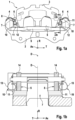
- Figs. 5 and 6 is not in accordance with the invention.
- a cuboid-shaped flat sheet blank is provided with a lateral and approximately centrally extending notch 21, a free cut, or a slot, in order to thereby produce two interconnected, parallel, and approximately equally strong spring legs 13a,b, which may be spread apart in a rhombus- or diamond-shaped manner and thus bent at an angle to one another, as can be seen from the figure.
- Fig. 5 + 6 is also recessed into a recess 23 of the housing 3.
- the return spring 10 engages after Fig. 5 + 6 but exclusively a part of the rear side of the back plate 14, is permanently attached exclusively to the rear side of the back plate 14 by means of the base section 11 and in no way encompasses the back plate 14, which limits the sheet metal consumption.
- machining from the seat on the brake holder 2 to the defined contact point of the free end 22 of the spring leg 13b is particularly recommended.
- a significant advantage of this design is the maximized, efficient use of the flat sheet material with the smallest possible axial height, so that with slightly increased effort, an optimized cost-benefit ratio is achieved for the development of an effective and simultaneously miniaturized return spring for particularly critical installation spaces.
- the second embodiment according to Fig. 7 + 8 combines some features of the first variant.
- the meandering and flat, essentially U-shaped spring leg 13, with its placement in the recess 23, is fundamentally similar to the second variant, but additionally integrates the fastening clip function, so that overall, a replaceable return spring 10 is provided, which comprises the retaining tab 16, sliding skid 15, and spring leg 13, and wherein the back plate 14 is resiliently gripped (like a clothespin) at the distal end by the hammerhead-shaped claw 6 of the retaining tab 16.
- the connected spring leg 13 does not extend radially (cf. Fig. 2-4) but tangentially - i.e., stretched in the circumferential direction - to the back plate 14.
- the spring leg 13 is bent several times in a loop-like or meander-like manner.
- the spring leg can be provided with a double S-shape, i.e., artificially significantly extended, which enables its spring properties and, in particular, an elastically and/or plastically stored travel reserve in this return spring 10 to compensate for comparatively large wear away from the friction material 19.
- the second variant is recommended for all those reinforced friction lining arrangements 5 with hammer-head-shaped claws 6 whose back plate rear side can be used for spring fixations to a limited extent, because, for example, one or more elevations modeled on the EP 1 217 247 B1 present.
Landscapes
- Engineering & Computer Science (AREA)
- General Engineering & Computer Science (AREA)
- Mechanical Engineering (AREA)
- Braking Arrangements (AREA)
Priority Applications (1)
| Application Number | Priority Date | Filing Date | Title |
|---|---|---|---|
| PL17704754.5T PL3417187T5 (pl) | 2016-02-18 | 2017-02-10 | Układ okładzin ciernych ze sprężyną powrotną do ograniczania luzu powietrznego w samochodowym hamulcu tarczowym z częściowymi okładzinami |
Applications Claiming Priority (2)
| Application Number | Priority Date | Filing Date | Title |
|---|---|---|---|
| DE102016202520.1A DE102016202520A1 (de) | 2016-02-18 | 2016-02-18 | Reibbelaganordnung mit Rückstellfeder zur Lüftspiellimitierung für eine Kraftfahrzeugteilbelagscheibenbremse |
| PCT/EP2017/053048 WO2017140598A1 (de) | 2016-02-18 | 2017-02-10 | Reibbelaganordnung mit rückstellfeder zur lüftspiellimitierung für eine kraftfahrzeugteilbelagscheibenbremse |
Publications (3)
| Publication Number | Publication Date |
|---|---|
| EP3417187A1 EP3417187A1 (de) | 2018-12-26 |
| EP3417187B1 EP3417187B1 (de) | 2021-01-13 |
| EP3417187B2 true EP3417187B2 (de) | 2025-06-04 |
Family
ID=58018107
Family Applications (1)
| Application Number | Title | Priority Date | Filing Date |
|---|---|---|---|
| EP17704754.5A Active EP3417187B2 (de) | 2016-02-18 | 2017-02-10 | Reibbelaganordnung mit rückstellfeder zur lüftspiellimitierung für eine kraftfahrzeugteilbelagscheibenbremse |
Country Status (10)
| Country | Link |
|---|---|
| US (1) | US11209056B2 (enExample) |
| EP (1) | EP3417187B2 (enExample) |
| JP (1) | JP6920320B2 (enExample) |
| KR (1) | KR102148589B1 (enExample) |
| CN (2) | CN118128847A (enExample) |
| DE (1) | DE102016202520A1 (enExample) |
| DK (1) | DK3417187T4 (enExample) |
| ES (1) | ES2858749T5 (enExample) |
| PL (1) | PL3417187T5 (enExample) |
| WO (1) | WO2017140598A1 (enExample) |
Families Citing this family (11)
| Publication number | Priority date | Publication date | Assignee | Title |
|---|---|---|---|---|
| CN108825682A (zh) * | 2018-06-19 | 2018-11-16 | 张思维 | 具有恒回复力复位机构的低拖磨制动衬块总成 |
| DE102019205500B4 (de) * | 2019-04-16 | 2025-06-12 | Zf Active Safety Gmbh | Bremsbelagrückstelleinrichtung für eine Fahrzeugbremsanlage |
| DE102019212896A1 (de) | 2019-04-17 | 2020-10-22 | Continental Teves Ag & Co. Ohg | Kraftfahrzeugscheibenbremsbelag mit Reibbelagrückstellfederbaugruppe |
| FR3097923B1 (fr) * | 2019-06-26 | 2022-07-29 | Foundation Brakes France | « Frein à disque comportant au moins un ressort de rappel élastique d'un patin de freinage, ressort de rappel élastique, kit de remplacement et procédé de montage » |
| DE102019210316A1 (de) * | 2019-07-12 | 2021-01-14 | Zf Active Safety Gmbh | Bremsvorrichtung für ein Kraftfahrzeug mit einer Rückstellvorrichtung |
| JP7426245B2 (ja) * | 2020-01-15 | 2024-02-01 | 曙ブレーキ工業株式会社 | ピン受金具付きディスクブレーキ用パッド及びディスクブレーキ装置 |
| DE102020101058B4 (de) | 2020-01-17 | 2025-05-22 | Knorr-Bremse Systeme für Nutzfahrzeuge GmbH | Scheibenbremse für ein Nutzfahrzeug und Bremsbelagsatz |
| KR20230008412A (ko) * | 2021-07-07 | 2023-01-16 | 현대모비스 주식회사 | 차량용 브레이크 장치 |
| JP7618512B2 (ja) * | 2021-07-07 | 2025-01-21 | 曙ブレーキ工業株式会社 | ディスクブレーキ装置用パッドクリップ及びディスクブレーキ装置 |
| CN113915260B (zh) * | 2021-09-30 | 2023-07-28 | 浙江万安科技股份有限公司 | 一种制动器 |
| CN115098977B (zh) * | 2022-07-20 | 2024-07-05 | 重庆大学 | 一种浮动支撑摩擦片组件冲击动载计算方法 |
Citations (8)
| Publication number | Priority date | Publication date | Assignee | Title |
|---|---|---|---|---|
| JPS56131038U (enExample) † | 1980-03-08 | 1981-10-05 | ||
| US4364455A (en) † | 1979-06-20 | 1982-12-21 | Tokico Ltd. | Retraction spring for disc brake pads |
| DE3538320A1 (de) † | 1984-10-29 | 1986-04-30 | Lucas Industries P.L.C., Birmingham, West Midlands | Bremsbacke mit rueckstellfeder |
| JP2008241046A (ja) † | 2008-06-02 | 2008-10-09 | Hitachi Ltd | ディスクブレーキ |
| US20110168503A1 (en) † | 2010-05-27 | 2011-07-14 | Akebono Corporation | Pad retraction device |
| DE102012016737A1 (de) † | 2012-08-23 | 2014-02-27 | Lucas Automotive Gmbh | Scheibenbremse für ein Kraftfahrzeug mit plastisch deformierbarer Rückstellfeder und Rückstellfeder |
| US20140367208A1 (en) † | 2013-06-18 | 2014-12-18 | Nissin Kogyo Co., Ltd. | Vehicle disc brake |
| DE202015104454U1 (de) † | 2014-08-25 | 2015-10-08 | Akebono Brake Industry Co., Ltd. | Mehrteilige Belagklammer |
Family Cites Families (21)
| Publication number | Priority date | Publication date | Assignee | Title |
|---|---|---|---|---|
| JPS562432U (enExample) | 1979-06-20 | 1981-01-10 | ||
| JP3085799B2 (ja) * | 1992-09-22 | 2000-09-11 | アイシン精機株式会社 | 車両用ディスクブレーキ |
| DE20011435U1 (de) * | 2000-07-05 | 2000-11-30 | Honeywell Bremsbelag GmbH, 21509 Glinde | Reibbelag für Scheibenbremsen, insbesondere für Straßen- und Schienenfahrzeuge |
| DE10064168B4 (de) | 2000-12-22 | 2023-06-15 | Continental Automotive Technologies GmbH | Bremsbelag für eine Teilbelagscheibenbremse |
| EP1430233A1 (en) * | 2001-09-25 | 2004-06-23 | Kelsey-Hayes Company | Pad retraction spring for a brake shoe assembly of a disc brake assembly |
| DE10238734A1 (de) | 2002-08-23 | 2004-03-04 | Continental Teves Ag & Co. Ohg | Schwimmsattel-Scheibenbremse mit einer Bremsbelagfeder |
| US20060237269A1 (en) | 2005-04-25 | 2006-10-26 | Muhammad Farooq | Pad retaining clip |
| JP2007315577A (ja) * | 2006-05-29 | 2007-12-06 | Toyota Motor Corp | ディスクブレーキ装置 |
| FR2925636B1 (fr) * | 2007-12-21 | 2010-04-02 | Bosch Gmbh Robert | Systeme de montage de patin de frein a disque. |
| DE102009022633A1 (de) * | 2009-03-25 | 2010-10-14 | Continental Teves Ag & Co. Ohg | Teilbelagscheibenbremse mit einer Federanordnung zur Lüftspielverbesserung sowie Federanordnung |
| DE102010043898A1 (de) * | 2010-06-02 | 2011-12-08 | Continental Teves Ag & Co. Ohg | Festsattelbremse und Bremsbelag für eine Festsattelbremse |
| US8376092B2 (en) * | 2011-02-10 | 2013-02-19 | Akebono Brake Corp. | Pad retraction device |
| JP5184693B2 (ja) | 2011-11-21 | 2013-04-17 | 日立オートモティブシステムズ株式会社 | ディスクブレーキ |
| FR2984438B1 (fr) * | 2011-12-15 | 2014-01-17 | Bosch Gmbh Robert | Ressort radial de patin de frein a disque et patins de frein ainsi que freins equipes de tels ressorts radiaux |
| BR112015005787B1 (pt) * | 2012-09-25 | 2022-02-22 | Hitachi Astemo, Ltd | Freio a disco |
| FR3004500B1 (fr) * | 2013-04-16 | 2016-02-05 | Chassis Brakes Int Bv | "frein a disque equipe de moyens de rappel elastique des patins de freinage et equipe de moyens de rattrapage, par deformation plastique, du jeu d'usure des patins" |
| DE102013207424B4 (de) * | 2013-04-24 | 2025-02-20 | Continental Automotive Technologies GmbH | Federanordnung zur Lüftspielverbesserung für eine Teilbelagscheibenbremse |
| FR3027081B1 (fr) * | 2014-10-10 | 2016-12-23 | Chassis Brakes Int Bv | "frein a disque a etrier coulissant comportant un ressort central de rappel elastique d'un patin de freinage exterieur comportant des moyens de rattrapage du jeu d'usure, ressort et kit de remplacement" |
| FR3027080B1 (fr) * | 2014-10-10 | 2018-03-09 | Chassis Brakes International B.V. | "ressort de rappel elastique d'un patin de freinage comportant des moyens de rattrapage du jeu d'usure, frein a disque et kit de remplacement" |
| FR3032505B1 (fr) * | 2015-02-06 | 2017-03-17 | Foundation Brakes France | "frein a disque comportant au moins un ressort de rappel elastique d'un patin de freinage, ressort de rappel elastique, patin de freinage et kit de remplacement" |
| FR3033378B1 (fr) * | 2015-03-06 | 2018-08-10 | Foundation Brakes France | "frein a disque comportant au moins un ressort de rappel elastique d'un patin de freinage, ressort de rappel elastique, glissiere de guidage et kit de remplacement" |
-
2016
- 2016-02-18 DE DE102016202520.1A patent/DE102016202520A1/de active Pending
-
2017
- 2017-02-10 CN CN202410395796.9A patent/CN118128847A/zh active Pending
- 2017-02-10 US US16/069,020 patent/US11209056B2/en active Active
- 2017-02-10 PL PL17704754.5T patent/PL3417187T5/pl unknown
- 2017-02-10 ES ES17704754T patent/ES2858749T5/es active Active
- 2017-02-10 WO PCT/EP2017/053048 patent/WO2017140598A1/de not_active Ceased
- 2017-02-10 JP JP2018540035A patent/JP6920320B2/ja active Active
- 2017-02-10 CN CN201780008284.0A patent/CN109073002A/zh active Pending
- 2017-02-10 DK DK17704754.5T patent/DK3417187T4/da active
- 2017-02-10 KR KR1020187026212A patent/KR102148589B1/ko active Active
- 2017-02-10 EP EP17704754.5A patent/EP3417187B2/de active Active
Patent Citations (8)
| Publication number | Priority date | Publication date | Assignee | Title |
|---|---|---|---|---|
| US4364455A (en) † | 1979-06-20 | 1982-12-21 | Tokico Ltd. | Retraction spring for disc brake pads |
| JPS56131038U (enExample) † | 1980-03-08 | 1981-10-05 | ||
| DE3538320A1 (de) † | 1984-10-29 | 1986-04-30 | Lucas Industries P.L.C., Birmingham, West Midlands | Bremsbacke mit rueckstellfeder |
| JP2008241046A (ja) † | 2008-06-02 | 2008-10-09 | Hitachi Ltd | ディスクブレーキ |
| US20110168503A1 (en) † | 2010-05-27 | 2011-07-14 | Akebono Corporation | Pad retraction device |
| DE102012016737A1 (de) † | 2012-08-23 | 2014-02-27 | Lucas Automotive Gmbh | Scheibenbremse für ein Kraftfahrzeug mit plastisch deformierbarer Rückstellfeder und Rückstellfeder |
| US20140367208A1 (en) † | 2013-06-18 | 2014-12-18 | Nissin Kogyo Co., Ltd. | Vehicle disc brake |
| DE202015104454U1 (de) † | 2014-08-25 | 2015-10-08 | Akebono Brake Industry Co., Ltd. | Mehrteilige Belagklammer |
Non-Patent Citations (1)
| Title |
|---|
| "Bremsenhandbuch. Grundlagen, Komponenten, Systeme, Fahrdynamik", 1 January 2012, SPRINGER VIEWEG, article BREUER BERT, BILL, K. H.: "Kapitel 7: Aufbau und Komponenten von Pkw-Bremsanlage", pages: 113 - 163, XP055866631 † |
Also Published As
| Publication number | Publication date |
|---|---|
| PL3417187T3 (pl) | 2021-07-05 |
| ES2858749T3 (es) | 2021-09-30 |
| EP3417187B1 (de) | 2021-01-13 |
| CN118128847A (zh) | 2024-06-04 |
| PL3417187T5 (pl) | 2025-09-22 |
| US20190024736A1 (en) | 2019-01-24 |
| DK3417187T4 (da) | 2025-08-25 |
| US11209056B2 (en) | 2021-12-28 |
| JP6920320B2 (ja) | 2021-08-18 |
| WO2017140598A1 (de) | 2017-08-24 |
| DK3417187T3 (da) | 2021-04-12 |
| DE102016202520A1 (de) | 2017-08-24 |
| JP2019503464A (ja) | 2019-02-07 |
| BR112018015509A2 (pt) | 2018-12-18 |
| KR20180108826A (ko) | 2018-10-04 |
| ES2858749T5 (en) | 2025-10-20 |
| KR102148589B1 (ko) | 2020-08-26 |
| EP3417187A1 (de) | 2018-12-26 |
| CN109073002A (zh) | 2018-12-21 |
Similar Documents
| Publication | Publication Date | Title |
|---|---|---|
| EP3417187B2 (de) | Reibbelaganordnung mit rückstellfeder zur lüftspiellimitierung für eine kraftfahrzeugteilbelagscheibenbremse | |
| EP2649340B1 (de) | Kennzeichnungsträger zum kennzeichnen einer schwimmsattelbremse | |
| EP3359843B1 (de) | Scheibenbremse für ein nutzfahrzeug | |
| EP3350058B1 (de) | Lenksäule für kraftfahrzeuge mit energieabsorber für den crashfall | |
| EP3135948B1 (de) | Vorrichtung zur befestigung eines verschleisssensors an einem bremshebel einer fahrzeugbremse | |
| EP2923105B1 (de) | Scheibenbremse eines kraftfahrzeugs | |
| WO2007088202A1 (de) | Befestigungselement für fahrzeugteile | |
| EP2651743A1 (de) | Lenksäule für ein kraftfahrzeug | |
| EP3956582B1 (de) | Kraftfahrzeugscheibenbremsbelag mit reibbelagrückstellfeder | |
| EP2855960A1 (de) | Führungsmittel für eine bremsbelaganordnung | |
| EP3198166A1 (de) | Führungsmittel für eine bremsbelaganordnung einer scheibenbremse und scheibenbremse | |
| DE4135387C1 (enExample) | ||
| WO2016034378A1 (de) | Bremsbelaghalterung einer scheibenbremse, scheibenbremse und bremsbelag | |
| DE102017129672B4 (de) | Scheibenbremse für ein Nutzfahrzeug und Bremsbelagsatz | |
| DE102013207424A1 (de) | Teilbelagscheibenbremse mit einer Federanordnung zur Lüftspielverbesserung sowie Federanordnung | |
| WO2008022781A1 (de) | Ausgleichsgewicht für den unwuchtausgleich eines fahrzeugrades | |
| DE102009007201A1 (de) | Scheibenbremse mit einer Federanordnung | |
| EP1227260B1 (de) | Schwimmsattelscheibenbremse mit einer Federanordnung | |
| EP2012037A1 (de) | Federclip zur Festigung eines Sensors an einer Bremsbelag-Rückenplatte einer Scheibenbremse | |
| DE102015209785B4 (de) | Pneumatischer Bremskraftverstärker | |
| EP2679853B2 (de) | Scheibenbremse für ein Nutzfahrzeug sowie Bremsbelag für eine Scheibenbremse | |
| DE102022101381A1 (de) | Scheibenbremse | |
| DE102006007017B4 (de) | Bremsbelaghalterung und Bremsbelag für eine Scheibenbremse | |
| DE102004034259A1 (de) | Türfeststeller | |
| WO2015018693A1 (de) | Bremsbelaganordnung mit verschleissanzeiger sowie verschleissanzeiger hierfür |
Legal Events
| Date | Code | Title | Description |
|---|---|---|---|
| STAA | Information on the status of an ep patent application or granted ep patent |
Free format text: STATUS: UNKNOWN |
|
| STAA | Information on the status of an ep patent application or granted ep patent |
Free format text: STATUS: THE INTERNATIONAL PUBLICATION HAS BEEN MADE |
|
| PUAI | Public reference made under article 153(3) epc to a published international application that has entered the european phase |
Free format text: ORIGINAL CODE: 0009012 |
|
| STAA | Information on the status of an ep patent application or granted ep patent |
Free format text: STATUS: REQUEST FOR EXAMINATION WAS MADE |
|
| 17P | Request for examination filed |
Effective date: 20180918 |
|
| AK | Designated contracting states |
Kind code of ref document: A1 Designated state(s): AL AT BE BG CH CY CZ DE DK EE ES FI FR GB GR HR HU IE IS IT LI LT LU LV MC MK MT NL NO PL PT RO RS SE SI SK SM TR |
|
| AX | Request for extension of the european patent |
Extension state: BA ME |
|
| DAV | Request for validation of the european patent (deleted) | ||
| DAX | Request for extension of the european patent (deleted) | ||
| STAA | Information on the status of an ep patent application or granted ep patent |
Free format text: STATUS: EXAMINATION IS IN PROGRESS |
|
| 17Q | First examination report despatched |
Effective date: 20191203 |
|
| GRAP | Despatch of communication of intention to grant a patent |
Free format text: ORIGINAL CODE: EPIDOSNIGR1 |
|
| STAA | Information on the status of an ep patent application or granted ep patent |
Free format text: STATUS: GRANT OF PATENT IS INTENDED |
|
| INTG | Intention to grant announced |
Effective date: 20200917 |
|
| GRAS | Grant fee paid |
Free format text: ORIGINAL CODE: EPIDOSNIGR3 |
|
| GRAA | (expected) grant |
Free format text: ORIGINAL CODE: 0009210 |
|
| STAA | Information on the status of an ep patent application or granted ep patent |
Free format text: STATUS: THE PATENT HAS BEEN GRANTED |
|
| AK | Designated contracting states |
Kind code of ref document: B1 Designated state(s): AL AT BE BG CH CY CZ DE DK EE ES FI FR GB GR HR HU IE IS IT LI LT LU LV MC MK MT NL NO PL PT RO RS SE SI SK SM TR |
|
| REG | Reference to a national code |
Ref country code: GB Ref legal event code: FG4D Free format text: NOT ENGLISH |
|
| REG | Reference to a national code |
Ref country code: CH Ref legal event code: EP |
|
| REG | Reference to a national code |
Ref country code: IE Ref legal event code: FG4D Free format text: LANGUAGE OF EP DOCUMENT: GERMAN |
|
| REG | Reference to a national code |
Ref country code: DE Ref legal event code: R096 Ref document number: 502017009044 Country of ref document: DE |
|
| REG | Reference to a national code |
Ref country code: AT Ref legal event code: REF Ref document number: 1354805 Country of ref document: AT Kind code of ref document: T Effective date: 20210215 |
|
| REG | Reference to a national code |
Ref country code: RO Ref legal event code: EPE |
|
| REG | Reference to a national code |
Ref country code: DK Ref legal event code: T3 Effective date: 20210406 |
|
| REG | Reference to a national code |
Ref country code: SK Ref legal event code: T3 Ref document number: E 36679 Country of ref document: SK |
|
| REG | Reference to a national code |
Ref country code: NL Ref legal event code: MP Effective date: 20210113 |
|
| REG | Reference to a national code |
Ref country code: LT Ref legal event code: MG9D |
|
| PG25 | Lapsed in a contracting state [announced via postgrant information from national office to epo] |
Ref country code: LT Free format text: LAPSE BECAUSE OF FAILURE TO SUBMIT A TRANSLATION OF THE DESCRIPTION OR TO PAY THE FEE WITHIN THE PRESCRIBED TIME-LIMIT Effective date: 20210113 Ref country code: BG Free format text: LAPSE BECAUSE OF FAILURE TO SUBMIT A TRANSLATION OF THE DESCRIPTION OR TO PAY THE FEE WITHIN THE PRESCRIBED TIME-LIMIT Effective date: 20210413 Ref country code: GR Free format text: LAPSE BECAUSE OF FAILURE TO SUBMIT A TRANSLATION OF THE DESCRIPTION OR TO PAY THE FEE WITHIN THE PRESCRIBED TIME-LIMIT Effective date: 20210414 Ref country code: FI Free format text: LAPSE BECAUSE OF FAILURE TO SUBMIT A TRANSLATION OF THE DESCRIPTION OR TO PAY THE FEE WITHIN THE PRESCRIBED TIME-LIMIT Effective date: 20210113 Ref country code: HR Free format text: LAPSE BECAUSE OF FAILURE TO SUBMIT A TRANSLATION OF THE DESCRIPTION OR TO PAY THE FEE WITHIN THE PRESCRIBED TIME-LIMIT Effective date: 20210113 Ref country code: PT Free format text: LAPSE BECAUSE OF FAILURE TO SUBMIT A TRANSLATION OF THE DESCRIPTION OR TO PAY THE FEE WITHIN THE PRESCRIBED TIME-LIMIT Effective date: 20210513 Ref country code: NO Free format text: LAPSE BECAUSE OF FAILURE TO SUBMIT A TRANSLATION OF THE DESCRIPTION OR TO PAY THE FEE WITHIN THE PRESCRIBED TIME-LIMIT Effective date: 20210413 |
|
| PG25 | Lapsed in a contracting state [announced via postgrant information from national office to epo] |
Ref country code: SE Free format text: LAPSE BECAUSE OF FAILURE TO SUBMIT A TRANSLATION OF THE DESCRIPTION OR TO PAY THE FEE WITHIN THE PRESCRIBED TIME-LIMIT Effective date: 20210113 Ref country code: RS Free format text: LAPSE BECAUSE OF FAILURE TO SUBMIT A TRANSLATION OF THE DESCRIPTION OR TO PAY THE FEE WITHIN THE PRESCRIBED TIME-LIMIT Effective date: 20210113 Ref country code: LV Free format text: LAPSE BECAUSE OF FAILURE TO SUBMIT A TRANSLATION OF THE DESCRIPTION OR TO PAY THE FEE WITHIN THE PRESCRIBED TIME-LIMIT Effective date: 20210113 |
|
| PG25 | Lapsed in a contracting state [announced via postgrant information from national office to epo] |
Ref country code: IS Free format text: LAPSE BECAUSE OF FAILURE TO SUBMIT A TRANSLATION OF THE DESCRIPTION OR TO PAY THE FEE WITHIN THE PRESCRIBED TIME-LIMIT Effective date: 20210513 |
|
| REG | Reference to a national code |
Ref country code: ES Ref legal event code: FG2A Ref document number: 2858749 Country of ref document: ES Kind code of ref document: T3 Effective date: 20210930 |
|
| REG | Reference to a national code |
Ref country code: DE Ref legal event code: R026 Ref document number: 502017009044 Country of ref document: DE |
|
| PLBI | Opposition filed |
Free format text: ORIGINAL CODE: 0009260 |
|
| PLAX | Notice of opposition and request to file observation + time limit sent |
Free format text: ORIGINAL CODE: EPIDOSNOBS2 |
|
| REG | Reference to a national code |
Ref country code: BE Ref legal event code: MM Effective date: 20210228 |
|
| PG25 | Lapsed in a contracting state [announced via postgrant information from national office to epo] |
Ref country code: LI Free format text: LAPSE BECAUSE OF NON-PAYMENT OF DUE FEES Effective date: 20210228 Ref country code: MC Free format text: LAPSE BECAUSE OF FAILURE TO SUBMIT A TRANSLATION OF THE DESCRIPTION OR TO PAY THE FEE WITHIN THE PRESCRIBED TIME-LIMIT Effective date: 20210113 Ref country code: LU Free format text: LAPSE BECAUSE OF NON-PAYMENT OF DUE FEES Effective date: 20210210 Ref country code: CZ Free format text: LAPSE BECAUSE OF FAILURE TO SUBMIT A TRANSLATION OF THE DESCRIPTION OR TO PAY THE FEE WITHIN THE PRESCRIBED TIME-LIMIT Effective date: 20210113 Ref country code: EE Free format text: LAPSE BECAUSE OF FAILURE TO SUBMIT A TRANSLATION OF THE DESCRIPTION OR TO PAY THE FEE WITHIN THE PRESCRIBED TIME-LIMIT Effective date: 20210113 Ref country code: SM Free format text: LAPSE BECAUSE OF FAILURE TO SUBMIT A TRANSLATION OF THE DESCRIPTION OR TO PAY THE FEE WITHIN THE PRESCRIBED TIME-LIMIT Effective date: 20210113 Ref country code: CH Free format text: LAPSE BECAUSE OF NON-PAYMENT OF DUE FEES Effective date: 20210228 |
|
| 26 | Opposition filed |
Opponent name: ZF FRIEDRICHSHAFEN AG Effective date: 20211006 |
|
| PG25 | Lapsed in a contracting state [announced via postgrant information from national office to epo] |
Ref country code: IE Free format text: LAPSE BECAUSE OF NON-PAYMENT OF DUE FEES Effective date: 20210210 Ref country code: AL Free format text: LAPSE BECAUSE OF FAILURE TO SUBMIT A TRANSLATION OF THE DESCRIPTION OR TO PAY THE FEE WITHIN THE PRESCRIBED TIME-LIMIT Effective date: 20210113 |
|
| PLBB | Reply of patent proprietor to notice(s) of opposition received |
Free format text: ORIGINAL CODE: EPIDOSNOBS3 |
|
| PG25 | Lapsed in a contracting state [announced via postgrant information from national office to epo] |
Ref country code: SI Free format text: LAPSE BECAUSE OF FAILURE TO SUBMIT A TRANSLATION OF THE DESCRIPTION OR TO PAY THE FEE WITHIN THE PRESCRIBED TIME-LIMIT Effective date: 20210113 |
|
| RAP2 | Party data changed (patent owner data changed or rights of a patent transferred) |
Owner name: CONTINENTAL AUTOMOTIVE TECHNOLOGIES GMBH |
|
| PG25 | Lapsed in a contracting state [announced via postgrant information from national office to epo] |
Ref country code: BE Free format text: LAPSE BECAUSE OF NON-PAYMENT OF DUE FEES Effective date: 20210228 |
|
| REG | Reference to a national code |
Ref country code: DE Ref legal event code: R081 Ref document number: 502017009044 Country of ref document: DE Owner name: CONTINENTAL AUTOMOTIVE TECHNOLOGIES GMBH, DE Free format text: FORMER OWNER: CONTINENTAL TEVES AG & CO. OHG, 60488 FRANKFURT, DE |
|
| REG | Reference to a national code |
Ref country code: GB Ref legal event code: 732E Free format text: REGISTERED BETWEEN 20230216 AND 20230222 |
|
| REG | Reference to a national code |
Ref country code: SK Ref legal event code: PC4A Ref document number: E 36679 Country of ref document: SK Owner name: CONTINENTAL AUTOMOTIVE TECHNOLOGIES GMBH, HANN, DE Free format text: FORMER OWNER: CONTINENTAL TEVES AG & CO. OHG, FRANKFURT AM MAIN, DE Effective date: 20230227 |
|
| REG | Reference to a national code |
Ref country code: AT Ref legal event code: MM01 Ref document number: 1354805 Country of ref document: AT Kind code of ref document: T Effective date: 20220210 |
|
| PG25 | Lapsed in a contracting state [announced via postgrant information from national office to epo] |
Ref country code: AT Free format text: LAPSE BECAUSE OF NON-PAYMENT OF DUE FEES Effective date: 20220210 |
|
| P01 | Opt-out of the competence of the unified patent court (upc) registered |
Effective date: 20230522 |
|
| PG25 | Lapsed in a contracting state [announced via postgrant information from national office to epo] |
Ref country code: NL Free format text: LAPSE BECAUSE OF NON-PAYMENT OF DUE FEES Effective date: 20210113 Ref country code: CY Free format text: LAPSE BECAUSE OF FAILURE TO SUBMIT A TRANSLATION OF THE DESCRIPTION OR TO PAY THE FEE WITHIN THE PRESCRIBED TIME-LIMIT Effective date: 20210113 |
|
| PG25 | Lapsed in a contracting state [announced via postgrant information from national office to epo] |
Ref country code: HU Free format text: LAPSE BECAUSE OF FAILURE TO SUBMIT A TRANSLATION OF THE DESCRIPTION OR TO PAY THE FEE WITHIN THE PRESCRIBED TIME-LIMIT; INVALID AB INITIO Effective date: 20170210 |
|
| REG | Reference to a national code |
Ref country code: DE Ref legal event code: R081 Ref document number: 502017009044 Country of ref document: DE Owner name: CONTINENTAL AUTOMOTIVE TECHNOLOGIES GMBH, DE Free format text: FORMER OWNER: CONTINENTAL AUTOMOTIVE TECHNOLOGIES GMBH, 30165 HANNOVER, DE |
|
| RAP4 | Party data changed (patent owner data changed or rights of a patent transferred) |
Owner name: CONTINENTAL AUTOMOTIVE TECHNOLOGIES GMBH |
|
| PG25 | Lapsed in a contracting state [announced via postgrant information from national office to epo] |
Ref country code: MK Free format text: LAPSE BECAUSE OF FAILURE TO SUBMIT A TRANSLATION OF THE DESCRIPTION OR TO PAY THE FEE WITHIN THE PRESCRIBED TIME-LIMIT Effective date: 20210113 |
|
| REG | Reference to a national code |
Ref country code: CH Ref legal event code: PK Free format text: DIE PUBLIKATION VOM 27.03.2024 WURDE AM 24.04.2024 IRRTUEMLICHERWEISE ERNEUT PUBLIZIERT. LA PUBLICATION DU 27.03.2024 A ETE REPUBLIEE PAR ERREUR LE 24.04.2024. LA PUBBLICAZIONE DEL 27.03.2024 E STATA ERRONEAMENTE RIPUBBLICATA IL 24.04.2024. |
|
| PLAB | Opposition data, opponent's data or that of the opponent's representative modified |
Free format text: ORIGINAL CODE: 0009299OPPO |
|
| R26 | Opposition filed (corrected) |
Opponent name: ZF FRIEDRICHSHAFEN AG Effective date: 20211006 |
|
| PG25 | Lapsed in a contracting state [announced via postgrant information from national office to epo] |
Ref country code: MT Free format text: LAPSE BECAUSE OF FAILURE TO SUBMIT A TRANSLATION OF THE DESCRIPTION OR TO PAY THE FEE WITHIN THE PRESCRIBED TIME-LIMIT Effective date: 20210113 |
|
| PGFP | Annual fee paid to national office [announced via postgrant information from national office to epo] |
Ref country code: DE Payment date: 20250228 Year of fee payment: 9 |
|
| PGFP | Annual fee paid to national office [announced via postgrant information from national office to epo] |
Ref country code: DK Payment date: 20250224 Year of fee payment: 9 Ref country code: RO Payment date: 20250205 Year of fee payment: 9 |
|
| PGFP | Annual fee paid to national office [announced via postgrant information from national office to epo] |
Ref country code: FR Payment date: 20250221 Year of fee payment: 9 Ref country code: PL Payment date: 20250205 Year of fee payment: 9 |
|
| PGFP | Annual fee paid to national office [announced via postgrant information from national office to epo] |
Ref country code: GB Payment date: 20250220 Year of fee payment: 9 Ref country code: IT Payment date: 20250224 Year of fee payment: 9 Ref country code: SK Payment date: 20250205 Year of fee payment: 9 |
|
| PGFP | Annual fee paid to national office [announced via postgrant information from national office to epo] |
Ref country code: TR Payment date: 20250203 Year of fee payment: 9 |
|
| PUAH | Patent maintained in amended form |
Free format text: ORIGINAL CODE: 0009272 |
|
| STAA | Information on the status of an ep patent application or granted ep patent |
Free format text: STATUS: PATENT MAINTAINED AS AMENDED |
|
| 27A | Patent maintained in amended form |
Effective date: 20250604 |
|
| AK | Designated contracting states |
Kind code of ref document: B2 Designated state(s): AL AT BE BG CH CY CZ DE DK EE ES FI FR GB GR HR HU IE IS IT LI LT LU LV MC MK MT NL NO PL PT RO RS SE SI SK SM TR |
|
| REG | Reference to a national code |
Ref country code: DE Ref legal event code: R102 Ref document number: 502017009044 Country of ref document: DE |
|
| PGFP | Annual fee paid to national office [announced via postgrant information from national office to epo] |
Ref country code: ES Payment date: 20250331 Year of fee payment: 9 |
|
| REG | Reference to a national code |
Ref country code: DK Ref legal event code: T4 Effective date: 20250822 |
|
| REG | Reference to a national code |
Ref country code: SK Ref legal event code: T5 Ref document number: E 36679 Country of ref document: SK Ref country code: SK Ref legal event code: TC4A Ref document number: E 36679 Country of ref document: SK Owner name: CONTINENTAL AUTOMOTIVE TECHNOLOGIES GMBH, HANN, DE Effective date: 20250925 |
|
| REG | Reference to a national code |
Ref country code: ES Ref legal event code: DC2A Ref document number: 2858749 Country of ref document: ES Kind code of ref document: T5 Effective date: 20251020 |