EP3401475B1 - Système d'armatures - Google Patents
Système d'armatures Download PDFInfo
- Publication number
- EP3401475B1 EP3401475B1 EP18179199.7A EP18179199A EP3401475B1 EP 3401475 B1 EP3401475 B1 EP 3401475B1 EP 18179199 A EP18179199 A EP 18179199A EP 3401475 B1 EP3401475 B1 EP 3401475B1
- Authority
- EP
- European Patent Office
- Prior art keywords
- locking bar
- fitting arrangement
- locking
- entrainment element
- actuation
- Prior art date
- Legal status (The legal status is an assumption and is not a legal conclusion. Google has not performed a legal analysis and makes no representation as to the accuracy of the status listed.)
- Active
Links
- 230000007246 mechanism Effects 0.000 claims description 18
- 230000007935 neutral effect Effects 0.000 claims description 15
- 230000008878 coupling Effects 0.000 claims description 8
- 238000010168 coupling process Methods 0.000 claims description 8
- 238000005859 coupling reaction Methods 0.000 claims description 8
- 238000006073 displacement reaction Methods 0.000 claims description 7
- 230000000694 effects Effects 0.000 claims description 3
- 230000000903 blocking effect Effects 0.000 description 15
- 238000010276 construction Methods 0.000 description 4
- 238000000034 method Methods 0.000 description 4
- 230000007704 transition Effects 0.000 description 2
- 230000009471 action Effects 0.000 description 1
- 230000008901 benefit Effects 0.000 description 1
- 230000008569 process Effects 0.000 description 1
Images


Classifications
-
- E—FIXED CONSTRUCTIONS
- E05—LOCKS; KEYS; WINDOW OR DOOR FITTINGS; SAFES
- E05D—HINGES OR SUSPENSION DEVICES FOR DOORS, WINDOWS OR WINGS
- E05D15/00—Suspension arrangements for wings
- E05D15/48—Suspension arrangements for wings allowing alternative movements
- E05D15/52—Suspension arrangements for wings allowing alternative movements for opening about a vertical as well as a horizontal axis
-
- E—FIXED CONSTRUCTIONS
- E05—LOCKS; KEYS; WINDOW OR DOOR FITTINGS; SAFES
- E05B—LOCKS; ACCESSORIES THEREFOR; HANDCUFFS
- E05B47/00—Operating or controlling locks or other fastening devices by electric or magnetic means
- E05B47/02—Movement of the bolt by electromagnetic means; Adaptation of locks, latches, or parts thereof, for movement of the bolt by electromagnetic means
- E05B47/026—Movement of the bolt by electromagnetic means; Adaptation of locks, latches, or parts thereof, for movement of the bolt by electromagnetic means the bolt moving rectilinearly
-
- E—FIXED CONSTRUCTIONS
- E05—LOCKS; KEYS; WINDOW OR DOOR FITTINGS; SAFES
- E05C—BOLTS OR FASTENING DEVICES FOR WINGS, SPECIALLY FOR DOORS OR WINDOWS
- E05C9/00—Arrangements of simultaneously actuated bolts or other securing devices at well-separated positions on the same wing
-
- E—FIXED CONSTRUCTIONS
- E05—LOCKS; KEYS; WINDOW OR DOOR FITTINGS; SAFES
- E05F—DEVICES FOR MOVING WINGS INTO OPEN OR CLOSED POSITION; CHECKS FOR WINGS; WING FITTINGS NOT OTHERWISE PROVIDED FOR, CONCERNED WITH THE FUNCTIONING OF THE WING
- E05F15/00—Power-operated mechanisms for wings
- E05F15/60—Power-operated mechanisms for wings using electrical actuators
- E05F15/603—Power-operated mechanisms for wings using electrical actuators using rotary electromotors
- E05F15/611—Power-operated mechanisms for wings using electrical actuators using rotary electromotors for swinging wings
-
- E—FIXED CONSTRUCTIONS
- E05—LOCKS; KEYS; WINDOW OR DOOR FITTINGS; SAFES
- E05B—LOCKS; ACCESSORIES THEREFOR; HANDCUFFS
- E05B47/00—Operating or controlling locks or other fastening devices by electric or magnetic means
- E05B47/0001—Operating or controlling locks or other fastening devices by electric or magnetic means with electric actuators; Constructional features thereof
- E05B47/0012—Operating or controlling locks or other fastening devices by electric or magnetic means with electric actuators; Constructional features thereof with rotary electromotors
- E05B2047/0013—Operating or controlling locks or other fastening devices by electric or magnetic means with electric actuators; Constructional features thereof with rotary electromotors more than one motor for the same function, e.g. for redundancy or increased power
-
- E—FIXED CONSTRUCTIONS
- E05—LOCKS; KEYS; WINDOW OR DOOR FITTINGS; SAFES
- E05B—LOCKS; ACCESSORIES THEREFOR; HANDCUFFS
- E05B47/00—Operating or controlling locks or other fastening devices by electric or magnetic means
- E05B47/0001—Operating or controlling locks or other fastening devices by electric or magnetic means with electric actuators; Constructional features thereof
- E05B2047/0014—Constructional features of actuators or power transmissions therefor
- E05B2047/0018—Details of actuator transmissions
- E05B2047/0023—Nuts or nut-like elements moving along a driven threaded axle
-
- E—FIXED CONSTRUCTIONS
- E05—LOCKS; KEYS; WINDOW OR DOOR FITTINGS; SAFES
- E05B—LOCKS; ACCESSORIES THEREFOR; HANDCUFFS
- E05B47/00—Operating or controlling locks or other fastening devices by electric or magnetic means
- E05B2047/0048—Circuits, feeding, monitoring
- E05B2047/0067—Monitoring
-
- E—FIXED CONSTRUCTIONS
- E05—LOCKS; KEYS; WINDOW OR DOOR FITTINGS; SAFES
- E05Y—INDEXING SCHEME RELATING TO HINGES OR OTHER SUSPENSION DEVICES FOR DOORS, WINDOWS OR WINGS AND DEVICES FOR MOVING WINGS INTO OPEN OR CLOSED POSITION, CHECKS FOR WINGS AND WING FITTINGS NOT OTHERWISE PROVIDED FOR, CONCERNED WITH THE FUNCTIONING OF THE WING
- E05Y2600/00—Mounting or coupling arrangements for elements provided for in this subclass
- E05Y2600/40—Mounting location; Visibility of the elements
- E05Y2600/46—Mounting location; Visibility of the elements in or on the wing
-
- E—FIXED CONSTRUCTIONS
- E05—LOCKS; KEYS; WINDOW OR DOOR FITTINGS; SAFES
- E05Y—INDEXING SCHEME RELATING TO HINGES OR OTHER SUSPENSION DEVICES FOR DOORS, WINDOWS OR WINGS AND DEVICES FOR MOVING WINGS INTO OPEN OR CLOSED POSITION, CHECKS FOR WINGS AND WING FITTINGS NOT OTHERWISE PROVIDED FOR, CONCERNED WITH THE FUNCTIONING OF THE WING
- E05Y2900/00—Application of doors, windows, wings or fittings thereof
- E05Y2900/10—Application of doors, windows, wings or fittings thereof for buildings or parts thereof
- E05Y2900/13—Application of doors, windows, wings or fittings thereof for buildings or parts thereof characterised by the type of wing
- E05Y2900/148—Windows
Definitions
- the present invention relates to a fitting arrangement for windows, doors or the like with a frame and with a wing, the fitting arrangement comprising on the wing side a locking bar, a mechanical - in particular manually operated - actuating device and at least one actuating motor.
- the fitting arrangement can optionally be operated by the actuating motor and the actuating device, i.e. the locking bar is displaceable and can be brought into a first and a second functional position both by the actuating motor and by the actuating device.
- Such motor-driven fitting arrangements increase ease of use and, for example, also enable remote-controlled actuation, e.g. to bring the wing in the frame from a closed position to a tilted position - and vice versa.
- the DE 196 03 770 A1 discloses a fitting arrangement with the features of the respective preamble of the independent claims.
- the actuating motor and components for drivingly coupling the actuating motor to the locking bar are designed to be arranged in a region of a lower edge of the wing, in the position of use.
- the actuating motor and the components mentioned are designed to be arranged in a region of a lower edge of a casement, for example in a window frame.
- This design is accompanied by the advantage that the energy required for actuating the fitting arrangement by the actuating motor can be supplied in a simple manner, since no complex wiring for power supply is required even when the sash is tilted. In this state, too, the lower edge of the wing is in close spatial contact with the frame assigned to the wing, so that corresponding electrical contacts can be designed to be comparatively simple.
- the actuating motor can be coupled to the locking rod in a drive-effective manner via a driver element, the locking rod having a drive pin which, in a drive-effectively coupled state, interacts with one of two mutually facing drive surfaces of the driver element which can be moved by the actuating motor.
- the driver element in this embodiment - figuratively speaking - is designed as a flat U-profile, the inner sides of the legs of the U-profile forming the drive surfaces. By moving the U-profile laterally, either one or the other inside of the U-profile can come into contact with the drive pin brought in order to be able to move it - and thus also the locking bar.
- the section of the U-profile connecting the legs defines the path that the driver element has to travel in order to move from a coupling with one of the drive surfaces to a coupling with the other drive surface.
- the section connecting the legs thus defines a kind of "idling between two drive-coupled states, in which a movement of the driver element is transmitted via the corresponding drive surface to the drive pin and thus ultimately to the locking bar.
- the actuating motor is assigned a pin-like driver element
- the locking bar comprises two drive surfaces, for example two lugs, a U-shaped coupling element, a recess and / or an opening between and into which the pin-like driver element intervenes.
- a driver element which is coupled to the actuating motor in a drive-effective manner, in particular in the form of a pin, is provided, which can be selectively brought into a drive-effective coupling with the locking bar and which engages through the locking bar so that the driver element protrudes from the wing.
- the driver element can not only be provided for driving the locking bar, but can also perform additional functions which are useful for reliable operation of the fitting arrangement.
- the driver element can be moved linearly.
- a control unit can be assigned to the actuating motor, which is designed such that the driver element is in a first position, in a second position and can be brought into a neutral position, the neutral position being in particular between the first and the second position.
- the control unit is designed in such a way that only the above-mentioned discrete positions can be taken and the taking of further intermediate positions is not provided.
- the control unit can be designed in such a way that the driver element can automatically be moved into the neutral position after reaching the first and the second position, so that the driver element is always brought back into a well-defined basic or neutral position by a method in the first or the second position.
- the driver element can be coupled to the locking bar in such a way that moving the driver element into the first position causes the locking bar to be moved into the first functional position and that moving the driving element into the second position causes the locking bar to be moved into the second functional position.
- the locking bar can be brought into a third functional position, which lies between the first and the second functional position. It is particularly advantageous if the locking bar and the driver element are configured such that the locking bar can be brought into the third functional position by actuating the actuating device without the driver element participating. In other words, the locking bar should also and in particular only be able to be brought into the third functional position without the cooperation of the actuating motor.
- the first functional position of the locking bar defines a locking position of the fitting arrangement, in which the sash is locked in the frame.
- the second functional position defines a tilt position of the Fitting arrangement in which the sash can be tilted in the frame.
- the third functional position can define a rotational position of the fitting arrangement, in which the sash can be moved in the frame by rotation, ie can be opened in the usual way.
- the length of the elongated hole in the longitudinal direction of the locking bar can - taking into account the expansion of the driver element in this direction - correspond to the distance required to move the locking bar from the first functional position into the second functional position. If the driver element is moved back into the neutral position after the method in one of the two positions, the configuration described above causes the driver element in the neutral position to be arranged again in the region of one of the ends of the elongated hole or even to strike the end. If a different functional position is to be assumed based on this situation, an actuation of the actuating motor and a corresponding movement of the driver element are immediately converted into a movement of the locking bar.
- the actuating motor is coupled to a threaded spindle in a drive-effective manner, the threaded spindle being in a drive-effective connection with the driver element, in particular via a spindle nut.
- the threaded spindle is in particular at least twice as long as the elongated hole of the locking bar.
- two actuating motors can be used be provided, which are arranged in particular coaxially.
- a threaded spindle is provided which is driven at both ends - preferably via a gear or also directly - by an actuating motor in each case.
- the locking bar can be arranged between the actuating motor and a faceplate, which at least in sections covers the locking bar with respect to the outer space of the wing and through which the driver element projects.
- the fitting arrangement can have a position determining device for determining the position of the locking bar.
- the position determining device comprises in particular a rotation angle sensor - for example a potentiometer - which is coupled to the locking rod via a gearwheel engaging in recesses in the locking rod.
- the fitting arrangement can comprise a blocking mechanism on the frame side.
- the blocking mechanism ensures that the wing cannot make any unintentional movements relative to the frame during the displacement of the locking bar from the first to the second functional position - and vice versa.
- the blocking mechanism can have a release device which is designed in such a way that the blocking mechanism does not interact with the driver element in a neutral position.
- the release device makes it possible for the wing to be opened for rotation without motorized actuation of the driver element and also not prevented by the components of the motorized actuation system.
- the locking bar can be brought into the third functional position by the actuating device in order, for example, to be able to open the sash without the locking action of the blocking mechanism described above being contrary to this. This can be particularly relevant in emergencies, in which the opening of the wing is required without the actuation motor being able to be used (for example in the event of a power failure).
- the blocking mechanism is a frame-side component, for example a rail which can be fastened to the frame and with which the driver element interacts during the displacement.
- the release device can e.g. be a recess in the rail through which the driver element can be guided in the neutral position.
- the blocking mechanism comprises an electromagnet which has a wing-side and a frame-side component. In order to secure the wing when the locking bar is moved between the first and the second functional position, the electromagnet is energized.
- the locking bar is provided with at least one locking pin which, in the first and / or in the second functional position of the locking bar, interacts with a locking device which is part of the frame of the fitting arrangement is.
- the locking bar is provided with a first locking pin and with a second locking pin which are spaced apart from one another, the first locking pin interacting with the locking device in the first functional position of the locking bar and the second locking pin interacting with the locking device in the second functional position of the locking bar.
- the locking device can be a locking rail or holder, the longitudinal extent of which is shorter than the distance between the first and the second locking pin.
- a tilting device In order to be able to move the sash into the tilting position and back again in a comfortable and reliable manner, in particular automatically and / or remotely, a tilting device is provided.
- the tilting device is directly or indirectly coupled to the actuating motor and / or the actuating device by means of a mechanical positive guidance.
- the locking bar is a component of this coupling.
- the mechanical positive guidance means that an actuation of the actuating motor or the actuating device not only leads to a movement of the locking bar, but also that an active tilting movement of the wing is generated.
- the design of the positive guidance ensures through mechanical interacting components that only the desired movement - i.e. the wing can be tilted from a closed position into a tilted position and back.
- the invention further relates to a window, a door or the like with a frame, with a wing and with a fitting arrangement according to at least one of the embodiments described above.
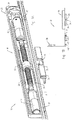
- Fig. 1A shows a part of a fitting arrangement 10 for windows, doors or the like with a frame and with a wing.
- the functioning of the fitting arrangement 10 in connection with a window is described below. It goes without saying, however, that the following explanations also apply in a corresponding manner to other areas of application of the fitting arrangement 10.
- the fitting arrangement 10 comprises sash-side and frame-side components, ie certain components of the fitting arrangement 10 are assigned to the sash of the window, while other components are assigned to the frame.
- a locking bar 12 is provided on the wing side and is arranged displaceably along its longitudinal axis. Depending on the position or functional position of the locking bar 12, the sash of the window can assume different positions, namely a locked position, a tilted position or a position which enables the sash to be opened by rotation.
- the locking bar 12 is covered at least in sections by a faceplate 14 with respect to the exterior of the wing, not shown.
- an actuating mechanism 16 is arranged, which comprises two coaxially arranged motors 18.
- the motors 18 can be operated electrically and, when energized, drive a threaded spindle 20 for a rotary movement, which is converted by means of a spindle nut 22 arranged in a rotationally fixed manner into a linear movement of a driver pin 24 which is fixedly connected to the spindle nut 22 or is formed in one piece.
- the driver pin 24 protrudes through an elongated hole 26 in the locking bar 12.
- the driver pin 24 also passes through Fig. 1A Elongated hole of the faceplate 14 not visible, so that the driver pin 24 projects into the outer space of the window sash, on which the locking bar 12 and the actuating mechanism 16 are arranged.
- the in Fig Fig. 1A Components shown in a - in the use position - lower edge of the window sash, more precisely in a lower, horizontal part of the window sash, arranged.
- Power is supplied via leaf-side and frame-side electrical contacts (not shown) which are in conductive connection when the window sash is arranged in a closed position or in a tilted position relative to the frame receiving the sash.
- leaf-side and frame-side electrical contacts (not shown) which are in conductive connection when the window sash is arranged in a closed position or in a tilted position relative to the frame receiving the sash.
- the electrical contacts are separated from one another, so that in this state the motors 18 are reliably prevented from being actuated unintentionally.
- the spatial arrangement of the actuation mechanism 16 in the lower part of the window sash thus enables the power supply for the motors 18 to be designed in a simple and at the same time secure manner.
- a position determination system 28 which has a potentiometer coupled to a gearwheel 30.
- the gearwheel 30 engages in corresponding recesses 32 in the locking bar 12, so that the gearwheel 30 is set in rotation when the locking bar 12 is moved.
- the potentiometer finally determines the position / position of the locking bar 12 from the measured rotational movement of the gear 30 in a manner known per se.
- Fig. 1A shows in addition to the wing-side components described above, a blocking rail 34 with a release recess 36.
- the function of the components 34, 36 is explained in more detail below.
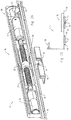
- Figure 1B shows schematically the essential components of the fitting arrangement 10 in the same state as in FIG Fig. 1A .
- the sash of the window is locked in the frame in this state, the driver pin 24 is in a so-called zero position ("to zero position").
- the fitting arrangement 10 has, in addition to the electrically operable actuating mechanism 16, a handle 38 through which the locking bar 12 can also be moved. That is, the locking bar 12 can be moved both by the motors 18 and by the handle 38 in order, for example, to be able to bring the window into a tilted state starting from the closed position shown.
- Figure 1B further shows that the locking bar 12 has a first locking pin 40 and a second locking pin 40 '.
- the locking pin 40 is attached to the frame of the window in the area Bolt receptacle 42 arranged so that opening the wing is not possible.
- the driver pin 24 is on the other hand - as well Fig. 1A it can be seen - in the area of the release recess 36 of the blocking rail 34.
- the wing should be able to be opened even if the power supply to the motors 18 fails.
- the rotary opening position should not be able to be reached via the motors 18, but only manually via the handle 38.
- the fitting arrangement 10 must be designed in such a way that the locking bar 12 can also be displaced without the cooperation of the actuating mechanism 16.
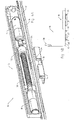
- the fitting arrangement 10 can do this because, as in the 2A and 2B shown, the locking bar 12 is rotatable by turning the handle 38 to the right when moving from the in 1A and 1B shown situation. Since the driver pin 24 in Fig. 1A is arranged at the right end of the elongated hole 26, the locking bar 12 can be moved to the right without the driver pin 24 preventing this movement.
- the driver pin 24 does not move relative to the release recess 36.
- the locking pins 40, 40 ' which are firmly attached to it are also moved to the right, as is the case Figure 2B can be seen.
- the pin 40 is then no longer blocked by the bolt receptacle 42.
- the pin 40 ' also does not stand in the way of opening the wing, since it has not yet been inserted into the bolt receptacle 42.
- the threaded spindle 20 is driven by the motors 18 to a rotary movement, which is converted via the spindle nut 22 into a linear movement of the driver pin 24 to the right. Since the driver pin 24 rests in the “zero position” at the right end of the elongated hole 26, the locking bar 12 is also moved to the right by the movement of the driver pin 24 until the tilting position of the locking bar 12 is reached.
- the locking pin 40 'prevents uncontrolled opening of the window sash in this position.
- the blocking rail 34 in cooperation with the part of the driver pin 24 protruding from the wing, ensures that even when the Figure 2B shown position of the pin 40, 40 'prevents unintentional opening of the window. In this situation, the pins 40, 40 'do not cooperate with the bolt receptacle 42, which is why they cannot have a securing effect. This take over the driver pin 24 and the blocking rail 34.
- the wing is at a transition from that in the Figure 1B position shown to in Figure 4B shown position reliably secured due to the driver pin 24 and the blocking rail 34. An automatic or remote-controlled transition of the window sash from a locked position into a tilted position - and vice versa - is therefore possible without risk.
- the fitting arrangement 10 must be actuated again starting from the "tilt-zero position".
- the motors 18 are activated, as a result of which the driving pin 24 is moved to the left and in the process takes the locking bar 12 with it until it reaches the 5A and 5B shown position is reached. Inadvertent opening of the wing - analogous to the situation described above - is reliably prevented when the locking bar 12 is displaced by the area of the blocking rail 34 arranged on the left of the release recess 36 in cooperation with the driving pin 24.
- the driver pin 24 is automatically moved back into the neutral position, in which the nut 22 is located approximately in the middle of the threaded spindle 20.
- the in the 1A and 1B The situation shown is then reached again and the fitting arrangement 10 is in the “zero position”, which makes it possible to move the locking bar 12 either manually - ie by means of the handle 38 - into the rotary opening position or into the tilting position or through the motors 18 to move to the tilt position.
Claims (13)
- Ensemble de ferrure pour fenêtres, portes ou similaires, comportant un cadre et un battant,
l'ensemble de ferrure comprenant du côté battant une barre de verrouillage (12), un dispositif d'actionnement (38) mécanique actionnable manuellement, et au moins un moteur d'actionnement (18),
dans lequel
la barre de verrouillage (12) est mobile en translation et peut être amenée dans une première et dans une seconde position de fonctionnement aussi bien par le moteur d'actionnement (18) que par le dispositif d'actionnement (38),
le moteur d'actionnement (18) et les composants (20, 22, 24) destinés à coupler en termes d'entraînement le moteur d'actionnement (18) à la barre de verrouillage (12) sont réalisés pour être disposés dans une zone d'un bord du battant, inférieur en position d'utilisation, dans un cadre de battant,
caractérisé en ce que
il est prévu un moyen de pivotement permettant d'amener le battant dans le cadre jusque dans une position pivotée, et le moyen de pivotement est couplé en termes d'entraînement au moteur d'actionnement (18) et/ou au dispositif d'actionnement (38) soit directement soit indirectement par un guidage forcé mécanique, de sorte qu'un actionnement du moteur d'actionnement (18) ou du dispositif d'actionnement (38) provoque non seulement un mouvement de la barre de verrouillage (12) mais également la génération active d'un mouvement de pivotement du battant. - Ensemble de ferrure selon la revendication 1,
caractérisé en ce que
le moteur d'entraînement (18) peut être couplé en termes d'entraînement à la barre de verrouillage via un élément entraîneur mobile en particulier linéairement, la barre de verrouillage comprenant un tenon d'entraînement qui, dans un état couplé en termes d'entraînement, coopère avec l'une de deux surfaces d'entraînement de l'élément entraîneur tournées l'une vers l'autre. - Ensemble de ferrure pour fenêtres, portes ou similaires, comportant un cadre et un battant, selon la revendication 1,
dans lequel
il est prévu un élément entraîneur (24) couplé en termes d'entraînement au moteur d'actionnement (18), réalisé en particulier en forme de tenon et/ou mobile linéairement, qui peut sélectivement être amené en couplage d'entraînement avec la barre de verrouillage (12) et qui traverse la barre de verrouillage (12) de telle sorte que l'élément entraîneur (24) fait saillie hors du battant dans un état monté de l'ensemble de ferrure. - Ensemble de ferrure selon l'une des revendications précédentes,
caractérisé en ce que
une unité de commande est associée au moteur d'entraînement (18), laquelle est conçue de telle sorte que l'élément entraîneur (24) peut être amené dans une première position, dans une seconde position et dans une position neutre, la position neutre se situant en particulier entre la première et la seconde position et l'unité de commande étant conçue en particulier de telle sorte que l'élément entraîneur (24) est automatiquement déplaçable jusque dans la position neutre après avoir atteint la première ou la seconde position. - Ensemble de ferrure selon l'une au moins des revendications précédentes,
caractérisé en ce que
l'élément entraîneur (24) peut être couplé à la barre de verrouillage (12) de telle sorte qu'un déplacement de l'élément entraîneur (24) jusque dans la première position provoque une translation de la barre de verrouillage (12) dans la première position de fonctionnement, et qu'un déplacement de l'élément entraîneur (24) jusque dans la seconde position provoque une translation de la barre de verrouillage (12) dans la seconde position de fonctionnement. - Ensemble de ferrure selon l'une au moins des revendications précédentes,
caractérisé en ce que
la barre de verrouillage (12) peut être amenée dans une troisième position de fonctionnement qui se situe entre la première et la seconde position de fonctionnement, la barre de verrouillage (12) et l'élément entraîneur (24) étant en particulier conçus de telle sorte que la barre de verrouillage (12) peut être amenée dans la troisième position de fonctionnement par un actionnement du dispositif d'actionnement (38) sans contribution de l'élément entraîneur (24). - Ensemble de ferrure selon l'une au moins des revendications 2 à 6,
caractérisé en ce que
la barre de verrouillage (12) présente un trou oblong (26) traversé par l'élément entraîneur (24), et en particulier la longueur du trou oblong (26) en direction longitudinale de la barre de verrouillage (12) correspond - en prenant en compte l'extension de l'élément entraîneur (24) dans cette direction - au trajet qui est requis pour translater la barre de verrouillage (12) depuis la première position de fonctionnement jusque dans la seconde position de fonctionnement. - Ensemble de ferrure selon l'une au moins des revendications précédentes,
caractérisé en ce que
le moteur d'actionnement (18) est couplé en termes d'entraînement à une broche filetée (20), la broche filetée (20) étant en liaison d'entraînement avec l'élément entraîneur (24) en particulier par un écrou de broche (22), et/ou en ce que
il est prévu deux moteurs d'actionnement (18) qui sont agencés en particulier coaxialement. - Ensemble de ferrure selon l'une au moins des revendications précédentes,
caractérisé en ce que
la barre de verrouillage (12) est agencée entre le moteur d'actionnement (18) et une têtière (14) qui recouvre au moins localement la barre de verrouillage (12) par rapport à l'espace extérieur du battant et qui est traversée par l'élément entraîneur (24). - Ensemble de ferrure selon l'une au moins des revendications précédentes,
caractérisé en ce que
l'ensemble de ferrure comprend un moyen de détermination de position (28) pour déterminer la position de la barre de verrouillage (12), et en particulier le moyen de détermination de position (28) comprend un capteur d'angle de rotation, en particulier un potentiomètre, qui est couplé à la barre de verrouillage (12) par une roue dentée (30) qui vient s'engager dans des évidements (32) de la barre de verrouillage (12). - Ensemble de ferrure selon l'une au moins des revendications précédentes,
caractérisé en ce que
l'ensemble de ferrure comprend du côté cadre un mécanisme de blocage (24, 34) permettant de bloquer le battant pendant la translation de la barre de verrouillage (12) depuis la première jusque dans la seconde position de fonctionnement, et en particulier le mécanisme de blocage (24, 34) présente un moyen de libération (36) qui est conçu de telle sorte que le mécanisme de blocage (24, 34) ne coopère pas avec l'élément entraîneur (24) dans une position neutre de ce dernier, et/ou le mécanisme de blocage (24, 34) comprend un rail (34) avec lequel coopère l'élément entraîneur (24) pendant la translation. - Ensemble de ferrure selon l'une au moins des revendications précédentes,
caractérisé en ce que
la barre de verrouillage (12) est pourvue d'au moins un tenon de verrouillage (40, 40') qui, dans la première et/ou dans la seconde position de fonctionnement de la barre de verrouillage (12), coopère avec un moyen de verrouillage (42) côté cadre de l'ensemble de ferrure, et en particulier la barre de verrouillage (12) est pourvue d'un premier tenon de verrouillage (40) et d'un second tenon de verrouillage (40') qui sont espacés l'un de l'autre, le premier tenon de verrouillage (40) coopérant avec le moyen de verrouillage (42) dans la première position de fonctionnement de la barre de verrouillage (12), et le second tenon de verrouillage (40') coopérant avec le moyen de verrouillage (42) dans la seconde position de fonctionnement de la barre de verrouillage (12), le moyen de verrouillage étant de préférence un logement de verrouillage (42) dont l'extension longitudinale est plus courte que la distance entre le premier et le second tenon de verrouillage (40, 40'). - Fenêtre, porte ou similaires, comportant un cadre, un battant et un ensemble de ferrure selon l'une au moins des revendications 1 à 12.
Priority Applications (1)
| Application Number | Priority Date | Filing Date | Title |
|---|---|---|---|
| PL18179199T PL3401475T3 (pl) | 2012-02-13 | 2013-02-07 | Zespół okucia |
Applications Claiming Priority (2)
| Application Number | Priority Date | Filing Date | Title |
|---|---|---|---|
| DE202012001475U DE202012001475U1 (de) | 2012-02-13 | 2012-02-13 | Beschlaganordnung |
| EP13154435.5A EP2626491B1 (fr) | 2012-02-13 | 2013-02-07 | Agencement de ferrure |
Related Parent Applications (2)
| Application Number | Title | Priority Date | Filing Date |
|---|---|---|---|
| EP13154435.5A Division EP2626491B1 (fr) | 2012-02-13 | 2013-02-07 | Agencement de ferrure |
| EP13154435.5A Division-Into EP2626491B1 (fr) | 2012-02-13 | 2013-02-07 | Agencement de ferrure |
Publications (2)
| Publication Number | Publication Date |
|---|---|
| EP3401475A1 EP3401475A1 (fr) | 2018-11-14 |
| EP3401475B1 true EP3401475B1 (fr) | 2020-04-29 |
Family
ID=47722051
Family Applications (2)
| Application Number | Title | Priority Date | Filing Date |
|---|---|---|---|
| EP13154435.5A Active EP2626491B1 (fr) | 2012-02-13 | 2013-02-07 | Agencement de ferrure |
| EP18179199.7A Active EP3401475B1 (fr) | 2012-02-13 | 2013-02-07 | Système d'armatures |
Family Applications Before (1)
| Application Number | Title | Priority Date | Filing Date |
|---|---|---|---|
| EP13154435.5A Active EP2626491B1 (fr) | 2012-02-13 | 2013-02-07 | Agencement de ferrure |
Country Status (3)
| Country | Link |
|---|---|
| EP (2) | EP2626491B1 (fr) |
| DE (1) | DE202012001475U1 (fr) |
| PL (2) | PL2626491T3 (fr) |
Families Citing this family (6)
| Publication number | Priority date | Publication date | Assignee | Title |
|---|---|---|---|---|
| DE102012214003A1 (de) * | 2012-08-07 | 2014-02-13 | Brose Fahrzeugteile Gmbh & Co. Kg, Coburg | Schließvorrichtung für eine Gebäudeöffnung |
| FR3005326B1 (fr) | 2013-05-02 | 2015-06-05 | Hydro Building Systems | Dispositif motorise de verrouillage/deverrouillage d'un ouvrant, notamment d'une fenetre |
| DE202017107392U1 (de) | 2016-12-08 | 2018-03-09 | Maco Technologie Gmbh | Schiebe-Element |
| DE202019100744U1 (de) | 2019-02-08 | 2020-05-11 | Aumüller Aumatic GmbH | Kippantriebsvorrichtung für einen Flügel |
| DE102019105034A1 (de) * | 2019-02-27 | 2020-08-27 | Gröninger Antriebstechnik GmbH & Co. KG | Tür- oder Fensteranordnung mit einer Antriebseinheit im Blendrahmen |
| US11905751B2 (en) * | 2022-04-21 | 2024-02-20 | ABT Systems, LLC | Housing for mounting and adjusting the alignment of a window actuator |
Family Cites Families (11)
| Publication number | Priority date | Publication date | Assignee | Title |
|---|---|---|---|---|
| DE3812675C2 (de) * | 1988-04-18 | 1997-06-19 | Horst Grimm Fa | Türe für ein Transportkraftfahrzeug |
| DE19603770A1 (de) * | 1996-02-02 | 1997-08-07 | Winkhaus Fa August | Fenster, Tür oder dergleichen mit Beschlagsystem |
| EP1243728B1 (fr) * | 2001-03-20 | 2005-06-15 | SCHÜCO International KG | Unité d'entraínement pour fenêtres ou portes |
| DE10139675A1 (de) * | 2001-08-11 | 2003-02-20 | Winkhaus Fa August | Verriegelungseinrichtung |
| DE20204224U1 (de) | 2002-03-16 | 2002-05-23 | Winkhaus Fa August | Vorrichtung zum Ausstellen und Verriegeln eines an einem Rahmen schwenkbar angeordneten Flügels |
| EP1405973B1 (fr) * | 2002-10-01 | 2007-10-10 | Somfy S.A.S. | Mécanisme de verrouillage pour fenêtre ou porte oscillobattante |
| ATE312991T1 (de) * | 2003-02-19 | 2005-12-15 | Roto Frank Ag | Fenster, tür oder dergleichen mit einer motorischen antriebseinheit für eine treibstangenanordnung |
| DE10308243B4 (de) * | 2003-02-25 | 2006-11-02 | Carl Fuhr Gmbh & Co. Kg | Schließanlage, insbesondere Türverschluss, Fensterverschluss oder dergleichen |
| DE10346883A1 (de) * | 2003-10-09 | 2005-05-04 | Winkhaus Fa August | Antriebseinrichtung für einen Treibstangenbeschlag |
| DE102004015147A1 (de) | 2004-03-27 | 2005-10-13 | Aug. Winkhaus Gmbh & Co. Kg | Antriebseinrichtung |
| KR101023954B1 (ko) * | 2006-10-23 | 2011-03-28 | (주)엘지하우시스 | 전동방식에 의한 창호의 리프트 및 슬라이드 장치 |
-
2012
- 2012-02-13 DE DE202012001475U patent/DE202012001475U1/de not_active Expired - Lifetime
-
2013
- 2013-02-07 PL PL13154435T patent/PL2626491T3/pl unknown
- 2013-02-07 EP EP13154435.5A patent/EP2626491B1/fr active Active
- 2013-02-07 EP EP18179199.7A patent/EP3401475B1/fr active Active
- 2013-02-07 PL PL18179199T patent/PL3401475T3/pl unknown
Non-Patent Citations (1)
| Title |
|---|
| None * |
Also Published As
| Publication number | Publication date |
|---|---|
| PL2626491T3 (pl) | 2019-05-31 |
| PL3401475T3 (pl) | 2020-11-30 |
| DE202012001475U1 (de) | 2013-05-15 |
| EP2626491A2 (fr) | 2013-08-14 |
| EP2626491B1 (fr) | 2018-09-12 |
| EP2626491A3 (fr) | 2016-12-21 |
| EP3401475A1 (fr) | 2018-11-14 |
Similar Documents
| Publication | Publication Date | Title |
|---|---|---|
| EP3401475B1 (fr) | Système d'armatures | |
| EP3612696B1 (fr) | Ensemble de poignée de porte pour un véhicule | |
| EP2320016A1 (fr) | Dispositif de commande verticale pour un battant coulissant de levage | |
| EP2206862A2 (fr) | Engrenage de languettes destiné au verrouillage ou au déverrouillage d'un volet coulissant | |
| DE4321099A1 (de) | Belüftungseinrichtung für Fenster oder Türen | |
| EP2146032A1 (fr) | Dispositif destiné à ouvrir et/ou fermer ainsi qu'à verrouiller un état fermé d'un dispositif de fermeture destiné à fermer une ouverture de salle ainsi que dispositif de fermeture doté d'un tel dispositif | |
| EP2520746B1 (fr) | Serrure actionnée de manière électrique | |
| EP2169156B1 (fr) | Serrure à mortaiser sans pêne dormant | |
| EP1865130A1 (fr) | Agencement de déverrouillage d'une fenêtre, d'une porte ou analogue | |
| EP3045624A1 (fr) | Dispositif de verrouillage d'un battant pivotant | |
| WO2023143823A1 (fr) | Dispositif de déplacement pour le déplacement forcé d'un battant, en particulier d'un battant coulissant, d'une fenêtre ou d'une porte | |
| DE10308243B4 (de) | Schließanlage, insbesondere Türverschluss, Fensterverschluss oder dergleichen | |
| DE19900875C2 (de) | Verriegelungsvorrichtung für eine Türanlage | |
| EP1255905A1 (fr) | Dispositif d'actionnement | |
| EP3662123B1 (fr) | Serrure motorisée | |
| DE10257688A1 (de) | Verschussvorrichtung für eine in einem Fahrzeug vorgesehene Öffnung mit einer einzigen Gleitführungsschiene sowie entsprechendes Fahrzeug | |
| DE10038867B4 (de) | Türanlage mit Verriegelungsvorrichtung | |
| EP2453086B1 (fr) | Ferrure de crémone pour battant fixe de fenêtres ou de portes à deux vantaux sans montant médian | |
| EP1344883B1 (fr) | Dispositif de verrouillage pour une porte | |
| EP1990492A2 (fr) | Serrure motorisée de verrouillage à plusieurs points | |
| EP1790805B1 (fr) | Mécanisme d'actionnement à levier pour une crémone | |
| EP1816291A2 (fr) | Dispositif d'entraînement pour un vantail pouvant être encliqueté dans un cadre de fenêtre | |
| DE3221110A1 (de) | Beschlag fuer einen kipp- und nachfolgend mindestens parallelabstellbaren fluegel eines fensters, einer tuer od. dgl. | |
| EP3702555B1 (fr) | Agencement de porte ou de fenêtre doté d'une unité d'entraînement dans le bâti dormant | |
| EP0668426A1 (fr) | Ferrure pour fenêtres ou portes |
Legal Events
| Date | Code | Title | Description |
|---|---|---|---|
| PUAI | Public reference made under article 153(3) epc to a published international application that has entered the european phase |
Free format text: ORIGINAL CODE: 0009012 |
|
| STAA | Information on the status of an ep patent application or granted ep patent |
Free format text: STATUS: THE APPLICATION HAS BEEN PUBLISHED |
|
| AC | Divisional application: reference to earlier application |
Ref document number: 2626491 Country of ref document: EP Kind code of ref document: P |
|
| AK | Designated contracting states |
Kind code of ref document: A1 Designated state(s): AL AT BE BG CH CY CZ DE DK EE ES FI FR GB GR HR HU IE IS IT LI LT LU LV MC MK MT NL NO PL PT RO RS SE SI SK SM TR |
|
| STAA | Information on the status of an ep patent application or granted ep patent |
Free format text: STATUS: REQUEST FOR EXAMINATION WAS MADE |
|
| 17P | Request for examination filed |
Effective date: 20190424 |
|
| RBV | Designated contracting states (corrected) |
Designated state(s): AL AT BE BG CH CY CZ DE DK EE ES FI FR GB GR HR HU IE IS IT LI LT LU LV MC MK MT NL NO PL PT RO RS SE SI SK SM TR |
|
| RIC1 | Information provided on ipc code assigned before grant |
Ipc: E05C 9/08 20060101AFI20190913BHEP Ipc: E05B 47/02 20060101ALI20190913BHEP Ipc: E05D 15/52 20060101ALI20190913BHEP Ipc: E05C 9/00 20060101ALI20190913BHEP Ipc: E05B 47/00 20060101ALI20190913BHEP |
|
| GRAP | Despatch of communication of intention to grant a patent |
Free format text: ORIGINAL CODE: EPIDOSNIGR1 |
|
| STAA | Information on the status of an ep patent application or granted ep patent |
Free format text: STATUS: GRANT OF PATENT IS INTENDED |
|
| INTG | Intention to grant announced |
Effective date: 20191115 |
|
| GRAS | Grant fee paid |
Free format text: ORIGINAL CODE: EPIDOSNIGR3 |
|
| GRAA | (expected) grant |
Free format text: ORIGINAL CODE: 0009210 |
|
| STAA | Information on the status of an ep patent application or granted ep patent |
Free format text: STATUS: THE PATENT HAS BEEN GRANTED |
|
| AC | Divisional application: reference to earlier application |
Ref document number: 2626491 Country of ref document: EP Kind code of ref document: P |
|
| AK | Designated contracting states |
Kind code of ref document: B1 Designated state(s): AL AT BE BG CH CY CZ DE DK EE ES FI FR GB GR HR HU IE IS IT LI LT LU LV MC MK MT NL NO PL PT RO RS SE SI SK SM TR |
|
| REG | Reference to a national code |
Ref country code: GB Ref legal event code: FG4D Free format text: NOT ENGLISH |
|
| REG | Reference to a national code |
Ref country code: CH Ref legal event code: EP |
|
| REG | Reference to a national code |
Ref country code: AT Ref legal event code: REF Ref document number: 1263536 Country of ref document: AT Kind code of ref document: T Effective date: 20200515 |
|
| REG | Reference to a national code |
Ref country code: DE Ref legal event code: R096 Ref document number: 502013014672 Country of ref document: DE |
|
| REG | Reference to a national code |
Ref country code: IE Ref legal event code: FG4D Free format text: LANGUAGE OF EP DOCUMENT: GERMAN |
|
| REG | Reference to a national code |
Ref country code: NL Ref legal event code: MP Effective date: 20200429 |
|
| REG | Reference to a national code |
Ref country code: LT Ref legal event code: MG4D |
|
| PG25 | Lapsed in a contracting state [announced via postgrant information from national office to epo] |
Ref country code: LT Free format text: LAPSE BECAUSE OF FAILURE TO SUBMIT A TRANSLATION OF THE DESCRIPTION OR TO PAY THE FEE WITHIN THE PRESCRIBED TIME-LIMIT Effective date: 20200429 Ref country code: FI Free format text: LAPSE BECAUSE OF FAILURE TO SUBMIT A TRANSLATION OF THE DESCRIPTION OR TO PAY THE FEE WITHIN THE PRESCRIBED TIME-LIMIT Effective date: 20200429 Ref country code: NO Free format text: LAPSE BECAUSE OF FAILURE TO SUBMIT A TRANSLATION OF THE DESCRIPTION OR TO PAY THE FEE WITHIN THE PRESCRIBED TIME-LIMIT Effective date: 20200729 Ref country code: SE Free format text: LAPSE BECAUSE OF FAILURE TO SUBMIT A TRANSLATION OF THE DESCRIPTION OR TO PAY THE FEE WITHIN THE PRESCRIBED TIME-LIMIT Effective date: 20200429 Ref country code: PT Free format text: LAPSE BECAUSE OF FAILURE TO SUBMIT A TRANSLATION OF THE DESCRIPTION OR TO PAY THE FEE WITHIN THE PRESCRIBED TIME-LIMIT Effective date: 20200831 Ref country code: IS Free format text: LAPSE BECAUSE OF FAILURE TO SUBMIT A TRANSLATION OF THE DESCRIPTION OR TO PAY THE FEE WITHIN THE PRESCRIBED TIME-LIMIT Effective date: 20200829 Ref country code: GR Free format text: LAPSE BECAUSE OF FAILURE TO SUBMIT A TRANSLATION OF THE DESCRIPTION OR TO PAY THE FEE WITHIN THE PRESCRIBED TIME-LIMIT Effective date: 20200730 |
|
| PG25 | Lapsed in a contracting state [announced via postgrant information from national office to epo] |
Ref country code: BG Free format text: LAPSE BECAUSE OF FAILURE TO SUBMIT A TRANSLATION OF THE DESCRIPTION OR TO PAY THE FEE WITHIN THE PRESCRIBED TIME-LIMIT Effective date: 20200729 Ref country code: RS Free format text: LAPSE BECAUSE OF FAILURE TO SUBMIT A TRANSLATION OF THE DESCRIPTION OR TO PAY THE FEE WITHIN THE PRESCRIBED TIME-LIMIT Effective date: 20200429 Ref country code: HR Free format text: LAPSE BECAUSE OF FAILURE TO SUBMIT A TRANSLATION OF THE DESCRIPTION OR TO PAY THE FEE WITHIN THE PRESCRIBED TIME-LIMIT Effective date: 20200429 Ref country code: LV Free format text: LAPSE BECAUSE OF FAILURE TO SUBMIT A TRANSLATION OF THE DESCRIPTION OR TO PAY THE FEE WITHIN THE PRESCRIBED TIME-LIMIT Effective date: 20200429 |
|
| PG25 | Lapsed in a contracting state [announced via postgrant information from national office to epo] |
Ref country code: AL Free format text: LAPSE BECAUSE OF FAILURE TO SUBMIT A TRANSLATION OF THE DESCRIPTION OR TO PAY THE FEE WITHIN THE PRESCRIBED TIME-LIMIT Effective date: 20200429 Ref country code: NL Free format text: LAPSE BECAUSE OF FAILURE TO SUBMIT A TRANSLATION OF THE DESCRIPTION OR TO PAY THE FEE WITHIN THE PRESCRIBED TIME-LIMIT Effective date: 20200429 |
|
| PG25 | Lapsed in a contracting state [announced via postgrant information from national office to epo] |
Ref country code: RO Free format text: LAPSE BECAUSE OF FAILURE TO SUBMIT A TRANSLATION OF THE DESCRIPTION OR TO PAY THE FEE WITHIN THE PRESCRIBED TIME-LIMIT Effective date: 20200429 Ref country code: CZ Free format text: LAPSE BECAUSE OF FAILURE TO SUBMIT A TRANSLATION OF THE DESCRIPTION OR TO PAY THE FEE WITHIN THE PRESCRIBED TIME-LIMIT Effective date: 20200429 Ref country code: ES Free format text: LAPSE BECAUSE OF FAILURE TO SUBMIT A TRANSLATION OF THE DESCRIPTION OR TO PAY THE FEE WITHIN THE PRESCRIBED TIME-LIMIT Effective date: 20200429 Ref country code: DK Free format text: LAPSE BECAUSE OF FAILURE TO SUBMIT A TRANSLATION OF THE DESCRIPTION OR TO PAY THE FEE WITHIN THE PRESCRIBED TIME-LIMIT Effective date: 20200429 Ref country code: SM Free format text: LAPSE BECAUSE OF FAILURE TO SUBMIT A TRANSLATION OF THE DESCRIPTION OR TO PAY THE FEE WITHIN THE PRESCRIBED TIME-LIMIT Effective date: 20200429 Ref country code: EE Free format text: LAPSE BECAUSE OF FAILURE TO SUBMIT A TRANSLATION OF THE DESCRIPTION OR TO PAY THE FEE WITHIN THE PRESCRIBED TIME-LIMIT Effective date: 20200429 |
|
| REG | Reference to a national code |
Ref country code: DE Ref legal event code: R097 Ref document number: 502013014672 Country of ref document: DE |
|
| PG25 | Lapsed in a contracting state [announced via postgrant information from national office to epo] |
Ref country code: SK Free format text: LAPSE BECAUSE OF FAILURE TO SUBMIT A TRANSLATION OF THE DESCRIPTION OR TO PAY THE FEE WITHIN THE PRESCRIBED TIME-LIMIT Effective date: 20200429 |
|
| PLBE | No opposition filed within time limit |
Free format text: ORIGINAL CODE: 0009261 |
|
| STAA | Information on the status of an ep patent application or granted ep patent |
Free format text: STATUS: NO OPPOSITION FILED WITHIN TIME LIMIT |
|
| 26N | No opposition filed |
Effective date: 20210201 |
|
| PG25 | Lapsed in a contracting state [announced via postgrant information from national office to epo] |
Ref country code: SI Free format text: LAPSE BECAUSE OF FAILURE TO SUBMIT A TRANSLATION OF THE DESCRIPTION OR TO PAY THE FEE WITHIN THE PRESCRIBED TIME-LIMIT Effective date: 20200429 |
|
| PG25 | Lapsed in a contracting state [announced via postgrant information from national office to epo] |
Ref country code: MC Free format text: LAPSE BECAUSE OF FAILURE TO SUBMIT A TRANSLATION OF THE DESCRIPTION OR TO PAY THE FEE WITHIN THE PRESCRIBED TIME-LIMIT Effective date: 20200429 |
|
| GBPC | Gb: european patent ceased through non-payment of renewal fee |
Effective date: 20210207 |
|
| REG | Reference to a national code |
Ref country code: BE Ref legal event code: MM Effective date: 20210228 |
|
| PG25 | Lapsed in a contracting state [announced via postgrant information from national office to epo] |
Ref country code: LU Free format text: LAPSE BECAUSE OF NON-PAYMENT OF DUE FEES Effective date: 20210207 Ref country code: LI Free format text: LAPSE BECAUSE OF NON-PAYMENT OF DUE FEES Effective date: 20210228 Ref country code: CH Free format text: LAPSE BECAUSE OF NON-PAYMENT OF DUE FEES Effective date: 20210228 |
|
| PG25 | Lapsed in a contracting state [announced via postgrant information from national office to epo] |
Ref country code: GB Free format text: LAPSE BECAUSE OF NON-PAYMENT OF DUE FEES Effective date: 20210207 Ref country code: FR Free format text: LAPSE BECAUSE OF NON-PAYMENT OF DUE FEES Effective date: 20210228 Ref country code: IE Free format text: LAPSE BECAUSE OF NON-PAYMENT OF DUE FEES Effective date: 20210207 |
|
| PG25 | Lapsed in a contracting state [announced via postgrant information from national office to epo] |
Ref country code: BE Free format text: LAPSE BECAUSE OF NON-PAYMENT OF DUE FEES Effective date: 20210228 |
|
| PGFP | Annual fee paid to national office [announced via postgrant information from national office to epo] |
Ref country code: AT Payment date: 20230217 Year of fee payment: 11 |
|
| PGFP | Annual fee paid to national office [announced via postgrant information from national office to epo] |
Ref country code: PL Payment date: 20230127 Year of fee payment: 11 Ref country code: IT Payment date: 20230223 Year of fee payment: 11 Ref country code: DE Payment date: 20230216 Year of fee payment: 11 |
|
| PG25 | Lapsed in a contracting state [announced via postgrant information from national office to epo] |
Ref country code: CY Free format text: LAPSE BECAUSE OF FAILURE TO SUBMIT A TRANSLATION OF THE DESCRIPTION OR TO PAY THE FEE WITHIN THE PRESCRIBED TIME-LIMIT Effective date: 20200429 |
|
| PG25 | Lapsed in a contracting state [announced via postgrant information from national office to epo] |
Ref country code: HU Free format text: LAPSE BECAUSE OF FAILURE TO SUBMIT A TRANSLATION OF THE DESCRIPTION OR TO PAY THE FEE WITHIN THE PRESCRIBED TIME-LIMIT; INVALID AB INITIO Effective date: 20130207 |
|
| PGFP | Annual fee paid to national office [announced via postgrant information from national office to epo] |
Ref country code: AT Payment date: 20240220 Year of fee payment: 12 |