EP3401475B1 - Fitting device - Google Patents
Fitting device Download PDFInfo
- Publication number
- EP3401475B1 EP3401475B1 EP18179199.7A EP18179199A EP3401475B1 EP 3401475 B1 EP3401475 B1 EP 3401475B1 EP 18179199 A EP18179199 A EP 18179199A EP 3401475 B1 EP3401475 B1 EP 3401475B1
- Authority
- EP
- European Patent Office
- Prior art keywords
- locking bar
- fitting arrangement
- locking
- entrainment element
- actuation
- Prior art date
- Legal status (The legal status is an assumption and is not a legal conclusion. Google has not performed a legal analysis and makes no representation as to the accuracy of the status listed.)
- Active
Links
Images


Classifications
-
- E—FIXED CONSTRUCTIONS
- E05—LOCKS; KEYS; WINDOW OR DOOR FITTINGS; SAFES
- E05D—HINGES OR SUSPENSION DEVICES FOR DOORS, WINDOWS OR WINGS
- E05D15/00—Suspension arrangements for wings
- E05D15/48—Suspension arrangements for wings allowing alternative movements
- E05D15/52—Suspension arrangements for wings allowing alternative movements for opening about a vertical as well as a horizontal axis
-
- E—FIXED CONSTRUCTIONS
- E05—LOCKS; KEYS; WINDOW OR DOOR FITTINGS; SAFES
- E05B—LOCKS; ACCESSORIES THEREFOR; HANDCUFFS
- E05B47/00—Operating or controlling locks or other fastening devices by electric or magnetic means
- E05B47/02—Movement of the bolt by electromagnetic means; Adaptation of locks, latches, or parts thereof, for movement of the bolt by electromagnetic means
- E05B47/026—Movement of the bolt by electromagnetic means; Adaptation of locks, latches, or parts thereof, for movement of the bolt by electromagnetic means the bolt moving rectilinearly
-
- E—FIXED CONSTRUCTIONS
- E05—LOCKS; KEYS; WINDOW OR DOOR FITTINGS; SAFES
- E05C—BOLTS OR FASTENING DEVICES FOR WINGS, SPECIALLY FOR DOORS OR WINDOWS
- E05C9/00—Arrangements of simultaneously actuated bolts or other securing devices at well-separated positions on the same wing
-
- E—FIXED CONSTRUCTIONS
- E05—LOCKS; KEYS; WINDOW OR DOOR FITTINGS; SAFES
- E05F—DEVICES FOR MOVING WINGS INTO OPEN OR CLOSED POSITION; CHECKS FOR WINGS; WING FITTINGS NOT OTHERWISE PROVIDED FOR, CONCERNED WITH THE FUNCTIONING OF THE WING
- E05F15/00—Power-operated mechanisms for wings
- E05F15/60—Power-operated mechanisms for wings using electrical actuators
- E05F15/603—Power-operated mechanisms for wings using electrical actuators using rotary electromotors
- E05F15/611—Power-operated mechanisms for wings using electrical actuators using rotary electromotors for swinging wings
-
- E—FIXED CONSTRUCTIONS
- E05—LOCKS; KEYS; WINDOW OR DOOR FITTINGS; SAFES
- E05B—LOCKS; ACCESSORIES THEREFOR; HANDCUFFS
- E05B47/00—Operating or controlling locks or other fastening devices by electric or magnetic means
- E05B47/0001—Operating or controlling locks or other fastening devices by electric or magnetic means with electric actuators; Constructional features thereof
- E05B47/0012—Operating or controlling locks or other fastening devices by electric or magnetic means with electric actuators; Constructional features thereof with rotary electromotors
- E05B2047/0013—Operating or controlling locks or other fastening devices by electric or magnetic means with electric actuators; Constructional features thereof with rotary electromotors more than one motor for the same function, e.g. for redundancy or increased power
-
- E—FIXED CONSTRUCTIONS
- E05—LOCKS; KEYS; WINDOW OR DOOR FITTINGS; SAFES
- E05B—LOCKS; ACCESSORIES THEREFOR; HANDCUFFS
- E05B47/00—Operating or controlling locks or other fastening devices by electric or magnetic means
- E05B47/0001—Operating or controlling locks or other fastening devices by electric or magnetic means with electric actuators; Constructional features thereof
- E05B2047/0014—Constructional features of actuators or power transmissions therefor
- E05B2047/0018—Details of actuator transmissions
- E05B2047/0023—Nuts or nut-like elements moving along a driven threaded axle
-
- E—FIXED CONSTRUCTIONS
- E05—LOCKS; KEYS; WINDOW OR DOOR FITTINGS; SAFES
- E05B—LOCKS; ACCESSORIES THEREFOR; HANDCUFFS
- E05B47/00—Operating or controlling locks or other fastening devices by electric or magnetic means
- E05B2047/0048—Circuits, feeding, monitoring
- E05B2047/0067—Monitoring
-
- E—FIXED CONSTRUCTIONS
- E05—LOCKS; KEYS; WINDOW OR DOOR FITTINGS; SAFES
- E05Y—INDEXING SCHEME RELATING TO HINGES OR OTHER SUSPENSION DEVICES FOR DOORS, WINDOWS OR WINGS AND DEVICES FOR MOVING WINGS INTO OPEN OR CLOSED POSITION, CHECKS FOR WINGS AND WING FITTINGS NOT OTHERWISE PROVIDED FOR, CONCERNED WITH THE FUNCTIONING OF THE WING
- E05Y2600/00—Mounting or coupling arrangements for elements provided for in this subclass
- E05Y2600/40—Mounting location; Visibility of the elements
- E05Y2600/46—Mounting location; Visibility of the elements in or on the wing
-
- E—FIXED CONSTRUCTIONS
- E05—LOCKS; KEYS; WINDOW OR DOOR FITTINGS; SAFES
- E05Y—INDEXING SCHEME RELATING TO HINGES OR OTHER SUSPENSION DEVICES FOR DOORS, WINDOWS OR WINGS AND DEVICES FOR MOVING WINGS INTO OPEN OR CLOSED POSITION, CHECKS FOR WINGS AND WING FITTINGS NOT OTHERWISE PROVIDED FOR, CONCERNED WITH THE FUNCTIONING OF THE WING
- E05Y2900/00—Application of doors, windows, wings or fittings thereof
- E05Y2900/10—Application of doors, windows, wings or fittings thereof for buildings or parts thereof
- E05Y2900/13—Application of doors, windows, wings or fittings thereof for buildings or parts thereof characterised by the type of wing
- E05Y2900/148—Windows
Definitions
- the present invention relates to a fitting arrangement for windows, doors or the like with a frame and with a wing, the fitting arrangement comprising on the wing side a locking bar, a mechanical - in particular manually operated - actuating device and at least one actuating motor.
- the fitting arrangement can optionally be operated by the actuating motor and the actuating device, i.e. the locking bar is displaceable and can be brought into a first and a second functional position both by the actuating motor and by the actuating device.
- Such motor-driven fitting arrangements increase ease of use and, for example, also enable remote-controlled actuation, e.g. to bring the wing in the frame from a closed position to a tilted position - and vice versa.
- the DE 196 03 770 A1 discloses a fitting arrangement with the features of the respective preamble of the independent claims.
- the actuating motor and components for drivingly coupling the actuating motor to the locking bar are designed to be arranged in a region of a lower edge of the wing, in the position of use.
- the actuating motor and the components mentioned are designed to be arranged in a region of a lower edge of a casement, for example in a window frame.
- This design is accompanied by the advantage that the energy required for actuating the fitting arrangement by the actuating motor can be supplied in a simple manner, since no complex wiring for power supply is required even when the sash is tilted. In this state, too, the lower edge of the wing is in close spatial contact with the frame assigned to the wing, so that corresponding electrical contacts can be designed to be comparatively simple.
- the actuating motor can be coupled to the locking rod in a drive-effective manner via a driver element, the locking rod having a drive pin which, in a drive-effectively coupled state, interacts with one of two mutually facing drive surfaces of the driver element which can be moved by the actuating motor.
- the driver element in this embodiment - figuratively speaking - is designed as a flat U-profile, the inner sides of the legs of the U-profile forming the drive surfaces. By moving the U-profile laterally, either one or the other inside of the U-profile can come into contact with the drive pin brought in order to be able to move it - and thus also the locking bar.
- the section of the U-profile connecting the legs defines the path that the driver element has to travel in order to move from a coupling with one of the drive surfaces to a coupling with the other drive surface.
- the section connecting the legs thus defines a kind of "idling between two drive-coupled states, in which a movement of the driver element is transmitted via the corresponding drive surface to the drive pin and thus ultimately to the locking bar.
- the actuating motor is assigned a pin-like driver element
- the locking bar comprises two drive surfaces, for example two lugs, a U-shaped coupling element, a recess and / or an opening between and into which the pin-like driver element intervenes.
- a driver element which is coupled to the actuating motor in a drive-effective manner, in particular in the form of a pin, is provided, which can be selectively brought into a drive-effective coupling with the locking bar and which engages through the locking bar so that the driver element protrudes from the wing.
- the driver element can not only be provided for driving the locking bar, but can also perform additional functions which are useful for reliable operation of the fitting arrangement.
- the driver element can be moved linearly.
- a control unit can be assigned to the actuating motor, which is designed such that the driver element is in a first position, in a second position and can be brought into a neutral position, the neutral position being in particular between the first and the second position.
- the control unit is designed in such a way that only the above-mentioned discrete positions can be taken and the taking of further intermediate positions is not provided.
- the control unit can be designed in such a way that the driver element can automatically be moved into the neutral position after reaching the first and the second position, so that the driver element is always brought back into a well-defined basic or neutral position by a method in the first or the second position.
- the driver element can be coupled to the locking bar in such a way that moving the driver element into the first position causes the locking bar to be moved into the first functional position and that moving the driving element into the second position causes the locking bar to be moved into the second functional position.
- the locking bar can be brought into a third functional position, which lies between the first and the second functional position. It is particularly advantageous if the locking bar and the driver element are configured such that the locking bar can be brought into the third functional position by actuating the actuating device without the driver element participating. In other words, the locking bar should also and in particular only be able to be brought into the third functional position without the cooperation of the actuating motor.
- the first functional position of the locking bar defines a locking position of the fitting arrangement, in which the sash is locked in the frame.
- the second functional position defines a tilt position of the Fitting arrangement in which the sash can be tilted in the frame.
- the third functional position can define a rotational position of the fitting arrangement, in which the sash can be moved in the frame by rotation, ie can be opened in the usual way.
- the length of the elongated hole in the longitudinal direction of the locking bar can - taking into account the expansion of the driver element in this direction - correspond to the distance required to move the locking bar from the first functional position into the second functional position. If the driver element is moved back into the neutral position after the method in one of the two positions, the configuration described above causes the driver element in the neutral position to be arranged again in the region of one of the ends of the elongated hole or even to strike the end. If a different functional position is to be assumed based on this situation, an actuation of the actuating motor and a corresponding movement of the driver element are immediately converted into a movement of the locking bar.
- the actuating motor is coupled to a threaded spindle in a drive-effective manner, the threaded spindle being in a drive-effective connection with the driver element, in particular via a spindle nut.
- the threaded spindle is in particular at least twice as long as the elongated hole of the locking bar.
- two actuating motors can be used be provided, which are arranged in particular coaxially.
- a threaded spindle is provided which is driven at both ends - preferably via a gear or also directly - by an actuating motor in each case.
- the locking bar can be arranged between the actuating motor and a faceplate, which at least in sections covers the locking bar with respect to the outer space of the wing and through which the driver element projects.
- the fitting arrangement can have a position determining device for determining the position of the locking bar.
- the position determining device comprises in particular a rotation angle sensor - for example a potentiometer - which is coupled to the locking rod via a gearwheel engaging in recesses in the locking rod.
- the fitting arrangement can comprise a blocking mechanism on the frame side.
- the blocking mechanism ensures that the wing cannot make any unintentional movements relative to the frame during the displacement of the locking bar from the first to the second functional position - and vice versa.
- the blocking mechanism can have a release device which is designed in such a way that the blocking mechanism does not interact with the driver element in a neutral position.
- the release device makes it possible for the wing to be opened for rotation without motorized actuation of the driver element and also not prevented by the components of the motorized actuation system.
- the locking bar can be brought into the third functional position by the actuating device in order, for example, to be able to open the sash without the locking action of the blocking mechanism described above being contrary to this. This can be particularly relevant in emergencies, in which the opening of the wing is required without the actuation motor being able to be used (for example in the event of a power failure).
- the blocking mechanism is a frame-side component, for example a rail which can be fastened to the frame and with which the driver element interacts during the displacement.
- the release device can e.g. be a recess in the rail through which the driver element can be guided in the neutral position.
- the blocking mechanism comprises an electromagnet which has a wing-side and a frame-side component. In order to secure the wing when the locking bar is moved between the first and the second functional position, the electromagnet is energized.
- the locking bar is provided with at least one locking pin which, in the first and / or in the second functional position of the locking bar, interacts with a locking device which is part of the frame of the fitting arrangement is.
- the locking bar is provided with a first locking pin and with a second locking pin which are spaced apart from one another, the first locking pin interacting with the locking device in the first functional position of the locking bar and the second locking pin interacting with the locking device in the second functional position of the locking bar.
- the locking device can be a locking rail or holder, the longitudinal extent of which is shorter than the distance between the first and the second locking pin.
- a tilting device In order to be able to move the sash into the tilting position and back again in a comfortable and reliable manner, in particular automatically and / or remotely, a tilting device is provided.
- the tilting device is directly or indirectly coupled to the actuating motor and / or the actuating device by means of a mechanical positive guidance.
- the locking bar is a component of this coupling.
- the mechanical positive guidance means that an actuation of the actuating motor or the actuating device not only leads to a movement of the locking bar, but also that an active tilting movement of the wing is generated.
- the design of the positive guidance ensures through mechanical interacting components that only the desired movement - i.e. the wing can be tilted from a closed position into a tilted position and back.
- the invention further relates to a window, a door or the like with a frame, with a wing and with a fitting arrangement according to at least one of the embodiments described above.
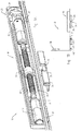
- Fig. 1A shows a part of a fitting arrangement 10 for windows, doors or the like with a frame and with a wing.
- the functioning of the fitting arrangement 10 in connection with a window is described below. It goes without saying, however, that the following explanations also apply in a corresponding manner to other areas of application of the fitting arrangement 10.
- the fitting arrangement 10 comprises sash-side and frame-side components, ie certain components of the fitting arrangement 10 are assigned to the sash of the window, while other components are assigned to the frame.
- a locking bar 12 is provided on the wing side and is arranged displaceably along its longitudinal axis. Depending on the position or functional position of the locking bar 12, the sash of the window can assume different positions, namely a locked position, a tilted position or a position which enables the sash to be opened by rotation.
- the locking bar 12 is covered at least in sections by a faceplate 14 with respect to the exterior of the wing, not shown.
- an actuating mechanism 16 is arranged, which comprises two coaxially arranged motors 18.
- the motors 18 can be operated electrically and, when energized, drive a threaded spindle 20 for a rotary movement, which is converted by means of a spindle nut 22 arranged in a rotationally fixed manner into a linear movement of a driver pin 24 which is fixedly connected to the spindle nut 22 or is formed in one piece.
- the driver pin 24 protrudes through an elongated hole 26 in the locking bar 12.
- the driver pin 24 also passes through Fig. 1A Elongated hole of the faceplate 14 not visible, so that the driver pin 24 projects into the outer space of the window sash, on which the locking bar 12 and the actuating mechanism 16 are arranged.
- the in Fig Fig. 1A Components shown in a - in the use position - lower edge of the window sash, more precisely in a lower, horizontal part of the window sash, arranged.
- Power is supplied via leaf-side and frame-side electrical contacts (not shown) which are in conductive connection when the window sash is arranged in a closed position or in a tilted position relative to the frame receiving the sash.
- leaf-side and frame-side electrical contacts (not shown) which are in conductive connection when the window sash is arranged in a closed position or in a tilted position relative to the frame receiving the sash.
- the electrical contacts are separated from one another, so that in this state the motors 18 are reliably prevented from being actuated unintentionally.
- the spatial arrangement of the actuation mechanism 16 in the lower part of the window sash thus enables the power supply for the motors 18 to be designed in a simple and at the same time secure manner.
- a position determination system 28 which has a potentiometer coupled to a gearwheel 30.
- the gearwheel 30 engages in corresponding recesses 32 in the locking bar 12, so that the gearwheel 30 is set in rotation when the locking bar 12 is moved.
- the potentiometer finally determines the position / position of the locking bar 12 from the measured rotational movement of the gear 30 in a manner known per se.
- Fig. 1A shows in addition to the wing-side components described above, a blocking rail 34 with a release recess 36.
- the function of the components 34, 36 is explained in more detail below.
- Figure 1B shows schematically the essential components of the fitting arrangement 10 in the same state as in FIG Fig. 1A .
- the sash of the window is locked in the frame in this state, the driver pin 24 is in a so-called zero position ("to zero position").
- the fitting arrangement 10 has, in addition to the electrically operable actuating mechanism 16, a handle 38 through which the locking bar 12 can also be moved. That is, the locking bar 12 can be moved both by the motors 18 and by the handle 38 in order, for example, to be able to bring the window into a tilted state starting from the closed position shown.
- Figure 1B further shows that the locking bar 12 has a first locking pin 40 and a second locking pin 40 '.
- the locking pin 40 is attached to the frame of the window in the area Bolt receptacle 42 arranged so that opening the wing is not possible.
- the driver pin 24 is on the other hand - as well Fig. 1A it can be seen - in the area of the release recess 36 of the blocking rail 34.
- the wing should be able to be opened even if the power supply to the motors 18 fails.
- the rotary opening position should not be able to be reached via the motors 18, but only manually via the handle 38.
- the fitting arrangement 10 must be designed in such a way that the locking bar 12 can also be displaced without the cooperation of the actuating mechanism 16.
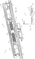
- the fitting arrangement 10 can do this because, as in the 2A and 2B shown, the locking bar 12 is rotatable by turning the handle 38 to the right when moving from the in 1A and 1B shown situation. Since the driver pin 24 in Fig. 1A is arranged at the right end of the elongated hole 26, the locking bar 12 can be moved to the right without the driver pin 24 preventing this movement.
- the driver pin 24 does not move relative to the release recess 36.
- the locking pins 40, 40 ' which are firmly attached to it are also moved to the right, as is the case Figure 2B can be seen.
- the pin 40 is then no longer blocked by the bolt receptacle 42.
- the pin 40 ' also does not stand in the way of opening the wing, since it has not yet been inserted into the bolt receptacle 42.
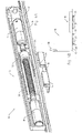
- the threaded spindle 20 is driven by the motors 18 to a rotary movement, which is converted via the spindle nut 22 into a linear movement of the driver pin 24 to the right. Since the driver pin 24 rests in the “zero position” at the right end of the elongated hole 26, the locking bar 12 is also moved to the right by the movement of the driver pin 24 until the tilting position of the locking bar 12 is reached.
- the locking pin 40 'prevents uncontrolled opening of the window sash in this position.
- the blocking rail 34 in cooperation with the part of the driver pin 24 protruding from the wing, ensures that even when the Figure 2B shown position of the pin 40, 40 'prevents unintentional opening of the window. In this situation, the pins 40, 40 'do not cooperate with the bolt receptacle 42, which is why they cannot have a securing effect. This take over the driver pin 24 and the blocking rail 34.
- the wing is at a transition from that in the Figure 1B position shown to in Figure 4B shown position reliably secured due to the driver pin 24 and the blocking rail 34. An automatic or remote-controlled transition of the window sash from a locked position into a tilted position - and vice versa - is therefore possible without risk.
- the fitting arrangement 10 must be actuated again starting from the "tilt-zero position".
- the motors 18 are activated, as a result of which the driving pin 24 is moved to the left and in the process takes the locking bar 12 with it until it reaches the 5A and 5B shown position is reached. Inadvertent opening of the wing - analogous to the situation described above - is reliably prevented when the locking bar 12 is displaced by the area of the blocking rail 34 arranged on the left of the release recess 36 in cooperation with the driving pin 24.
- the driver pin 24 is automatically moved back into the neutral position, in which the nut 22 is located approximately in the middle of the threaded spindle 20.
- the in the 1A and 1B The situation shown is then reached again and the fitting arrangement 10 is in the “zero position”, which makes it possible to move the locking bar 12 either manually - ie by means of the handle 38 - into the rotary opening position or into the tilting position or through the motors 18 to move to the tilt position.
Description
Die vorliegende Erfindung betrifft eine Beschlaganordnung für Fenster, Türen oder dergleichen mit einem Rahmen und mit einem Flügel, wobei die Beschlaganordnung flügelseitig eine Riegelstange, eine mechanische - insbesondere manuell bedienbare - Betätigungseinrichtung und zumindest einen Betätigungsmotor umfasst.The present invention relates to a fitting arrangement for windows, doors or the like with a frame and with a wing, the fitting arrangement comprising on the wing side a locking bar, a mechanical - in particular manually operated - actuating device and at least one actuating motor.
Die Beschlaganordnung ist wahlweise durch den Betätigungsmotor und die Betätigungseinrichtung betreibbar, d.h. die Riegelstange ist verschiebbar und sowohl durch den Betätigungsmotor als auch durch die Betätigungseinrichtung in eine erste sowie in eine zweite Funktionsstellung bringbar. Derartige motorbetriebene Beschlaganordnungen erhöhen den Bedienkomfort und ermöglichen beispielsweise auch eine ferngesteuerte Betätigung, um z.B. den Flügel in dem Rahmen von einer geschlossenen Stellung in eine gekippte Stellung - und umgekehrt - zu bringen.The fitting arrangement can optionally be operated by the actuating motor and the actuating device, i.e. the locking bar is displaceable and can be brought into a first and a second functional position both by the actuating motor and by the actuating device. Such motor-driven fitting arrangements increase ease of use and, for example, also enable remote-controlled actuation, e.g. to bring the wing in the frame from a closed position to a tilted position - and vice versa.
Nachteilig ist bei derartigen Beschlaganordnungen allerdings deren in der Regel komplexe und fehleranfällige Bauweise.A disadvantage of such fitting arrangements is their generally complex and error-prone construction.
Es ist daher eine Aufgabe der vorliegenden Erfindung, eine Beschlaganordnung der vorstehend genannten Art zu schaffen, die einfach aufgebaut und gleichzeitig zuverlässig betreibbar ist.It is therefore an object of the present invention to provide a fitting arrangement of the aforementioned type which is simple in construction and at the same time can be operated reliably.
Die
Diese Aufgabe wird durch eine Beschlaganordnung gemäß dem unabhängigen Anspruch 1 gelöst. Erfindungsgemäß sind der Betätigungsmotor und Komponenten zur antriebswirksamen Kopplung des Betätigungsmotors mit der Riegelstange zur Anordnung in einem Bereich eines - in Gebrauchslage - unteren Rands des Flügels ausgebildet. Erfindungsgemäß sind der Betätigungsmotor und die genannten Komponenten zur Anordnung in einem Bereich eines unteren Rands eines Flügelrahmens, beispielsweise in einem Fensterrahmen, ausgebildet.This object is achieved by a fitting arrangement according to independent claim 1. According to the invention, the actuating motor and components for drivingly coupling the actuating motor to the locking bar are designed to be arranged in a region of a lower edge of the wing, in the position of use. According to the invention, the actuating motor and the components mentioned are designed to be arranged in a region of a lower edge of a casement, for example in a window frame.
Diese Bauweise geht mit dem Vorteil einher, dass die für eine Betätigung der Beschlaganordnung durch den Betätigungsmotor erforderliche Energie auf einfache Weise zuführbar ist, da auch in einem gekippten Zustand des Flügels keine aufwendige Verkabelung zur Stromzufuhr erforderlich ist. Der untere Rand des Flügels steht nämlich auch in diesem Zustand in einem engen räumlichen Kontakt mit dem dem Flügel zugeordneten Rahmen, so dass entsprechende elektrische Kontakte vergleichsweise einfach ausgebildet sein können.This design is accompanied by the advantage that the energy required for actuating the fitting arrangement by the actuating motor can be supplied in a simple manner, since no complex wiring for power supply is required even when the sash is tilted. In this state, too, the lower edge of the wing is in close spatial contact with the frame assigned to the wing, so that corresponding electrical contacts can be designed to be comparatively simple.
Es kann vorgesehen sein, dass der Betätigungsmotor über ein Mitnehmerelement mit der Riegelstange antriebswirksam koppelbar ist, wobei die Riegelstange einen Antriebszapfen aufweist, der in einem antriebswirksam gekoppelten Zustand mit einer von zwei einander zugewandten Antriebsflächen des durch den Betätigungsmotor verfahrbaren Mitnehmerelements zusammenwirkt. Beispielsweise ist das Mitnehmerelement bei dieser Ausführungsform - bildlich gesprochen - als flaches U-Profil ausgebildet, wobei die Innenseiten der Schenkel des U-Profils die Antriebsflächen bilden. Durch eine seitliche Verschiebung des U-Profils kann entweder die eine oder die andere Innenseite des U-Profils in Kontakt mit dem Antriebszapfen gebracht werden, um diesen - und damit auch die Riegelstange - ebenfalls verschieben zu können. Der die Schenkel verbindende Abschnitt des U-Profils definiert den Weg, den das Mitnehmerelement zurücklegen muss, um von einer Kopplung mit einer der Antriebsflächen zu einer Kopplung mit der anderen Antriebsfläche zu gelangen. Der die Schenkel verbindende Abschnitt definiert somit eine Art "Leerlauf zwischen zwei antriebswirksam gekoppelten Zuständen, bei denen ein Verfahren des Mitnehmerelements über die entsprechende Antriebsfläche auf den Antriebszapfen und damit letztlich auf die Riegelstange übertragen wird. Es versteht sich, dass auch eine kinematische Umkehr des vorstehend beschriebenen Konstruktionsprinzips vorstellbar ist. In diesem Fall ist dem Betätigungsmotor ein zapfenartiges Mitnehmerelement zugeordnet, während die Riegelstange zwei Antriebsflächen, beispielsweise zwei Ansätze, ein U-förmiges Kopplungselement, eine Ausnehmung und/oder eine Öffnung umfasst, zwischen die bzw. in die das zapfenartige Mitnehmerelement eingreift.It can be provided that the actuating motor can be coupled to the locking rod in a drive-effective manner via a driver element, the locking rod having a drive pin which, in a drive-effectively coupled state, interacts with one of two mutually facing drive surfaces of the driver element which can be moved by the actuating motor. For example, the driver element in this embodiment - figuratively speaking - is designed as a flat U-profile, the inner sides of the legs of the U-profile forming the drive surfaces. By moving the U-profile laterally, either one or the other inside of the U-profile can come into contact with the drive pin brought in order to be able to move it - and thus also the locking bar. The section of the U-profile connecting the legs defines the path that the driver element has to travel in order to move from a coupling with one of the drive surfaces to a coupling with the other drive surface. The section connecting the legs thus defines a kind of "idling between two drive-coupled states, in which a movement of the driver element is transmitted via the corresponding drive surface to the drive pin and thus ultimately to the locking bar. It goes without saying that a kinematic reversal of the above In this case, the actuating motor is assigned a pin-like driver element, while the locking bar comprises two drive surfaces, for example two lugs, a U-shaped coupling element, a recess and / or an opening between and into which the pin-like driver element intervenes.
Gemäß einer Ausführungsform ist ein mit dem Betätigungsmotor antriebswirksam gekoppeltes, insbesondere zapfenartig ausgebildetes Mitnehmerelement vorgesehen, das selektiv mit der Riegelstange in antriebswirksame Kopplung bringbar ist und das die Riegelstange durchgreift, so dass das Mitnehmerelement aus dem Flügel hervorragt. Das Mitnehmerelement kann dadurch nicht nur zum Antrieb der Riegelstange vorgesehen sein, sondern zusätzlich weitere Funktionen erfüllen, die für einen zuverlässigen Betrieb der Beschlaganordnung dienlich sind.According to one embodiment, a driver element, which is coupled to the actuating motor in a drive-effective manner, in particular in the form of a pin, is provided, which can be selectively brought into a drive-effective coupling with the locking bar and which engages through the locking bar so that the driver element protrudes from the wing. As a result, the driver element can not only be provided for driving the locking bar, but can also perform additional functions which are useful for reliable operation of the fitting arrangement.
Insbesondere ist das Mitnehmerelement linear verfahrbar.In particular, the driver element can be moved linearly.
Dem Betätigungsmotor kann eine Steuereinheit zugeordnet sein, die derart ausgestaltet ist, dass das Mitnehmerelement in eine erste Stellung, in eine zweite Stellung und in eine Neutralstellung bringbar ist, wobei die Neutralstellung insbesondere zwischen der ersten und der zweiten Stellung liegt. Gemäß einer konstruktiv einfachen Bauweise ist die Steuereinheit so ausgebildet, dass lediglich die vorstehend genannten diskreten Stellungen eingenommen werden können und die Einnahme von weiteren Zwischenstellungen nicht vorgesehen ist. Ferner kann die Steuereinheit derart ausgestaltet sein, dass das Mitnehmerelement nach Erreichen der ersten und der zweiten Stellung automatisch in die Neutralstellung verfahrbar ist, so dass das Mitnehmerelement nach einem Verfahren in die erste oder die zweite Stellung stets wieder in eine wohldefinierte Grundoder Neutralstellung gebracht wird.A control unit can be assigned to the actuating motor, which is designed such that the driver element is in a first position, in a second position and can be brought into a neutral position, the neutral position being in particular between the first and the second position. According to a structurally simple construction, the control unit is designed in such a way that only the above-mentioned discrete positions can be taken and the taking of further intermediate positions is not provided. Furthermore, the control unit can be designed in such a way that the driver element can automatically be moved into the neutral position after reaching the first and the second position, so that the driver element is always brought back into a well-defined basic or neutral position by a method in the first or the second position.
Das Mitnehmerelement kann derart mit der Riegelstange koppelbar sein, dass ein Verfahren des Mitnehmerelements in die erste Stellung ein Verschieben der Riegelstange in die erste Funktionsstellung bewirkt und dass ein Verfahren des Mitnehmerelements in die zweite Stellung ein Verschieben der Riegelstange in die zweite Funktionsstellung bewirkt. Insbesondere ist die Riegelstange in eine dritte Funktionsstellung bringbar, die zwischen der ersten und der zweiten Funktionsstellung liegt. Dabei ist es insbesondere von Vorteil, wenn die Riegelstange und das Mitnehmerelement derart ausgestaltet sind, dass die Riegelstange durch eine Betätigung der Betätigungseinrichtung ohne Mitwirkung des Mitnehmerelements in die dritte Funktionsstellung bringbar ist. Mit anderen Worten soll die Riegelstange auch und insbesondere nur ohne die Mitwirkung des Betätigungsmotors in die dritte Funktionsstellung bringbar sein.The driver element can be coupled to the locking bar in such a way that moving the driver element into the first position causes the locking bar to be moved into the first functional position and that moving the driving element into the second position causes the locking bar to be moved into the second functional position. In particular, the locking bar can be brought into a third functional position, which lies between the first and the second functional position. It is particularly advantageous if the locking bar and the driver element are configured such that the locking bar can be brought into the third functional position by actuating the actuating device without the driver element participating. In other words, the locking bar should also and in particular only be able to be brought into the third functional position without the cooperation of the actuating motor.
Die erste Funktionsstellung der Riegelstange definiert eine Verriegelungsstellung der Beschlaganordnung, in der der Flügel in dem Rahmen verriegelt ist. Die zweite Funktionsstellung definiert eine Kippstellung der Beschlaganordnung, in der der Flügel in dem Rahmen verkippbar ist. Die dritte Funktionsstellung kann eine Drehstellung der Beschlaganordnung definieren, in der der Flügel in dem Rahmen durch eine Drehung bewegbar ist, d.h. in üblicher Weise drehgeöffnet werden kann.The first functional position of the locking bar defines a locking position of the fitting arrangement, in which the sash is locked in the frame. The second functional position defines a tilt position of the Fitting arrangement in which the sash can be tilted in the frame. The third functional position can define a rotational position of the fitting arrangement, in which the sash can be moved in the frame by rotation, ie can be opened in the usual way.
Ein Durchgreifen des Mitnehmerelements durch die Riegelstange kann auf einfache Weise erreicht werden, wenn diese ein Langloch aufweist, durch das das Mitnehmerelement ragt. Die Länge des Langlochs in Längsrichtung der Riegelstange kann - unter Berücksichtigung der Ausdehnung des Mitnehmerelements in dieser Richtung - der Strecke entsprechen, die erforderlich ist, um die Riegelstange von der ersten Funktionsstellung in die zweite Funktionsstellung zu verschieben. Wenn das Mitnehmerelement nach dem Verfahren in eine der beiden Stellungen wieder in die Neutralstellung verfahren wird, bewirkt die vorstehend beschriebene Ausgestaltung, dass das Mitnehmerelement in der Neutralstellung wieder im Bereich eines der Enden des Langlochs angeordnet ist oder sogar an dem Ende anschlägt. Soll ausgehend von dieser Situation eine andere Funktionsstellung eingenommen werden, so werden eine Betätigung des Betätigungsmotors und eine entsprechende Bewegung des Mitnehmerelements gleich in eine Bewegung der Riegelstange umgesetzt.Reaching through the locking element by the locking bar can be achieved in a simple manner if it has an elongated hole through which the driving element protrudes. The length of the elongated hole in the longitudinal direction of the locking bar can - taking into account the expansion of the driver element in this direction - correspond to the distance required to move the locking bar from the first functional position into the second functional position. If the driver element is moved back into the neutral position after the method in one of the two positions, the configuration described above causes the driver element in the neutral position to be arranged again in the region of one of the ends of the elongated hole or even to strike the end. If a different functional position is to be assumed based on this situation, an actuation of the actuating motor and a corresponding movement of the driver element are immediately converted into a movement of the locking bar.
Gemäß einer konstruktiv einfachen Ausführungsform der Beschlaganordnung ist der Betätigungsmotor antriebswirksam mit einer Gewindespindel gekoppelt, wobei die Gewindespindel insbesondere über eine Spindelmutter mit dem Mitnehmerelement in antriebswirksamer Verbindung steht. Die Gewindespindel ist insbesondere mindestens doppelt so lang wie das Langloch der Riegelstange.According to a structurally simple embodiment of the fitting arrangement, the actuating motor is coupled to a threaded spindle in a drive-effective manner, the threaded spindle being in a drive-effective connection with the driver element, in particular via a spindle nut. The threaded spindle is in particular at least twice as long as the elongated hole of the locking bar.
Um die erforderliche Antriebsleistung bei gleichzeitig kompakter Bauweise der Beschlaganordnung bereitstellen zu können, können zwei Betätigungsmotoren vorgesehen sein, die insbesondere koaxial angeordnet sind. Beispielsweise ist eine Gewindespindel vorgesehen, die an beiden Enden - bevorzugt über ein Getriebe oder auch direkt - von jeweils einem Betätigungsmotor angetrieben wird.In order to be able to provide the required drive power with a compact design of the fitting arrangement, two actuating motors can be used be provided, which are arranged in particular coaxially. For example, a threaded spindle is provided which is driven at both ends - preferably via a gear or also directly - by an actuating motor in each case.
Zum Schutz der Funktionskomponenten der Beschlaganordnung kann die Riegelstange zwischen dem Betätigungsmotor und einer Stulpschiene angeordnet sein, die die Riegelstange gegenüber dem Außenraum des Flügels zumindest abschnittsweise abdeckt und durch die das Mitnehmerelement ragt.To protect the functional components of the fitting arrangement, the locking bar can be arranged between the actuating motor and a faceplate, which at least in sections covers the locking bar with respect to the outer space of the wing and through which the driver element projects.
Zur Erhöhung der Betriebssicherheit kann die Beschlaganordnung eine Positionsbestimmungseinrichtung zur Bestimmung der Position der Riegelstange aufweisen. Die Positionsbestimmungseinrichtung umfasst insbesondere einen Drehwinkelsensor - beispielsweise ein Potentiometer -, der über ein in Ausnehmungen der Riegelstange eingreifendes Zahnrad mit der Riegelstange gekoppelt ist.To increase operational safety, the fitting arrangement can have a position determining device for determining the position of the locking bar. The position determining device comprises in particular a rotation angle sensor - for example a potentiometer - which is coupled to the locking rod via a gearwheel engaging in recesses in the locking rod.
Um den Flügel in dem Rahmen während des Verschiebens der Riegelstange von der ersten in die zweite Funktionsstellung zu sichern, kann die Beschlaganordnung rahmenseitig einen Blockademechanismus umfassen. Der Blockademechanismus gewährleistet, dass der Flügel relativ zu dem Rahmen während des Verschiebens der Riegelstange von der ersten in die zweite Funktionsstellung - und umgekehrt - keine unbeabsichtigten Bewegungen ausführen kann.In order to secure the sash in the frame during the displacement of the locking bar from the first to the second functional position, the fitting arrangement can comprise a blocking mechanism on the frame side. The blocking mechanism ensures that the wing cannot make any unintentional movements relative to the frame during the displacement of the locking bar from the first to the second functional position - and vice versa.
Der Blockademechanismus kann eine Freigabeeinrichtung aufweisen, die derart ausgestaltet ist, dass der Blockademechanismus in einer Neutralstellung des Mitnehmerelements nicht mit diesem zusammenwirkt. Insbesondere wenn das Mitnehmerelement nach einem Verfahren in die erste oder in die zweite Stellung automatisch wieder in die Neutralstellung gebracht wird, ermöglicht es die Freigabeeinrichtung, dass ein Drehöffnen des Flügels ohne eine motorische Betätigung des Mitnehmerelements möglich ist und durch die Komponenten des motorischen Betätigungssystems auch nicht verhindert wird. Beispielsweise kann die Riegelstange durch die Betätigungseinrichtung in die dritte Funktionsstellung gebracht werden, um beispielsweise den Flügel öffnen zu können, ohne dass die vorstehend beschriebene Sicherungswirkung des Blockademechanismus dem entgegensteht. Dies kann insbesondere in Notfällen relevant sein, in denen die Öffnung des Flügels erforderlich ist, ohne dass auf eine Betätigung des Betätigungsmotors zurückgegriffen werden kann (etwa bei einem Stromausfall) oder soll.The blocking mechanism can have a release device which is designed in such a way that the blocking mechanism does not interact with the driver element in a neutral position. In particular if the driver element in the first by a method or is automatically brought back into the neutral position in the second position, the release device makes it possible for the wing to be opened for rotation without motorized actuation of the driver element and also not prevented by the components of the motorized actuation system. For example, the locking bar can be brought into the third functional position by the actuating device in order, for example, to be able to open the sash without the locking action of the blocking mechanism described above being contrary to this. This can be particularly relevant in emergencies, in which the opening of the wing is required without the actuation motor being able to be used (for example in the event of a power failure).
Insbesondere ist der Blockademechanismus ein rahmenseitiges Bauteil, beispielsweise eine an dem Rahmen befestigbare Schiene, mit der das Mitnehmerelement während des Verschiebens zusammenwirkt. Die Freigabeeinrichtung kann bei dieser Bauweise z.B. eine Ausnehmung in der Schiene sein, durch die das Mitnehmerelement in der Neutralstellung geführt werden kann.In particular, the blocking mechanism is a frame-side component, for example a rail which can be fastened to the frame and with which the driver element interacts during the displacement. With this design, the release device can e.g. be a recess in the rail through which the driver element can be guided in the neutral position.
Alternativ ist es möglich, dass der Blockademechanismus einen Elektromagneten umfasst, der eine flügelseitige und eine rahmenseitige Komponente aufweist. Um die Sicherung des Flügels bei einem Verschieben der Riegelstange zwischen der ersten und der zweiten Funktionsstellung zu bewirken, wird der Elektromagnet bestromt.Alternatively, it is possible for the blocking mechanism to comprise an electromagnet which has a wing-side and a frame-side component. In order to secure the wing when the locking bar is moved between the first and the second functional position, the electromagnet is energized.
Gemäß einer Ausführungsform der Beschlaganordnung ist die Riegelstange mit zumindest einem Riegelzapfen versehen, der in der ersten und/oder in der zweiten Funktionsstellung der Riegelstange mit einer Riegeleinrichtung zusammenwirkt, die ein rahmenseitiger Bestandteil der Beschlaganordnung ist. Insbesondere ist die Riegelstange mit einem ersten Riegelzapfen und mit einem zweiten Riegelzapfen versehen, die voneinander beabstandet sind, wobei der erste Riegelzapfen in der ersten Funktionsstellung der Riegelstange mit der Riegeleinrichtung zusammenwirkt und wobei der zweite Riegelzapfen in der zweiten Funktionsstellung der Riegelstange mit der Riegeleinrichtung zusammenwirkt. Die Riegeleinrichtung kann eine Riegelschiene oder -aufnahme sein, deren Längserstreckung kürzer ist als der Abstand zwischen dem ersten und dem zweiten Riegelzapfen.According to one embodiment of the fitting arrangement, the locking bar is provided with at least one locking pin which, in the first and / or in the second functional position of the locking bar, interacts with a locking device which is part of the frame of the fitting arrangement is. In particular, the locking bar is provided with a first locking pin and with a second locking pin which are spaced apart from one another, the first locking pin interacting with the locking device in the first functional position of the locking bar and the second locking pin interacting with the locking device in the second functional position of the locking bar. The locking device can be a locking rail or holder, the longitudinal extent of which is shorter than the distance between the first and the second locking pin.
Um den Flügel in dem Rahmen - insbesondere automatisch und/oder ferngesteuert - auf komfortable und zuverlässige Weise in eine Kippstellung und wieder zurück bringen zu können, ist eine Kippeinrichtung vorgesehen. Die Kippeinrichtung ist erfindungsgemäß durch eine mechanische Zwangsführung direkt oder indirekt mit dem Betätigungsmotor und/oder der Betätigungseinrichtung antriebswirksam gekoppelt. Insbesondere ist die Riegelstange eine Komponente dieser Kopplung. Die mechanische Zwangsführung bewirkt, dass eine Betätigung des Betätigungsmotors oder der Betätigungseinrichtung nicht nur zu einer Bewegung der Riegelstange führt, sondern dass auch aktiv eine Kippbewegung des Flügels erzeugt wird. Die Ausgestaltung der Zwangsführung stellt durch mechanische zusammenwirkende Komponenten sicher, dass lediglich die gewünschte Bewegung - d.h. ein Verkippen des Flügels aus einer Schließstellung in eine Kippstellung und zurück - durchgeführt werden kann.In order to be able to move the sash into the tilting position and back again in a comfortable and reliable manner, in particular automatically and / or remotely, a tilting device is provided. According to the invention, the tilting device is directly or indirectly coupled to the actuating motor and / or the actuating device by means of a mechanical positive guidance. In particular, the locking bar is a component of this coupling. The mechanical positive guidance means that an actuation of the actuating motor or the actuating device not only leads to a movement of the locking bar, but also that an active tilting movement of the wing is generated. The design of the positive guidance ensures through mechanical interacting components that only the desired movement - i.e. the wing can be tilted from a closed position into a tilted position and back.
Die Erfindung betrifft ferner ein Fenster, eine Türe oder dergleichen mit einem Rahmen, mit einem Flügel und mit einer Beschlaganordnung gemäß zumindest einer der vorstehend beschriebenen Ausführungsformen.The invention further relates to a window, a door or the like with a frame, with a wing and with a fitting arrangement according to at least one of the embodiments described above.
Weitere Ausführungsformen der Erfindung sind in den Ansprüchen, der Beschreibung und den beigefügten Zeichnungen angegeben.Further embodiments of the invention are specified in the claims, the description and the accompanying drawings.
Nachfolgend wird die vorliegende Erfindung rein beispielhaft anhand einer vorteilhaften Ausführungsform unter Bezugnahme auf die beigefügten Zeichnungen erläutert. Es zeigen:
- Fig. 1A, 2A, 3A, 4A und 5A
- perspektivische Ansichten eines Teils der erfindungsge-mäßen Beschlaganordnung in verschiedenen Betätigungszuständen und
- Fig. 1B, 2B, 3B, 4B und 5B
- die Beschlaganordnung schematisch in den entsprechenden Betätigungszuständen.
- Figures 1A, 2A, 3A, 4A and 5A
- perspective views of a part of the fitting arrangement according to the invention in different operating states and
- Figures 1B, 2B, 3B, 4B and 5B
- the fitting arrangement schematically in the corresponding actuation states.
Die Beschlaganordnung 10 umfasst flügelseitige und rahmenseitige Komponenten, d.h. bestimmte Komponenten der Beschlaganordnung 10 sind dem Flügel des Fensters zugeordnet, während andere Komponenten dem Rahmen zugeordnet sind. Flügelseitig ist eine Riegelstange 12 vorgesehen, die entlang ihrer Längsachse verschiebbar angeordnet ist. Je nachdem, in welcher Lage oder Funktionsstellung sich die Riegelstange 12 befindet, kann der Flügel des Fensters unterschiedliche Stellungen einnehmen, nämlich eine verriegelte Stellung, eine Kippstellung oder eine Stellung, die das Öffnen des Fensterflügels durch eine Drehung ermöglicht.The
Die Riegelstange 12 wird gegenüber dem Außenraum des nicht gezeigten Flügels zumindest abschnittsweise durch eine Stulpschiene 14 abgedeckt. Auf der der Stulpschiene 14 abgewandten Seite der Riegelstange 12 ist ein Betätigungsmechanismus 16 angeordnet, der zwei koaxial angeordnete Motoren 18 umfasst. Die Motoren 18 sind elektrisch betreibbar und treiben bei Bestromung eine Gewindespindel 20 zu einer Drehbewegung an, die mittels einer drehfest angeordneten Spindelmutter 22 in eine lineare Bewegung eines mit der Spindelmutter 22 fest verbundenen oder einstückig ausgebildeten Mitnehmerzapfens 24 umgesetzt wird. Der Mitnehmerzapfen 24 ragt durch ein Langloch 26 in der Riegelstange 12. Der Mitnehmerzapfen 24 durchtritt auch ein in
Um eine Stromzufuhr für die Motoren 18 zu vereinfachen, sind die in
Um stets erfassen zu können, in welcher Lage sich die Riegelstange 12 befindet, ist ein Positionsbestimmungssystem 28 vorgesehen, das ein mit einem Zahnrad 30 gekoppeltes Potentiometer aufweist. Das Zahnrad 30 greift in entsprechende Ausnehmungen 32 der Riegelstange 12 ein, so dass das Zahnrad 30 bei einer Bewegung der Riegelstange 12 in eine Drehbewegung versetzt wird. Das Potentiometer bestimmt aus der gemessenen Drehbewegung des Zahnrads 30 schließlich in an sich bekannter Weise die Position/Stellung der Riegelstange 12.In order to always be able to detect the position of the locking
Prinzipiell soll der Flügel auch bei einem Ausfall der Stromversorgung der Motoren 18 geöffnet werden können. Insbesondere soll die Drehöffnungsstellung aus Sicherheitsgründen nicht über die Motoren 18, sondern nur manuell über den Griff 38 erreicht werden können. D.h. die Beschlaganordnung 10 muss derart ausgestaltet sein, dass die Riegelstange 12 auch ohne Mitwirkung des Betätigungsmechanismus 16 verschoben werden kann. Die Beschlaganordnung 10 vermag dies zu leisten, da, wie in den
Aus der
Alternativ zu der vorstehend beschriebenen manuellen Betätigung der Beschlaganordnung 10 kann diese auch durch die Motoren 18 betätigt werden. Ausgehend von der in den
Wie in
Um allerdings sicherzustellen, dass der Flügel auch in einem Notfall manuell aus der Kippstellung in die Drehöffnungsstellung gebracht werden kann, wird nach Erreichen der in den
Wenn das Fenster wieder geschlossen werden soll, muss die Beschlaganordnung 10 ausgehend von der "Kipp-Nulllage" erneut betätigt werden. Zu diesem Zweck werden die Motoren 18 aktiviert, wodurch der Mitnehmerzapfen 24 nach links verfahren wird und dabei die Riegelstange 12 mitnimmt, bis die in den
Nachdem die Riegelstange 12 in die geschlossene Funktionsstellung verfahren wurde, wird der Mitnehmerzapfen 24 wieder automatisch in die Neutrallage verfahren, bei der sich die Mutter 22 in etwa in der Mitte der Gewindespindel 20 befindet. Die in den
- 1010th
- BeschlaganordnungFitting arrangement
- 1212th
- RiegelstangeLocking bar
- 1414
- StulpschieneFaceplate
- 1616
- BetätigungsmechanismusOperating mechanism
- 1818th
- Motorengine
- 2020th
- GewindespindelThreaded spindle
- 2222
- SpindelmutterSpindle nut
- 2424th
- MitnehmerzapfenDriver pin
- 2626
- LanglochLong hole
- 2828
- PositionsbestimmungseinrichtungPositioning device
- 3030th
- Zahnradgear
- 3232
- AusnehmungRecess
- 3434
- BlockierschieneBlocking rail
- 3636
- FreigabeausnehmungRelease recess
- 3838
- GriffHandle
- 40, 40'40, 40 '
- RiegelzapfenDeadbolt
- 4242
- RiegelaufnahmeTransom mount
Claims (13)
- A fitting arrangement for windows, doors or the like having a frame and having a leaf,wherein the fitting arrangement comprises at the leaf side a locking bar (12), a mechanical manually operable actuation device (38) and at least one actuation motor (18),wherein the locking bar (12) is displaceable and can be brought into a first functional position and into a second functional position by both the actuation motor (18) and the actuation device (38), andwherein the actuation motor (18) and components (20, 22, 24) for the drive-effective coupling of the actuation motor (18) to the locking bar (12) are configured for an arrangement in a region of a - in the position of use - lower margin of the leaf in a leaf frame,characterized in that
a tilting device is provided by which the leaf can be brought into a tilt position in the frame, with the tilting device being directly or indirectly drive-effectively coupled to the actuation motor (18) and/or to the actuation device (38) by a mechanical compulsory guidance such that an actuation of the actuation motor (18) or of the actuation device (38) not only results in a movement of the locking bar (12), but such that a tilting movement of the leaf is also actively produced. - A fitting arrangement in accordance with claim 1,
characterized in that
the actuation motor (18) is drive-effectively couplable to the locking bar via an entrainment element, in particular a linearly travelable entrainment element, with the locking bar having a drive spigot which cooperates with one of two mutually facing drive surfaces of the entrainment element in a drive-effectively coupled state. - A fitting arrangement for windows, doors or the like having a frame and having a leaf in accordance with claim 1,
wherein an entrainment element (24) which is in particular spigot-like and/or linearly travelable is provided which is drive-effectively coupled to the actuation motor (18), which can selectively be brought into a drive-effective coupling with the locking bar (12) and which engages through the locking bar (12) such that the entrainment element (24) projects out of the leaf in an assembled state of the fitting arrangement. - A fitting arrangement in accordance with at least one of the preceding claims,
characterized in that
a control unit is associated with the actuation motor (18) and is configured such that the entrainment element (24) can be brought into a first position, into a second position and into a neutral position, with the neutral position in particular lying between the first position and the second position, and with the control unit in particular being configured such that the entrainment element (24) can automatically be traveled into the neutral position after reaching the first position or the second position. - A fitting arrangement in accordance with at least one of the preceding claims,
characterized in that
the entrainment element (24) is couplable to the locking bar (12) such that a traveling of the entrainment element (24) into the first position effects a displacement of the locking bar (12) into the first functional position and such that a traveling of the entrainment element (24) into the second position effects a displacement of the locking bar (12) into the second functional position. - A fitting arrangement in accordance with at least one of the preceding claims,
characterized in that
the locking bar (12) can be brought into a third functional position which lies between the first functional position and the second functional position, with the locking bar (12) and the entrainment element (24) in particular being configured such that the locking bar (12) can be brought into the third functional position by an actuation of the actuation device (38) without participation of the entrainment element (24). - A fitting arrangement in accordance with at least one of the claims 2 to 6,
characterized in that
the locking bar (12) has an elongate hole (26) through which the entrainment element (24) projects, with the length of the elongate hole (26) in the longitudinal direction of the locking bar (12) - while taking into account the extent of the entrainment element (24) in this direction - in particular corresponding to the distance which is required to displace the locking bar (12) from the first functional position into the second functional position. - A fitting arrangement in accordance with at least one of the preceding claims,
characterized in that
the actuation motor (18) is drive-effectively coupled to a threaded spindle (20), with the threaded spindle (20) in particular being in drive-effective connection with the entrainment element (24) via a spindle nut (22); and/or in that two actuation motors (18) are provided which are in particular coaxially arranged. - A fitting arrangement in accordance with at least one of the preceding claims,
characterized in that
the locking bar (12) is arranged between the actuation motor (18) and a cover rail (14) which at least sectionally covers the locking bar (12) with respect to the outer space of the leaf and which projects through the entrainment element (24). - A fitting arrangement in accordance with at least one of the preceding claims,
characterized in that
the fitting arrangement has a position determination device (28) for determining the position of the locking bar (12), with the position determination device (28) in particular comprising an angle of rotation sensor, in particular a potentiometer, which is coupled to the locking bar (12) via a toothed wheel (30) which engages into recesses (32) of the locking bar (12). - A fitting arrangement in accordance with at least one of the preceding claims,
characterized in that
the fitting arrangement comprises at the frame side a blockage mechanism (24, 34) by which the leaf can be secured during the displacement of the locking bar (12) from the first functional position into the second functional position, with the blockage mechanism (24, 34) in particular having a release device (36) which is configured such that the blockage mechanism (24, 34) does not cooperate with the entrainment element (24) in a neutral position thereof, and/or with the blockage mechanism (24, 34) comprising a rail (34) with which the entrainment element (24) cooperates during the displacement. - A fitting arrangement in accordance with at least one of the preceding claims,
characterized in that
the locking bar (12) is provided with at least one locking pin (40, 40') which cooperates with a frame-side locking device (42) of the fitting arrangement in the first functional position and/or in the second functional position of the locking bar (12), with the locking bar (12) in particular being provided with a first locking pin (40) and with a second locking pin (40') which are spaced apart from one another, with the first locking pin (40) cooperating with the locking device (42) in the first functional position of the locking bar (12) and with the second locking pin (40') cooperating with the locking device (42) in the second functional position of the locking bar (12), with the locking device preferably being a latch receiver (42) whose longitudinal extent is shorter than the spacing between the first and second locking pins (40, 40'). - A window, a door or the like having a frame, having a leaf and having a fitting arrangement in accordance with at least one of the claims 1 to 12.
Priority Applications (1)
| Application Number | Priority Date | Filing Date | Title |
|---|---|---|---|
| PL18179199T PL3401475T3 (en) | 2012-02-13 | 2013-02-07 | Fitting device |
Applications Claiming Priority (2)
| Application Number | Priority Date | Filing Date | Title |
|---|---|---|---|
| DE202012001475U DE202012001475U1 (en) | 2012-02-13 | 2012-02-13 | fitting assembly |
| EP13154435.5A EP2626491B1 (en) | 2012-02-13 | 2013-02-07 | Fitting device |
Related Parent Applications (2)
| Application Number | Title | Priority Date | Filing Date |
|---|---|---|---|
| EP13154435.5A Division EP2626491B1 (en) | 2012-02-13 | 2013-02-07 | Fitting device |
| EP13154435.5A Division-Into EP2626491B1 (en) | 2012-02-13 | 2013-02-07 | Fitting device |
Publications (2)
| Publication Number | Publication Date |
|---|---|
| EP3401475A1 EP3401475A1 (en) | 2018-11-14 |
| EP3401475B1 true EP3401475B1 (en) | 2020-04-29 |
Family
ID=47722051
Family Applications (2)
| Application Number | Title | Priority Date | Filing Date |
|---|---|---|---|
| EP18179199.7A Active EP3401475B1 (en) | 2012-02-13 | 2013-02-07 | Fitting device |
| EP13154435.5A Active EP2626491B1 (en) | 2012-02-13 | 2013-02-07 | Fitting device |
Family Applications After (1)
| Application Number | Title | Priority Date | Filing Date |
|---|---|---|---|
| EP13154435.5A Active EP2626491B1 (en) | 2012-02-13 | 2013-02-07 | Fitting device |
Country Status (3)
| Country | Link |
|---|---|
| EP (2) | EP3401475B1 (en) |
| DE (1) | DE202012001475U1 (en) |
| PL (2) | PL3401475T3 (en) |
Families Citing this family (6)
| Publication number | Priority date | Publication date | Assignee | Title |
|---|---|---|---|---|
| DE102012214003A1 (en) * | 2012-08-07 | 2014-02-13 | Brose Fahrzeugteile Gmbh & Co. Kg, Coburg | Closing device for a building opening |
| FR3005326B1 (en) | 2013-05-02 | 2015-06-05 | Hydro Building Systems | MOTORIZED DEVICE FOR LOCKING / UNLOCKING AN OPENER, IN PARTICULAR A WINDOW |
| DE202017107392U1 (en) | 2016-12-08 | 2018-03-09 | Maco Technologie Gmbh | Sliding element |
| DE202019100744U1 (en) | 2019-02-08 | 2020-05-11 | Aumüller Aumatic GmbH | Tilt drive device for a wing |
| DE102019105034A1 (en) * | 2019-02-27 | 2020-08-27 | Gröninger Antriebstechnik GmbH & Co. KG | Door or window arrangement with a drive unit in the frame |
| US11905751B2 (en) * | 2022-04-21 | 2024-02-20 | ABT Systems, LLC | Housing for mounting and adjusting the alignment of a window actuator |
Family Cites Families (11)
| Publication number | Priority date | Publication date | Assignee | Title |
|---|---|---|---|---|
| DE3812675C2 (en) * | 1988-04-18 | 1997-06-19 | Horst Grimm Fa | Door for a transport vehicle |
| DE19603770A1 (en) * | 1996-02-02 | 1997-08-07 | Winkhaus Fa August | Window, door or the like with a fitting system |
| ATE298033T1 (en) * | 2001-03-20 | 2005-07-15 | Schueco Int Kg | DRIVE UNIT FOR WINDOWS OR DOORS |
| DE10139675A1 (en) * | 2001-08-11 | 2003-02-20 | Winkhaus Fa August | locking device |
| DE20204224U1 (en) | 2002-03-16 | 2002-05-23 | Winkhaus Fa August | Device for issuing and locking a wing pivotally arranged on a frame |
| EP1405974B1 (en) * | 2002-10-01 | 2008-01-09 | Somfy S.A.S. | Locking mechanism for turn and tilt window or door |
| ATE312991T1 (en) * | 2003-02-19 | 2005-12-15 | Roto Frank Ag | WINDOW, DOOR OR THE LIKE HAVING A MOTOR DRIVE UNIT FOR A DRIVE ROD ARRANGEMENT |
| DE10308243B4 (en) * | 2003-02-25 | 2006-11-02 | Carl Fuhr Gmbh & Co. Kg | Locking system, in particular door lock, window lock or the like |
| DE10346883A1 (en) * | 2003-10-09 | 2005-05-04 | Winkhaus Fa August | Electric driver for window or door espagnolette, has drive unit connectable to shaft extending through driver casing to connect handle to drive pinion on espagnolette |
| DE102004015147A1 (en) | 2004-03-27 | 2005-10-13 | Aug. Winkhaus Gmbh & Co. Kg | driving means |
| KR101023954B1 (en) * | 2006-10-23 | 2011-03-28 | (주)엘지하우시스 | Lift and Slide apparatus by motor for window |
-
2012
- 2012-02-13 DE DE202012001475U patent/DE202012001475U1/en not_active Expired - Lifetime
-
2013
- 2013-02-07 EP EP18179199.7A patent/EP3401475B1/en active Active
- 2013-02-07 PL PL18179199T patent/PL3401475T3/en unknown
- 2013-02-07 PL PL13154435T patent/PL2626491T3/en unknown
- 2013-02-07 EP EP13154435.5A patent/EP2626491B1/en active Active
Non-Patent Citations (1)
| Title |
|---|
| None * |
Also Published As
| Publication number | Publication date |
|---|---|
| PL2626491T3 (en) | 2019-05-31 |
| EP2626491A2 (en) | 2013-08-14 |
| PL3401475T3 (en) | 2020-11-30 |
| EP3401475A1 (en) | 2018-11-14 |
| EP2626491B1 (en) | 2018-09-12 |
| EP2626491A3 (en) | 2016-12-21 |
| DE202012001475U1 (en) | 2013-05-15 |
Similar Documents
| Publication | Publication Date | Title |
|---|---|---|
| EP3401475B1 (en) | Fitting device | |
| EP3612696B1 (en) | Vehicle door handle arrangement | |
| EP2320016A1 (en) | Vertical control device for a lifting sliding door | |
| EP2206862A2 (en) | Tongue drive for locking or unlocking a sliding leaf | |
| DE4321099A1 (en) | Ventilation device for windows or doors - involves drive rod system for locking and unlocking casement frame to and from blind frame. | |
| EP2146032A1 (en) | Device for opening and/or shutting and locking a closed state of a shutting device for shutting a spatial opening and shutting device with such a device | |
| EP2520746B1 (en) | Electrically actuated lock | |
| EP2169156B1 (en) | Mortise lock without deadbolt | |
| EP1865130A1 (en) | Unbolting assembly of a window, door or similar | |
| EP3045624A1 (en) | Locking device for a pivoting mounted wing | |
| WO2023143823A1 (en) | Shifting device for the forced shifting of a leaf, in particular a sliding leaf, of a window or a door | |
| DE10308243B4 (en) | Locking system, in particular door lock, window lock or the like | |
| DE19900875C2 (en) | Locking device for a door system | |
| EP1255905A1 (en) | Operating device | |
| EP3662123B1 (en) | Motor lock | |
| DE10257688A1 (en) | Closing device for an opening provided in a vehicle with a single slide guide rail and corresponding vehicle | |
| DE10038867B4 (en) | Door system with locking device | |
| EP1344883B1 (en) | Locking device for a door | |
| EP1990492A2 (en) | Motor lock with multiple point locking | |
| EP1790805B1 (en) | Drive with a lever gear for an espagnolette | |
| EP1816291A2 (en) | Drive device for a boltable window leaf in a frame | |
| DE3221110A1 (en) | FITTING FOR A TILTING AND FOLLOWING AT LEAST PARALLEL CANCELED WING OF A WINDOW, DOOR OR. DGL. | |
| EP2453086B1 (en) | Connecting rod for the fixed leaf of double-leafed windows or doors without mullion | |
| EP3702555B1 (en) | Door or window arrangement with a drive unit in the window frame | |
| EP0668426A1 (en) | Fitting for windows or doors |
Legal Events
| Date | Code | Title | Description |
|---|---|---|---|
| PUAI | Public reference made under article 153(3) epc to a published international application that has entered the european phase |
Free format text: ORIGINAL CODE: 0009012 |
|
| STAA | Information on the status of an ep patent application or granted ep patent |
Free format text: STATUS: THE APPLICATION HAS BEEN PUBLISHED |
|
| AC | Divisional application: reference to earlier application |
Ref document number: 2626491 Country of ref document: EP Kind code of ref document: P |
|
| AK | Designated contracting states |
Kind code of ref document: A1 Designated state(s): AL AT BE BG CH CY CZ DE DK EE ES FI FR GB GR HR HU IE IS IT LI LT LU LV MC MK MT NL NO PL PT RO RS SE SI SK SM TR |
|
| STAA | Information on the status of an ep patent application or granted ep patent |
Free format text: STATUS: REQUEST FOR EXAMINATION WAS MADE |
|
| 17P | Request for examination filed |
Effective date: 20190424 |
|
| RBV | Designated contracting states (corrected) |
Designated state(s): AL AT BE BG CH CY CZ DE DK EE ES FI FR GB GR HR HU IE IS IT LI LT LU LV MC MK MT NL NO PL PT RO RS SE SI SK SM TR |
|
| RIC1 | Information provided on ipc code assigned before grant |
Ipc: E05C 9/08 20060101AFI20190913BHEP Ipc: E05B 47/02 20060101ALI20190913BHEP Ipc: E05D 15/52 20060101ALI20190913BHEP Ipc: E05C 9/00 20060101ALI20190913BHEP Ipc: E05B 47/00 20060101ALI20190913BHEP |
|
| GRAP | Despatch of communication of intention to grant a patent |
Free format text: ORIGINAL CODE: EPIDOSNIGR1 |
|
| STAA | Information on the status of an ep patent application or granted ep patent |
Free format text: STATUS: GRANT OF PATENT IS INTENDED |
|
| INTG | Intention to grant announced |
Effective date: 20191115 |
|
| GRAS | Grant fee paid |
Free format text: ORIGINAL CODE: EPIDOSNIGR3 |
|
| GRAA | (expected) grant |
Free format text: ORIGINAL CODE: 0009210 |
|
| STAA | Information on the status of an ep patent application or granted ep patent |
Free format text: STATUS: THE PATENT HAS BEEN GRANTED |
|
| AC | Divisional application: reference to earlier application |
Ref document number: 2626491 Country of ref document: EP Kind code of ref document: P |
|
| AK | Designated contracting states |
Kind code of ref document: B1 Designated state(s): AL AT BE BG CH CY CZ DE DK EE ES FI FR GB GR HR HU IE IS IT LI LT LU LV MC MK MT NL NO PL PT RO RS SE SI SK SM TR |
|
| REG | Reference to a national code |
Ref country code: GB Ref legal event code: FG4D Free format text: NOT ENGLISH |
|
| REG | Reference to a national code |
Ref country code: CH Ref legal event code: EP |
|
| REG | Reference to a national code |
Ref country code: AT Ref legal event code: REF Ref document number: 1263536 Country of ref document: AT Kind code of ref document: T Effective date: 20200515 |
|
| REG | Reference to a national code |
Ref country code: DE Ref legal event code: R096 Ref document number: 502013014672 Country of ref document: DE |
|
| REG | Reference to a national code |
Ref country code: IE Ref legal event code: FG4D Free format text: LANGUAGE OF EP DOCUMENT: GERMAN |
|
| REG | Reference to a national code |
Ref country code: NL Ref legal event code: MP Effective date: 20200429 |
|
| REG | Reference to a national code |
Ref country code: LT Ref legal event code: MG4D |
|
| PG25 | Lapsed in a contracting state [announced via postgrant information from national office to epo] |
Ref country code: LT Free format text: LAPSE BECAUSE OF FAILURE TO SUBMIT A TRANSLATION OF THE DESCRIPTION OR TO PAY THE FEE WITHIN THE PRESCRIBED TIME-LIMIT Effective date: 20200429 Ref country code: FI Free format text: LAPSE BECAUSE OF FAILURE TO SUBMIT A TRANSLATION OF THE DESCRIPTION OR TO PAY THE FEE WITHIN THE PRESCRIBED TIME-LIMIT Effective date: 20200429 Ref country code: NO Free format text: LAPSE BECAUSE OF FAILURE TO SUBMIT A TRANSLATION OF THE DESCRIPTION OR TO PAY THE FEE WITHIN THE PRESCRIBED TIME-LIMIT Effective date: 20200729 Ref country code: SE Free format text: LAPSE BECAUSE OF FAILURE TO SUBMIT A TRANSLATION OF THE DESCRIPTION OR TO PAY THE FEE WITHIN THE PRESCRIBED TIME-LIMIT Effective date: 20200429 Ref country code: PT Free format text: LAPSE BECAUSE OF FAILURE TO SUBMIT A TRANSLATION OF THE DESCRIPTION OR TO PAY THE FEE WITHIN THE PRESCRIBED TIME-LIMIT Effective date: 20200831 Ref country code: IS Free format text: LAPSE BECAUSE OF FAILURE TO SUBMIT A TRANSLATION OF THE DESCRIPTION OR TO PAY THE FEE WITHIN THE PRESCRIBED TIME-LIMIT Effective date: 20200829 Ref country code: GR Free format text: LAPSE BECAUSE OF FAILURE TO SUBMIT A TRANSLATION OF THE DESCRIPTION OR TO PAY THE FEE WITHIN THE PRESCRIBED TIME-LIMIT Effective date: 20200730 |
|
| PG25 | Lapsed in a contracting state [announced via postgrant information from national office to epo] |
Ref country code: BG Free format text: LAPSE BECAUSE OF FAILURE TO SUBMIT A TRANSLATION OF THE DESCRIPTION OR TO PAY THE FEE WITHIN THE PRESCRIBED TIME-LIMIT Effective date: 20200729 Ref country code: RS Free format text: LAPSE BECAUSE OF FAILURE TO SUBMIT A TRANSLATION OF THE DESCRIPTION OR TO PAY THE FEE WITHIN THE PRESCRIBED TIME-LIMIT Effective date: 20200429 Ref country code: HR Free format text: LAPSE BECAUSE OF FAILURE TO SUBMIT A TRANSLATION OF THE DESCRIPTION OR TO PAY THE FEE WITHIN THE PRESCRIBED TIME-LIMIT Effective date: 20200429 Ref country code: LV Free format text: LAPSE BECAUSE OF FAILURE TO SUBMIT A TRANSLATION OF THE DESCRIPTION OR TO PAY THE FEE WITHIN THE PRESCRIBED TIME-LIMIT Effective date: 20200429 |
|
| PG25 | Lapsed in a contracting state [announced via postgrant information from national office to epo] |
Ref country code: AL Free format text: LAPSE BECAUSE OF FAILURE TO SUBMIT A TRANSLATION OF THE DESCRIPTION OR TO PAY THE FEE WITHIN THE PRESCRIBED TIME-LIMIT Effective date: 20200429 Ref country code: NL Free format text: LAPSE BECAUSE OF FAILURE TO SUBMIT A TRANSLATION OF THE DESCRIPTION OR TO PAY THE FEE WITHIN THE PRESCRIBED TIME-LIMIT Effective date: 20200429 |
|
| PG25 | Lapsed in a contracting state [announced via postgrant information from national office to epo] |
Ref country code: RO Free format text: LAPSE BECAUSE OF FAILURE TO SUBMIT A TRANSLATION OF THE DESCRIPTION OR TO PAY THE FEE WITHIN THE PRESCRIBED TIME-LIMIT Effective date: 20200429 Ref country code: CZ Free format text: LAPSE BECAUSE OF FAILURE TO SUBMIT A TRANSLATION OF THE DESCRIPTION OR TO PAY THE FEE WITHIN THE PRESCRIBED TIME-LIMIT Effective date: 20200429 Ref country code: ES Free format text: LAPSE BECAUSE OF FAILURE TO SUBMIT A TRANSLATION OF THE DESCRIPTION OR TO PAY THE FEE WITHIN THE PRESCRIBED TIME-LIMIT Effective date: 20200429 Ref country code: DK Free format text: LAPSE BECAUSE OF FAILURE TO SUBMIT A TRANSLATION OF THE DESCRIPTION OR TO PAY THE FEE WITHIN THE PRESCRIBED TIME-LIMIT Effective date: 20200429 Ref country code: SM Free format text: LAPSE BECAUSE OF FAILURE TO SUBMIT A TRANSLATION OF THE DESCRIPTION OR TO PAY THE FEE WITHIN THE PRESCRIBED TIME-LIMIT Effective date: 20200429 Ref country code: EE Free format text: LAPSE BECAUSE OF FAILURE TO SUBMIT A TRANSLATION OF THE DESCRIPTION OR TO PAY THE FEE WITHIN THE PRESCRIBED TIME-LIMIT Effective date: 20200429 |
|
| REG | Reference to a national code |
Ref country code: DE Ref legal event code: R097 Ref document number: 502013014672 Country of ref document: DE |
|
| PG25 | Lapsed in a contracting state [announced via postgrant information from national office to epo] |
Ref country code: SK Free format text: LAPSE BECAUSE OF FAILURE TO SUBMIT A TRANSLATION OF THE DESCRIPTION OR TO PAY THE FEE WITHIN THE PRESCRIBED TIME-LIMIT Effective date: 20200429 |
|
| PLBE | No opposition filed within time limit |
Free format text: ORIGINAL CODE: 0009261 |
|
| STAA | Information on the status of an ep patent application or granted ep patent |
Free format text: STATUS: NO OPPOSITION FILED WITHIN TIME LIMIT |
|
| 26N | No opposition filed |
Effective date: 20210201 |
|
| PG25 | Lapsed in a contracting state [announced via postgrant information from national office to epo] |
Ref country code: SI Free format text: LAPSE BECAUSE OF FAILURE TO SUBMIT A TRANSLATION OF THE DESCRIPTION OR TO PAY THE FEE WITHIN THE PRESCRIBED TIME-LIMIT Effective date: 20200429 |
|
| PG25 | Lapsed in a contracting state [announced via postgrant information from national office to epo] |
Ref country code: MC Free format text: LAPSE BECAUSE OF FAILURE TO SUBMIT A TRANSLATION OF THE DESCRIPTION OR TO PAY THE FEE WITHIN THE PRESCRIBED TIME-LIMIT Effective date: 20200429 |
|
| GBPC | Gb: european patent ceased through non-payment of renewal fee |
Effective date: 20210207 |
|
| REG | Reference to a national code |
Ref country code: BE Ref legal event code: MM Effective date: 20210228 |
|
| PG25 | Lapsed in a contracting state [announced via postgrant information from national office to epo] |
Ref country code: LU Free format text: LAPSE BECAUSE OF NON-PAYMENT OF DUE FEES Effective date: 20210207 Ref country code: LI Free format text: LAPSE BECAUSE OF NON-PAYMENT OF DUE FEES Effective date: 20210228 Ref country code: CH Free format text: LAPSE BECAUSE OF NON-PAYMENT OF DUE FEES Effective date: 20210228 |
|
| PG25 | Lapsed in a contracting state [announced via postgrant information from national office to epo] |
Ref country code: GB Free format text: LAPSE BECAUSE OF NON-PAYMENT OF DUE FEES Effective date: 20210207 Ref country code: FR Free format text: LAPSE BECAUSE OF NON-PAYMENT OF DUE FEES Effective date: 20210228 Ref country code: IE Free format text: LAPSE BECAUSE OF NON-PAYMENT OF DUE FEES Effective date: 20210207 |
|
| PG25 | Lapsed in a contracting state [announced via postgrant information from national office to epo] |
Ref country code: BE Free format text: LAPSE BECAUSE OF NON-PAYMENT OF DUE FEES Effective date: 20210228 |
|
| PGFP | Annual fee paid to national office [announced via postgrant information from national office to epo] |
Ref country code: AT Payment date: 20230217 Year of fee payment: 11 |
|
| PGFP | Annual fee paid to national office [announced via postgrant information from national office to epo] |
Ref country code: PL Payment date: 20230127 Year of fee payment: 11 Ref country code: IT Payment date: 20230223 Year of fee payment: 11 Ref country code: DE Payment date: 20230216 Year of fee payment: 11 |
|
| PG25 | Lapsed in a contracting state [announced via postgrant information from national office to epo] |
Ref country code: CY Free format text: LAPSE BECAUSE OF FAILURE TO SUBMIT A TRANSLATION OF THE DESCRIPTION OR TO PAY THE FEE WITHIN THE PRESCRIBED TIME-LIMIT Effective date: 20200429 |
|
| PG25 | Lapsed in a contracting state [announced via postgrant information from national office to epo] |
Ref country code: HU Free format text: LAPSE BECAUSE OF FAILURE TO SUBMIT A TRANSLATION OF THE DESCRIPTION OR TO PAY THE FEE WITHIN THE PRESCRIBED TIME-LIMIT; INVALID AB INITIO Effective date: 20130207 |