EP2520746B1 - Electrically actuated lock - Google Patents
Electrically actuated lock Download PDFInfo
- Publication number
- EP2520746B1 EP2520746B1 EP20110003731 EP11003731A EP2520746B1 EP 2520746 B1 EP2520746 B1 EP 2520746B1 EP 20110003731 EP20110003731 EP 20110003731 EP 11003731 A EP11003731 A EP 11003731A EP 2520746 B1 EP2520746 B1 EP 2520746B1
- Authority
- EP
- European Patent Office
- Prior art keywords
- lock
- actuation part
- lock according
- bolt
- movement
- Prior art date
- Legal status (The legal status is an assumption and is not a legal conclusion. Google has not performed a legal analysis and makes no representation as to the accuracy of the status listed.)
- Not-in-force
Links
Images


Classifications
-
- E—FIXED CONSTRUCTIONS
- E05—LOCKS; KEYS; WINDOW OR DOOR FITTINGS; SAFES
- E05B—LOCKS; ACCESSORIES THEREFOR; HANDCUFFS
- E05B47/00—Operating or controlling locks or other fastening devices by electric or magnetic means
- E05B47/02—Movement of the bolt by electromagnetic means; Adaptation of locks, latches, or parts thereof, for movement of the bolt by electromagnetic means
-
- E—FIXED CONSTRUCTIONS
- E05—LOCKS; KEYS; WINDOW OR DOOR FITTINGS; SAFES
- E05B—LOCKS; ACCESSORIES THEREFOR; HANDCUFFS
- E05B47/00—Operating or controlling locks or other fastening devices by electric or magnetic means
- E05B47/0001—Operating or controlling locks or other fastening devices by electric or magnetic means with electric actuators; Constructional features thereof
- E05B47/0012—Operating or controlling locks or other fastening devices by electric or magnetic means with electric actuators; Constructional features thereof with rotary electromotors
-
- E—FIXED CONSTRUCTIONS
- E05—LOCKS; KEYS; WINDOW OR DOOR FITTINGS; SAFES
- E05B—LOCKS; ACCESSORIES THEREFOR; HANDCUFFS
- E05B47/00—Operating or controlling locks or other fastening devices by electric or magnetic means
- E05B2047/0084—Key or electric means; Emergency release
- E05B2047/0086—Emergency release, e.g. key or electromagnet
- E05B2047/0087—Electric spare devices, e.g. auxiliary batteries or capacitors for back up
-
- E—FIXED CONSTRUCTIONS
- E05—LOCKS; KEYS; WINDOW OR DOOR FITTINGS; SAFES
- E05B—LOCKS; ACCESSORIES THEREFOR; HANDCUFFS
- E05B63/00—Locks or fastenings with special structural characteristics
- E05B63/08—Mortise locks
Definitions
- the present invention relates to an electrically actuable lock.
- Such locks are known in the art and can, for. B. in security areas are used.
- a two-step unlocking option is desirable.
- the pre-unlocking preferably by a person authorized for this purpose, the blocking position of the castle is canceled. Then, in a second stage, it is possible to completely pull back the latch of the lock so as to open the door.
- Such a lock is known for example from the EP 1 160 398 , According to the EP 1 160 398
- the emergency release consists of its pivotally mounted driver and a resiliently arranged on the driver, positively coupled to the actuating member driving element.
- Such a lock is particularly suitable for use in security areas.
- Part of the lock is in addition to the latch mounted in the lock housing actuating part, which is actuated by an electric drive via two defined ranges of motion.
- the electrically driven actuating part is coupled to a blocking element by means of a first coupling device, ie the movement of the actuating part leads to a defined movement of the blocking element.
- the blocking element is mounted in the lock housing and can be actuated in the manner mentioned from a blocking position to an unlocked position, wherein in the locked position, the lock is blocked against opening of the door.
- the electrically operable lock is designed so that in any position an emergency operation in the event of an electrical failure or power failure should be possible.
- a disadvantage of the known lock is that the electric drive comprises an electric motor which is connected via a reduction gear with the actuating part.
- the electric motor In order to enable a mechanical closing, in which yes the reduction gear, which is in frictional connection with the engine, would brake, the electric motor is pivotable about an axis of the reduction gear, so that the worm shaft, which otherwise engages positively in the gears of the reduction gear , is lifted off the gear.
- the present invention seeks to further develop a generic lock in that this is easier to assemble and assemble with fewer components and also allows improved control even after a mechanical actuation.
- the electric drive has a stepper motor. Stepper motors can be precisely controlled easily, so that a large measuring and Control effort and thus a complex assembly and wiring costs account.
- the drive according to the invention is provided with a linear drive.
- the stepper motor can advance the linear drive along a stretch and move back, wherein any position is detectable and identifiable.
- the linear drive is a spindle drive.
- a coupling element is arranged for engagement in the actuating part on the linear drive. The stepper motor thus moves the coupling element back and forth along a straight path by means of the linear drive. In this way, the operating part with which the coupling element is engaged can also be moved back and forth in a controlled manner.
- Stepper motor, linear drive and coupling element may be formed according to an advantageous proposal as an assembly.
- This assembly can be pivoted spring-loaded in its entirety, so that the coupling element is lifted out of engagement with the confirmation part. Since the stepping motor or the controller knows the position of the coupling element, the coupling element only has to be moved into the engaged position with respect to the moving part after the assembly has been pivoted back, in which case the control precisely detects and knows the position.
- the coupling element is spring-loaded from its engagement position designed to be displaceable or pivotable.
- buttons for detecting the end positions of the actuating part and / or the bolt are provided in the embodiment according to the invention.
- a control electronics may be formed directly in the lock, which may also have an interface for connection to an external control or central control.
- the emergency release for coupling with the actuating part is formed with a tumbler.
- the device for pivoting or displacement of the assembly or the coupling element for mechanical separation of the power flow from the electric drive to the operating part can be carried out according to a proposal of the invention.
- an electrically actuated lock is proposed which on can be easily manufactured and assembled, compared with prior art locks requires fewer components and provides improved control.
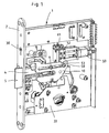
- a locking element 8 is also mounted in the lock housing.
- an operating part 10 is also mounted in the lock housing.
- the actuating member 10 perform a translational movement parallel to the direction of movement of the bolt 4.
- the operating part 10 in order to better show its shape and structure, drawn double hatched. It can be seen that the actuating part 10 is located in a plane above both the bolt 4, as well as the blocking element 8.
- the actuating member 10 is designed along one of its longitudinal edges as a rack 11 which meshes with the last gear 12a of a further gear wheels 12 having reduction gear.
- the transmission is in frictional connection with an electric motor 13, the worm shaft 14 meshes with the first gear 12 of the transmission.
- the electric motor 13 is located on a pivotable about a housing pivot axis 15 motor mount 16.
- the motor carrier 16 engages the worm shaft 14 of the electric motor form-fitting manner in the gears 12 of the reduction gear. If, however, the motor mount 16 is pivoted clockwise about the pivot axis 15, this leads to a separation of the power flow between the electric motor 13 and reduction gear and thus to a separation of the power flow between the electric motor and the actuating member 10th
- Driver 21 and driver surface 22 therefore form a second coupling device 17a, which, unlike the first coupling device 17 between the locking element 8 and the actuating part 10, exclusively over the second range of movement of the operating part 10 is active. Therefore, the bolt 4 is unlocked, whereas the bolt is retracted over the second range of movement of the operating part 10 over the first range of movement of the operating part 10.
- the drive for both ranges of motion via the electric motor 13, wherein the drive but is strictly separated for the two movement range.
- buttons 23 detects the blocking position of the locking element 8, button 24 whose unlocked position.
- Button 25 detects the latch 4 in its extended and thus locked position, whereas button 26 detects that end position in which the bolt is retracted to the maximum.
- a preferably commercially designed profile cylinder 27 is arranged in the upper part of the lock housing 1. Its cam 27a acts on another button 28. Securing the profile cylinder 27 via a screw 29 which abuts with its head 30 on the face plate 2, while the screw itself protrudes far into the lock housing 1 and there with a thread 27b of the profile cylinder 27 is screwed. Close to the end of the screw 29 is a housing-fixed retaining element 27d for the screw and, also firmly in the lock housing 1, another button 31, which detects the end of the screw 29. So if the screw 29 is screwed out of the thread 27b, this leads after only a few turns to a switching contact on the button 31, which thus leads to a signal output. In this way manipulation attempts are counteracted to remove the profile cylinder 27.
- Another button 32 detects whether the lock housing 1 is located within a corresponding cutout of the door.
- the lock is provided with a mechanical emergency release 33.
- This consists of a pivotably arranged in the lock housing 1 driver 34 and a resiliently disposed on spring 40 on the driver 34 driver element 35.
- the driver element 35 is provided with a catch pin 36 which can engage in a recess 37 of the operating part 10.
- the mechanical drive of the driver 34 via a key-operated tumbler 39, which is arranged in the lower part of the lock housing 1.
- the driver 34 can be pivoted about the pivot axis 38 until the driver element 35 under pressure of the spring 40 snaps with its catch pin 36 into the recess 37 of the actuating part 10.
- Upon further movement of the driver 34 then takes place a forced coupling of the movement of the actuating member 10 with the movement of the driver 34.
- Due to the resilient mounting of the driver 35 on the driver 34 ensures that the catch pin 36 in each case into the recess 37 of the operating part 10 can snap, regardless of the position in which the operating member 10 is currently located.
- a decoupling of the electric motor 13 is provided.
- the driver 34 is provided with an actuating surface which cooperates with a cam 41 of the motor carrier 16. If the driver 34 is pivoted in the manner already described by means of the tumbler 39, this also leads, via the cam 41, to a pivoting of the motor mount 16 about its pivot axis 15 and thus to a decoupling of the electric motor 13 from the gearbox 12, 12a and the actuating part 10 ,
- the actuation of the tumbler 39 is detected by a button 42.
- a microprocessor 43 To control the lock is preferably located in the upper region of the lock housing 1, a microprocessor 43.
- the microprocessor 43 is connected via an interface with a central control and monitoring unit.
- the central control unit can be uniform for an entire building or corridor, in which case further similar locks with their microprocessors are also connected to the central control unit.
- the microprocessor 43 is also provided with inputs for the signals of the previously described button 23, 24, 25, 26 for monitoring the end positions of the locking element and the bolt. Comparable inputs exist for the signals of the push-buttons 31, 32, 42, which are also already described. Furthermore, there may still be optional inputs to be occupied, e.g. As for occupant closure control and to control the expansion of the keyhole cover to immediately detect any manipulation of the lock and report to the central control unit in these areas.
- the motor 13 with the worm shaft 14 is pivotally pivoted away about the pivot point 15 from the gear 12.
- the worm shaft 14 separates from the rest of the transmission 12 and the operating member 10 is moved. If the engine is swung back again, it may happen that the worm shaft 14 does not engage with the gearbox 12 at first. So there is an offset at engine startup. Then it is not clear in which position the actuating part 10 is translational, which is why a large variety of buttons must be used in the manner described.
- Fig. 1 was initially omitted for reasons of clarity on various modules in the presentation. These assemblies are, for example, the security lock with the profile cylinder 27 for actual lock actuation and the power capacitors 48 according to Fig. 5 , the also not shown. For the rest, however, it can be assumed that the function of the lock according to Fig. 1 and its structure according to Fig. 5 correspond.
- a stepper motor 50 which drives a spindle 51.
- a carriage 52 with an actuating cam 53, wherein the carriage 52 is guided on a slide guide 54.
- the carriage guide 54 includes a mounting plate 55 having a passageway long hole 56 and a mounting slot 57.
- a pivoting cam 58 is formed.
- stepper motor 50 The difference with regard to the entire assembly is the stepper motor 50 and the arrangement of the buttons for determining the respective end positions.
- actuating member 10 has no rack, but only a groove 59 for receiving the cam 53 on the carriage 52nd
- the actuator In the in Fig. 1 shown position, the actuator is in the most pushed forward position.
- the bolt head is in the outermost position and the bolt in the locked position.
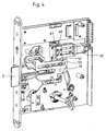
- Fig. 2 shows the other end position, wherein the stepping motor has moved via the spindle 51 in the most retracted position.
- the actuator 10 has been withdrawn.
- a first range of motion has initially been overcome in the usual way, in which the blocking element 8 has been raised in the guide 19, so that the path for the bolt has become free. Then with the actuator 10, the bolt was withdrawn.
- Fig. 1 shows the closed end position
- Fig. 2 the opened end position
- stepper motor assembly Due to the use of the stepper motor assembly now the number of buttons can be reduced and the technology for position determination can be considerably simplified.
- the embodiment of the invention allows that, in contrast to the prior art, only one button 61 is needed as a reference point for the stepper motor assembly or the stepper motor.
- the button 61 may be integrated in the stepper motor assembly, as shown in the FIGS. 1 . 2 and 4 is shown.
- an arrangement of the probe 61 at another location in the lock housing 1 is possible. It is only important that the stepper motor assembly designed so as to be displaceable in accordance with the invention can approach the pushbutton 61, that is to say the pushbutton 61 is arranged in the path of movement of the stepper motor assembly.
- the button 61 has a contact element which cooperates with the carriage 52 of the stepper motor assembly.
- the button 61 of the stepper motor assembly in a traversing movement with respect to the plane of the drawing after the FIGS. 1 . 2 and 4 contacted from left to right as well as from bottom to top. Since it is the stepper motor assembly according to the embodiment of the invention, which is designed to be movable, only one button 61 is required for the location detection. If the reference point formed by the button 61 is approached by the stepping motor 50, then all can other possible travel paths are controlled by means of the number of revolutions of the stepping motor 50.
- the button 61 is to be approached with the stepper motor assembly so as to detect or define a precise positioning, ie reference position. For this purpose, it may be necessary to reciprocate the stepper motor assembly several times, so that an unambiguous position determination can take place. This orientation is performed fully automatically microprocessor-based and requires only a moment.
Landscapes
- Physics & Mathematics (AREA)
- Electromagnetism (AREA)
- Lock And Its Accessories (AREA)
Description
Die vorliegende Erfindung betrifft ein elektrisch betätigbares Schloss.The present invention relates to an electrically actuable lock.
Derartige Schlösser sind im Stand der Technik bekannt und können z. B. in Sicherheitsbereichen zur Anwendung kommen. Bei solchen Schlössern ist eine zweistufige Entriegelungsmöglichkeit wünschenswert. In der Vorentriegelung wird, vorzugsweise durch eine hierfür autorisierte Person, die Blockierstellung des Schlosses aufgehoben. Sodann ist es in einer zweiten Stufe möglich, die Falle des Schlosses ganz zurückzuziehen, um so die Tür zu öffnen.Such locks are known in the art and can, for. B. in security areas are used. In such locks, a two-step unlocking option is desirable. In the pre-unlocking, preferably by a person authorized for this purpose, the blocking position of the castle is canceled. Then, in a second stage, it is possible to completely pull back the latch of the lock so as to open the door.
Sicherheitsschlösser mit diesen Eigenschaften sind vielfältig bekannt, so z. B. aus der
Ein gattungsgemäßes Schloss weist üblicherweise auf:
- a) einen mittels einer gehäusefesten Führung in einem Schlossgehäuse geführten Riegel,
- b) ein in dem Schlossgehäuse gelagertes, von einer Sperrstellung in eine Entsperrstellung betätigbares Sperrelement, welches das Schloss in der Sperrstellung gegen Öffnung blockiert,
- c) ein in dem Schlossgehäuse gelagertes Betätigungsteil, welches durch einen elektrischen Antrieb über zwei Bewegungsbereiche betätigbar ist,
- d) eine erste Kopplungseinrichtung, welche das Betätigungsteil in dessen erstem Bewegungsbereich mit dem Sperrelement koppelt,
- e) eine zweite Kopplungseinrichtung, welche das Betätigungsteil in dessen zweitem Bewegungsbereich mit dem Riegel koppelt und
- f) eine in dem Schlossgehäuse angeordnete, mit dem Betätigungsteil mechanisch in Eingriff bringbare Notentriegelung.
- a) guided by a housing-fixed guide in a lock housing latch
- b) a locking element which is mounted in the lock housing and which can be actuated from a blocking position into an unlocking position, blocking the lock in the blocking position against opening,
- c) an operating part which is mounted in the lock housing and which can be actuated by an electric drive over two movement ranges,
- d) a first coupling device which couples the actuating part in the first movement region with the blocking element,
- e) a second coupling device which couples the actuating part in the second movement range with the bolt and
- f) arranged in the lock housing, with the actuating part mechanically engageable emergency release.
Ein solches Schloss ist beispielsweise bekannt aus der
Ein derartiges Schloss eignet sich insbesondere für die Anwendung in Sicherheitsbereichen. Bestandteil des Schlosses ist neben dem Riegel ein in dem Schlossgehäuse gelagertes Betätigungsteil, welches durch einen elektrischen Antrieb über zwei definierte Bewegungsbereiche betätigbar ist. IN dem ersten Bewegungsbereich wird das elektrisch angetriebene Betätigungsteil mittels einer ersten Kopplungseinrichtung mit einem Sperrelement gekoppelt, d. h. die Bewegung des Betätigungsteils führt zu einer definierten Bewegung des Sperrelements. Das Sperrelement ist in dem Schlossgehäuse gelagert und lässt sich auf die genannte Weise von einer Sperrstellung in eine Entsperrstellung betätigen, wobei in der Sperrstellung das Schloss gegen ein Öffnen der Tür blockiert ist. Durch diese vorbekannten Ausgestaltung wird das elektrisch betätigbare Schloss so ausgebildet, dass in jeder Stellung ein Notbetrieb im Falle eines elektrischen Defektes oder bei Stromausfall möglich sein soll.Such a lock is particularly suitable for use in security areas. Part of the lock is in addition to the latch mounted in the lock housing actuating part, which is actuated by an electric drive via two defined ranges of motion. In the first movement range, the electrically driven actuating part is coupled to a blocking element by means of a first coupling device, ie the movement of the actuating part leads to a defined movement of the blocking element. The blocking element is mounted in the lock housing and can be actuated in the manner mentioned from a blocking position to an unlocked position, wherein in the locked position, the lock is blocked against opening of the door. By this known embodiment, the electrically operable lock is designed so that in any position an emergency operation in the event of an electrical failure or power failure should be possible.
Ein Nachteil des vorbekannten Schlosses besteht darin, dass der elektrische Antrieb einen Elektromotor umfasst, der über ein Untersetzungsgetriebe mit dem Betätigungsteil verbunden ist. Um ein mechanisches Schließen zu ermöglichen, bei welchem ja das Untersetzungsgetriebe, welches in kraftschlüssiger Verbindung mit dem Motor steht, bremsen würde, ist der Elektromotor um eine Achse vom Untersetzungsgetriebe wegschwenkbar ausgebildet, so dass die Schneckenwelle, welches ansonsten formschlüssig in die Zahnräder des Untersetzungsgetriebes eingreift, von dem Zahnrad abgehoben wird.A disadvantage of the known lock is that the electric drive comprises an electric motor which is connected via a reduction gear with the actuating part. In order to enable a mechanical closing, in which yes the reduction gear, which is in frictional connection with the engine, would brake, the electric motor is pivotable about an axis of the reduction gear, so that the worm shaft, which otherwise engages positively in the gears of the reduction gear , is lifted off the gear.
Hieraus ergibt sich grundsätzlich das Problem, dass bei einer Verschiebung des Betätigungsteils nach einem Abheben des Elektromotors vom Untersetzungsgetriebe keine eindeutige Position mehr identifizierbar ist. Aus diesem Grunde benötigt das vorbekannte Schloss eine große Vielzahl von Tastern und sonstigen Möglichkeiten zur Feststellung einer Position und wird insgesamt dadurch sehr aufwendig. Auch ist die Herstellung eines Untersetzungsgetriebes mit großem wirtschaftlichem Aufwand verbunden und stellt darüber hinaus eine zusätzliche mechanische Anfälligkeit bereit. Die verwendeten Elektromotoren sind ebenfalls sehr hochwertig und haben einen vergleichsweise hohen Energiebedarf.This results in principle in the problem that when a shift of the operating part after a lifting of the electric motor from the reduction gear no unique position is more identifiable. For this reason, the prior art lock requires a large variety of buttons and other options for detecting a position and is therefore very expensive as a whole. Also, the production of a reduction gear is associated with great economic effort and also provides an additional mechanical vulnerability. The electric motors used are also very high quality and have a relatively high energy consumption.
Aus dem Stand der Technik ist im Übrigen gemäß der
Ausgehend vom vorbeschriebenen Stand der Technik liegt der vorliegenden Erfindung die Aufgabe zugrunde, ein gattungsgemäßes Schloss dahingehend weiterzubilden, dass dieses mit weniger Bauteilen einfacherer aufbaubar und montierbar ist und darüber hinaus eine verbesserte Steuerung auch nach einer mechanischen Betätigung ermöglicht.Based on the above-described prior art, the present invention seeks to further develop a generic lock in that this is easier to assemble and assemble with fewer components and also allows improved control even after a mechanical actuation.
Zur technischen Lösung wird mit der Erfindung ein Schloss mit den Merkmalen des Anspruches 1 vorgeschlagen. Weitere Vorteile und Merkmale ergeben sich aus den Unteransprüchen.For technical solution is proposed with the invention, a lock with the features of
Erfindungsgemäß weist der elektrische Antrieb einen Schrittmotor auf. Schrittmotoren lassen sich ohne weiteres präzise ansteuern, so dass ein großer Mess- und Steuerungsaufwand und damit ein aufwendiger Montage- und Verdrahtungsaufwand entfallen.According to the invention, the electric drive has a stepper motor. Stepper motors can be precisely controlled easily, so that a large measuring and Control effort and thus a complex assembly and wiring costs account.
Darüber hinaus ist der Antrieb erfindungsgemäß mit einem Linearantrieb versehen. Der Schrittmotor kann den Linearantrieb entlang einer Strecke vor und zurück bewegen, wobei jegliche Position erfassbar und identifizierbar ist. In vorteilhafter Weise ist der Linearantrieb ein Spindelantrieb. Gemäß der Erfindung ist ein Kupplungselement für den Eingriff in das Betätigungsteil am Linearantrieb angeordnet. Der Schrittmotor bewegt somit das Kupplungselement mittels des Linearantriebes entlang einer geraden Strecke vor und zurück. Auf diese Weise kann das Betätigungsteil, mit welchem das Kupplungselement in Eingriff ist, ebenfalls gesteuert vor und zurück bewegt werden.In addition, the drive according to the invention is provided with a linear drive. The stepper motor can advance the linear drive along a stretch and move back, wherein any position is detectable and identifiable. Advantageously, the linear drive is a spindle drive. According to the invention, a coupling element is arranged for engagement in the actuating part on the linear drive. The stepper motor thus moves the coupling element back and forth along a straight path by means of the linear drive. In this way, the operating part with which the coupling element is engaged can also be moved back and forth in a controlled manner.
Schrittmotor, Linearantrieb und Kupplungselement können gemäß einem vorteilhaften Vorschlag als eine Baugruppe ausgebildet sein. Diese Baugruppe kann in ihrer Gesamtheit federbelastet verschwenkbar sein, so dass das Kupplungselement aus seinem Eingriff mit dem Bestätigungsteil herausgehoben wird. Da der Schrittmotor beziehungsweise die Steuerung die Position des Kupplungselementes kennt, muss nach einem Rückschwenken der Baugruppe das Kupplungselement nur noch in die Eingriffsposition in Bezug zum Bewegungsteil verfahren werden, wobei wiederum die Steuerung die Position exakt erfasst und kennt.Stepper motor, linear drive and coupling element may be formed according to an advantageous proposal as an assembly. This assembly can be pivoted spring-loaded in its entirety, so that the coupling element is lifted out of engagement with the confirmation part. Since the stepping motor or the controller knows the position of the coupling element, the coupling element only has to be moved into the engaged position with respect to the moving part after the assembly has been pivoted back, in which case the control precisely detects and knows the position.
Gemäß einem alternativen oder ergänzenden vorteilhaften Vorschlag der Erfindung ist das Kupplungselement federbelastet aus seiner Eingriffsposition verschiebbar oder verschwenkbar ausgebildet.According to an alternative or additional advantageous proposal of the invention, the coupling element is spring-loaded from its engagement position designed to be displaceable or pivotable.
In vorteilhafter Weise sind bei der erfindungsgemäßen Ausgestaltung nur noch Taster zur Erfassung der Endstellungen des Betätigungsteiles und/oder des Riegels vorgesehen.Advantageously, only buttons for detecting the end positions of the actuating part and / or the bolt are provided in the embodiment according to the invention.
Vorteilhafterweise kann eine Steuerelektronik direkt im Schloss ausgebildet sein, welches zudem eine Schnittstelle zur Verbindung mit einer außerhalb liegenden Steuerung oder Zentralsteuerung aufweisen kann.Advantageously, a control electronics may be formed directly in the lock, which may also have an interface for connection to an external control or central control.
In vorteilhafter Weise ist die Notentriegelung zur Kopplung mit dem Betätigungsteil mit einem Zuhaltungswerk ausgebildet. Mittels der Notentriegelung kann gemäß einem Vorschlag der Erfindung die Vorrichtung zur Verschwenkung oder Verschiebung der Baugruppe oder des Kupplungselementes zur mechanischen Trennung des Kraftflusses vom elektrischen Antrieb zum Betätigungsteil erfolgen.Advantageously, the emergency release for coupling with the actuating part is formed with a tumbler. By means of the emergency release, the device for pivoting or displacement of the assembly or the coupling element for mechanical separation of the power flow from the electric drive to the operating part can be carried out according to a proposal of the invention.
Mit der Erfindung wird ein elektrisch betätigbares Schloss vorgeschlagen, welches auf einfache Weise gefertigt und montiert werden kann, gegenüber vorbekannten Schlössern weniger Bauteile benötigt und eine verbesserte Ansteuerung bereitstellt.With the invention, an electrically actuated lock is proposed which on can be easily manufactured and assembled, compared with prior art locks requires fewer components and provides improved control.
Weitere Vorteile und Merkmale der Erfindung ergeben sich aus der folgenden Beschreibung anhand der Figuren. Dabei zeigen:
- Fig. 1
- eine perspektivische Darstellung eines elektrisch betätigbaren Schlosses gemäß einem Ausführungsbeispiel der Erfindung;
- Fig. 2
- eine Darstellung gemäß
Fig. 1 in einer anderen Position; - Fig.3
- eine perspektivische Darstellung für ein Ausführungsbeispiel einer Antriebsbaugruppe;
- Fig. 4
- eine perspektivische Darstellung des Schlosses gemäß
Fig. 1 in einer Notentriegelungsposition und - Fig. 5
- eine Schnittdarstellung eines elektrisch betätigbaren Sicherheitsschlosses gemäß dem Stand der Technik.
- Fig. 1
- a perspective view of an electrically actuated lock according to an embodiment of the invention;
- Fig. 2
- a representation according to
Fig. 1 in another position; - Figure 3
- a perspective view of an embodiment of a drive assembly;
- Fig. 4
- a perspective view of the castle according to
Fig. 1 in an emergency release position and - Fig. 5
- a sectional view of an electrically actuated security lock according to the prior art.
Aufbau und Funktion eines gattungsgemäßen Schlosses wird zunächst anhand der
- Das elektrisch betätigbare Schloss befindet sich in einem kastenförmigen Schlossgehäuse 1 und ist mittels eines Stulpes 2 an einer Tür befestigbar. In
dem Schlossgehäuse 1 ist auf gehäusefesten Führungszapfen 3ein Riegel 4 horizontal gelagert. In üblicher Weiseragt ein Riegelkopf 5 des Riegels ausdem Stulp 2 des Schlossgehäuses heraus, sofern sich derRiegel 4 in seiner Schließstellung befindet. Andem Verriegelungsabschnitt 5ist eine Fallenschräge 6 ausgebildet, da, wie nachfolgend noch näher beschrieben wird, derRiegel 4 bei dem beschriebenen Ausführungsbeispiel zugleich die Funktion einer Falle ausübt und er sich daher auch als "Riegelfalle" bezeichnen lässt.
- The electrically actuated lock is located in a box-shaped
lock housing 1 and can be fastened by means of aStulpes 2 to a door. In thelock housing 1, abolt 4 is mounted horizontally onguide pin 3 fixed to the housing. In the usual way, abolt head 5 of the bolt projects out of theforend 2 of the lock housing, provided that thebolt 4 is in its closed position. At the lockingportion 5, a trailingedge 6 is formed, since, as will be described in more detail below, thebolt 4 in the described embodiment at the same time performs the function of a case and it can therefore also be referred to as a "latch bolt".
Über weitere, gehäusefeste Führungszapfen 7 ist in dem Schlossgehäuse ferner ein Sperrelement 8 gelagert. Bei dem Ausführungsbeispiel kann das Sperrelement 8, geführt durch die Führungszapfen 7, eine Bewegung quer zu der Bewegung des Riegels 4 ausführen.About further, fixed to the housing guide pin 7 a
Über weitere gehäusefeste Führungszapfen 9 ist in dem Schlossgehäuse ferner ein Betätigungsteil 10 gelagert. Beim Ausführungsbeispiel kann das Betätigungsteil 10 eine translatorische Bewegung parallel zur Bewegungsrichtung des Riegels 4 ausführen. Auf der Zeichnung ist das Betätigungsteil 10, um dessen Form und Struktur besser hervortreten zu lassen, doppelt schraffiert eingezeichnet. Man erkennt, dass sich das Betätigungsteil 10 in einer Ebene oberhalb sowohl des Riegels 4, als auch des Sperrelementes 8 befindet. Das Betätigungsteil 10 ist entlang eines seiner Längsränder als Zahnstange 11 gestaltet, die mit dem letzten Zahnrad 12a eines weitere Zahnräder 12 aufweisenden Untersetzungsgetriebes kämmt. Das Getriebe steht im Kraftschluss mit einem Elektromotor 13, dessen Schneckenwelle 14 mit dem ersten Zahnrad 12 des Getriebes kämmt.Further housing-fixed
Der Elektromotor 13 befindet sich auf einem um eine gehäusefeste Schwenkachse 15 schwenkbaren Motorträger 16. In der in
Elektromotor 13, Riegel 4, Sperrelement 8 und Betätigungsteil 10 wirken wie folgt zusammen:
- Aus der in
Figur 5Schlossgehäuse herausgefahrenem Riegel 4 lässt sich derRiegel 4 zurückziehen, indem über entsprechende Ansteuerungssignale der Elektromotor 13 betätigt wird. Über das ausden Zahlrädern Zahnstange 11 desBetätigungsteils 10, wodurch sich dieses in der Zeichnungsebene nach rechts bewegt. Über eine erste Kopplungseinrichtung 17 führt der erste Teil der Bewegung des Betätigungsteils 10 zu einer analogen Bewegung desSperrelementes 8. Hierzu ist andem Sperrelement 8ein Zapfen 18 angebracht, der ineine Führung 19 desBetätigungsteils 10 eingreift.Die Führung 19 ist als Zwangsführung in Gestalt eines einmal schräg abgeknickten Langloches ausgeführt, dessen erster Bereich schräg sowohl zur Bewegungsrichtung des Betätigungsteils 10, als auch schräg zur Bewegungsrichtung des Sperrelementes 8 verläuft. Die Bewegung des Betätigungsteils 10 führt daher infolge des schrägen Abschnittes der Führung 19 zu einer auf der Zeichnung nach oben gerichteten Bewegung desSperrelementes 8.Das Sperrelement 8 wird von seiner Sperrstellung in seine Entsperrstellung überführt. Letztere ist dadurch gekennzeichnet, dassein Blockierelement 20 desSperrelementes 8, welches zunächst in den Bewegungsbereich desRiegels 4 ragt und diesen daher blockiert, mit dem Sperrelement zurückgezogen wird und damit den Bewegungsbereich desRiegels 4 freigibt.
- From the in
FIG. 5 shown closed position with fully moved out of thelock housing latch 4, thelatch 4 can pull back by theelectric motor 13 is actuated via appropriate control signals. About the consisting of thenumber wheels rack 11 of theactuating part 10, whereby this moves in the drawing plane to the right. Via a first coupling device 17, the first part of the movement of theactuating part 10 leads to an analogous movement of the blockingelement 8. For this purpose, apin 18 is attached to the blockingelement 8, which engages in aguide 19 of theactuating part 10. Theguide 19 is a forced guidance in the form of a once obliquely bent oblong hole executed, the first region obliquely both to the direction of movement of theactuating part 10, as well as obliquely to the direction of movement of thelocking element 8 extends. Therefore, the movement of the operatingpart 10 results in an upward movement of the blockingelement 8 as a result of the oblique section of theguide 19. The blockingelement 8 is transferred from its blocking position into its unlocked position. The latter is characterized in that a blockingelement 20 of thelocking element 8, which initially projects into the range of movement of thebolt 4 and therefore blocks it, is withdrawn with the blocking element and thus releases the range of movement of thebolt 4.
Über die Länge des voranstehend geschilderten ersten Bewegungsbereichs des Betätigungsteils 10 verharrt der Riegel 4 in seiner in
Zur Erfassung der Endstellungen des Sperrelements 8 und des Riegels 4 sind insgesamt vier Kontakte bzw. Taster vorgesehen. Taster 23 erfasst die Sperrstellung des Sperrelements 8, Taster 24 dessen Entsperrstellung. Taster 25 erfasst den Riegel 4 in dessen ausgefahrener und damit verriegelter Stellung, wohingegen Taster 26 jene Endstellung erfasst, in der der Riegel maximal zurückgezogen ist.To detect the end positions of the
Im oberen Teil des Schlossgehäuses 1 ist ein vorzugsweise handelsüblich gestalteter Profilzylinder 27 angeordnet. Dessen Nocken 27a wirkt auf einen weiteren Taster 28. Die Sicherung des Profilzylinders 27 erfolgt über eine Schraube 29, die mit ihrem Kopf 30 an dem Stulp 2 anliegt, während die Schraube selbst weit in das Schlossgehäuse 1 hineinragt und dort mit einem Gewinde 27b des Profilzylinders 27 verschraubt ist. Nahe am Ende der Schraube 29 befindet sich ein gehäusefestes Halteelement 27d für die Schraube sowie, ebenfalls fest in dem Schlossgehäuse 1, ein weiterer Taster 31, welcher das Ende der Schraube 29 detektiert. Wird also die Schraube 29 aus dem Gewinde 27b herausgedreht, führt dies bereits nach wenigen Umdrehungen zu einem Schaltkontakt am Taster 31, was damit zu einer Signalabgabe führt. Auf diese Weise wird Manipulationsversuchen entgegengewirkt, den Profilzylinder 27 zu entfernen.In the upper part of the
Ein weiterer Taster 32 erfasst, ob sich das Schlossgehäuse 1 innerhalb eines entsprechenden Ausschnittes der Tür befindet.Another
Die voranstehend beschriebene Betätigung des Riegels 4 erfolgt ausschließlich elektrisch über den Elektromotor 13. Um Fällen eines Ausfalls des Elektromotors, dessen Ansteuerung oder auch einem allgemeinen Stromausfall vorzubeugen, ist das Schloss mit einer mechanisch arbeitenden Notentriegelung 33 versehen. Diese besteht aus einem verschwenkbar in dem Schlossgehäuse 1 angeordnetem Mitnehmer 34 und einem federnd über Feder 40 auf dem Mitnehmer 34 angeordneten Mitnehmerelement 35. Das Mitnehmerelement 35 ist mit einem Fangzapfen 36 versehen, welcher in eine Aussparung 37 des Betätigungsteils 10 eingreifen kann.The above-described operation of the
Der mechanische Antrieb des Mitnehmers 34 erfolgt über ein schlüsselbetätigbares Zuhaltungswerk 39, welches im unteren Teil des Schlossgehäuses 1 angeordnet ist. Durch Betätigung des Zuhaltungswerkes 39 mit dem entsprechenden Schlüssel lässt sich der Mitnehmer 34 um die Schwenkachse 38 verschwenken, bis das unter Druck der Feder 40 stehende Mitnehmerelement 35 mit seinem Fangzapfen 36 in die Aussparung 37 des Betätigungsteils 10 einschnappt. Bei weiterer Bewegung des Mitnehmers 34 erfolgt dann eine zwangsweise Kopplung der Bewegung des Betätigungsteils 10 mit der Bewegung des Mitnehmers 34. Infolge der federnden Lagerung des Mitnehmerelementes 35 auf dem Mitnehmer 34 ist sichergestellt, dass der Fangzapfen 36 in jedem Fall in die Aussparung 37 des Betätigungsteils 10 einschnappen kann, und zwar unabhängig von der Stellung, in der sich das Betätigungsteil 10 gerade befindet. Sobald über den Fangzapfen 36 der Formschluss zwischen Mitnehmer 34 und Betätigungsteil 10 hergestellt ist, kann sodann das Betätigungsteil 10 und damit auch der Riegel 4 vollständig bis zum Öffnen der Tür zurückgezogen werden. Es ist also eine Notentriegelung selbst in solchen Fällen möglich, in denen eine elektrische Betätigung des Riegels nicht mehr möglich ist.The mechanical drive of the
Zur Reduzierung der mechanischen Kräfte bei der Betätigung der Notentriegelung 33 ist eine Entkopplung des Elektromotors 13 vorgesehen. Hierzu ist der Mitnehmer 34 mit einer Betätigungsfläche versehen, die mit einem Nocken 41 des Motorträgers 16 zusammenwirkt. Wird mittels des Zuhaltungswerks 39 der Mitnehmer 34 in der bereits beschriebenen Weise verschwenkt, führt dies über den Nocken 41 auch zu einem Verschwenken des Motorträgers 16 um dessen Schwenkachse 15 und damit zu einer Entkoppelung des Elektromotors 13 von dem Getriebe 12, 12a sowie dem Betätigungsteil 10.To reduce the mechanical forces during the actuation of the
Auch die Betätigung des Zuhaltungswerks 39 wird mittels eines Tasters 42 erfasst.The actuation of the
Zur Steuerung des Schlosses befindet sich vorzugsweise im oberen Bereich des Schlossgehäuses 1 ein Microprozessor 43. Der Microprozessor 43 ist über eine Schnittstelle mit einer zentralen Steuer- und Kontrolleinheit verbunden. Die zentrale Steuer- und Kontrolleinheit kann für ein ganzes Gebäude oder einen Flur einheitlich sein, in welchem Fall weitere, gleichartige Schlösser mit ihren Microprozessoren ebenfalls an die zentrale Steuer- und Kontrolleinheit angeschlossen sind. Der Microprozessor 43 ist ferner mit Eingängen für die Signale der bereits beschriebenen Taster 23, 24, 25, 26 zur Überwachung der Endstellungen des Sperrelements sowie des Riegels versehen. Vergleichbare Eingänge bestehen für die Signale der ebenfalls bereits beschriebenen Taster 31, 32, 42. Desweiteren können noch fakultativ zu belegende Eingänge vorhanden sein, z. B. zur Insassen-Verschlusskontrolle sowie zur Kontrolle des Ausbaus der Schlüssellochabdeckung, um auch in diesen Bereichen etwaige Manipulationen an dem Schloss sofort zu erkennen und an die zentrale Steuer- und Kontrolleinheit zu melden.To control the lock is preferably located in the upper region of the
Bei Einsatz des elektrisch betätigbaren Schlosses im Rahmen einer ausgedehnten Schließanlage kann es zu Problemen bei der Stromversorgung kommen, wenn von der zentralen Steuer- und Kontrolleinheit aus sämtliche Schlösser gleichzeitig freigegeben werden. Die hierfür jeweils bereitzustellende Antriebsleistung für die Elektromotoren 13 für das Entsperren des Riegels 4 summiert sich zu relativ hohen Gesamtleistungen. Für solche Fälle, aber auch für Fälle eines kurzzeitigen Stromausfalls kann es von Vorteil sein, eine Notstromversorgung in Gestalt mehrerer Leistungskondensatoren 48 in das Schlossgehäuse 1 zu integrieren.When using the electrically actuated lock in the context of an extended locking system, it can lead to problems in the power supply when all locks are released simultaneously from the central control unit. The respective drive power to be provided for the
Die reguläre Betriebsweise des beschriebenen Schlosses ist wie folgt: Die grundsätzliche Freigabe des jeweiligen Schlosses erfolgt zentral über die zentrale Steuerung- und Kontrolleinheit. Der Freigabebefehlt wird von dem Microprozessor 43 in ein Ansteuerungssignal für den Elektromotor 13 umgesetzt. Dieser zieht über das zwischengeschaltete Getriebe das Betätigungsteil 10 zurück, und zwar über dessen ersten Bewegungsbereich. Wie bereits beschrieben, führt dies zu einer Betätigung des Sperrelementes 8 bis in dessen Entsperrstellung. Sodann hat es der Berechtigte in der Hand, das Schloss mittels ihm zur Verfügung stehender Schließmittel ganz zu öffnen. Hierzu wird mittels eines dem Berechtigten zur Verfügung stehenden Schlüssels der auf den Taster 28 wirkende Profilzylinder 27 betätigt. Aufgrund des Signals des Tasters 28 steuert der Microprozessor daraufhin den Elektromotor 13 in Bezug auf ein vollständiges Zurückziehen des Riegels 4 mittels des dabei seinen zweiten Bewegungsbereich durchlaufenden Betätigungsteils 10. Das Erreichen der jeweiligen Betriebszuständ wird hierbei microprozessorgesteuert mittels der Taster 23, 24, 25, 265 überwacht, Fehlermeldungen oder Meldungen über unlogische Betriebszustände werden von dem Microprozessor an die zentrale Steuer- und Kontrolleinheit signalisiert und führen dort zu einer Alarmmeldung.The regular operation of the lock described is as follows: The basic release of each lock is centrally via the central control and monitoring unit. The enable command is converted by the
Wie sich zeigt, wird der Motor 13 mit der Schneckenwelle 14 um den Drehpunkt 15 schwenkend vom Getriebe 12 weggeschwenkt. Dabei trennt sich die Schneckenwelle 14 vom übrigen Getriebe 12 und das Betätigungsteil 10 wird verschoben. Wird der Motor wieder zurückgeschwenkt, kann es zunächst passieren, dass die Schneckenwelle 14 nicht mit dem Getriebe 12 in Eingriff kommt. Es gibt also zunächst einmal bei Motoranlauf einen Versatz. Dann ist nicht klar, in welcher Position sich das Betätigungsteil 10 translatorisch befindet, weshalb eine große Vielzahl von Tastern in der beschriebenen Weise verwendet werden müssen.As it turns out, the
Bei der erfindungsgemäßen Version gemäß
Der Unterschied besteht darin, dass anstelle des Elektromotors 13 mit Schneckenwelle 14 und dem Getriebe 12 eine wie in
Im Übrigen sind in den
Der Unterschied besteht hinsichtlich der gesamten Baugruppe um den Schrittmotor 50 und der Anordnung der Taster zur Ermittlung der jeweiligen Endpositionen.The difference with regard to the entire assembly is the
Die in
In der in
Dies ist der übliche Verfahrweg zwischen Öffnen und Schließen und
Bei der neuen Schlossausgestaltung ist der Fall der Notentriegelung in
Aufgrund der Verwendung der Schrittmotorbaugruppe kann nunmehr die Tasteranzahl reduziert und die Technologie zur Positionsbestimmung erheblich vereinfacht werden.Due to the use of the stepper motor assembly now the number of buttons can be reduced and the technology for position determination can be considerably simplified.
So gestattet es die erfindungsgemäße Ausgestaltung, dass im Unterschied zum Stand der Technik nur noch ein Taster 61 als Referenzpunkt für die Schrittmotorbaugruppe bzw. den Schrittmotor benötigt wird. Dabei kann der Taster 61 in die Schrittmotorbaugruppe integriert sein, wie dies in den
Wie insbesondere die Darstellung nach den
Nach einer mechanischen Betätigung des Schlosses beispielsweise im Falle einer Notentriegelung ist der Taster 61 mit der Schrittmotorbaugruppe anzufahren, um so eine genaue Positionierung, das heißt Referenzlage zu detektieren bzw. zu definieren. Zu diesem Zweck kann es erforderlich sein, die Schrittmotorbaugruppe mehrfach hin- und herzuverfahren, so dass eine eindeutige Lagebestimmung erfolgen kann. Diese Lagebestimmung wird vollautomatisch mikroprozessorgestützt durchgeführt und benötigt nur einen Augenblick.After a mechanical actuation of the lock, for example in the event of an emergency release, the
- 11
- Schlossgehäuselock housing
- 22
- Stulpstulp
- 33
- Führungszapfenspigot
- 44
- Riegelbars
- 55
- Riegelkopfbolt head
- 66
- Fallenschrägecatch slope
- 77
- Führungszapfenspigot
- 88th
- Sperrelementblocking element
- 99
- Führungszapfenspigot
- 1010
- Betätigungsteilactuating member
- 1111
- Zahnstangerack
- 1212
- Zahnradgear
- 12a12a
- Zahnradgear
- 1313
- Elektromotorelectric motor
- 1414
- Schneckenwelleworm shaft
- 1515
- Schwenkachseswivel axis
- 1616
- Motorträgerengine support
- 1717
- erste Kopplungseinrichtungfirst coupling device
- 17a17a
- zweite Kopplungseinrichtungsecond coupling device
- 1818
- Zapfenspigot
- 1919
- Führungguide
- 2020
- Blockierelementblocking element
- 2121
- Mitnehmertakeaway
- 2222
- Mitnehmerflächeentraining
- 2323
- Tasterbutton
- 2424
- Tasterbutton
- 2525
- Tasterbutton
- 2626
- Tasterbutton
- 2727
- Profilzylinderprofile cylinder
- 27a27a
- Nockencam
- 27b27b
- Gewindethread
- 27d27d
- Haltelementholding member
- 2828
- Tasterbutton
- 2929
- Schraubescrew
- 3030
- Kopfhead
- 3131
- Tasterbutton
- 3232
- Tasterbutton
- 3333
- NotentriegelungEmergency release
- 3434
- Mitnehmertakeaway
- 3535
- Mitnehmerelementdogging
- 3636
- Fangzapfencatching pin
- 3737
- Aussparungrecess
- 3838
- Schwenkachseswivel axis
- 3939
- ZuhaltungswerkZuhaltungswerk
- 4040
- Federfeather
- 40a40a
- Feder für den RiegelSpring for the bolt
- 4141
- Nockencam
- 4242
- Tasterbutton
- 4343
- Microprozessormicroprocessor
- 4848
- Leistungskondensatorpower capacitor
- 5050
- Schrittmotorstepper motor
- 5151
- Spindelspindle
- 5252
- Schlittencarriage
- 5353
- Nockencam
- 5454
- Schlittenführungcarriage guide
- 5555
- Montageplattemounting plate
- 5656
- LanglochLong hole
- 5757
- LanglochLong hole
- 5858
- Nockencam
- 5959
- Nutgroove
- 6060
- LanglochLong hole
- 6161
- Tasterbutton
Claims (10)
- An electrically actuated lock which comprises:a) a bolt (4) which is guided in a lock housing (1) by means of a guidance fixed to the housing,b) a locking element (8) which is accommodated in the lock housing (1), which can be actuated from a locking position into an unlocking position and which blocks the lock against opening in the locking position,c) an actuation part (10) accommodated in the lock housing (1), which actuation part can be actuated over two movement areas by means of an electric drive (13),d) a first coupling device (17) which couples the actuation part (10) to the locking element (8) in the first movement area of the actuation part,e) a second coupling device (17a) which couples the actuation part (10) to the bolt (4) in the second movement area of the actuation part andf) an emergency release (33) which is disposed in the lock housing (1) and which can be mechanically brought into engagement with the actuation part (10),characterized in
that the electric drive comprises a multiphase motor, wherein the multiphase motor is directly or indirectly connected to a linear drive. - A lock according to claim 1, characterized in that the linear drive is a screw drive.
- A lock according to one of the preceding claims, characterized by a coupling element for engagement with the actuation part, which coupling element is in connection with the drive.
- A lock according to claim 3, characterized in that the coupling element can be pivoted in a spring-loaded manner.
- A lock according to one of the preceding claims, characterized in that the multiphase motor, the linear drive and the coupling element are combined into an assembly group.
- A lock according to claim 5, characterized in that the assembly group can be pivoted in a spring-loaded manner.
- A lock according to one of the preceding claims, characterized in that this one comprises feelers for detecting the end positions of the actuation part.
- A lock according to one of the preceding claims, characterized in that this one comprises an electronic control of the multiphase motor.
- A lock according to one of the preceding claims, characterized in that this one comprises an interface for the connection to a central control.
- A lock according to one of the preceding claims, characterized in that the emergency release can be coupled to the actuation part by means of a tumbler mechanism.
Priority Applications (1)
| Application Number | Priority Date | Filing Date | Title |
|---|---|---|---|
| EP20110003731 EP2520746B1 (en) | 2011-05-06 | 2011-05-06 | Electrically actuated lock |
Applications Claiming Priority (1)
| Application Number | Priority Date | Filing Date | Title |
|---|---|---|---|
| EP20110003731 EP2520746B1 (en) | 2011-05-06 | 2011-05-06 | Electrically actuated lock |
Publications (2)
| Publication Number | Publication Date |
|---|---|
| EP2520746A1 EP2520746A1 (en) | 2012-11-07 |
| EP2520746B1 true EP2520746B1 (en) | 2013-07-03 |
Family
ID=44878734
Family Applications (1)
| Application Number | Title | Priority Date | Filing Date |
|---|---|---|---|
| EP20110003731 Not-in-force EP2520746B1 (en) | 2011-05-06 | 2011-05-06 | Electrically actuated lock |
Country Status (1)
| Country | Link |
|---|---|
| EP (1) | EP2520746B1 (en) |
Families Citing this family (4)
| Publication number | Priority date | Publication date | Assignee | Title |
|---|---|---|---|---|
| US9850684B2 (en) | 2014-07-17 | 2017-12-26 | Schlage Lock Company Llc | Sensor assemblies for locks |
| CN104453454B (en) * | 2014-12-17 | 2017-01-04 | 苏州长鼎兴智能科技有限公司 | A kind of intelligent bin electronic lock |
| IT202100013247A1 (en) * | 2021-05-21 | 2022-11-21 | Officine Marsilii Srl | MOTORIZED LOCK FOR SECURITY DOORS |
| DE102021212430A1 (en) | 2021-11-04 | 2023-05-04 | Aug. Winkhaus Gmbh & Co. Kg | Drive unit for a locking device |
Family Cites Families (5)
| Publication number | Priority date | Publication date | Assignee | Title |
|---|---|---|---|---|
| DE3707284A1 (en) | 1987-03-06 | 1988-09-15 | Winkhaus Fa August | ELECTRONIC DOOR LOCK |
| US5265452A (en) * | 1991-09-20 | 1993-11-30 | Mas-Hamilton Group | Bolt lock bolt retractor mechanism |
| DE19730552C1 (en) * | 1997-07-17 | 1999-04-29 | Weru Ag | Appliance for unlocking self locking multiple lock |
| ATE275228T1 (en) | 2000-05-30 | 2004-09-15 | Steinbach & Vollmann | ELECTRICALLY OPERATED LOCK |
| EP1160399B1 (en) * | 2000-05-30 | 2005-11-16 | Steinbach & Vollmann GmbH & Co. KG | Electrically actuated lock |
-
2011
- 2011-05-06 EP EP20110003731 patent/EP2520746B1/en not_active Not-in-force
Also Published As
| Publication number | Publication date |
|---|---|
| EP2520746A1 (en) | 2012-11-07 |
Similar Documents
| Publication | Publication Date | Title |
|---|---|---|
| DE69503354T3 (en) | OPERATING DEVICE FOR MOTOR VEHICLE LOCK | |
| EP1932989B1 (en) | Locking device for doors, windows or similar, in particular an espagnolette lock with panic function and multi-point locking | |
| WO2010031580A1 (en) | Motor vehicle lock | |
| EP2166180B1 (en) | Locking device | |
| WO2017041790A1 (en) | Handling a motor vehicle door handle | |
| EP2520746B1 (en) | Electrically actuated lock | |
| EP3401475B1 (en) | Fitting device | |
| EP2133497B1 (en) | Vehicle door lock | |
| DE19534609C2 (en) | Self-locking motor lock | |
| EP2441905B1 (en) | Lock | |
| EP2206862A2 (en) | Tongue drive for locking or unlocking a sliding leaf | |
| EP2799649B1 (en) | Lock assembly for outside doors of vehicles, in particular for railway vehicles, external door with such a lock assembly and railway vehicle with such an outside door | |
| EP3498960B1 (en) | Locking device for a door, in particular sliding door | |
| EP3452677B1 (en) | Deflection rocker for actuating a rotary latch of a vehicle sliding door | |
| DE202006015365U1 (en) | An electrically operated mortice lock for doors and windows has one electrically actuated rotatable element installed in the fixed frame and the locking section in the door | |
| DE19938378A1 (en) | Device for opening and closing an opening in a wall by means of a sliding door | |
| EP1160398B1 (en) | Electrically operated lock | |
| EP2060714A2 (en) | Espagnolette lock | |
| EP3543436B1 (en) | Counter lock for a passive door | |
| DE102013212514A1 (en) | door system | |
| EP3312369B1 (en) | Closure element of an immovable product and corresponding method | |
| DE10151870A1 (en) | Device for operating a lock for a door or flap of a vehicle comprises a two-armed operating lever having two bearings offset in a longitudinal direction | |
| DE20009716U1 (en) | Security lock for use in security-relevant facilities | |
| EP1340872A2 (en) | Locking device | |
| EP2615229A2 (en) | Locking facility |
Legal Events
| Date | Code | Title | Description |
|---|---|---|---|
| PUAI | Public reference made under article 153(3) epc to a published international application that has entered the european phase |
Free format text: ORIGINAL CODE: 0009012 |
|
| 17P | Request for examination filed |
Effective date: 20120121 |
|
| AK | Designated contracting states |
Kind code of ref document: A1 Designated state(s): AL AT BE BG CH CY CZ DE DK EE ES FI FR GB GR HR HU IE IS IT LI LT LU LV MC MK MT NL NO PL PT RO RS SE SI SK SM TR |
|
| AX | Request for extension of the european patent |
Extension state: BA ME |
|
| RIC1 | Information provided on ipc code assigned before grant |
Ipc: E05B 47/02 20060101ALI20121129BHEP Ipc: E05B 47/00 20060101AFI20121129BHEP |
|
| GRAP | Despatch of communication of intention to grant a patent |
Free format text: ORIGINAL CODE: EPIDOSNIGR1 |
|
| GRAS | Grant fee paid |
Free format text: ORIGINAL CODE: EPIDOSNIGR3 |
|
| GRAA | (expected) grant |
Free format text: ORIGINAL CODE: 0009210 |
|
| AK | Designated contracting states |
Kind code of ref document: B1 Designated state(s): AL AT BE BG CH CY CZ DE DK EE ES FI FR GB GR HR HU IE IS IT LI LT LU LV MC MK MT NL NO PL PT RO RS SE SI SK SM TR |
|
| REG | Reference to a national code |
Ref country code: GB Ref legal event code: FG4D Free format text: NOT ENGLISH |
|
| REG | Reference to a national code |
Ref country code: AT Ref legal event code: REF Ref document number: 619890 Country of ref document: AT Kind code of ref document: T Effective date: 20130715 Ref country code: CH Ref legal event code: EP |
|
| REG | Reference to a national code |
Ref country code: IE Ref legal event code: FG4D Free format text: LANGUAGE OF EP DOCUMENT: GERMAN |
|
| REG | Reference to a national code |
Ref country code: DE Ref legal event code: R096 Ref document number: 502011000962 Country of ref document: DE Effective date: 20130829 |
|
| PG25 | Lapsed in a contracting state [announced via postgrant information from national office to epo] |
Ref country code: SI Free format text: LAPSE BECAUSE OF FAILURE TO SUBMIT A TRANSLATION OF THE DESCRIPTION OR TO PAY THE FEE WITHIN THE PRESCRIBED TIME-LIMIT Effective date: 20130703 |
|
| REG | Reference to a national code |
Ref country code: NL Ref legal event code: VDEP Effective date: 20130703 |
|
| REG | Reference to a national code |
Ref country code: LT Ref legal event code: MG4D |
|
| PG25 | Lapsed in a contracting state [announced via postgrant information from national office to epo] |
Ref country code: NO Free format text: LAPSE BECAUSE OF FAILURE TO SUBMIT A TRANSLATION OF THE DESCRIPTION OR TO PAY THE FEE WITHIN THE PRESCRIBED TIME-LIMIT Effective date: 20131003 Ref country code: LT Free format text: LAPSE BECAUSE OF FAILURE TO SUBMIT A TRANSLATION OF THE DESCRIPTION OR TO PAY THE FEE WITHIN THE PRESCRIBED TIME-LIMIT Effective date: 20130703 Ref country code: IS Free format text: LAPSE BECAUSE OF FAILURE TO SUBMIT A TRANSLATION OF THE DESCRIPTION OR TO PAY THE FEE WITHIN THE PRESCRIBED TIME-LIMIT Effective date: 20131103 Ref country code: SE Free format text: LAPSE BECAUSE OF FAILURE TO SUBMIT A TRANSLATION OF THE DESCRIPTION OR TO PAY THE FEE WITHIN THE PRESCRIBED TIME-LIMIT Effective date: 20130703 Ref country code: PT Free format text: LAPSE BECAUSE OF FAILURE TO SUBMIT A TRANSLATION OF THE DESCRIPTION OR TO PAY THE FEE WITHIN THE PRESCRIBED TIME-LIMIT Effective date: 20131104 Ref country code: CY Free format text: LAPSE BECAUSE OF FAILURE TO SUBMIT A TRANSLATION OF THE DESCRIPTION OR TO PAY THE FEE WITHIN THE PRESCRIBED TIME-LIMIT Effective date: 20130918 Ref country code: HR Free format text: LAPSE BECAUSE OF FAILURE TO SUBMIT A TRANSLATION OF THE DESCRIPTION OR TO PAY THE FEE WITHIN THE PRESCRIBED TIME-LIMIT Effective date: 20130703 |
|
| PG25 | Lapsed in a contracting state [announced via postgrant information from national office to epo] |
Ref country code: GR Free format text: LAPSE BECAUSE OF FAILURE TO SUBMIT A TRANSLATION OF THE DESCRIPTION OR TO PAY THE FEE WITHIN THE PRESCRIBED TIME-LIMIT Effective date: 20131004 Ref country code: FI Free format text: LAPSE BECAUSE OF FAILURE TO SUBMIT A TRANSLATION OF THE DESCRIPTION OR TO PAY THE FEE WITHIN THE PRESCRIBED TIME-LIMIT Effective date: 20130703 Ref country code: LV Free format text: LAPSE BECAUSE OF FAILURE TO SUBMIT A TRANSLATION OF THE DESCRIPTION OR TO PAY THE FEE WITHIN THE PRESCRIBED TIME-LIMIT Effective date: 20130703 Ref country code: NL Free format text: LAPSE BECAUSE OF FAILURE TO SUBMIT A TRANSLATION OF THE DESCRIPTION OR TO PAY THE FEE WITHIN THE PRESCRIBED TIME-LIMIT Effective date: 20130703 Ref country code: PL Free format text: LAPSE BECAUSE OF FAILURE TO SUBMIT A TRANSLATION OF THE DESCRIPTION OR TO PAY THE FEE WITHIN THE PRESCRIBED TIME-LIMIT Effective date: 20130703 Ref country code: ES Free format text: LAPSE BECAUSE OF FAILURE TO SUBMIT A TRANSLATION OF THE DESCRIPTION OR TO PAY THE FEE WITHIN THE PRESCRIBED TIME-LIMIT Effective date: 20131014 |
|
| PG25 | Lapsed in a contracting state [announced via postgrant information from national office to epo] |
Ref country code: CY Free format text: LAPSE BECAUSE OF FAILURE TO SUBMIT A TRANSLATION OF THE DESCRIPTION OR TO PAY THE FEE WITHIN THE PRESCRIBED TIME-LIMIT Effective date: 20130703 |
|
| PG25 | Lapsed in a contracting state [announced via postgrant information from national office to epo] |
Ref country code: SK Free format text: LAPSE BECAUSE OF FAILURE TO SUBMIT A TRANSLATION OF THE DESCRIPTION OR TO PAY THE FEE WITHIN THE PRESCRIBED TIME-LIMIT Effective date: 20130703 Ref country code: EE Free format text: LAPSE BECAUSE OF FAILURE TO SUBMIT A TRANSLATION OF THE DESCRIPTION OR TO PAY THE FEE WITHIN THE PRESCRIBED TIME-LIMIT Effective date: 20130703 Ref country code: CZ Free format text: LAPSE BECAUSE OF FAILURE TO SUBMIT A TRANSLATION OF THE DESCRIPTION OR TO PAY THE FEE WITHIN THE PRESCRIBED TIME-LIMIT Effective date: 20130703 Ref country code: RO Free format text: LAPSE BECAUSE OF FAILURE TO SUBMIT A TRANSLATION OF THE DESCRIPTION OR TO PAY THE FEE WITHIN THE PRESCRIBED TIME-LIMIT Effective date: 20130703 Ref country code: DK Free format text: LAPSE BECAUSE OF FAILURE TO SUBMIT A TRANSLATION OF THE DESCRIPTION OR TO PAY THE FEE WITHIN THE PRESCRIBED TIME-LIMIT Effective date: 20130703 |
|
| PLBE | No opposition filed within time limit |
Free format text: ORIGINAL CODE: 0009261 |
|
| STAA | Information on the status of an ep patent application or granted ep patent |
Free format text: STATUS: NO OPPOSITION FILED WITHIN TIME LIMIT |
|
| PG25 | Lapsed in a contracting state [announced via postgrant information from national office to epo] |
Ref country code: IT Free format text: LAPSE BECAUSE OF FAILURE TO SUBMIT A TRANSLATION OF THE DESCRIPTION OR TO PAY THE FEE WITHIN THE PRESCRIBED TIME-LIMIT Effective date: 20130703 |
|
| 26N | No opposition filed |
Effective date: 20140404 |
|
| REG | Reference to a national code |
Ref country code: DE Ref legal event code: R097 Ref document number: 502011000962 Country of ref document: DE Effective date: 20140404 |
|
| PG25 | Lapsed in a contracting state [announced via postgrant information from national office to epo] |
Ref country code: LU Free format text: LAPSE BECAUSE OF FAILURE TO SUBMIT A TRANSLATION OF THE DESCRIPTION OR TO PAY THE FEE WITHIN THE PRESCRIBED TIME-LIMIT Effective date: 20140506 |
|
| REG | Reference to a national code |
Ref country code: CH Ref legal event code: PL |
|
| PG25 | Lapsed in a contracting state [announced via postgrant information from national office to epo] |
Ref country code: LI Free format text: LAPSE BECAUSE OF NON-PAYMENT OF DUE FEES Effective date: 20140531 Ref country code: MC Free format text: LAPSE BECAUSE OF FAILURE TO SUBMIT A TRANSLATION OF THE DESCRIPTION OR TO PAY THE FEE WITHIN THE PRESCRIBED TIME-LIMIT Effective date: 20130703 Ref country code: CH Free format text: LAPSE BECAUSE OF NON-PAYMENT OF DUE FEES Effective date: 20140531 |
|
| REG | Reference to a national code |
Ref country code: IE Ref legal event code: MM4A |
|
| REG | Reference to a national code |
Ref country code: FR Ref legal event code: ST Effective date: 20150130 |
|
| PG25 | Lapsed in a contracting state [announced via postgrant information from national office to epo] |
Ref country code: IE Free format text: LAPSE BECAUSE OF NON-PAYMENT OF DUE FEES Effective date: 20140506 |
|
| PG25 | Lapsed in a contracting state [announced via postgrant information from national office to epo] |
Ref country code: FR Free format text: LAPSE BECAUSE OF NON-PAYMENT OF DUE FEES Effective date: 20140602 |
|
| GBPC | Gb: european patent ceased through non-payment of renewal fee |
Effective date: 20150506 |
|
| PG25 | Lapsed in a contracting state [announced via postgrant information from national office to epo] |
Ref country code: MT Free format text: LAPSE BECAUSE OF FAILURE TO SUBMIT A TRANSLATION OF THE DESCRIPTION OR TO PAY THE FEE WITHIN THE PRESCRIBED TIME-LIMIT Effective date: 20130703 |
|
| PG25 | Lapsed in a contracting state [announced via postgrant information from national office to epo] |
Ref country code: SM Free format text: LAPSE BECAUSE OF FAILURE TO SUBMIT A TRANSLATION OF THE DESCRIPTION OR TO PAY THE FEE WITHIN THE PRESCRIBED TIME-LIMIT Effective date: 20130703 Ref country code: GB Free format text: LAPSE BECAUSE OF NON-PAYMENT OF DUE FEES Effective date: 20150506 |
|
| PG25 | Lapsed in a contracting state [announced via postgrant information from national office to epo] |
Ref country code: BG Free format text: LAPSE BECAUSE OF FAILURE TO SUBMIT A TRANSLATION OF THE DESCRIPTION OR TO PAY THE FEE WITHIN THE PRESCRIBED TIME-LIMIT Effective date: 20130703 Ref country code: RS Free format text: LAPSE BECAUSE OF FAILURE TO SUBMIT A TRANSLATION OF THE DESCRIPTION OR TO PAY THE FEE WITHIN THE PRESCRIBED TIME-LIMIT Effective date: 20130703 |
|
| PG25 | Lapsed in a contracting state [announced via postgrant information from national office to epo] |
Ref country code: HU Free format text: LAPSE BECAUSE OF FAILURE TO SUBMIT A TRANSLATION OF THE DESCRIPTION OR TO PAY THE FEE WITHIN THE PRESCRIBED TIME-LIMIT; INVALID AB INITIO Effective date: 20110506 Ref country code: TR Free format text: LAPSE BECAUSE OF FAILURE TO SUBMIT A TRANSLATION OF THE DESCRIPTION OR TO PAY THE FEE WITHIN THE PRESCRIBED TIME-LIMIT Effective date: 20130703 Ref country code: BE Free format text: LAPSE BECAUSE OF FAILURE TO SUBMIT A TRANSLATION OF THE DESCRIPTION OR TO PAY THE FEE WITHIN THE PRESCRIBED TIME-LIMIT Effective date: 20140531 |
|
| REG | Reference to a national code |
Ref country code: AT Ref legal event code: MM01 Ref document number: 619890 Country of ref document: AT Kind code of ref document: T Effective date: 20160506 |
|
| PG25 | Lapsed in a contracting state [announced via postgrant information from national office to epo] |
Ref country code: AT Free format text: LAPSE BECAUSE OF NON-PAYMENT OF DUE FEES Effective date: 20160506 |
|
| REG | Reference to a national code |
Ref country code: DE Ref legal event code: R082 Ref document number: 502011000962 Country of ref document: DE Representative=s name: PATENTANWAELTE OSTRIGA, SONNET, WIRTHS & VORWE, DE Ref country code: DE Ref legal event code: R082 Ref document number: 502011000962 Country of ref document: DE Representative=s name: RAUSCH WANISCHECK-BERGMANN BRINKMANN PARTNERSC, DE |
|
| PG25 | Lapsed in a contracting state [announced via postgrant information from national office to epo] |
Ref country code: MK Free format text: LAPSE BECAUSE OF FAILURE TO SUBMIT A TRANSLATION OF THE DESCRIPTION OR TO PAY THE FEE WITHIN THE PRESCRIBED TIME-LIMIT Effective date: 20130703 |
|
| PG25 | Lapsed in a contracting state [announced via postgrant information from national office to epo] |
Ref country code: AL Free format text: LAPSE BECAUSE OF FAILURE TO SUBMIT A TRANSLATION OF THE DESCRIPTION OR TO PAY THE FEE WITHIN THE PRESCRIBED TIME-LIMIT Effective date: 20130703 |
|
| PGFP | Annual fee paid to national office [announced via postgrant information from national office to epo] |
Ref country code: DE Payment date: 20190729 Year of fee payment: 9 |
|
| REG | Reference to a national code |
Ref country code: DE Ref legal event code: R082 Ref document number: 502011000962 Country of ref document: DE Representative=s name: PATENTANWAELTE OSTRIGA, SONNET, WIRTHS & VORWE, DE |
|
| REG | Reference to a national code |
Ref country code: DE Ref legal event code: R119 Ref document number: 502011000962 Country of ref document: DE |
|
| PG25 | Lapsed in a contracting state [announced via postgrant information from national office to epo] |
Ref country code: DE Free format text: LAPSE BECAUSE OF NON-PAYMENT OF DUE FEES Effective date: 20201201 |