EP3395620B1 - Führungsringsensor - Google Patents
Führungsringsensor Download PDFInfo
- Publication number
- EP3395620B1 EP3395620B1 EP18168705.4A EP18168705A EP3395620B1 EP 3395620 B1 EP3395620 B1 EP 3395620B1 EP 18168705 A EP18168705 A EP 18168705A EP 3395620 B1 EP3395620 B1 EP 3395620B1
- Authority
- EP
- European Patent Office
- Prior art keywords
- guide ring
- fixing seat
- shell
- sensing element
- positioning
- Prior art date
- Legal status (The legal status is an assumption and is not a legal conclusion. Google has not performed a legal analysis and makes no representation as to the accuracy of the status listed.)
- Active
Links
Images


Classifications
-
- B—PERFORMING OPERATIONS; TRANSPORTING
- B60—VEHICLES IN GENERAL
- B60R—VEHICLES, VEHICLE FITTINGS, OR VEHICLE PARTS, NOT OTHERWISE PROVIDED FOR
- B60R22/00—Safety belts or body harnesses in vehicles
- B60R22/18—Anchoring devices
- B60R22/19—Anchoring devices with means for reducing belt tension during use under normal conditions
-
- B—PERFORMING OPERATIONS; TRANSPORTING
- B60—VEHICLES IN GENERAL
- B60R—VEHICLES, VEHICLE FITTINGS, OR VEHICLE PARTS, NOT OTHERWISE PROVIDED FOR
- B60R22/00—Safety belts or body harnesses in vehicles
- B60R22/48—Control systems, alarms, or interlock systems, for the correct application of the belt or harness
-
- B—PERFORMING OPERATIONS; TRANSPORTING
- B60—VEHICLES IN GENERAL
- B60R—VEHICLES, VEHICLE FITTINGS, OR VEHICLE PARTS, NOT OTHERWISE PROVIDED FOR
- B60R22/00—Safety belts or body harnesses in vehicles
- B60R22/18—Anchoring devices
- B60R2022/1806—Anchoring devices for buckles
-
- B—PERFORMING OPERATIONS; TRANSPORTING
- B60—VEHICLES IN GENERAL
- B60R—VEHICLES, VEHICLE FITTINGS, OR VEHICLE PARTS, NOT OTHERWISE PROVIDED FOR
- B60R22/00—Safety belts or body harnesses in vehicles
- B60R22/18—Anchoring devices
- B60R2022/1818—Belt guides
-
- B—PERFORMING OPERATIONS; TRANSPORTING
- B60—VEHICLES IN GENERAL
- B60R—VEHICLES, VEHICLE FITTINGS, OR VEHICLE PARTS, NOT OTHERWISE PROVIDED FOR
- B60R22/00—Safety belts or body harnesses in vehicles
- B60R22/48—Control systems, alarms, or interlock systems, for the correct application of the belt or harness
- B60R2022/4808—Sensing means arrangements therefor
- B60R2022/4816—Sensing means arrangements therefor for sensing locking of buckle
-
- B—PERFORMING OPERATIONS; TRANSPORTING
- B60—VEHICLES IN GENERAL
- B60R—VEHICLES, VEHICLE FITTINGS, OR VEHICLE PARTS, NOT OTHERWISE PROVIDED FOR
- B60R22/00—Safety belts or body harnesses in vehicles
- B60R22/48—Control systems, alarms, or interlock systems, for the correct application of the belt or harness
- B60R2022/4808—Sensing means arrangements therefor
- B60R2022/485—Sensing means arrangements therefor for sensing belt anchor position, belt orientation, or the like
Definitions
- the present invention relates to a guide ring sensor, and more particularly to a guide ring sensor that is mounted in a vehicle for a webbing of a seat belt mechanism to pass through and detect whether the webbing of the seat belt mechanism is fastened or not.
- a conventional seat belt mechanism in a vehicle is a three-point seat belt mechanism. If the conventional seat belt mechanism is used incorrectly by the driver or the passengers in the vehicle, the driver or the passengers may be injured in emergency. With the ever increasing awareness on vehicle safety, a sensing device has been a necessary safety device in the vehicle for detecting whether the webbing of the seat belt mechanism is fastened or not.
- the sensing device is used to detect whether the webbing of the conventional seat belt mechanism is fastened or not and is mounted in a seat belt buckle of the conventional seat belt mechanism.
- the sensing device detects whether a tongue of the conventional seat belt mechanism is inserted into a seat belt buckle of the conventional seat belt mechanism.
- the sensing device When the tongue is not inserted into the seat belt buckle, the sensing device generates and sends a signal to an alarm system in the vehicle, and the alarm system generates a warning signal such as a warning sound or a warning light to remind the driver or the passengers seated in the vehicle to fasten the webbing.
- the sensing device may accomplish the predetermined sensing function
- some drivers or passengers for convenience or for dislike of binding by the webbing of the conventional seat belt mechanism, may use an auxiliary tongue for inserting into the seat belt buckle, or may have the webbing pass through the rear side of the torso instead of the front side of the torso. Then, the tongue mounted on the webbing is inserted into the seat belt buckle, leading to misjudgment of the sensing device.
- the sensing device does not send the warning signal to the alarm system of the vehicle. Therefore, the reminding function of the sensing device mounted in the seat belt buckle is not effectively performed.
- the present invention provides a guide ring sensor to mitigate or obviate the aforementioned problems.
- the objective of the invention is to provide a guide ring sensor to resolve the misjudgment caused by false fastening of the webbing that hinders the reminding function of the sensing device.
- the guide ring sensor has a fixing seat, a guide ring, an elastic member, and a sensing element.
- the fixing seat has a body, a connecting plate, and a positioning hole.
- the body has a front surface, a first end, and a second end. The first end and the second end of the body are formed on the front surface of the body and are opposite each other.
- the connecting plate is mounted on the first end of the body.
- the positioning hole is formed through the body adjacent to the second end of the body.
- the guide ring is pivoted on the fixing seat by a positioning member and has an upper section, a lower section, a pivot hole, and a slot. The lower section is deposited below the upper section of the guide ring.
- the pivot hole is formed through the upper section of the guide ring.
- the slot is formed through the lower section of the guide ring.
- the pivot hole of the guide ring is deposited above the slot of the guide ring.
- the positioning member is inserted through the pivot hole of the guide ring and the positioning hole of the body.
- the guide ring is rotatably mounted on the fixing seat.
- the elastic member is mounted on the body of the fixing seat and is connected to the guide ring.
- the elastic member provides resilience to the guide ring.
- the sensing element is mounted on the connecting plate of the fixing seat and has a sensing portion. The sensing portion detects a pivoting angle change of the guide ring, and the sensing element generates a signal corresponding to the pivoting angle change of the guide ring.
- the guide ring sensor further has a shell.
- the shell is mounted outside and around the fixing seat, the guide ring, the elastic member, and the sensing element.
- the shell has a bottom surface, a rear surface, an activity space, and an opening.
- the activity space is formed in the shell.
- the opening is formed on the bottom surface of the shell and communicates with the activity space.
- the lower section of the guide ring extends out of the opening of the shell and is freely moveable, and the positioning member is inserted out of the rear surface of the shell.
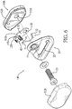
- a first embodiment, a second embodiment, a third embodiment, and a fourth embodiment of a guide ring sensor 1A, 1B in accordance with the present invention comprises a fixing seat 10A, 10B, a guide ring 20, an elastic member 30, and a sensing element 40.
- the guide ring sensor 1A, 1B further has a shell 50A, 50B.
- the fixing seat 10A, 10B has a body 11A, 11B, a connecting plate 12A, 12B, and a positioning hole 13A, 13B.
- the body 11A, 11B has a front surface, a first end, and a second end. The first end and the second end of the body 11A, 11B are formed on the front surface of the body 11A, 11B and opposite each other.
- the connecting plate 12A, 12B is mounted on the first end of the body 11A, 11B.
- the positioning hole 13A, 13B is formed through the body 11A, 11B adjacent to the second end of the body 11A, 11B.
- the fixing seat 10A, 10B has a positioning portion 14A, 14B.
- the positioning portion 14A, 14B is mounted on the first end of the body 11A, 11B near the connecting plate 12A, 12B and protrudes out of the front surface of the body 11A, 11B.
- the positioning portion 14A of the fixing seat 10A and the body 11A of the fixing seat 10A are integrated in one piece.
- the positioning portion 14A of the fixing seat 10A protrudes from the body 11A of the fixing seat 10A and is bent to the front surface of the body 11A.
- the positioning portion 14B of the fixing seat 10B is an independent component, is fixedly mounted on the body 11B of the fixing seat 10B, and extends out of the frond surface of the body 11B.
- the connecting plate 12A is an independent component and is fixedly mounted on the front surface of the body 11A.
- the connecting plate 12A extends out of the front surface of the body 11A.
- the connecting plate 12B of the fixing seat 10B and the body 11B of the fixing seat 10B are integrated in one piece, and the connecting plate 12B of the fixing seat 10B is bent to and extends out of the front surface of the body 11B.
- the guide ring 20 is pivoted on the fixing seat 10A, 10B by a positioning member 23.
- the guide ring 20 has an upper section, a lower section, a pivot hole 21, and a slot 22.
- the upper section of the guide ring 20 has a first side surface and a second side surface. The first side surface is formed on the upper section and faces the positioning portion 14A, 14B of the fixing seat 10A, 10B. The second side surface is opposite the first side surface of the upper section.
- the lower section of the guide ring 20 is deposited below the upper section of the guide ring 20.
- the pivot hole 21 is formed through the upper section of the guide ring 20.
- the slot 22 is formed through the lower section of the guide ring 20.
- the pivot hole 21 of the guide ring 20 is deposited above the slot 22 of the guide ring 20.
- the positioning member 23 is inserted through the pivot hole 21 of the guide ring 20 and the positioning hole 13A, 13B of the body 11A, 11B, and the guide ring 20 is rotatably mounted on the fixing seat 10A, 10B.
- the fixing seat 10A, 10B is fixedly mounted in a vehicle by the positioning member 23.
- a webbing 61 of a seat belt mechanism mounted in the vehicle is inserted through the slot 22 of the guide ring 20.
- a rear section 611 of the webbing 61 may be pulled to generate an oblique tension.
- the guide ring 20 may be pivoted on the positioning member 23 by the oblique tension. With reference to Fig. 8 , when the oblique tension is released, the webbing 60 may be moved to an initial position.
- the elastic member 30 is rotatably mounted on the body 11A, 11B of the fixing seat 10A, 10B.
- the elastic member 30 is connected to the guide ring 20 and may provide resilience to the guide ring 20 to restore the guide ring 20.
- the elastic member 30 has two ends, a positioning part 31, and a motion part 32.
- the positioning part 31 is formed on one of the two ends of the elastic member 30 and is positioned on the positioning portion 14A, 14B of the fixing seat 10A, 10B.
- the motion part 32 is formed on the other one of the two ends of the elastic member 30 and is connected to the second side surface of the upper section of the guide ring 20.
- the elastic member 30 provides resilience to the guide ring 20 to restore the guide ring 20.
- the sensing element 40 is mounted on the connecting plate 12A, 12B of the fixing seat 10A, 10B.
- the sensing element 40 has a sensing portion 41.
- the sensing portion 41 detects a pivoting angle change of the guide ring 20, and the sensing element 40 generates a signal corresponding to the pivoting angle change of the guide ring 20.
- the sensing element 40 may be a contact sensing element or a non-contact sensing element.
- the sensing element 40 may be a micro switch belonging to the contact sensing element.
- the sensing portion 41 of the sensing element 40 is selectively contacted by the guide ring 20 to switch.
- the guide ring 20 when the guide ring 20 is at the initial position by the resilience provided by the elastic member 30, the guide ring 20 contacts the sensing portion 41.
- the guide ring 20 may be pivoted without contacting the sensing portion 41 to escape a detection range of the sensing element 40.
- the sensing element 40 is not restricted to the contact sensing element.
- the shell 50A, 50B is mounted outside and around the fixing seat 10A, 10B, the guide ring 20, the elastic member 30, and the sensing element 40.
- the shell 50A, 50B has a bottom surface, a rear surface, an activity space, and an opening.
- the activity space is formed in the shell 50A, 50B.
- the opening is formed on the bottom surface of the shell 50A, 50B and communicates with the activity space of the shell 50A, 50B.
- the lower section of the guide ring 20 extends out of the opening of the shell 50A, 50B and is freely moveable.
- the positioning member 23 is inserted out of the rear surface of the shell 50A, 50B.
- the shell 50A is an integrated piece.
- the shell 50A has a back board 51A and the rear surface of the shell 50A is formed on the back board 51A, and the back board 51A has a bottom edge and an elongated hole 52A.
- the elongated hole 52A is formed on the bottom edge of the back board 51A and extends upwardly.
- the elongated hole 52A is in communication with the activity space of the shell 50A.
- the shell 50A covers the fixing seat 10A, the guide ring 20, the elastic member 30, and the sensing element 40 from top to down.
- the positioning member 23 is inserted through the elongated hole 52A.
- the shell 50B has a front cover 51B and a rear cover 52B.
- the rear cover 52B is mounted to the front cover 51B.
- the front cover 51B and the rear cover 52B are located outside the fixing seat 10B, the guide ring 20, the elastic member 30, and the sensing element 40.
- the shell 50B has a through hole 53B.
- the through hole 53B is formed through the rear cover 52B and communicates with the activity space of the shell 50B.
- the positioning member 23 is inserted through the through hole 53B.
- a second embodiment of the guide ring sensor 1A in Figs. 1 to 3 is applied to a seat belt mechanism in the vehicle.
- the guide ring sensor 1A is fixedly mounted in the vehicle by the positioning member 23 inserted through the guide ring 20 and the body 11A of the fixing seat 10A.
- the sensing element 40 is electrically connected to an alarm system in the vehicle.
- the webbing 61 pulled from a retractor 60 is inserted through the slot 22 of the guide ring 20 of the guide ring sensor 1A.
- a tongue 62 is mounted on the rear section 611 of the webbing 61.
- the rear section 611 of the webbing 61 is drooped vertically.
- the webbing 61 does not generate the oblique tension.
- the resilience provided by the elastic member 30 is forced on the guide ring 20 of the guide ring sensor 1A.
- the guide ring 20 contacts the sensing portion 41 of the sensing element 40.
- the sensing element 40 generates the signal to the alarm system.
- the alarm system generates a warning sound for reminding the driver or the passengers to fasten the seat belt.
- the webbing 61 does not pass through a front side of the torso of the driver or passenger.
- the tongue 62 mounted on the rear section 611 is inserted into a seat belt buckle 63.
- the oblique tension supplied by the webbing 61 is forced on the guide ring 20 and is insufficient.
- the pivoting angle change of the guide ring 20 is insufficient to lead the guide ring 20 to escape the detection range of the sensing element 40. Therefore, the sensing element 40 still generates the signal to the alarm system.
- the alarm system generates a warning sound for reminding the driver or the passengers to fasten the seat belt.
- the tongue 62 mounted on the webbing 61 is inserted into the seat belt buckle 63.
- the webbing 61 obliquely passes through the front side of the torso of the driver or passenger.
- the oblique tension generated by the rear section 611 of the webbing 61 pulls the guide ring 20 of the guide ring sensor 1A to pivot for an angle until the guide ring 20 escapes the detection range of the sensing element 40.
- the sensing element 40 generates the signal to the alarm system to stop the warning sound.
- the sensing element 40 and the guide ring 20 are combined for directly mounting on a predetermined mounting location for the guide ring in the vehicle and are electrically connected to the alarm system in the vehicle.
- the pivoting angle of the guide ring 20 may be detected to judge whether the driver or the passengers in the vehicle correctly use the seat belt mechanism or not, and then the guide ring sensor 1A, 1B may cooperate with the alarm system in the vehicle.
- the driver or any one of the passengers does not fasten the webbing 61 of the seat belt, it is hard to avoid triggering the alarm system or to restrain a system function by means of inserting an auxiliary tongue into the seat belt buckle 63 or by not passing the webbing 61 through the front side of the torso of the driver or passenger.
- the guide ring 20 When the webbing 61 is fastened correctly, the guide ring 20 is pulled by the oblique tension supplied by the webbing 61, and the guide ring 20 is pivoted to escape the detection range of the sensing element 40 for stopping a warning sound of the alarm system or recovering the system function. Therefore, the guide ring sensor 1A, 1B may promote the reliability of the seat belt in use.
Landscapes
- Engineering & Computer Science (AREA)
- Mechanical Engineering (AREA)
- Automation & Control Theory (AREA)
- Automotive Seat Belt Assembly (AREA)
- Seats For Vehicles (AREA)
Claims (11)
- Ein Führungsringsensor, umfassend einen Befestigungssitz (10A, 10B) und einen Führungsring (20), der an dem Befestigungssitz (10A, 10B) durch ein Positionierelement (23) schwenkbar gelagert ist, wobei der Führungsring (20) einen oberen Abschnitt, einen unteren Abschnitt, der unter dem oberen Abschnitt des Führungsrings (20) angeordnet ist, ein Schwenkloch (21), das durch den oberen Abschnitt des Führungsrings (20) hindurch ausgebildet ist, und einen Schlitz (22), der durch den unteren Abschnitt des Führungsrings (20) hindurch ausgebildet ist, aufweist, wobei das Schwenkloch (21) des Führungsrings (20) über dem Schlitz (22) des Führungsrings (20) angeordnet ist, das Positionierelement (23) durch das Schwenkloch (21) des Führungsrings (20) hindurch eingesetzt ist und der Führungsring (20) drehbar an dem Befestigungssitz (10A, 10B) montiert ist, dadurch gekennzeichnet, dass der Führungsringsensor umfasst:
einen Befestigungssitz (10A, 10B), umfassendeinen Körper (11A, 11B), umfassend
eine vordere Fläche,
wobei ein erstes Ende des Körpers (11A, 11B) an der vorderen Fläche des Körpers (11A, 11B) ausgebildet ist,
wobei ein zweites Ende an der vorderen Fläche des Körpers (11A, 11B) ausgebildet ist und entgegengesetzt zu dem ersten Ende des Körpers (11A, 11B) ist,eine Verbindungsplatte (12A, 12B), die an dem ersten Ende des Körpers (11A, 11B) montiert ist, undein Positionierloch (13A, 13B), das durch den Körper (11A, 11B) hindurch benachbart zu dem zweiten Ende des Körpers (11A, 11B) ausgebildet ist, wobei das Positionierelement (23) durch das Positionierloch (13A, 13B) des Körpers (11A, 11B) hindurch eingesetzt ist,ein elastisches Element (30), das an dem Körper (11A, 11B) des Befestigungssitzes (10A, 10B) montiert ist und mit dem Führungsring (20) verbunden ist, wobei das elastische Element (30) dem Führungsring (20) Elastizität bereitstellt, undein Messelement (40), das an der Verbindungsplatte (12A, 12B) des Befestigungssitzes (10A, 10B) montiert ist und einen Messabschnitt (41) umfasst, wobei der Messabschnitt (41) eine Schwenkwinkeländerung des Führungsrings (20) detektiert und das Messelement (40) ein Signal erzeugt, das der Schwenkwinkeländerung des Führungsrings (20) entspricht. - Der Führungsringsensor nach Anspruch 1, wobei
eine Schale (50A, 50B), die außerhalb des Befestigungssitzes (10A, 10B), des Führungsrings (20), des elastischen Elements (30) und des Messelements (40) und um diese herum montiert ist und umfasst:eine untere Fläche,eine hintere Fläche,einen Raum, der in der Schale (20) ausgebildet ist, undeine Öffnung, die an der unteren Fläche der Schale (50A, 50B) ausgebildet ist und mit dem Raum kommuniziert, wobei sich der untere Abschnitt des Führungsrings (20) aus der Öffnung der Schale (50A, 50B) heraus erstreckt und frei bewegbar ist, und das Positionierelement (23) aus der hinteren Fläche der Schale (50A, 50B) heraus eingesetzt ist. - Der Führungsringsensor nach Anspruch 2, wobeider Befestigungssitz (10A, 10B) umfasst:
einen Positionierabschnitt (14A, 14B), der an dem ersten Ende des Körpers (11A, 11B) montiert ist und aus der vorderen Fläche des Körpers (11A, 11B) heraus hervorsteht,der obere Abschnitt des Führungsrings (20) umfasst:
eine erste Seitenfläche, die an dem oberen Abschnitt ausgebildet ist und dem Positionierabschnitt (14A, 14B) des Befestigungssitzes (10A, 10B) zugewandt ist, und
eine zweite Seitenfläche entgegengesetzt zu der ersten Seitenfläche des oberen Abschnitts, unddas elastische Element (30) umfasst:
zwei Enden,
einen Positionierteil (31), der an einem der beiden Enden des elastischen Elements (30) ausgebildet ist und an dem Positionierabschnitt (14A, 14B) des Befestigungssitzes (10A, 10B) positioniert ist, und
einen Bewegungsteil (32), der an einem anderen der beiden Enden des elastischen Elements (30) ausgebildet ist und mit der zweiten Seitenfläche des oberen Abschnitts des Führungsrings (20) verbunden ist, wobei das elastische Element (30) dem Führungsring (20) Elastizität bereitstellt. - Der Führungsringsensor nach Anspruch 3, wobei der Positionierabschnitt (14A) des Befestigungssitzes (10A) und der Körper (11A) des Befestigungssitzes (10A) in einem Stück integriert sind und der Positionierabschnitt (14A) des Befestigungssitzes (10A) von dem Körper (11A) des Befestigungssitzes (10A) hervorsteht und zu der vorderen Fläche des Körpers (11A) gebogen ist.
- Der Führungsringsensor nach Anspruch 3, wobei der Positionierabschnitt (14B) des Befestigungssitzes (10B) ein unabhängiges Bauelement ist, fest an dem Körper (11B) des Befestigungssitzes (10B) montiert ist und sich aus der vorderen Fläche des Körpers (11B) heraus erstreckt.
- Der Führungsringsensor nach einem der Ansprüche 3 bis 5, wobei die Verbindungsplatte (12A) ein unabhängiges Bauelement ist und fest an der vorderen Fläche des Körpers (11A) montiert ist.
- Der Führungsringsensor nach einem der Ansprüche 3 bis 5, wobei die Verbindungsplatte (12B) des Befestigungssitzes (10B) und der Körper (11B) des Befestigungssitzes (10B) in einem Stück integriert sind und die Verbindungsplatte (12B) des Befestigungssitzes (10B) zu der vorderen Fläche des Körpers (11B) gebogen ist und sich aus dieser heraus erstreckt.
- Der Führungsringsensor nach einem der Ansprüche 3 bis 5, wobei das Messelement (40) ein Mikroschalter ist und der Messabschnitt (41) des Messelements (40) zum Schalten von dem Führungsring (20) wahlweise kontaktiert wird.
- Der Führungsringsensor nach einem der Ansprüche 3 bis 5, wobei die Schale (50A) ein integriertes Stück ist, die Schale (50A) eine Rückwand (51A) umfasst und die hintere Fläche der Schale (50A) an der Rückwand (51A) ausgebildet ist, und die Rückwand (51A) einen unteren Rand und ein Langloch (52A) umfasst, und das Langloch (52A) an dem unteren Rand der Rückwand (51A) ausgebildet ist und sich nach oben erstreckt, und die Schale (50A) den Befestigungssitz (10A, 10B), den Führungsring (20), das elastische Element (30) und das Messelement (40) von oben nach unten bedeckt, und das Positionierelement (23) durch das Langloch (52A) hindurch eingesetzt ist.
- Der Führungsringsensor nach Anspruch 9, wobei das Messelement (40) ein Mikroschalter ist und der Messabschnitt (41) des Messelements (40) zum Schalten von dem Führungsring (20) wahlweise kontaktiert wird.
- Der Führungsringsensor nach einem der Ansprüche 3 bis 5, wobei die Schale (50B) eine vordere Abdeckung (51B) und eine hintere Abdeckung (52B) umfasst, die an der vorderen Abdeckung (51B) montiert ist, die vordere Abdeckung (51B) und die hintere Abdeckung (52B) außerhalb des Befestigungssitzes (10A, 10B), des Führungsrings (20), des elastischen Elements (30) und des Messelements (40) angeordnet sind, die Schale (50B) ein Durchgangsloch (53B) umfasst, das durch die hintere Abdeckung (52B) hindurch ausgebildet ist, und das Positionierelement (23) durch das Durchgangsloch (53B) hindurch eingesetzt ist.
Priority Applications (1)
| Application Number | Priority Date | Filing Date | Title |
|---|---|---|---|
| PL18168705T PL3395620T3 (pl) | 2017-04-24 | 2018-04-23 | Czujnik pierścienia prowadzącego |
Applications Claiming Priority (1)
| Application Number | Priority Date | Filing Date | Title |
|---|---|---|---|
| TW106113639 | 2017-04-24 |
Publications (2)
| Publication Number | Publication Date |
|---|---|
| EP3395620A1 EP3395620A1 (de) | 2018-10-31 |
| EP3395620B1 true EP3395620B1 (de) | 2019-09-04 |
Family
ID=62046719
Family Applications (1)
| Application Number | Title | Priority Date | Filing Date |
|---|---|---|---|
| EP18168705.4A Active EP3395620B1 (de) | 2017-04-24 | 2018-04-23 | Führungsringsensor |
Country Status (6)
| Country | Link |
|---|---|
| US (1) | US10583804B2 (de) |
| EP (1) | EP3395620B1 (de) |
| JP (1) | JP6667569B2 (de) |
| ES (1) | ES2747924T3 (de) |
| PL (1) | PL3395620T3 (de) |
| TW (1) | TWI660330B (de) |
Families Citing this family (8)
| Publication number | Priority date | Publication date | Assignee | Title |
|---|---|---|---|---|
| TWI660330B (zh) * | 2017-04-24 | 2019-05-21 | 王亮雄 | 上環織帶感測器 |
| JP6943735B2 (ja) * | 2017-11-17 | 2021-10-06 | ダイハツ工業株式会社 | シートベルトリマインダ装置 |
| ES2799474A1 (es) * | 2019-06-12 | 2020-12-17 | Olice Solutions S L | Dispositivo de control de cinturones de seguridad |
| DE102019135914A1 (de) * | 2019-12-31 | 2021-07-01 | Zf Automotive Germany Gmbh | Verfahren für ein Sicherheitsgurtsystem, Sicherheitsgurtsystem für ein Fahrzeug und Fahrzeug mit einem Sicherheitsgurtsystem |
| WO2022132107A1 (en) * | 2020-12-16 | 2022-06-23 | Arge-Emre Makina Tasarim Sanayi Ticaret Ltd. Sti. | A seat belt misuse detection method and system thereof |
| KR102517770B1 (ko) * | 2021-10-18 | 2023-04-04 | 이귀동 | 안전벨트 정상 착용 감지 시스템 |
| DE102022107264B4 (de) | 2022-03-28 | 2023-11-02 | Autoliv Development Ab | Umlenkeinrichtung und Sicherheitsgurteinrichtung |
| DE102023131933B3 (de) * | 2023-11-16 | 2024-11-07 | Autoliv Development Ab | Umlenkeinrichtung zur Umlenkung eines Kraftfahrzeug-Sicherheitsgurtes |
Family Cites Families (18)
| Publication number | Priority date | Publication date | Assignee | Title |
|---|---|---|---|---|
| US645053A (en) * | 1899-11-22 | 1900-03-13 | Alfred H Alexander | Hinged dashboard. |
| US4511097A (en) * | 1981-12-14 | 1985-04-16 | Nippon Soken, Inc. | Automobile seat belt winding device |
| JPS58185350A (ja) * | 1982-04-26 | 1983-10-29 | Nippon Soken Inc | シ−トベルト巻取り装置 |
| JPH04189647A (ja) * | 1990-11-22 | 1992-07-08 | Nissan Motor Co Ltd | 自動車のシートベルト装置 |
| US5732974A (en) * | 1997-03-03 | 1998-03-31 | Trw Vehicle Safety Systems Inc. | Seat belt system energy management device replacement indicator |
| US6340209B1 (en) * | 1997-09-12 | 2002-01-22 | Nsk Ltd. | Vehicle body acceleration sensor for seat belts |
| WO2001087676A2 (en) * | 2000-05-12 | 2001-11-22 | Siemens Automotive Corporation | Seat belt force sensor system |
| JP2003175796A (ja) * | 2001-12-10 | 2003-06-24 | Takata Corp | シートベルト張力測定装置 |
| US20040232670A1 (en) * | 2002-03-12 | 2004-11-25 | Trw Vehicle Safety Systems Inc. | Apparatus for measuring tension in seat belt webbing |
| DE10217227C1 (de) * | 2002-04-18 | 2003-05-22 | Autoliv Dev | Für eine Gurtkraftmessung eingerichtete Befestigungsanordnung für ein Sicherheitsgurtschloß |
| US20080048858A1 (en) * | 2006-08-25 | 2008-02-28 | Lueth Jacquelynn R | Seatbelt fault alert system |
| DE102007030575B4 (de) * | 2007-07-02 | 2020-07-23 | Zf Automotive Germany Gmbh | Umlenkbeschlag für einen Sicherheitsgurt und Baugruppe mit einem Umlenkbeschlag und einer Erfassungsvorrichtung für die Gurtbandauszugslänge |
| KR101148166B1 (ko) * | 2009-10-29 | 2012-05-23 | 아우토리브 디벨롭먼트 아베 | 차량용 안전벨트의 버클 홀스위치 |
| KR101148167B1 (ko) * | 2009-10-29 | 2012-05-23 | 아우토리브 디벨롭먼트 아베 | 차량용 안전벨트의 버클구조 |
| GB2481586B (en) * | 2010-06-28 | 2012-09-26 | Nissan Motor Mfg Uk Ltd | Seatbelt buckle assembly |
| EP2899062A1 (de) * | 2014-01-28 | 2015-07-29 | Ford Otomotiv Sanayi Anonim Sirketi | Sicherheitsgurterkennungsvorrichtung zur Erkennung des zugeschnallten Zustands für einen Fahrersitz |
| TWI660330B (zh) * | 2017-04-24 | 2019-05-21 | 王亮雄 | 上環織帶感測器 |
| JP2019185350A (ja) * | 2018-04-09 | 2019-10-24 | 東芝メモリ株式会社 | メモリシステム及びメモリシステムの制御方法 |
-
2018
- 2018-04-03 TW TW107111959A patent/TWI660330B/zh not_active IP Right Cessation
- 2018-04-09 JP JP2018074691A patent/JP6667569B2/ja not_active Expired - Fee Related
- 2018-04-20 US US15/958,361 patent/US10583804B2/en active Active
- 2018-04-23 EP EP18168705.4A patent/EP3395620B1/de active Active
- 2018-04-23 PL PL18168705T patent/PL3395620T3/pl unknown
- 2018-04-23 ES ES18168705T patent/ES2747924T3/es active Active
Non-Patent Citations (1)
| Title |
|---|
| None * |
Also Published As
| Publication number | Publication date |
|---|---|
| US20180304850A1 (en) | 2018-10-25 |
| TWI660330B (zh) | 2019-05-21 |
| ES2747924T3 (es) | 2020-03-12 |
| EP3395620A1 (de) | 2018-10-31 |
| JP2018184161A (ja) | 2018-11-22 |
| US10583804B2 (en) | 2020-03-10 |
| PL3395620T3 (pl) | 2020-03-31 |
| JP6667569B2 (ja) | 2020-03-18 |
| TW201839731A (zh) | 2018-11-01 |
Similar Documents
| Publication | Publication Date | Title |
|---|---|---|
| EP3395620B1 (de) | Führungsringsensor | |
| JP2004514901A (ja) | ウェビング張力センサ | |
| US6854415B2 (en) | Seat belt tension sensing device | |
| JPH1076911A (ja) | 取外し可能なシート、特に助手席シートを有する車両用安全装置 | |
| JP2010083175A (ja) | 助手席用エアバッグ装置 | |
| US5760684A (en) | Device for promtping use of vehicle seatbelts | |
| US6522257B1 (en) | Device for recognition of a child-restraint seat attached to a vehicle seat | |
| EP1783008A3 (de) | Vorrichtung zur Kollisionserkennung für ein Fahrzeug | |
| US20140028075A1 (en) | Retractor Mounted Belt Tension Sensor | |
| EP2021213B1 (de) | Spannungsanzeiger | |
| US20120326486A1 (en) | Apparatus for automatically locking and unlocking a vehicle seat belt | |
| US7007976B2 (en) | Seatbelt lock casing with an integrated force-sensing device | |
| EP1652735A1 (de) | Vorrichtung zur Festellung des Zustands der Verwendung eines Becken- und Schultergurtes eines Fahrzeugsitzes | |
| CN110103876B (zh) | 安全保障系统及具有该安全保障系统的儿童汽车座、汽车 | |
| US5141193A (en) | Mounting system for a deceleration sensor | |
| CN108860053B (zh) | 上环织带感测器 | |
| JP2001187559A (ja) | シートベルト装置 | |
| JP2002337656A (ja) | バックル装置 | |
| KR20140029078A (ko) | 옷이 낌을 알려주는 자동차 문의 안전경보장치 | |
| JP7746639B2 (ja) | バックル、判定システム及び判定方法 | |
| TR202020693A1 (tr) | Emni̇yet kemeri̇ hatali kullanim önleme si̇stemi̇ ve buna i̇li̇şki̇n bi̇r yöntem | |
| JP2020062984A (ja) | シートベルトウェビング及びシートベルト装置 | |
| KR101749655B1 (ko) | 웨빙클립 감지모듈 및 이를 포함하는 시트벨트용 리트랙터 | |
| JP3924144B2 (ja) | バックル装置 | |
| CN119687775A (zh) | 在车辆中激活安全设备的接触识别系统 |
Legal Events
| Date | Code | Title | Description |
|---|---|---|---|
| PUAI | Public reference made under article 153(3) epc to a published international application that has entered the european phase |
Free format text: ORIGINAL CODE: 0009012 |
|
| STAA | Information on the status of an ep patent application or granted ep patent |
Free format text: STATUS: REQUEST FOR EXAMINATION WAS MADE |
|
| 17P | Request for examination filed |
Effective date: 20180911 |
|
| AK | Designated contracting states |
Kind code of ref document: A1 Designated state(s): AL AT BE BG CH CY CZ DE DK EE ES FI FR GB GR HR HU IE IS IT LI LT LU LV MC MK MT NL NO PL PT RO RS SE SI SK SM TR |
|
| AX | Request for extension of the european patent |
Extension state: BA ME |
|
| GRAP | Despatch of communication of intention to grant a patent |
Free format text: ORIGINAL CODE: EPIDOSNIGR1 |
|
| STAA | Information on the status of an ep patent application or granted ep patent |
Free format text: STATUS: GRANT OF PATENT IS INTENDED |
|
| RIC1 | Information provided on ipc code assigned before grant |
Ipc: B60R 22/48 20060101AFI20190208BHEP Ipc: B60R 22/19 20060101ALI20190208BHEP Ipc: B60R 22/18 20060101ALI20190208BHEP |
|
| INTG | Intention to grant announced |
Effective date: 20190227 |
|
| GRAS | Grant fee paid |
Free format text: ORIGINAL CODE: EPIDOSNIGR3 |
|
| GRAA | (expected) grant |
Free format text: ORIGINAL CODE: 0009210 |
|
| STAA | Information on the status of an ep patent application or granted ep patent |
Free format text: STATUS: THE PATENT HAS BEEN GRANTED |
|
| AK | Designated contracting states |
Kind code of ref document: B1 Designated state(s): AL AT BE BG CH CY CZ DE DK EE ES FI FR GB GR HR HU IE IS IT LI LT LU LV MC MK MT NL NO PL PT RO RS SE SI SK SM TR |
|
| REG | Reference to a national code |
Ref country code: GB Ref legal event code: FG4D |
|
| REG | Reference to a national code |
Ref country code: CH Ref legal event code: EP |
|
| REG | Reference to a national code |
Ref country code: AT Ref legal event code: REF Ref document number: 1174913 Country of ref document: AT Kind code of ref document: T Effective date: 20190915 |
|
| REG | Reference to a national code |
Ref country code: NL Ref legal event code: FP |
|
| REG | Reference to a national code |
Ref country code: SE Ref legal event code: TRGR |
|
| REG | Reference to a national code |
Ref country code: DE Ref legal event code: R096 Ref document number: 602018000561 Country of ref document: DE |
|
| REG | Reference to a national code |
Ref country code: IE Ref legal event code: FG4D |
|
| REG | Reference to a national code |
Ref country code: RO Ref legal event code: EPE |
|
| REG | Reference to a national code |
Ref country code: LT Ref legal event code: MG4D |
|
| PG25 | Lapsed in a contracting state [announced via postgrant information from national office to epo] |
Ref country code: HR Free format text: LAPSE BECAUSE OF FAILURE TO SUBMIT A TRANSLATION OF THE DESCRIPTION OR TO PAY THE FEE WITHIN THE PRESCRIBED TIME-LIMIT Effective date: 20190904 Ref country code: NO Free format text: LAPSE BECAUSE OF FAILURE TO SUBMIT A TRANSLATION OF THE DESCRIPTION OR TO PAY THE FEE WITHIN THE PRESCRIBED TIME-LIMIT Effective date: 20191204 Ref country code: FI Free format text: LAPSE BECAUSE OF FAILURE TO SUBMIT A TRANSLATION OF THE DESCRIPTION OR TO PAY THE FEE WITHIN THE PRESCRIBED TIME-LIMIT Effective date: 20190904 Ref country code: BG Free format text: LAPSE BECAUSE OF FAILURE TO SUBMIT A TRANSLATION OF THE DESCRIPTION OR TO PAY THE FEE WITHIN THE PRESCRIBED TIME-LIMIT Effective date: 20191204 Ref country code: LT Free format text: LAPSE BECAUSE OF FAILURE TO SUBMIT A TRANSLATION OF THE DESCRIPTION OR TO PAY THE FEE WITHIN THE PRESCRIBED TIME-LIMIT Effective date: 20190904 |
|
| PG25 | Lapsed in a contracting state [announced via postgrant information from national office to epo] |
Ref country code: RS Free format text: LAPSE BECAUSE OF FAILURE TO SUBMIT A TRANSLATION OF THE DESCRIPTION OR TO PAY THE FEE WITHIN THE PRESCRIBED TIME-LIMIT Effective date: 20190904 Ref country code: GR Free format text: LAPSE BECAUSE OF FAILURE TO SUBMIT A TRANSLATION OF THE DESCRIPTION OR TO PAY THE FEE WITHIN THE PRESCRIBED TIME-LIMIT Effective date: 20191205 Ref country code: AL Free format text: LAPSE BECAUSE OF FAILURE TO SUBMIT A TRANSLATION OF THE DESCRIPTION OR TO PAY THE FEE WITHIN THE PRESCRIBED TIME-LIMIT Effective date: 20190904 Ref country code: LV Free format text: LAPSE BECAUSE OF FAILURE TO SUBMIT A TRANSLATION OF THE DESCRIPTION OR TO PAY THE FEE WITHIN THE PRESCRIBED TIME-LIMIT Effective date: 20190904 |
|
| REG | Reference to a national code |
Ref country code: ES Ref legal event code: FG2A Ref document number: 2747924 Country of ref document: ES Kind code of ref document: T3 Effective date: 20200312 |
|
| REG | Reference to a national code |
Ref country code: AT Ref legal event code: MK05 Ref document number: 1174913 Country of ref document: AT Kind code of ref document: T Effective date: 20190904 |
|
| PG25 | Lapsed in a contracting state [announced via postgrant information from national office to epo] |
Ref country code: PT Free format text: LAPSE BECAUSE OF FAILURE TO SUBMIT A TRANSLATION OF THE DESCRIPTION OR TO PAY THE FEE WITHIN THE PRESCRIBED TIME-LIMIT Effective date: 20200106 Ref country code: EE Free format text: LAPSE BECAUSE OF FAILURE TO SUBMIT A TRANSLATION OF THE DESCRIPTION OR TO PAY THE FEE WITHIN THE PRESCRIBED TIME-LIMIT Effective date: 20190904 Ref country code: AT Free format text: LAPSE BECAUSE OF FAILURE TO SUBMIT A TRANSLATION OF THE DESCRIPTION OR TO PAY THE FEE WITHIN THE PRESCRIBED TIME-LIMIT Effective date: 20190904 |
|
| PG25 | Lapsed in a contracting state [announced via postgrant information from national office to epo] |
Ref country code: SM Free format text: LAPSE BECAUSE OF FAILURE TO SUBMIT A TRANSLATION OF THE DESCRIPTION OR TO PAY THE FEE WITHIN THE PRESCRIBED TIME-LIMIT Effective date: 20190904 Ref country code: IS Free format text: LAPSE BECAUSE OF FAILURE TO SUBMIT A TRANSLATION OF THE DESCRIPTION OR TO PAY THE FEE WITHIN THE PRESCRIBED TIME-LIMIT Effective date: 20200224 Ref country code: SK Free format text: LAPSE BECAUSE OF FAILURE TO SUBMIT A TRANSLATION OF THE DESCRIPTION OR TO PAY THE FEE WITHIN THE PRESCRIBED TIME-LIMIT Effective date: 20190904 |
|
| REG | Reference to a national code |
Ref country code: DE Ref legal event code: R097 Ref document number: 602018000561 Country of ref document: DE |
|
| PGFP | Annual fee paid to national office [announced via postgrant information from national office to epo] |
Ref country code: TR Payment date: 20200120 Year of fee payment: 3 |
|
| PLBE | No opposition filed within time limit |
Free format text: ORIGINAL CODE: 0009261 |
|
| STAA | Information on the status of an ep patent application or granted ep patent |
Free format text: STATUS: NO OPPOSITION FILED WITHIN TIME LIMIT |
|
| PG2D | Information on lapse in contracting state deleted |
Ref country code: IS |
|
| PG25 | Lapsed in a contracting state [announced via postgrant information from national office to epo] |
Ref country code: DK Free format text: LAPSE BECAUSE OF FAILURE TO SUBMIT A TRANSLATION OF THE DESCRIPTION OR TO PAY THE FEE WITHIN THE PRESCRIBED TIME-LIMIT Effective date: 20190904 Ref country code: IS Free format text: LAPSE BECAUSE OF FAILURE TO SUBMIT A TRANSLATION OF THE DESCRIPTION OR TO PAY THE FEE WITHIN THE PRESCRIBED TIME-LIMIT Effective date: 20200105 |
|
| PGFP | Annual fee paid to national office [announced via postgrant information from national office to epo] |
Ref country code: RO Payment date: 20200415 Year of fee payment: 3 Ref country code: ES Payment date: 20200611 Year of fee payment: 3 |
|
| 26N | No opposition filed |
Effective date: 20200605 |
|
| PGFP | Annual fee paid to national office [announced via postgrant information from national office to epo] |
Ref country code: PL Payment date: 20200417 Year of fee payment: 3 |
|
| PG25 | Lapsed in a contracting state [announced via postgrant information from national office to epo] |
Ref country code: MC Free format text: LAPSE BECAUSE OF FAILURE TO SUBMIT A TRANSLATION OF THE DESCRIPTION OR TO PAY THE FEE WITHIN THE PRESCRIBED TIME-LIMIT Effective date: 20190904 |
|
| PG25 | Lapsed in a contracting state [announced via postgrant information from national office to epo] |
Ref country code: LU Free format text: LAPSE BECAUSE OF NON-PAYMENT OF DUE FEES Effective date: 20200423 |
|
| REG | Reference to a national code |
Ref country code: BE Ref legal event code: MM Effective date: 20200430 |
|
| PG25 | Lapsed in a contracting state [announced via postgrant information from national office to epo] |
Ref country code: BE Free format text: LAPSE BECAUSE OF NON-PAYMENT OF DUE FEES Effective date: 20200430 |
|
| PG25 | Lapsed in a contracting state [announced via postgrant information from national office to epo] |
Ref country code: IE Free format text: LAPSE BECAUSE OF NON-PAYMENT OF DUE FEES Effective date: 20200423 |
|
| PG25 | Lapsed in a contracting state [announced via postgrant information from national office to epo] |
Ref country code: RO Free format text: LAPSE BECAUSE OF NON-PAYMENT OF DUE FEES Effective date: 20210423 Ref country code: LI Free format text: LAPSE BECAUSE OF NON-PAYMENT OF DUE FEES Effective date: 20210430 Ref country code: CH Free format text: LAPSE BECAUSE OF NON-PAYMENT OF DUE FEES Effective date: 20210430 |
|
| PG25 | Lapsed in a contracting state [announced via postgrant information from national office to epo] |
Ref country code: MT Free format text: LAPSE BECAUSE OF FAILURE TO SUBMIT A TRANSLATION OF THE DESCRIPTION OR TO PAY THE FEE WITHIN THE PRESCRIBED TIME-LIMIT Effective date: 20190904 Ref country code: CY Free format text: LAPSE BECAUSE OF FAILURE TO SUBMIT A TRANSLATION OF THE DESCRIPTION OR TO PAY THE FEE WITHIN THE PRESCRIBED TIME-LIMIT Effective date: 20190904 |
|
| REG | Reference to a national code |
Ref country code: ES Ref legal event code: FD2A Effective date: 20220629 |
|
| PG25 | Lapsed in a contracting state [announced via postgrant information from national office to epo] |
Ref country code: MK Free format text: LAPSE BECAUSE OF FAILURE TO SUBMIT A TRANSLATION OF THE DESCRIPTION OR TO PAY THE FEE WITHIN THE PRESCRIBED TIME-LIMIT Effective date: 20190904 |
|
| PG25 | Lapsed in a contracting state [announced via postgrant information from national office to epo] |
Ref country code: ES Free format text: LAPSE BECAUSE OF NON-PAYMENT OF DUE FEES Effective date: 20210424 |
|
| PGFP | Annual fee paid to national office [announced via postgrant information from national office to epo] |
Ref country code: FR Payment date: 20230307 Year of fee payment: 6 |
|
| PG25 | Lapsed in a contracting state [announced via postgrant information from national office to epo] |
Ref country code: PL Free format text: LAPSE BECAUSE OF NON-PAYMENT OF DUE FEES Effective date: 20210423 |
|
| PGFP | Annual fee paid to national office [announced via postgrant information from national office to epo] |
Ref country code: SE Payment date: 20230315 Year of fee payment: 6 |
|
| PGFP | Annual fee paid to national office [announced via postgrant information from national office to epo] |
Ref country code: NL Payment date: 20230405 Year of fee payment: 6 |
|
| PGFP | Annual fee paid to national office [announced via postgrant information from national office to epo] |
Ref country code: CZ Payment date: 20230411 Year of fee payment: 6 |
|
| PG25 | Lapsed in a contracting state [announced via postgrant information from national office to epo] |
Ref country code: SI Free format text: LAPSE BECAUSE OF FAILURE TO SUBMIT A TRANSLATION OF THE DESCRIPTION OR TO PAY THE FEE WITHIN THE PRESCRIBED TIME-LIMIT Effective date: 20190904 |
|
| PGFP | Annual fee paid to national office [announced via postgrant information from national office to epo] |
Ref country code: GB Payment date: 20240202 Year of fee payment: 7 |
|
| PGFP | Annual fee paid to national office [announced via postgrant information from national office to epo] |
Ref country code: IT Payment date: 20240219 Year of fee payment: 7 |
|
| PGFP | Annual fee paid to national office [announced via postgrant information from national office to epo] |
Ref country code: DE Payment date: 20240206 Year of fee payment: 7 |
|
| REG | Reference to a national code |
Ref country code: SE Ref legal event code: EUG |
|
| REG | Reference to a national code |
Ref country code: NL Ref legal event code: MM Effective date: 20240501 |
|
| PG25 | Lapsed in a contracting state [announced via postgrant information from national office to epo] |
Ref country code: NL Free format text: LAPSE BECAUSE OF NON-PAYMENT OF DUE FEES Effective date: 20240501 |
|
| PG25 | Lapsed in a contracting state [announced via postgrant information from national office to epo] |
Ref country code: FR Free format text: LAPSE BECAUSE OF NON-PAYMENT OF DUE FEES Effective date: 20240430 |
|
| PG25 | Lapsed in a contracting state [announced via postgrant information from national office to epo] |
Ref country code: CZ Free format text: LAPSE BECAUSE OF NON-PAYMENT OF DUE FEES Effective date: 20240423 |
|
| PG25 | Lapsed in a contracting state [announced via postgrant information from national office to epo] |
Ref country code: NL Free format text: LAPSE BECAUSE OF NON-PAYMENT OF DUE FEES Effective date: 20240501 Ref country code: FR Free format text: LAPSE BECAUSE OF NON-PAYMENT OF DUE FEES Effective date: 20240430 Ref country code: CZ Free format text: LAPSE BECAUSE OF NON-PAYMENT OF DUE FEES Effective date: 20240423 |
|
| PG25 | Lapsed in a contracting state [announced via postgrant information from national office to epo] |
Ref country code: SE Free format text: LAPSE BECAUSE OF NON-PAYMENT OF DUE FEES Effective date: 20240424 |
|
| REG | Reference to a national code |
Ref country code: DE Ref legal event code: R119 Ref document number: 602018000561 Country of ref document: DE |
|
| GBPC | Gb: european patent ceased through non-payment of renewal fee |
Effective date: 20250423 |
|
| PG25 | Lapsed in a contracting state [announced via postgrant information from national office to epo] |
Ref country code: DE Free format text: LAPSE BECAUSE OF NON-PAYMENT OF DUE FEES Effective date: 20251104 |
|
| PG25 | Lapsed in a contracting state [announced via postgrant information from national office to epo] |
Ref country code: GB Free format text: LAPSE BECAUSE OF NON-PAYMENT OF DUE FEES Effective date: 20250423 |