EP3395486B1 - Funkenerosionsmaschine und funkenerosionsbearbeitungssystem - Google Patents
Funkenerosionsmaschine und funkenerosionsbearbeitungssystem Download PDFInfo
- Publication number
- EP3395486B1 EP3395486B1 EP18169482.9A EP18169482A EP3395486B1 EP 3395486 B1 EP3395486 B1 EP 3395486B1 EP 18169482 A EP18169482 A EP 18169482A EP 3395486 B1 EP3395486 B1 EP 3395486B1
- Authority
- EP
- European Patent Office
- Prior art keywords
- workpiece
- lifting mechanism
- electrical discharge
- core
- upper nozzle
- Prior art date
- Legal status (The legal status is an assumption and is not a legal conclusion. Google has not performed a legal analysis and makes no representation as to the accuracy of the status listed.)
- Active
Links
Images





Classifications
-
- B—PERFORMING OPERATIONS; TRANSPORTING
- B23—MACHINE TOOLS; METAL-WORKING NOT OTHERWISE PROVIDED FOR
- B23H—WORKING OF METAL BY THE ACTION OF A HIGH CONCENTRATION OF ELECTRIC CURRENT ON A WORKPIECE USING AN ELECTRODE WHICH TAKES THE PLACE OF A TOOL; SUCH WORKING COMBINED WITH OTHER FORMS OF WORKING OF METAL
- B23H7/00—Processes or apparatus applicable to both electrical discharge machining and electrochemical machining
- B23H7/02—Wire-cutting
- B23H7/06—Control of the travel curve of the relative movement between electrode and workpiece
- B23H7/065—Electric circuits specially adapted therefor
-
- B—PERFORMING OPERATIONS; TRANSPORTING
- B23—MACHINE TOOLS; METAL-WORKING NOT OTHERWISE PROVIDED FOR
- B23H—WORKING OF METAL BY THE ACTION OF A HIGH CONCENTRATION OF ELECTRIC CURRENT ON A WORKPIECE USING AN ELECTRODE WHICH TAKES THE PLACE OF A TOOL; SUCH WORKING COMBINED WITH OTHER FORMS OF WORKING OF METAL
- B23H11/00—Auxiliary apparatus or details, not otherwise provided for
- B23H11/003—Mounting of workpieces, e.g. working-tables
-
- B—PERFORMING OPERATIONS; TRANSPORTING
- B23—MACHINE TOOLS; METAL-WORKING NOT OTHERWISE PROVIDED FOR
- B23H—WORKING OF METAL BY THE ACTION OF A HIGH CONCENTRATION OF ELECTRIC CURRENT ON A WORKPIECE USING AN ELECTRODE WHICH TAKES THE PLACE OF A TOOL; SUCH WORKING COMBINED WITH OTHER FORMS OF WORKING OF METAL
- B23H7/00—Processes or apparatus applicable to both electrical discharge machining and electrochemical machining
- B23H7/02—Wire-cutting
-
- B—PERFORMING OPERATIONS; TRANSPORTING
- B23—MACHINE TOOLS; METAL-WORKING NOT OTHERWISE PROVIDED FOR
- B23H—WORKING OF METAL BY THE ACTION OF A HIGH CONCENTRATION OF ELECTRIC CURRENT ON A WORKPIECE USING AN ELECTRODE WHICH TAKES THE PLACE OF A TOOL; SUCH WORKING COMBINED WITH OTHER FORMS OF WORKING OF METAL
- B23H1/00—Electrical discharge machining, i.e. removing metal with a series of rapidly recurring electrical discharges between an electrode and a workpiece in the presence of a fluid dielectric
- B23H1/02—Electric circuits specially adapted therefor, e.g. power supply, control, preventing short circuits or other abnormal discharges
-
- B—PERFORMING OPERATIONS; TRANSPORTING
- B23—MACHINE TOOLS; METAL-WORKING NOT OTHERWISE PROVIDED FOR
- B23H—WORKING OF METAL BY THE ACTION OF A HIGH CONCENTRATION OF ELECTRIC CURRENT ON A WORKPIECE USING AN ELECTRODE WHICH TAKES THE PLACE OF A TOOL; SUCH WORKING COMBINED WITH OTHER FORMS OF WORKING OF METAL
- B23H7/00—Processes or apparatus applicable to both electrical discharge machining and electrochemical machining
- B23H7/14—Electric circuits specially adapted therefor, e.g. power supply
- B23H7/20—Electric circuits specially adapted therefor, e.g. power supply for program control, e.g. adaptive
-
- G—PHYSICS
- G05—CONTROLLING; REGULATING
- G05B—CONTROL OR REGULATING SYSTEMS IN GENERAL; FUNCTIONAL ELEMENTS OF SUCH SYSTEMS; MONITORING OR TESTING ARRANGEMENTS FOR SUCH SYSTEMS OR ELEMENTS
- G05B2219/00—Program-control systems
- G05B2219/30—Nc systems
- G05B2219/45—Nc applications
- G05B2219/45043—EDM machine, wire cutting
Definitions
- the present invention relates to a wire electrical discharge machine and a wire electrical discharge machining system for use in performing electrical discharge machining on a workpiece set on a work table.
- Japanese Laid-Open Patent Publication No. 03-196919 discloses a core removal method comprising the steps of suctioning, by means of a suctioning face of a core retainer, a core that has been trapped in a lower arm moving a table with the core being suctioned so as to convey the core to a position away from the top of the lower arm, and dropping the core by stopping suction.
- US 5 94 5009 A describes a means for spark erosion of workpiece including an electrode disc or a wire electrode as a machining tool. This document also describes a machine according to the preamble of claim 1.
- JP S61 8224 A describes a method of using a magnetic chuck to remove a cutout portion from the workpiece, the latter remaining on the work table for further processing.
- EP 3 360 636 A1 was published on 15 August 2018 but enjoys a priority date of 13 February 2017 and constitutes a prior art document under Art. 54(3) EPC. Therein, a method is disclosed for separating parts from a base plate by a wire cutting apparatus.
- the wire cutting apparatus includes an electrode arranged in a horizontal direction and two nozzles of the wire electrode arranged at the same height.
- the core may fall into a lower nozzle.
- the technique disclosed in Japanese Laid-Open Patent Publication No. 03-196919 is not available to suck the core, and it is necessary to remove the core from the lower nozzle. Since the workpiece is located close to the lower nozzle, the workpiece needs to be detached from the work table in order to remove the core. Once the workpiece has been detached and is attached again, it is difficult to set the workpiece at the same position without error. Thus, there is a risk that the machining accuracy is deteriorated.
- the present invention has been devised to solve the above problem, it is therefore an object of the present invention to provide a wire electrical discharge machine as set out in claim 1 and a wire electrical discharge machining system as set out in claim 9.
- a wire electrical discharge machine for performing electrical discharge machining on a workpiece by applying voltage across an electrode gap between a wire electrode stretched between an upper nozzle and a lower nozzle and the workpiece to generate electrical discharges, comprising a lifting mechanism configured to move the workpiece in the travelling direction of the wire electrode.
- the present invention it is possible to remove the core without detaching the workpiece from the work table, hence suppress deterioration in the machining accuracy of the workpiece.
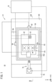
- FIGS. 1 and 2 are schematic views showing a configuration of a wire electrical discharge machining system 10 according to this embodiment.
- FIG. 1 is a view of the wire electrical discharge machining system 10 as seen from the top (positive Z-axis direction), and
- FIG. 2 is a partial sectional view taken along line II-II of FIG. 1 .
- the axis extending in the horizontal direction in FIG. 1 is defined as the X-axis
- the axis orthogonal to the X-axis on the horizontal plane is defined as the Y-axis
- the axis perpendicular to the X-axis and the Y-axis is defined as the Z-axis.
- the rightward is the positive X-axis direction
- the upward is the positive Y-axis direction
- the upward in FIG. 2 is the positive Z-axis direction.
- the wire electrical discharge machining system 10 includes a wire electrical discharge machine 12, an articulated robot 14 and a controller 16.
- the wire electrical discharge machine 12 is a machine tool that performs electrical discharge machining on a workpiece W by applying voltage to an electrode gap formed between a wire electrode 18 and the workpiece W to generate electrical discharge.
- the wire electrode 18 is formed of, for example, tungsten-based, copper alloy-based, brass-based metal or the like.
- the material of the workpiece W is, for example, a metal material such as an iron-based material or a carbide material.
- the wire electrical discharge machining system 10 includes a wire electrical discharge machine 12, an articulated robot 14 and a controller 16.
- the wire electrical discharge machine 12 includes a feed mechanism 20 for feeding the wire electrode 18.
- the feed mechanism 20 includes a wire bobbin 22 on which the wire electrode 18 is wound, a torque motor 24 for applying torque to the wire bobbin 22, a brake roller 26 for applying a braking force of friction on the wire electrode 18, a brake motor 28 for applying brake torque on the brake roller 26, a guide roller 30 for guiding the wire electrode 18, an upper wire guide 32 for guiding the wire electrode 18 above the workpiece W, a lower wire guide 34 for guiding the wire electrode 18 below the workpiece W and an unillustrated collecting mechanism for collecting the wire electrode 18.
- the wire electrode 18 can travel in the negative Z-axis direction between the upper wire guide 32 and the lower wire guide 34.
- the upper wire guide 32 and the lower wire guide 34 respectively have an upper nozzle 36 and a lower nozzle 38 for jetting a (dielectric) working fluid.
- the upper wire guide 32 and the upper nozzle 36 are supported by a Z-axis driving mechanism 40.
- the Z-axis driving mechanism 40 has an unillustrated Z-axis motor and can move the upper wire guide 32 and the upper nozzle 36 in the Z-axis direction.
- the lower wire guide 34 and the lower nozzle 38 are supported by an arm 42 extended from the collecting mechanism.
- the lower nozzle 38 has a drop detection sensor 44 for detecting that the core C formed in machining the workpiece W has fallen into the lower nozzle 38. When the core C falls into the lower nozzle 38 and comes into contact with the wire electrode 18, a current flows from the wire electrode 18 to the core C side, so that the current value between the wire electrode 18 and the workpiece W becomes smaller than usual.
- the core C fallen inside the lower nozzle 38 repeats contacting to and separating from the wire electrode 18, so that the current value between the wire electrode 18 and the workpiece W fluctuates.
- the drop detection sensor 44 monitors the decrease or fluctuation of the current value to detect that the core has fallen in the lower nozzle 38.
- the wire electrical discharge machine 12 includes a work-pan 50 capable of storing the working fluid such as deionized water or oil used for electrical discharge machining of the workpiece W.
- a work table 52 on which the workpiece W is set is installed in the work-pan 50.
- the workpiece W is held by a retainer 54a of a jig 54 so as not to be movable relative to the jig 54 and is fixed to the work table 52 by fixing the jig 54 to a top plate 52a of the work table 52.
- the work-pan 50 is installed movably on a saddle 56 in the Y-axis direction.
- the work-pan 50 is joined integrally with an unillustrated nut on a ball screw so as to be able to move in the Y-axis direction as the screw shaft of the ball screw is driven to turn by a Y-axis motor 58.
- the saddle 56 is arranged on a bed 60, movably in the X-axis direction.
- the saddle 56 is joined integrally with a ball screw nut (not shown) so as to be able to move in the X-axis direction as the screw shaft of the ball screw is driven to turn by an X-axis motor 62.
- the work table 52 installed in the work-pan 50 moves together with the work-pan 50. As a result, the workpiece W placed on the work table 52 can move in the X-axis direction and the Y-axis direction with respect to the wire electrode 18.
- the work table 52 has a lifting mechanism 64 for moving the top plate 52a of the work table 52 in the Z-axis direction.
- the lifting mechanism 64 has an unillustrated lift motor or the like so as to move the top plate 52a of the work table 52 in the Z-axis direction by driving the lift motor. At this time, the workpiece W placed on the work table 52 also moves in the Z-axis direction together with the top plate 52a.
- the lifting mechanism 64 has a linear scale 66 for detecting a stroke of the top plate 52a of the work table 52.
- the articulated robot 14 is installed on a mount base 70 arranged adjacent to the bed 60.
- the articulated robot 14 changes workpieces W, collects the core C dropped in the lower nozzle 38 during machining the workpiece W and so on.
- the articulated robot 14 has a distance measuring sensor 72 attached as an end effector, moves the distance measuring sensor 72 above and below the workpiece W before machining to measure the distance to the workpiece W.
- the plate thickness of the workpiece W can be calculated from the thus measured distance between the distance measuring sensor 72 and the workpiece W.
- the controller 16 receives various pieces of information from the drop detection sensor 44, the linear scale 66 and the distance measuring sensor 72, and outputs command signals to control the articulated robot 14, the torque motor 24, the brake motor 28, the X-axis motor 62, the Y-axis motor 58, the Z-axis motor of the Z-axis driving mechanism 40 and the lifting mechanism 64.
- FIG. 3 is a block diagram showing a configuration of the controller 16.
- the controller 16 includes a storage unit 80 and a processing operation unit 82.
- the storage unit 80 has a numerical control (NC) program storage 84.
- the NC program storage 84 stores an NC program that specifies a machining shape of the workpiece W and the like.
- the processing operation unit 82 includes a machining control unit 86, a plate thickness calculator 90, a core drop determiner 92, a target lift calculator 94, a lifting mechanism control unit 96, a Z-axis drive (mechanism) control unit 98, a robot control unit 100 and an alarm control unit 102.
- the machining control unit 86 controls the feed mechanism 20 (the torque motor 24, the brake motor 28), the X-axis motor 62, the Y-axis motor 58 and the Z-axis motor of the Z-axis driving mechanism 40, so that the workpiece W is machined into a shape according to the NC program.
- the plate thickness calculator 90 calculates the thickness of the workpiece W using the distance between the distance measuring sensor 72 and the workpiece W.
- the core drop determiner 92 based on the information input from the drop detection sensor 44, determines whether or not the core C has dropped in the lower nozzle 38.
- the target lift calculator 94 calculates a target lift value of the workpiece W to be lifted by the lifting mechanism 64 using the calculated thickness of the workpiece W.
- the lifting mechanism control unit 96 in accordance with the target lift calculated by the target lift calculator 94, outputs command signals to the lifting mechanism 64 and performs position control of the workpiece W with respect to the Z-axis direction.
- the Z-axis drive control unit 98 outputs command signals to the Z-axis motor of the Z-axis driving mechanism 40 and performs position control of the upper wire guide 32 and the upper nozzle 36 with respect to the Z-axis direction.
- the robot control unit 100 outputs command signals to the articulated robot 14 to perform exchange control of workpieces W and collection control of the core C.
- the alarm control unit 102 outputs a command signal to the alarm unit 68 and notifies the operator via voice or screen display.
- the core C is fixed to the workpiece W so that the core C will not drop into the work-pan 50.
- the core C may fall from the workpiece W in some cases.
- a core C fallen in the work-pan 50 does not cause any problem, a small core C sometimes drops into the lower nozzle 38.
- the core C is collected by the articulated robot 14.
- the workpiece W since the workpiece W is set on the work table 52 and positioned near the lower nozzle 38, the workpiece W gives hindrance to collection of the core C by the articulated robot 14.
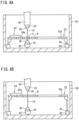
- FIGS. 4A and 4B are schematic sectional views showing the interior of the work-pan 50.
- FIG. 4A is a diagram showing a state where the workpiece W is being machined.
- FIG. 4B is a diagram showing a state where the workpiece W has been moved in the Z-axis direction by the lifting mechanism 64.
- the lifting mechanism 64 of the present embodiment sets the workpiece W by bringing its undersurface a predetermined distance close to the lower nozzle 38, as shown in FIG. 4A .
- the workpiece W is moved in the positive Z-axis direction as shown in FIG. 4B . Then, the core C can be collected by the articulated robot 14.
- FIG. 5A is a schematic diagram showing a state in which a core C of a relatively thin workpiece W has fallen in the lower nozzle 38.
- FIG. 5B is a schematic view showing a state in which a core C of a relatively thick workpiece W has fallen in the lower nozzle 38. As shown in FIG. 5A , when the workpiece W is relatively thin, the dropped core C enters into the lower nozzle 38 as a whole.
- the core C Since the distance D between the undersurface of the workpiece W and the position where the core C abuts against the lower nozzle 38 has been known beforehand, if the thickness T of the workpiece W is known, it is possible for the core C to completely go through the hole of the workpiece W by moving the workpiece W by, at least, the distance (T-D) in the positive Z-axis direction.
- FIG. 6 is a flowchart showing a processing flow of the core collection control performed in the controller 16.
- the core drop determiner 92 based on the information input from the drop detection sensor 44, determines whether or not the core C has fallen in the lower nozzle 38. When the core C has dropped in the lower nozzle 38, the control goes to step S2. When the core C has not fallen into the lower nozzle 38, the control is terminated.
- the target lift calculator 94 calculates the target lift of the workpiece W to be raised by the lifting mechanism 64, and the control proceeds to step S3.
- the target lift is a value, at least, greater than the aforementioned distance (T-D) and is calculated so that the end effector of the articulated robot 14 can operate between the workpiece W and the lower nozzle 38.
- the alarm control unit 102 determines whether or not the workpiece W interferes with the upper nozzle 36 from the thickness of the workpiece W and the target lift.
- the upper nozzle 36 is also moved in the positive Z-axis direction by the Z-axis driving mechanism 40.
- the workpiece W moves toward the upper nozzle 36 beyond the drive range of the Z-axis driving mechanism 40, and the workpiece W may interfere with the upper nozzle 36 in some cases.
- the alarm control unit 102 before the lifting mechanism 64 moves the workpiece W in the positive Z-axis direction, determines whether or not the workpiece W interferes with the upper nozzle 36 based on the thickness of the workpiece W and the target lift.
- step S4 the Z-axis drive control unit 98 computes a command signal based on the calculated target lift and outputs the command signal to the Z-axis driving mechanism 40. Then, the control proceeds to step S5. As a result, the upper nozzle 36 moves in the positive Z-axis direction.
- the lifting mechanism control unit 96 computes a command signal based on the calculated target lift, and outputs the command signal to the lifting mechanism 64, and the control goes to step S6. Thereby, the workpiece W moves in the positive Z-axis direction.
- the robot control unit 100 computes a command signal for causing the articulated robot 14 to collect the core C dropped in the lower nozzle 38, and outputs the command signal to the articulated robot 14.
- step S7 the alarm control unit 102 computes a command signal for causing the alarm unit 68 to alert the operator to the interference of the workpiece W with the upper nozzle 36, and outputs the command signal to the alarm unit 68, and then the control is terminated.
- the work table 52 is provided with the lifting mechanism 64 for moving the workpiece W in the travelling direction (Z-axis direction) of the wire electrode 18. Thereby, a space can be secured between the workpiece W and the lower nozzle 38 so that the core C dropped inside the lower nozzle 38 can be easily collected.
- the lifting mechanism control unit 96 for controlling the lifting mechanism 64 is provided. Accordingly, the lifting mechanism 64 can be automatically driven to move the workpiece W in the Z-axis direction of the wire electrode 18.
- the lifting mechanism control unit 96 causes the lifting mechanism 64 to move the workpiece W toward the upper nozzle 36.
- the workpiece W automatically moves toward the upper nozzle 36, so that a space can be created between the workpiece W and the lower nozzle 38, whereby it is possible to easily collect the core C which has fallen in the lower nozzle 38.
- the core C having dropped in the lower nozzle 38 is collected by the articulated robot 14.
- the target lift calculator 94 calculates the target lift of the workpiece W based on the thickness of the workpiece W, and the lifting mechanism control unit 96 controls the lifting mechanism 64, based on the calculated target lift.
- the workpiece W can be moved to a position where the core C completely comes out of the hole of the workpiece W, and the core C can be reliably collected.
- the alarm control unit 102 determines that the workpiece W will interfere with the upper nozzle 36
- the alarm unit 68 alerts the operator to the interference of the workpiece W with the upper nozzle 36.
- the operator can recognize that the core C cannot be collected automatically, and can switch operation mode to a mode for collecting the core C manually.
- the upper nozzle 36 is also moved in the same direction as the workpiece W by the Z-axis driving mechanism 40. Therefore, it is possible to suppress interference between the workpiece W and the upper nozzle 36.
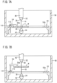
- FIGS. 7A and 7B are schematic sectional views of the interior of a work-pan 50.
- FIG. 7A is a diagram showing a state in which the workpiece W is being machined.
- FIG. 7B is a diagram showing a state in which the workpiece W has been moved in the Z-axis direction by the lifting mechanism 110.
- the lifting mechanism 110 has an unillustrated lift motor and the like, which is driven to move the retainer 54a of the jig 54 in the Z-axis direction. At this time, the workpiece W fixed by the jig 54 also moves in the Z-axis direction together with the retainer 54a.
- the lifting mechanism 110 has a linear scale 112 for detecting the movement of the retainer 54a.
- the configuration of the controller 16 of the second embodiment is substantially the same as that of the controller 16 of the first embodiment.
- the specific control method of the controller 16 of the second embodiment is the same as the control method of the controller 16 of the first embodiment.
- various pieces of information are input from the drop detection sensor 44, the linear scale 66 and the distance measuring sensor 72, to output command signals for controlling the articulated robot 14, the torque motor 24, the brake motor 28, the X-axis motor 62, the Y-axis motor 58, the Z-axis motor of the Z-axis driving mechanism 40 and the lifting mechanism 64.
- controller 16 of the second embodiment various pieces of information are input from the drop detection sensor 44, the linear scale 112 and the distance measuring sensor 72, to output command signals for controlling the articulated robot 14, the feed mechanism 20 (the torque motor 24, the brake motor 28), the X-axis motor 62, the Y-axis motor 58, the Z-axis motor of the Z-axis driving mechanism 40 and the lifting mechanism 110.
- the jig 54 is provided with the lifting mechanism 110 for moving the workpiece W in the traveling direction (Z-axis direction) of the wire electrode 18. Thereby, a space can be secured between the workpiece W and the lower nozzle 38, so that the core C having dropped in the lower nozzle 38 can be easily collected.
- the lifting mechanism 64 is driven not only to collect the core C, but also at the time of normal machining.
- FIGS. 8A and 8B are schematic sectional views of the interior of the work-pan 50.
- FIG. 8A is a diagram showing a state in which a thin portion Wa of the workpiece W is being machined.
- FIG. 8B is a diagram showing a state in which a thick portion Wb of the workpiece W is being machined. The undersurface of the thick portion Wb protrudes downward or in the negative Z-axis direction compared to the undersurface of the thin portion Wa.
- the lifting mechanism control unit 96 computes a command signal for adjusting the distance between the undersurface of the workpiece W and the lower nozzle 38 at a predetermined distance and outputs the command signal to the lifting mechanism 64.
- the Z-axis drive control unit 98 computes a command signal for adjusting the distance between the upper surface of the workpiece W and the upper nozzle 36 at a predetermined distance and outputs the command signal to the Z-axis motor of the Z-axis driving mechanism 40.
- the lifting mechanism control unit 96 computes the command signal so that the undersurface of the workpiece W will be spaced the predetermined distance from the lower nozzle 38 at the machining position of the workpiece W moving according to the NC program. Further, the Z-axis drive control unit 98 computes the command signal so that the upper nozzle 36 will be spaced the predetermined distance from the upper surface of the workpiece W at the machining position of the workpiece W moving according to the NC program.
- the distance between the undersurface of the workpiece W and the lower nozzle 38 can be kept at a distance Ha set in advance while the distance between the upper surface of the workpiece W and the upper nozzle 36 can be kept at a predetermined distance Hb, whereby it is possible to improve the machining accuracy of the workpiece W.
- the lifting mechanism control unit 96 controls the lifting mechanism 64 so as to keep the undersurface of the workpiece W from the lower nozzle 38 at the predetermined distance at the machining point of the workpiece W moving according to the NC program.
- the distance between the undersurface of the workpiece W and the lower nozzle 38 can always be maintained at a predetermined distance during the machining of the workpiece W, whereby it is possible to improve the machining accuracy of the workpiece W.
- the drop detection sensor 44 detects a fall of the core C into the lower nozzle 38 from the decrease or fluctuation of the current between the wire electrode 18 and the workpiece W.
- the drop detection sensor 44 may be configured to detect a fall of the core C into the lower nozzle 38 based on the torque of the X-axis motor 62 and the torque of the Y-axis motor 58. As shown in FIG. 5 , when the dropped core C is located straddling between the workpiece W and the lower nozzle 38, greater torque than usual acts on the X-axis motor 62 and the Y-axis motor 58. That is, the drop detection sensor 44 can detect a fall of the core C into the lower nozzle 38 from the fact that the torque of the X-axis motor 62 and the torque of the Y-axis motor 58 become greater than the predetermined torque.
- the lifting mechanism 64 or 110 moves the workpiece W upward to the upper nozzle 36 when the core C falls into the lower nozzle 38.
- the lifting mechanisms 64, 110 may be configured to move the workpiece W upward to the upper nozzle 36 when the core C just interferes with the edge of the lower nozzle 38, instead of falling into the lower nozzle 38.
- the lifting mechanism 64 of the work table 52 of the first embodiment is also used to adjust the distance between the undersurface of the workpiece W and the lower nozzle 38 to the predetermined distance during the machining of the workpiece W.
- the lifting mechanism 110 of the jig 54 of the second embodiment may also be used to keep the distance between the undersurface of the workpiece W and the lower nozzle 38 at the predetermined distance during the machining of the workpiece W.
Landscapes
- Engineering & Computer Science (AREA)
- Mechanical Engineering (AREA)
- Chemical & Material Sciences (AREA)
- Chemical Kinetics & Catalysis (AREA)
- Electrochemistry (AREA)
- Automation & Control Theory (AREA)
- Electrical Discharge Machining, Electrochemical Machining, And Combined Machining (AREA)
Claims (9)
- Eine Drahterosionsmaschine (12) zum Durchführen einer elektrischen Entladungsbearbeitung an einem Werkstück (W) durch Anlegen einer Spannung über einen Elektrodenspalt zwischen einer Drahtelektrode (18), die zwischen einer oberen Düse (36) und einer unteren Düse (38) und dem Werkstück (W) gespannt ist, um elektrische Entladungen zu erzeugen, umfassend:einen Hebemechanismus (64, 110), der so konfiguriert ist, dass er das Werkstück (W) in einer Bewegungsrichtung der Drahtelektrode (18) bewegt, undein Steuergerät (16) mit einer Speichereinheit (80) und einer Verarbeitungseinheit (82),dadurch gekennzeichnet, dass die Verarbeitungseinheit (82) umfasst:eine Hebemechanismus-Steuereinheit (96), die zur Steuerung des Hebemechanismus (64, 110) konfiguriert ist, undeine Tropfeninformationserfassungseinheit (44), die so konfiguriert ist, dass sie Informationen erfasst, die anzeigen, dass ein Kern (C), der bei der Bearbeitung des Werkstücks (W) gebildet wurde, in die untere Düse (38) gefallen ist oder mit einem Rand der unteren Düse (38) kollidiert ist, wobei die Hebemechanismus-Steuereinheit (96) so konfiguriert ist, dass sie den Hebemechanismus (64, 110) so zu steuern, dass das Werkstück (W) in Richtung der oberen Düse (36) in einem Fall bewegt wird, in dem die Information, dass der Kern (C) in die untere Düse (38) gefallen ist oder mit dem Rand der unteren Düse (38) kollidiert ist, von der Tropfeninformations-Erfassungseinheit (44) erfasst wird.
- Die Drahterosionsmaschine (12) nach Anspruch 1, die ferner einen Arbeitstisch (52) umfasst, auf den das Werkstück (W) gelegt wird, wobei der Hebemechanismus (64) mit dem Arbeitstisch (52) versehen ist und so konfiguriert ist, dass er den Arbeitstisch (52) in der Bewegungsrichtung der Drahtelektrode (18) bewegt.
- Die Drahterosionsmaschine (12) nach Anspruch 1, ferner umfassend:einen Arbeitstisch (52), auf den das Werkstück (W) gelegt wird; undeine Spannvorrichtung (54) zum Befestigen des Werkstücks (W) an dem Arbeitstisch (52), wobei der Hebemechanismus (110) mit der Spannvorrichtung (54) versehen und so konfiguriert ist, dass er die Spannvorrichtung (54) in der Bewegungsrichtung der Drahtelektrode (18) bewegt.
- Die Drahterosionsmaschine (12) nach einem der Ansprüche 1 bis 3, ferner umfassend:eine Blechdicken-Erfassungseinheit (72), die so konfiguriert ist, dass sie Informationen erfasst, die mit der Blechdicke des Werkstücks (W) korreliert sind; undeinen Zielbewegungsrechner (94), der so konfiguriert ist, dass er einen Bewegungsbetrag zum Bewegen des Werkstücks (W) in Richtung der oberen Düse (36) durch den Hebemechanismus (64, 110) aus den Informationen berechnet, die mit der Plattendicke des Werkstücks (W) korreliert sind, wobei die Hebemechanismus-Steuereinheit (96) so konfiguriert ist, dass sie den Hebemechanismus (64, 110) so steuert, dass das Werkstück (W) in Richtung der oberen Düse (36) bewegt wird, basierend auf der berechneten Zielbewegung.
- Die Drahterosionsmaschine (12) nach Anspruch 4, die ferner eine Alarmsteuerung (102) umfasst, die so konfiguriert ist, dass sie auf der Grundlage der berechneten Zielbewegung bestimmt, ob das Werkstück (W) mit der oberen Düse (36) in Konflikt kommt oder nicht, und eine Alarmeinheit (68) steuert, um den Bediener auf den Konflikt des Werkstücks (W) mit der oberen Düse (36) hinzuweisen, wenn das Werkstück (W) mit der oberen Düse (36) in Konflikt kommt.
- Die Drahterosionsmaschine (12) nach einem der Ansprüche 1 bis 5, ferner umfassend:einen oberen Düsenantriebsmechanismus (40), der so konfiguriert ist, dass er die obere Düse (36) in der Bewegungsrichtung der Drahtelektrode (18) bewegt; undeine Oberdüsenantriebssteuereinheit (98), die so konfiguriert ist, dass sie den Oberdüsenantriebsmechanismus (40) so steuert, dass die Oberdüse (36) in der gleichen Richtung wie die Bewegungsrichtung des Werkstücks (W) bewegt wird, wenn das Werkstück (W) durch den Hebemechanismus (64, 110) zur Oberdüse (36) bewegt wird.
- Die Drahterosionsmaschine (12) nach einem der Ansprüche 1 bis 6, wobei die Hebemechanismus-Steuereinheit (96) so konfiguriert ist, dass sie den Hebemechanismus (64, 110) so steuert, dass der Abstand zwischen der unteren Düse (38) und dem Werkstück (W) auf einem vorbestimmten, im Voraus festgelegten Abstand gehalten wird.
- Die Drahterosionsmaschine (12) nach Anspruch 7, ferner umfassend:einen Arbeitstisch (52), auf den das Werkstück (W) gelegt wird;einen Arbeitstisch-Antriebsmechanismus (58, 62), der so konfiguriert ist, dass er den Arbeitstisch (52) und die Drahtelektrode (18) relativ bewegt; undeine Arbeitstisch-Antriebssteuereinheit (86), die so konfiguriert ist, dass sie den Arbeitstisch-Antriebsmechanismus (58, 62) in Übereinstimmung mit einer durch ein voreingestelltes numerisches Steuerprogramm spezifizierten Bearbeitungsform des Werkstücks (W) steuert.
- Ein Drahtelektroerosionsbearbeitungssystem (10), umfassend:eine Drahterosionsmaschine nach einem der Ansprüche 1 bis 8;einen Kernsammelmechanismus (14), der zum Sammeln des in die untere Düse (38) gefallenen Kerns (C) konfiguriert ist; undeine Kernsammelmechanismus-Steuereinheit (100), die so konfiguriert ist, dass sie den Kernsammelmechanismus (14) steuert, um den Kern (C) nach dem Anheben eines Werkstücks (W) mittels des Hebemechanismus (64, 110) zu sammeln.
Applications Claiming Priority (1)
| Application Number | Priority Date | Filing Date | Title |
|---|---|---|---|
| JP2017089633A JP6542832B2 (ja) | 2017-04-28 | 2017-04-28 | ワイヤ放電加工機、ワイヤ放電加工システムおよび治具 |
Publications (2)
| Publication Number | Publication Date |
|---|---|
| EP3395486A1 EP3395486A1 (de) | 2018-10-31 |
| EP3395486B1 true EP3395486B1 (de) | 2024-04-24 |
Family
ID=62067477
Family Applications (1)
| Application Number | Title | Priority Date | Filing Date |
|---|---|---|---|
| EP18169482.9A Active EP3395486B1 (de) | 2017-04-28 | 2018-04-26 | Funkenerosionsmaschine und funkenerosionsbearbeitungssystem |
Country Status (6)
| Country | Link |
|---|---|
| US (1) | US10632554B2 (de) |
| EP (1) | EP3395486B1 (de) |
| JP (1) | JP6542832B2 (de) |
| KR (1) | KR102078001B1 (de) |
| CN (1) | CN108788347B (de) |
| TW (1) | TWI680820B (de) |
Families Citing this family (3)
| Publication number | Priority date | Publication date | Assignee | Title |
|---|---|---|---|---|
| BE1025016B1 (fr) * | 2017-03-02 | 2018-10-03 | Safran Aero Boosters S.A. | Machine et procede d’usinage par electroerosion de pompe gerotor |
| JP7173921B2 (ja) * | 2019-05-10 | 2022-11-16 | ファナック株式会社 | ワイヤ放電加工機およびワイヤ放電加工方法 |
| CN111331584B (zh) * | 2020-03-27 | 2021-10-22 | 厦门理工学院 | 一种复杂曲面加工的机器人系统 |
Family Cites Families (28)
| Publication number | Priority date | Publication date | Assignee | Title |
|---|---|---|---|---|
| JPS6076917A (ja) * | 1983-10-04 | 1985-05-01 | Inoue Japax Res Inc | ワイヤカツト放電加工装置 |
| JPH0622764B2 (ja) * | 1984-06-22 | 1994-03-30 | 株式会社井上ジャパックス研究所 | 切抜部自動取り外し等の作業を行なうロボット装置を備えたワイヤカット放電加工装置 |
| DE3509418A1 (de) * | 1985-03-15 | 1986-09-18 | Aktiengesellschaft für industrielle Elektronik AGIE Losone bei Locarno, Losone, Locarno | Vorrichtung zur sicherung von ausfallstuecken an einer elektroerosionsmaschine |
| JPS61260927A (ja) * | 1985-05-15 | 1986-11-19 | Mitsubishi Electric Corp | ワイヤ放電加工装置 |
| JPS62218025A (ja) * | 1986-03-18 | 1987-09-25 | Honda Motor Co Ltd | 放電加工装置 |
| JPS62264826A (ja) | 1986-05-09 | 1987-11-17 | Seibu Electric & Mach Co Ltd | ワイヤ放電加工機 |
| JPS62264825A (ja) | 1986-05-09 | 1987-11-17 | Mitsubishi Electric Corp | ワイヤ放電加工装置 |
| JPS6311226A (ja) * | 1986-06-30 | 1988-01-18 | Amada Co Ltd | ワイヤカツト放電加工機 |
| JPS6416221U (de) * | 1987-07-21 | 1989-01-26 | ||
| JPH01109026A (ja) | 1987-10-21 | 1989-04-26 | Mitsubishi Electric Corp | ワイヤ放電加工装置 |
| JPH02262916A (ja) * | 1989-03-31 | 1990-10-25 | Mitsubishi Electric Corp | ワイヤ放電加工装置の中子保持装置 |
| JPH03196919A (ja) | 1989-12-26 | 1991-08-28 | Fanuc Ltd | 中子除去方法 |
| JP2586956B2 (ja) * | 1990-03-07 | 1997-03-05 | ファナック株式会社 | 中子除去方法 |
| US5183986A (en) * | 1990-10-08 | 1993-02-02 | Mitsubishi Denki K.K. | Wire-type electric discharge machining system capable magnetically of collecting material that has been removed from a workpiece and confirming the magnetic attraction |
| JPH04146024A (ja) * | 1990-10-09 | 1992-05-20 | Hitachi Seiko Ltd | ワイヤ放電加工機 |
| JPH04310316A (ja) * | 1991-04-09 | 1992-11-02 | Sodick Co Ltd | ワイヤカット放電加工装置 |
| JPH06226541A (ja) * | 1993-01-29 | 1994-08-16 | Canon Inc | ワイヤーカット式の放電加工装置 |
| JPH0819918A (ja) * | 1994-07-07 | 1996-01-23 | Mitsubishi Electric Corp | ワイヤ放電加工方法及びその装置 |
| DE19517548C1 (de) | 1995-05-12 | 1996-10-02 | Vollmer Werke Maschf | Einrichtung zum funkenerosiven Bearbeiten von Werkstücken |
| DE19917104A1 (de) * | 1999-04-15 | 2000-10-26 | System 3R International Ab Vae | Halter zum exakten Positionieren eines Werkstückes |
| JP4127453B2 (ja) * | 2000-06-16 | 2008-07-30 | 三菱電機株式会社 | ワイヤ放電加工機 |
| JP5651091B2 (ja) * | 2011-01-28 | 2015-01-07 | 西部電機株式会社 | ワイヤ放電加工における工作物切り残し加工方法 |
| JP6169635B2 (ja) * | 2015-03-12 | 2017-07-26 | ファナック株式会社 | 加工品(中子)の回収機能を有するワイヤ放電加工機 |
| JP3198290U (ja) | 2015-04-14 | 2015-06-25 | 菱電工機エンジニアリング株式会社 | ワイヤ放電加工用治具 |
| JP6247260B2 (ja) * | 2015-08-24 | 2017-12-13 | ファナック株式会社 | 様々な面の加工が可能なワイヤ放電加工機 |
| JP6363589B2 (ja) * | 2015-12-24 | 2018-07-25 | ファナック株式会社 | ロボットを備えたワイヤ放電加工システム |
| JP6464115B2 (ja) * | 2016-05-25 | 2019-02-06 | ファナック株式会社 | ワイヤ放電加工システム |
| EP3360636B1 (de) * | 2017-02-14 | 2024-06-12 | Agie Charmilles SA | Drahtschneidevorrichtung und verfahren zum trennen von teilen aus einer grundplatte mit einer drahtschneidevorrichtung |
-
2017
- 2017-04-28 JP JP2017089633A patent/JP6542832B2/ja active Active
-
2018
- 2018-04-24 TW TW107113781A patent/TWI680820B/zh active
- 2018-04-24 KR KR1020180047367A patent/KR102078001B1/ko active Active
- 2018-04-26 EP EP18169482.9A patent/EP3395486B1/de active Active
- 2018-04-27 CN CN201810393161.XA patent/CN108788347B/zh active Active
- 2018-04-27 US US15/964,663 patent/US10632554B2/en active Active
Also Published As
| Publication number | Publication date |
|---|---|
| TWI680820B (zh) | 2020-01-01 |
| US10632554B2 (en) | 2020-04-28 |
| KR20180121377A (ko) | 2018-11-07 |
| JP6542832B2 (ja) | 2019-07-10 |
| TW201841705A (zh) | 2018-12-01 |
| CN108788347A (zh) | 2018-11-13 |
| JP2018187693A (ja) | 2018-11-29 |
| CN108788347B (zh) | 2020-02-28 |
| US20180311752A1 (en) | 2018-11-01 |
| KR102078001B1 (ko) | 2020-02-17 |
| EP3395486A1 (de) | 2018-10-31 |
Similar Documents
| Publication | Publication Date | Title |
|---|---|---|
| KR101619917B1 (ko) | 복합 가공 방법 및 복합 가공 장치 | |
| EP3395486B1 (de) | Funkenerosionsmaschine und funkenerosionsbearbeitungssystem | |
| JP6617474B2 (ja) | 数値制御装置と制御方法 | |
| EP3369511B1 (de) | Drahterodiermaschine und steuerungsverfahren für drahterodiermaschine | |
| KR101107544B1 (ko) | 와이어 커트 방전 가공기에 있어서의 마무리 가공 방법 및 와이어 방전 가공기 | |
| US20170087656A1 (en) | Wire electric discharge machine | |
| US11813684B2 (en) | Wire electrical discharge machine and control method | |
| KR101964522B1 (ko) | 와이어 방전 가공기 및 측정 방법 | |
| US11229967B2 (en) | Wire electrical discharge machine and placement time calculation method | |
| US11759906B2 (en) | Machine tool | |
| CN116060710B (zh) | 电极丝放电加工装置以及电极丝放电加工方法 | |
| US11618093B2 (en) | Controlling wire electrical discharge during the machining process | |
| JP4786134B2 (ja) | 切削加工装置 | |
| KR101492636B1 (ko) | 공작기계의 공구 파손 검출 장치 | |
| US20250073798A1 (en) | Control device and control method for controlling wire electrical discharge machine | |
| US20250091146A1 (en) | Control device and control method for controlling wire electrical discharge machine | |
| JPH05337740A (ja) | ワイヤカット放電加工機 |
Legal Events
| Date | Code | Title | Description |
|---|---|---|---|
| PUAI | Public reference made under article 153(3) epc to a published international application that has entered the european phase |
Free format text: ORIGINAL CODE: 0009012 |
|
| STAA | Information on the status of an ep patent application or granted ep patent |
Free format text: STATUS: THE APPLICATION HAS BEEN PUBLISHED |
|
| AK | Designated contracting states |
Kind code of ref document: A1 Designated state(s): AL AT BE BG CH CY CZ DE DK EE ES FI FR GB GR HR HU IE IS IT LI LT LU LV MC MK MT NL NO PL PT RO RS SE SI SK SM TR |
|
| AX | Request for extension of the european patent |
Extension state: BA ME |
|
| STAA | Information on the status of an ep patent application or granted ep patent |
Free format text: STATUS: REQUEST FOR EXAMINATION WAS MADE |
|
| 17P | Request for examination filed |
Effective date: 20190423 |
|
| RBV | Designated contracting states (corrected) |
Designated state(s): AL AT BE BG CH CY CZ DE DK EE ES FI FR GB GR HR HU IE IS IT LI LT LU LV MC MK MT NL NO PL PT RO RS SE SI SK SM TR |
|
| STAA | Information on the status of an ep patent application or granted ep patent |
Free format text: STATUS: EXAMINATION IS IN PROGRESS |
|
| 17Q | First examination report despatched |
Effective date: 20200527 |
|
| RIC1 | Information provided on ipc code assigned before grant |
Ipc: B23H 7/02 20060101ALN20231010BHEP Ipc: B23H 11/00 20060101AFI20231010BHEP |
|
| RIC1 | Information provided on ipc code assigned before grant |
Ipc: B23H 7/02 20060101ALN20231017BHEP Ipc: B23H 11/00 20060101AFI20231017BHEP |
|
| GRAP | Despatch of communication of intention to grant a patent |
Free format text: ORIGINAL CODE: EPIDOSNIGR1 |
|
| STAA | Information on the status of an ep patent application or granted ep patent |
Free format text: STATUS: GRANT OF PATENT IS INTENDED |
|
| RIC1 | Information provided on ipc code assigned before grant |
Ipc: B23H 7/02 20060101ALN20231103BHEP Ipc: B23H 11/00 20060101AFI20231103BHEP |
|
| RIN1 | Information on inventor provided before grant (corrected) |
Inventor name: OOSAWA, TOMOHITO |
|
| INTG | Intention to grant announced |
Effective date: 20231128 |
|
| RIC1 | Information provided on ipc code assigned before grant |
Ipc: B23H 7/02 20060101ALN20231120BHEP Ipc: B23H 11/00 20060101AFI20231120BHEP |
|
| GRAS | Grant fee paid |
Free format text: ORIGINAL CODE: EPIDOSNIGR3 |
|
| GRAA | (expected) grant |
Free format text: ORIGINAL CODE: 0009210 |
|
| STAA | Information on the status of an ep patent application or granted ep patent |
Free format text: STATUS: THE PATENT HAS BEEN GRANTED |
|
| AK | Designated contracting states |
Kind code of ref document: B1 Designated state(s): AL AT BE BG CH CY CZ DE DK EE ES FI FR GB GR HR HU IE IS IT LI LT LU LV MC MK MT NL NO PL PT RO RS SE SI SK SM TR |
|
| REG | Reference to a national code |
Ref country code: GB Ref legal event code: FG4D |
|
| REG | Reference to a national code |
Ref country code: CH Ref legal event code: EP |
|
| REG | Reference to a national code |
Ref country code: DE Ref legal event code: R096 Ref document number: 602018068451 Country of ref document: DE |
|
| REG | Reference to a national code |
Ref country code: IE Ref legal event code: FG4D |
|
| REG | Reference to a national code |
Ref country code: LT Ref legal event code: MG9D |
|
| REG | Reference to a national code |
Ref country code: NL Ref legal event code: MP Effective date: 20240424 |
|
| REG | Reference to a national code |
Ref country code: AT Ref legal event code: MK05 Ref document number: 1679074 Country of ref document: AT Kind code of ref document: T Effective date: 20240424 |
|
| PG25 | Lapsed in a contracting state [announced via postgrant information from national office to epo] |
Ref country code: NL Free format text: LAPSE BECAUSE OF FAILURE TO SUBMIT A TRANSLATION OF THE DESCRIPTION OR TO PAY THE FEE WITHIN THE PRESCRIBED TIME-LIMIT Effective date: 20240424 |
|
| PG25 | Lapsed in a contracting state [announced via postgrant information from national office to epo] |
Ref country code: NL Free format text: LAPSE BECAUSE OF FAILURE TO SUBMIT A TRANSLATION OF THE DESCRIPTION OR TO PAY THE FEE WITHIN THE PRESCRIBED TIME-LIMIT Effective date: 20240424 |
|
| PG25 | Lapsed in a contracting state [announced via postgrant information from national office to epo] |
Ref country code: IS Free format text: LAPSE BECAUSE OF FAILURE TO SUBMIT A TRANSLATION OF THE DESCRIPTION OR TO PAY THE FEE WITHIN THE PRESCRIBED TIME-LIMIT Effective date: 20240824 |
|
| PG25 | Lapsed in a contracting state [announced via postgrant information from national office to epo] |
Ref country code: BG Free format text: LAPSE BECAUSE OF FAILURE TO SUBMIT A TRANSLATION OF THE DESCRIPTION OR TO PAY THE FEE WITHIN THE PRESCRIBED TIME-LIMIT Effective date: 20240424 |
|
| PG25 | Lapsed in a contracting state [announced via postgrant information from national office to epo] |
Ref country code: HR Free format text: LAPSE BECAUSE OF FAILURE TO SUBMIT A TRANSLATION OF THE DESCRIPTION OR TO PAY THE FEE WITHIN THE PRESCRIBED TIME-LIMIT Effective date: 20240424 Ref country code: FI Free format text: LAPSE BECAUSE OF FAILURE TO SUBMIT A TRANSLATION OF THE DESCRIPTION OR TO PAY THE FEE WITHIN THE PRESCRIBED TIME-LIMIT Effective date: 20240424 |
|
| PG25 | Lapsed in a contracting state [announced via postgrant information from national office to epo] |
Ref country code: GR Free format text: LAPSE BECAUSE OF FAILURE TO SUBMIT A TRANSLATION OF THE DESCRIPTION OR TO PAY THE FEE WITHIN THE PRESCRIBED TIME-LIMIT Effective date: 20240725 |
|
| PG25 | Lapsed in a contracting state [announced via postgrant information from national office to epo] |
Ref country code: PT Free format text: LAPSE BECAUSE OF FAILURE TO SUBMIT A TRANSLATION OF THE DESCRIPTION OR TO PAY THE FEE WITHIN THE PRESCRIBED TIME-LIMIT Effective date: 20240826 |
|
| PG25 | Lapsed in a contracting state [announced via postgrant information from national office to epo] |
Ref country code: ES Free format text: LAPSE BECAUSE OF FAILURE TO SUBMIT A TRANSLATION OF THE DESCRIPTION OR TO PAY THE FEE WITHIN THE PRESCRIBED TIME-LIMIT Effective date: 20240424 |
|
| PG25 | Lapsed in a contracting state [announced via postgrant information from national office to epo] |
Ref country code: AT Free format text: LAPSE BECAUSE OF FAILURE TO SUBMIT A TRANSLATION OF THE DESCRIPTION OR TO PAY THE FEE WITHIN THE PRESCRIBED TIME-LIMIT Effective date: 20240424 |
|
| PG25 | Lapsed in a contracting state [announced via postgrant information from national office to epo] |
Ref country code: PL Free format text: LAPSE BECAUSE OF FAILURE TO SUBMIT A TRANSLATION OF THE DESCRIPTION OR TO PAY THE FEE WITHIN THE PRESCRIBED TIME-LIMIT Effective date: 20240424 |
|
| PG25 | Lapsed in a contracting state [announced via postgrant information from national office to epo] |
Ref country code: LV Free format text: LAPSE BECAUSE OF FAILURE TO SUBMIT A TRANSLATION OF THE DESCRIPTION OR TO PAY THE FEE WITHIN THE PRESCRIBED TIME-LIMIT Effective date: 20240424 |
|
| PG25 | Lapsed in a contracting state [announced via postgrant information from national office to epo] |
Ref country code: PT Free format text: LAPSE BECAUSE OF FAILURE TO SUBMIT A TRANSLATION OF THE DESCRIPTION OR TO PAY THE FEE WITHIN THE PRESCRIBED TIME-LIMIT Effective date: 20240826 Ref country code: PL Free format text: LAPSE BECAUSE OF FAILURE TO SUBMIT A TRANSLATION OF THE DESCRIPTION OR TO PAY THE FEE WITHIN THE PRESCRIBED TIME-LIMIT Effective date: 20240424 Ref country code: NO Free format text: LAPSE BECAUSE OF FAILURE TO SUBMIT A TRANSLATION OF THE DESCRIPTION OR TO PAY THE FEE WITHIN THE PRESCRIBED TIME-LIMIT Effective date: 20240724 Ref country code: LV Free format text: LAPSE BECAUSE OF FAILURE TO SUBMIT A TRANSLATION OF THE DESCRIPTION OR TO PAY THE FEE WITHIN THE PRESCRIBED TIME-LIMIT Effective date: 20240424 Ref country code: IS Free format text: LAPSE BECAUSE OF FAILURE TO SUBMIT A TRANSLATION OF THE DESCRIPTION OR TO PAY THE FEE WITHIN THE PRESCRIBED TIME-LIMIT Effective date: 20240824 Ref country code: HR Free format text: LAPSE BECAUSE OF FAILURE TO SUBMIT A TRANSLATION OF THE DESCRIPTION OR TO PAY THE FEE WITHIN THE PRESCRIBED TIME-LIMIT Effective date: 20240424 Ref country code: GR Free format text: LAPSE BECAUSE OF FAILURE TO SUBMIT A TRANSLATION OF THE DESCRIPTION OR TO PAY THE FEE WITHIN THE PRESCRIBED TIME-LIMIT Effective date: 20240725 Ref country code: FI Free format text: LAPSE BECAUSE OF FAILURE TO SUBMIT A TRANSLATION OF THE DESCRIPTION OR TO PAY THE FEE WITHIN THE PRESCRIBED TIME-LIMIT Effective date: 20240424 Ref country code: ES Free format text: LAPSE BECAUSE OF FAILURE TO SUBMIT A TRANSLATION OF THE DESCRIPTION OR TO PAY THE FEE WITHIN THE PRESCRIBED TIME-LIMIT Effective date: 20240424 Ref country code: BG Free format text: LAPSE BECAUSE OF FAILURE TO SUBMIT A TRANSLATION OF THE DESCRIPTION OR TO PAY THE FEE WITHIN THE PRESCRIBED TIME-LIMIT Effective date: 20240424 Ref country code: AT Free format text: LAPSE BECAUSE OF FAILURE TO SUBMIT A TRANSLATION OF THE DESCRIPTION OR TO PAY THE FEE WITHIN THE PRESCRIBED TIME-LIMIT Effective date: 20240424 Ref country code: RS Free format text: LAPSE BECAUSE OF FAILURE TO SUBMIT A TRANSLATION OF THE DESCRIPTION OR TO PAY THE FEE WITHIN THE PRESCRIBED TIME-LIMIT Effective date: 20240724 |
|
| PG25 | Lapsed in a contracting state [announced via postgrant information from national office to epo] |
Ref country code: LU Free format text: LAPSE BECAUSE OF NON-PAYMENT OF DUE FEES Effective date: 20240426 |
|
| REG | Reference to a national code |
Ref country code: BE Ref legal event code: MM Effective date: 20240430 |
|
| PG25 | Lapsed in a contracting state [announced via postgrant information from national office to epo] |
Ref country code: LU Free format text: LAPSE BECAUSE OF NON-PAYMENT OF DUE FEES Effective date: 20240426 |
|
| PG25 | Lapsed in a contracting state [announced via postgrant information from national office to epo] |
Ref country code: DK Free format text: LAPSE BECAUSE OF FAILURE TO SUBMIT A TRANSLATION OF THE DESCRIPTION OR TO PAY THE FEE WITHIN THE PRESCRIBED TIME-LIMIT Effective date: 20240424 |
|
| PG25 | Lapsed in a contracting state [announced via postgrant information from national office to epo] |
Ref country code: BE Free format text: LAPSE BECAUSE OF NON-PAYMENT OF DUE FEES Effective date: 20240430 |
|
| PG25 | Lapsed in a contracting state [announced via postgrant information from national office to epo] |
Ref country code: EE Free format text: LAPSE BECAUSE OF FAILURE TO SUBMIT A TRANSLATION OF THE DESCRIPTION OR TO PAY THE FEE WITHIN THE PRESCRIBED TIME-LIMIT Effective date: 20240424 |
|
| PG25 | Lapsed in a contracting state [announced via postgrant information from national office to epo] |
Ref country code: CZ Free format text: LAPSE BECAUSE OF FAILURE TO SUBMIT A TRANSLATION OF THE DESCRIPTION OR TO PAY THE FEE WITHIN THE PRESCRIBED TIME-LIMIT Effective date: 20240424 |
|
| PG25 | Lapsed in a contracting state [announced via postgrant information from national office to epo] |
Ref country code: SK Free format text: LAPSE BECAUSE OF FAILURE TO SUBMIT A TRANSLATION OF THE DESCRIPTION OR TO PAY THE FEE WITHIN THE PRESCRIBED TIME-LIMIT Effective date: 20240424 Ref country code: RO Free format text: LAPSE BECAUSE OF FAILURE TO SUBMIT A TRANSLATION OF THE DESCRIPTION OR TO PAY THE FEE WITHIN THE PRESCRIBED TIME-LIMIT Effective date: 20240424 |
|
| REG | Reference to a national code |
Ref country code: DE Ref legal event code: R097 Ref document number: 602018068451 Country of ref document: DE |
|
| PG25 | Lapsed in a contracting state [announced via postgrant information from national office to epo] |
Ref country code: SM Free format text: LAPSE BECAUSE OF FAILURE TO SUBMIT A TRANSLATION OF THE DESCRIPTION OR TO PAY THE FEE WITHIN THE PRESCRIBED TIME-LIMIT Effective date: 20240424 |
|
| PG25 | Lapsed in a contracting state [announced via postgrant information from national office to epo] |
Ref country code: SM Free format text: LAPSE BECAUSE OF FAILURE TO SUBMIT A TRANSLATION OF THE DESCRIPTION OR TO PAY THE FEE WITHIN THE PRESCRIBED TIME-LIMIT Effective date: 20240424 Ref country code: SK Free format text: LAPSE BECAUSE OF FAILURE TO SUBMIT A TRANSLATION OF THE DESCRIPTION OR TO PAY THE FEE WITHIN THE PRESCRIBED TIME-LIMIT Effective date: 20240424 Ref country code: RO Free format text: LAPSE BECAUSE OF FAILURE TO SUBMIT A TRANSLATION OF THE DESCRIPTION OR TO PAY THE FEE WITHIN THE PRESCRIBED TIME-LIMIT Effective date: 20240424 Ref country code: EE Free format text: LAPSE BECAUSE OF FAILURE TO SUBMIT A TRANSLATION OF THE DESCRIPTION OR TO PAY THE FEE WITHIN THE PRESCRIBED TIME-LIMIT Effective date: 20240424 Ref country code: DK Free format text: LAPSE BECAUSE OF FAILURE TO SUBMIT A TRANSLATION OF THE DESCRIPTION OR TO PAY THE FEE WITHIN THE PRESCRIBED TIME-LIMIT Effective date: 20240424 Ref country code: CZ Free format text: LAPSE BECAUSE OF FAILURE TO SUBMIT A TRANSLATION OF THE DESCRIPTION OR TO PAY THE FEE WITHIN THE PRESCRIBED TIME-LIMIT Effective date: 20240424 Ref country code: BE Free format text: LAPSE BECAUSE OF NON-PAYMENT OF DUE FEES Effective date: 20240430 Ref country code: MC Free format text: LAPSE BECAUSE OF FAILURE TO SUBMIT A TRANSLATION OF THE DESCRIPTION OR TO PAY THE FEE WITHIN THE PRESCRIBED TIME-LIMIT Effective date: 20240424 |
|
| PLBE | No opposition filed within time limit |
Free format text: ORIGINAL CODE: 0009261 |
|
| STAA | Information on the status of an ep patent application or granted ep patent |
Free format text: STATUS: NO OPPOSITION FILED WITHIN TIME LIMIT |
|
| GBPC | Gb: european patent ceased through non-payment of renewal fee |
Effective date: 20240724 |
|
| 26N | No opposition filed |
Effective date: 20250127 |
|
| PG25 | Lapsed in a contracting state [announced via postgrant information from national office to epo] |
Ref country code: IE Free format text: LAPSE BECAUSE OF NON-PAYMENT OF DUE FEES Effective date: 20240426 |
|
| PG25 | Lapsed in a contracting state [announced via postgrant information from national office to epo] |
Ref country code: SI Free format text: LAPSE BECAUSE OF FAILURE TO SUBMIT A TRANSLATION OF THE DESCRIPTION OR TO PAY THE FEE WITHIN THE PRESCRIBED TIME-LIMIT Effective date: 20240424 |
|
| PG25 | Lapsed in a contracting state [announced via postgrant information from national office to epo] |
Ref country code: FR Free format text: LAPSE BECAUSE OF NON-PAYMENT OF DUE FEES Effective date: 20240624 |
|
| PG25 | Lapsed in a contracting state [announced via postgrant information from national office to epo] |
Ref country code: GB Free format text: LAPSE BECAUSE OF NON-PAYMENT OF DUE FEES Effective date: 20240724 |
|
| PGFP | Annual fee paid to national office [announced via postgrant information from national office to epo] |
Ref country code: DE Payment date: 20250319 Year of fee payment: 8 |
|
| PGFP | Annual fee paid to national office [announced via postgrant information from national office to epo] |
Ref country code: CH Payment date: 20250501 Year of fee payment: 8 |
|
| PG25 | Lapsed in a contracting state [announced via postgrant information from national office to epo] |
Ref country code: CY Free format text: LAPSE BECAUSE OF FAILURE TO SUBMIT A TRANSLATION OF THE DESCRIPTION OR TO PAY THE FEE WITHIN THE PRESCRIBED TIME-LIMIT; INVALID AB INITIO Effective date: 20180426 |
|
| PG25 | Lapsed in a contracting state [announced via postgrant information from national office to epo] |
Ref country code: HU Free format text: LAPSE BECAUSE OF FAILURE TO SUBMIT A TRANSLATION OF THE DESCRIPTION OR TO PAY THE FEE WITHIN THE PRESCRIBED TIME-LIMIT; INVALID AB INITIO Effective date: 20180426 |
|
| PG25 | Lapsed in a contracting state [announced via postgrant information from national office to epo] |
Ref country code: SE Free format text: LAPSE BECAUSE OF FAILURE TO SUBMIT A TRANSLATION OF THE DESCRIPTION OR TO PAY THE FEE WITHIN THE PRESCRIBED TIME-LIMIT Effective date: 20240424 |
|
| PG25 | Lapsed in a contracting state [announced via postgrant information from national office to epo] |
Ref country code: IT Free format text: LAPSE BECAUSE OF FAILURE TO SUBMIT A TRANSLATION OF THE DESCRIPTION OR TO PAY THE FEE WITHIN THE PRESCRIBED TIME-LIMIT Effective date: 20240424 |