EP3390684B1 - Beschichtungsquelle mit strukturierung - Google Patents
Beschichtungsquelle mit strukturierung Download PDFInfo
- Publication number
- EP3390684B1 EP3390684B1 EP16819815.8A EP16819815A EP3390684B1 EP 3390684 B1 EP3390684 B1 EP 3390684B1 EP 16819815 A EP16819815 A EP 16819815A EP 3390684 B1 EP3390684 B1 EP 3390684B1
- Authority
- EP
- European Patent Office
- Prior art keywords
- coating material
- coating
- structuring
- support element
- source
- Prior art date
- Legal status (The legal status is an assumption and is not a legal conclusion. Google has not performed a legal analysis and makes no representation as to the accuracy of the status listed.)
- Active
Links
Images

Classifications
-
- C—CHEMISTRY; METALLURGY
- C23—COATING METALLIC MATERIAL; COATING MATERIAL WITH METALLIC MATERIAL; CHEMICAL SURFACE TREATMENT; DIFFUSION TREATMENT OF METALLIC MATERIAL; COATING BY VACUUM EVAPORATION, BY SPUTTERING, BY ION IMPLANTATION OR BY CHEMICAL VAPOUR DEPOSITION, IN GENERAL; INHIBITING CORROSION OF METALLIC MATERIAL OR INCRUSTATION IN GENERAL
- C23C—COATING METALLIC MATERIAL; COATING MATERIAL WITH METALLIC MATERIAL; SURFACE TREATMENT OF METALLIC MATERIAL BY DIFFUSION INTO THE SURFACE, BY CHEMICAL CONVERSION OR SUBSTITUTION; COATING BY VACUUM EVAPORATION, BY SPUTTERING, BY ION IMPLANTATION OR BY CHEMICAL VAPOUR DEPOSITION, IN GENERAL
- C23C14/00—Coating by vacuum evaporation, by sputtering or by ion implantation of the coating forming material
- C23C14/22—Coating by vacuum evaporation, by sputtering or by ion implantation of the coating forming material characterised by the process of coating
- C23C14/34—Sputtering
- C23C14/3407—Cathode assembly for sputtering apparatus, e.g. Target
-
- C—CHEMISTRY; METALLURGY
- C23—COATING METALLIC MATERIAL; COATING MATERIAL WITH METALLIC MATERIAL; CHEMICAL SURFACE TREATMENT; DIFFUSION TREATMENT OF METALLIC MATERIAL; COATING BY VACUUM EVAPORATION, BY SPUTTERING, BY ION IMPLANTATION OR BY CHEMICAL VAPOUR DEPOSITION, IN GENERAL; INHIBITING CORROSION OF METALLIC MATERIAL OR INCRUSTATION IN GENERAL
- C23C—COATING METALLIC MATERIAL; COATING MATERIAL WITH METALLIC MATERIAL; SURFACE TREATMENT OF METALLIC MATERIAL BY DIFFUSION INTO THE SURFACE, BY CHEMICAL CONVERSION OR SUBSTITUTION; COATING BY VACUUM EVAPORATION, BY SPUTTERING, BY ION IMPLANTATION OR BY CHEMICAL VAPOUR DEPOSITION, IN GENERAL
- C23C14/00—Coating by vacuum evaporation, by sputtering or by ion implantation of the coating forming material
- C23C14/22—Coating by vacuum evaporation, by sputtering or by ion implantation of the coating forming material characterised by the process of coating
- C23C14/24—Vacuum evaporation
-
- C—CHEMISTRY; METALLURGY
- C23—COATING METALLIC MATERIAL; COATING MATERIAL WITH METALLIC MATERIAL; CHEMICAL SURFACE TREATMENT; DIFFUSION TREATMENT OF METALLIC MATERIAL; COATING BY VACUUM EVAPORATION, BY SPUTTERING, BY ION IMPLANTATION OR BY CHEMICAL VAPOUR DEPOSITION, IN GENERAL; INHIBITING CORROSION OF METALLIC MATERIAL OR INCRUSTATION IN GENERAL
- C23C—COATING METALLIC MATERIAL; COATING MATERIAL WITH METALLIC MATERIAL; SURFACE TREATMENT OF METALLIC MATERIAL BY DIFFUSION INTO THE SURFACE, BY CHEMICAL CONVERSION OR SUBSTITUTION; COATING BY VACUUM EVAPORATION, BY SPUTTERING, BY ION IMPLANTATION OR BY CHEMICAL VAPOUR DEPOSITION, IN GENERAL
- C23C14/00—Coating by vacuum evaporation, by sputtering or by ion implantation of the coating forming material
- C23C14/22—Coating by vacuum evaporation, by sputtering or by ion implantation of the coating forming material characterised by the process of coating
- C23C14/34—Sputtering
- C23C14/3407—Cathode assembly for sputtering apparatus, e.g. Target
- C23C14/3414—Metallurgical or chemical aspects of target preparation, e.g. casting, powder metallurgy
-
- C—CHEMISTRY; METALLURGY
- C23—COATING METALLIC MATERIAL; COATING MATERIAL WITH METALLIC MATERIAL; CHEMICAL SURFACE TREATMENT; DIFFUSION TREATMENT OF METALLIC MATERIAL; COATING BY VACUUM EVAPORATION, BY SPUTTERING, BY ION IMPLANTATION OR BY CHEMICAL VAPOUR DEPOSITION, IN GENERAL; INHIBITING CORROSION OF METALLIC MATERIAL OR INCRUSTATION IN GENERAL
- C23C—COATING METALLIC MATERIAL; COATING MATERIAL WITH METALLIC MATERIAL; SURFACE TREATMENT OF METALLIC MATERIAL BY DIFFUSION INTO THE SURFACE, BY CHEMICAL CONVERSION OR SUBSTITUTION; COATING BY VACUUM EVAPORATION, BY SPUTTERING, BY ION IMPLANTATION OR BY CHEMICAL VAPOUR DEPOSITION, IN GENERAL
- C23C14/00—Coating by vacuum evaporation, by sputtering or by ion implantation of the coating forming material
- C23C14/06—Coating by vacuum evaporation, by sputtering or by ion implantation of the coating forming material characterised by the coating material
- C23C14/0635—Carbides
-
- C—CHEMISTRY; METALLURGY
- C23—COATING METALLIC MATERIAL; COATING MATERIAL WITH METALLIC MATERIAL; CHEMICAL SURFACE TREATMENT; DIFFUSION TREATMENT OF METALLIC MATERIAL; COATING BY VACUUM EVAPORATION, BY SPUTTERING, BY ION IMPLANTATION OR BY CHEMICAL VAPOUR DEPOSITION, IN GENERAL; INHIBITING CORROSION OF METALLIC MATERIAL OR INCRUSTATION IN GENERAL
- C23C—COATING METALLIC MATERIAL; COATING MATERIAL WITH METALLIC MATERIAL; SURFACE TREATMENT OF METALLIC MATERIAL BY DIFFUSION INTO THE SURFACE, BY CHEMICAL CONVERSION OR SUBSTITUTION; COATING BY VACUUM EVAPORATION, BY SPUTTERING, BY ION IMPLANTATION OR BY CHEMICAL VAPOUR DEPOSITION, IN GENERAL
- C23C14/00—Coating by vacuum evaporation, by sputtering or by ion implantation of the coating forming material
- C23C14/06—Coating by vacuum evaporation, by sputtering or by ion implantation of the coating forming material characterised by the coating material
- C23C14/067—Borides
-
- H—ELECTRICITY
- H01—ELECTRIC ELEMENTS
- H01J—ELECTRIC DISCHARGE TUBES OR DISCHARGE LAMPS
- H01J37/00—Discharge tubes with provision for introducing objects or material to be exposed to the discharge, e.g. for the purpose of examination or processing thereof
- H01J37/32—Gas-filled discharge tubes
- H01J37/34—Gas-filled discharge tubes operating with cathodic sputtering
- H01J37/3411—Constructional aspects of the reactor
- H01J37/3414—Targets
- H01J37/3426—Material
Definitions
- the invention relates to a coating source for physical vapor deposition and a method for producing a coating source for physical vapor deposition.
- PVD physical vapor deposition
- coating source includes not only, but in a special way, coating sources (often also referred to collectively as a target or sputtering target), as are used in a PVD sputtering process (cathode sputtering) for the deposition of layers on a substrate material provided for this purpose , to understand.
- coating sources often also referred to collectively as a target or sputtering target
- PVD sputtering process cathode sputtering
- coating sources that contain brittle materials or consist of brittle materials represent a great challenge both when using the coating source during the coating process and when producing the coating source itself.
- cooling water is cooled by cooling plates which are arranged on the back of the coating sources. These cooling plates are in turn cooled by the cooling water, which dissipates the heat generated during the coating process.
- Such a support element can also serve as a heat sink, i.e. By applying a support element with a higher thermal conductivity than the coating material, the heat generated in the coating process can be dissipated better. In such a case, the entire arrangement of coating material and support element, which can also serve as a heat sink, is referred to as the coating source.
- Such support elements / heat sinks with high strength and rigidity can be applied to coating materials with low toughness (brittle material behavior) by means of different processes.
- cracks can occur in the coating material or the coating material can break during the coating process.
- the JP62278261 describes a method in which cracks are deliberately introduced into a brittle coating material after a joining step using indium bonds in order to prevent crack formation during the coating process itself. This ensures a more stable coating process.
- the PCT / EP2015 / 001298 describes a method in which cracks are also deliberately introduced into a brittle coating material after a joining step via brazing in order to subsequently enable a more stable sputtering process.
- the cracks arise when cooling from the temperature of the brazing or the crack formation is subsequently supported by a blasting process. In order for this cracking to take place, the expansion coefficient of the support element / heat sink must be lower than that of the coating material.
- the formation of the cracks is random and small pieces of the coating material may flake off.
- the object of the present invention is to provide a coating source which is improved compared to the prior art and a method for producing such a coating source for physical vapor deposition.
- a coating source for physical vapor deposition which has a coating material which consists of a brittle material and has cracks. Furthermore, the coating source has a support element which is connected to the surface of the coating material.
- the coating material of the coating source according to the invention further has a structuring on at least parts of a surface of the coating material.
- a brittle material is understood to mean those materials which have an elongation at break of less than or equal to 1% and thus break near the elastic limit with no or only a small plastic deformation. These materials and therefore the sputtering targets made from them therefore have only a low plastic deformation capacity. Furthermore, brittle materials have a low Toughness, so they show little resistance to crack formation and crack propagation. Examples of such brittle materials are ceramic materials, in particular borides, nitrides, carbides, silicides, oxides but also metallic brittle materials such as Cr or Si or intermetallic compounds such as Ti 3 Al or TiAl 3 and mixtures of these materials.
- the structuring of a coating source according to the invention consists of depressions, grooves, notches or slots which can be introduced in at least parts of a surface of the coating material in various ways.
- the coating material itself can be formed in one or more parts. If the coating material is made up of several parts, the structuring can be introduced into all or only some of the parts of the coating material.
- the shape or the cross section of these depressions, grooves, notches or slots can also be designed differently.
- the cross section can have the shape of a semicircle, a rectangle, a square, a triangle, or a trapezoid.
- the depth of the structuring is preferably between 0.1 and 5 mm.
- the depth of the structuring can also be greater in individual cases, but it must be ensured that at least 1 mm of coating material remains in the depth direction.
- the width of the structuring ie its spatial extent transverse to the direction of the depressions, grooves, notches, slots, etc., is preferably between 0.1 and 2 mm, preferably between 0.1 and 1 mm.
- the cracks preferably run largely along the structuring, which means that the cracks in the structuring or in the vicinity of the structuring run largely parallel to it.
- largely parallel is meant a course of cracks of up to a maximum of 20 °, preferably up to a maximum of 10 ° deviating from the direction of the structuring.
- the spreading of the cracks thus has a clearly recognizable relationship to the structuring, or to the arrangement of the structuring.
- the cracks run in with a predominant part of the total crack length the structuring or largely parallel or with a small inclination angle to it.
- the cracks thus appear in a pattern that largely follows the structuring or the arrangement of the structuring.
- the cracks do not run randomly, but preferentially follow the structuring in their spread.
- the cracks are formed at least largely in a controlled manner and the size of the individual crack-free areas of the coating material (fragments) is at least largely predefined. Small pieces of the coating material can therefore not flake off or only to a small extent. In this way, when using the coating source, it can be ensured that neither the coating system nor the deposited layer is contaminated or damaged by pieces flaking off in this way.
- the cracks preferably run along the structuring with a proportion of the total crack length of more than 50%. This ensures even higher process reliability when using a coating source according to the invention.
- the depth of the cracks preferably extend completely (spatial expansion in the direction of the thickness of the coating source) through the coating material. There is therefore preferably complete material separation between the individual fragments of the coating material.
- the structuring is preferably present on the surface of the coating material facing away from the support element.
- a higher tensile stress is created on the surface of the coating material facing away from the support element than on the surface facing the support element (this is closer to the neutral fiber of the coating source subjected to bending).
- the structuring can be present on the surface of the coating material facing the support element.
- Such an embodiment can offer advantages in the case of particularly brittle coating materials and in the case of special ratios between the thickness of the coating material d 2 and the thickness of the support element d 3 , since the cracks which arise in such cases are particularly fine (small distance between the crack flanks) and in comparison the structure introduced roughly (width of the individual depressions, grooves, notches, etc.) is not visible.
- the structuring can consist of an arrangement of a first group of parallel linear depressions and a second group of parallel linear depressions which are arranged at an angle of 70 ° to 110 ° to the first group of parallel linear depressions.
- Such an arrangement is easy to implement in terms of process technology and the spacing of the respective linear depressions from one another can be easily adapted to the dimensions of the coating source and also to the difference in the thermal expansion coefficients of the coating material and the support element and subsequently the resulting stresses.
- an arrangement at an angle of 70 ° to 110 ° between the groups of the depressions does not result in angles that are too acute and therefore no unfavorable stress concentrations.
- the structuring consists of an arrangement of a first group of parallel linear depressions and a second group of parallel linear depressions which are arranged at right angles to the first group of parallel linear depressions. With such an arrangement, unfavorable stress concentrations are avoided even further.
- the structuring can also exist in other geometrical configurations, for example in the form of concentric circles, which can optionally be overlaid with a star-shaped arrangement of lines.
- a spiral arrangement instead of the concentric circles is also conceivable.
- the coefficient of thermal expansion of the coating material ⁇ 2 is preferably greater than the coefficient of thermal expansion of the support element ⁇ 3 .
- Such a ratio of the thermal expansion coefficients to one another in the production of the coating source which usually includes at least one process step at elevated temperatures, preferably results in the coating material contracting more when cooling from the elevated temperature than the support element and introducing a tensile stress into the coating material which in turn leads to a particularly reliable and reproducible formation of the cracks.
- the greater the difference in the thermal expansion coefficients of the coating material ⁇ 2 and the support element ⁇ 3 the higher the amount of the stresses introduced.
- a coating source according to the invention can have a coating material made of different brittle materials. So it is possible that the coating material made of carbides (e.g.: TiC, SiC, WC), borides (e.g.: TiB 2 , VB 2 , CrB 2 ), nitrides (e.g.: TiN, AIN, TiNAIN), silicides (e.g.: TiSi 2 , CrSi 2 , MoSi 2 ), oxides (e.g.: Al 2 O 3 , (Al, Cr) 2 O 3 ), brittle metals (e.g.: Cr, Si), intermetallic phases (e.g.: Ti 3 Al, TiAl 3 , Al 4 Cr) or mixtures of the above materials.
- the structuring makes it easy to produce a coating source with a coating material made of a brittle material and to operate the coating source even with high line densities.
- a coating source according to the invention preferably has a coating material which consists of TiB 2 , SiC, B 4 C, MoSiB, or CrSiB. It has been found that a structuring can be introduced particularly well in these coating materials and that the cracks run in a particularly uniform manner.
- a coating source according to the invention further preferably has a support element made of molybdenum, tungsten, tantalum, a molybdenum-based alloy, a tungsten-based alloy or a tantalum-based alloy.
- molybdenum-based alloy, tungsten-based alloy or tantalum-based alloy means alloys or composite materials that or contain more than 50 at% molybdenum, tungsten or tantalum.
- Molybdenum, tungsten, tantalum, molybdenum-based alloys, tungsten-based alloys or tantalum-based alloys are particularly suitable for use in a corresponding support element because they have a particularly advantageous combination of properties consisting of a sufficiently high thermal conductivity, a high modulus of elasticity, i.e. high rigidity, and a relatively low level have thermal expansion coefficients.
- the modulus of elasticity of the support element E 3 is greater than or equal to 300 GPa.
- the modulus of elasticity of the support element is even more preferably less than 500 GPa.
- a maximum ratio X of 0.9 is even more preferred.
- a maximum ratio X of 0.85 is even more preferred.
- Coating sources according to the invention can be both plate-shaped and tubular, a targeted introduction of cracks along a structuring is possible for both types of coating sources and has the advantage that the cracks do not run randomly but rather follow the structuring in their spread. Therefore, as described above, small pieces of the coating material, and thus from the coating source, cannot flake off or only to a small extent.
- the coating source is plate-shaped.
- the support element is designed as a back plate.
- the coating source is tubular.
- the support element is designed as a support or support tube.
- Even with a tubular coating source it is particularly advantageous if the thermal expansion coefficient of the coating material ⁇ 2 is greater than the thermal expansion coefficient of the support element (support or support tube) ⁇ 3 .
- a method according to the invention enables the production of a coating source which contains a coating material made of a brittle material and a support element which are connected to one another.
- the coating material is structured and cracks are introduced into the coating material by the method according to the invention.
- Ceramic materials in particular borides, nitrides, carbides, silicides, oxides but also metallic brittle materials such as Cr or Si or intermetallic compounds such as Ti 3 Al or TiAl 3 and mixtures of these materials .
- the structuring of the coating material to produce a structuring can be achieved by various methods.
- the structuring of the coating material is carried out by eroding, wire cutting, grinding or separating cutting.
- at least parts of a surface of the coating material for example, depressions, grooves, notches or Slits introduced that can represent different geometrical arrangements.
- structuring the coating material by pressing in a profiled pressing tool is preferred.
- a pressing of a structuring by means of a profiled pressing tool can take place, for example, during a powder-metallurgical production of the coating material itself.
- the profiled pressing tool can be designed as both an upper and a lower punch in a corresponding pressing device.
- a pre-compacted or pre-compacted blank of a coating material can be structured separately by pressing in a profiled pressing tool.
- the upper or lower punch itself is not profiled, but that a profiled intermediate plate is placed on or under the powder filling or the pre- or pre-compacted blank.
- the structuring can thus produce an arrangement of a first group of parallel linear depressions and a second group of parallel linear depressions which are arranged at an angle of 70 ° to 110 ° to the first group of parallel linear depressions.
- Such an arrangement is easy to implement in terms of process technology and the spacing of the respective linear depressions from one another can be easily adapted to the dimensions of the coating source and also to the difference in the thermal expansion coefficients of the coating material and the support element and subsequently the resulting stresses.
- Such an arrangement is particularly advantageous to produce by eroding, wire cutting, grinding or cutting, but also by pressing a profiled press tool.
- Structuring can further preferably produce an arrangement of a first group of parallel linear depressions and a second group of parallel linear depressions which are arranged at right angles to the first group of parallel linear depressions. With one Unfavorable stress concentrations are avoided even further.
- the structuring can also produce other geometric arrangements, for example a shape of concentric circles, which can optionally be overlaid with a star-shaped arrangement of lines.
- a spiral arrangement instead of the concentric circles is also conceivable. Such an arrangement is particularly advantageous to produce by pressing in a profiled pressing tool.
- the structuring of the coating material is introduced to produce a structuring on at least parts of the surface of the coating material which, after being connected to the support element, is located on the surface of the coating material facing away from the support element.
- the amount of tensile stress on the surface of the coating material facing away from the support element is greater than on the surface facing the support element (this is closer to the neutral fiber).
- the structuring can be carried out on the surface of the coating material facing the support element.
- Such a process step can offer advantages in the case of particularly brittle coating materials and in the case of special ratios between the thickness of the coating material d 2 and the thickness of the support element d 3 , since the cracks which arise in such cases are particularly fine (small distance between the crack flanks) and in comparison the structure introduced roughly (width of the individual depressions, grooves, notches, etc.) is not visible.
- a connection of the coating material to the support element can also be realized in different ways. Preferably finds a connection of the coating material with the support element at temperatures of more than 100 ° C and less than 1000 ° C instead.
- the coating material is connected to the support element by brazing at temperatures between 400 ° C. to 950 ° C.
- brazing in this temperature range, an excellent thermal stability of the coating source can be achieved, which allows the coating source to be operated with particularly high power densities and thus high deposition rates in the coating process.
- the coating chamber is typically heated to temperatures on the order of 400 ° C.
- the coating source is not entirely exposed to these temperatures, since it is additionally cooled from the rear.
- a connection at temperatures between 400 ° C to 950 ° C has the further consequence that the difference in the thermal expansion coefficients of the coating material and the support element results in correspondingly high stresses, preferably tensile stresses, which in turn favor the formation of the cracks.
- the cracks are introduced by cooling from an elevated temperature.
- elevated temperature is understood to mean temperatures of more than 100 ° C. and less than 1000 ° C., which are preferably achieved during the connection of the coating material to the support element.
- connection it is also possible for the connection to be further heated to an elevated temperature, and for the cracks to be introduced when this elevated temperature is cooled.
- the cracks are introduced by cooling from the temperature of the brazing.
- a particularly advantageous temperature gradient arises, which preferably increases the stresses locally Case of tensile stresses in the coating material.
- the notch effect of the structuring also leads to crack formation and crack propagation along the structuring and thus to a deliberately introduced, to a large extent, predefined crack network in the coating material, which preferably runs largely along the structuring.
- a bond via adhesive is particularly suitable for coating sources with very brittle coating materials and, in comparison to the material of the support element, very high coefficients of thermal expansion.
- Radiation of the coating source is preferably carried out after the connection on the surface of the coating material facing away from the support element.
- Abrasive or non-abrasive media can be used as blasting material.
- a blasting of the coating source can support the formation of the cracks, this being caused by the impact of the blasting material (e.g. sandblasting with corundum), which in turn causes the tensions in the coating material to increase further.
- the support for crack formation and crack propagation in the coating material can lead to a reduction in the elastic expansions which have arisen in the support element during the production of the coating source.
- the coating source can be thermally treated, for example by rapid cooling using liquid nitrogen.
- the coating source can be thermally treated, for example by rapid cooling using liquid nitrogen.
- a method according to the invention for producing a coating source is particularly suitable for producing a coating source according to the invention as described above.
- a method according to the invention has proven to be particularly advantageous for the production of coating sources in which the thickness of the coating material has a high thickness in comparison to the support element.
- coating materials that are too thick compared to the support element when the coating source is produced, cause the support element to bend instead of cracking in the coating material. It is believed that in such cases the tensile stresses in the coating material are lower than the breaking stress of the coating material.
- Such deformed (bent) coating sources cannot be properly installed in a coating system. On the other hand, such a deformed coating source would suddenly tear when the critical stress is reached due to the progressive removal during the coating process and the decreasing thickness of the coating material and in turn lead to a disruption of the coating process.
- a maximum ratio X of 0.85 is even more preferred.
- Example 1 (not according to the invention):
- a coating source with a TiB 2 coating material which was connected by brazing to a back plate made of the material MoCu70 / 30wt% was produced.
- the diameter of the coating source was 150 mm and the total thickness d 1 was 12 mm.
- the coating material had a thickness d 2 of 6 mm, the back plate also a thickness d 3 of 6 mm.
- the ratio X d 2 / (d 2 + d 3 ) was therefore 0.5.
- the thermal expansion coefficient of the MoCu70 / 30wt% backplate with 9.5 ppm / K is greater than that of the coating material of 7.3 ppm / K.
- a coating source was prepared with a TiB 2 coating material that was brazed to a thinner Mo backplate.
- the diameter of the coating source was 150 mm and the total thickness d 1 was 16 mm.
- the coating material had a thickness d 2 of 10 mm, the back plate a thickness d 3 of 6 mm.
- the ratio X d 2 / (d 2 + d 3 ) was therefore 0.625.
- the tensile stresses caused by the cooling from the temperature of the brazing were apparently too low, so that it did not lead to the formation of cracks in the coating material came. Instead, the coating material bulged towards the back plate.
- a coating source was made with a CrSiB coating material that was brazed to a Mo backplate.
- the diameter of the coating source was 150 mm and that
- Total thickness d 1 was 12 mm.
- the coating material had a thickness d 2 of 6 mm, the back plate a thickness d 3 of 6 mm.
- the ratio X d 2 / (d 2 + d 3 ) was therefore 0.5.
- the CrSiB coating material is the brittle composition CrSiB 92/3/5 at%. By cooling from the temperature of brazing, cracks have formed perpendicular to the surface of the coating material.
- a coating source was made with a CrSiB coating material that was brazed to a thinner Mo backplate.
- the diameter of the coating source was 100 mm and the total thickness d 1 was 16 mm.
- the coating material had a thickness d 2 of 12 mm, the back plate a thickness d 3 of 4 mm.
- the ratio X d 2 / (d 2 + d 3 ) was therefore 0.75.
- the CrSiB coating material is the brittle composition CrSiB 92/3/5 at%. By cooling from the temperature of brazing, no cracks have arisen.
- a coating source was made with a MoSiB coating material that was brazed to a Mo backplate.
- the diameter of the coating source was 150 mm and the total thickness d 1 was 12 mm.
- the coating material had a thickness d 2 of 6 mm, the back plate a thickness d 3 of 6 mm.
- the ratio X d 2 / (d 2 + d 3 ) was therefore 0.5.
- the MoSiB coating material is the brittle composition MoSiB 50/30/20 at%.
- the coating material was provided with a structure by means of wire cutting before brazing. By cooling from the temperature of brazing, cracks have formed perpendicular to the surface of the coating material. In addition to cracks There are also cracks along the structure, which form an irregular network. There was no flaking of smaller pieces of the coating material.
- a coating source was prepared with a TiB 2 coating material that was brazed to a Mo backplate.
- the diameter of the coating source was 150 mm and the total thickness d 1 was 12 mm.
- the coating material had a thickness d 2 of 6 mm, the back plate a thickness d 3 of 6 mm.
- the ratio X d 2 / (d 2 + d 3 ) was therefore 0.5.
- the coating material was provided with a structure by means of wire cutting before brazing. By cooling from the temperature of brazing, cracks have formed perpendicular to the surface of the coating material. These cracks run largely along the structure. There was no flaking of smaller pieces of the coating material.
- a coating source was prepared with a TiB 2 coating material that was brazed to a Mo backplate.
- the diameter of the coating source was 150 mm and the total thickness d 1 was 12 mm.
- the coating material had a thickness d 2 of 8 mm, the back plate a thickness d 3 of 4 mm.
- the ratio X d 2 / (d 2 + d 3 ) was therefore 0.67.
- the coating material was provided with a structure by means of wire cutting before brazing. This was done using wire cutters with 1 mm deep cuts at right angles to each other. By cooling from the temperature of brazing, cracks have formed perpendicular to the surface of the coating material. These cracks run largely along the structure. There was no flaking of smaller pieces of the coating material.
- a coating source with a TiB 2 coating material which was connected in the form of cylindrical rings by means of brazing to a tubular support element (support or support tube) made of Mo was produced.
- the diameter of the total of 5 TiB 2 rings was 116 mm outside and 91.5 mm inside, the height (extension in the direction of the axis of rotation) of the individual rings was 30 mm.
- the diameter of the Mo support tube was 91.45 mm outside and 76.1 mm inside.
- the total length of the Mo support tube was 200 mm.
- the coating material thus had a thickness of 12.25 mm and the support tube had a thickness of 7.67 mm.
- the ratio X d 2 / (d 2 + d 3 ) was therefore 0.62.
- the coating material was provided with a structure by means of wire cutting before brazing. This was done using wire cutting with parallel and 1 mm deep cuts. By cooling from the temperature of brazing, cracks have formed perpendicular to the surface of the coating material. These cracks run largely along the structure. There was no flaking of smaller pieces of the coating material.
- a crack network can also occur without structuring, and in the case of thicker coating materials the back plate is deformed elastically and / or plastically, or it bends or bulges. Therefore, a crack network was formed in the CrSiB / Mo coating source with 6 mm CrSiB on 6 mm Mo from Example 3, while the TiB 2 / Mo coating source with 10 mm TiB 2 on 6 mm Mo from Example 2 showed no cracks in the TiB 2 and the Mo plate was bent. With a structure like for example in example 7, cracks can be introduced along the structuring, which is probably due to a reduction in the load-bearing cross-section (the thickness) of the coating material or to a notch effect and local stress increase, or a combination thereof.
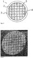
- Figure 1 shows a coating source (1) for physical vapor deposition prior to the introduction of the cracks.
- the coating source (1) has a coating material (2) and a support element (3).
- the coating material (2) is connected to the support element (3) on a surface of the coating material (2).
- the coating material (2) has a structure (5).
- the structuring (5) consists of an arrangement of a first group of parallel linear depressions (shown in dashed lines) and a second group of parallel linear depressions (shown in dashed lines) which are arranged at right angles to the first group of parallel linear depressions.
- Figure 2 shows a top view of the coating source of FIG Figure 1 .
- Figure 3 shows a coating source according to the invention after the introduction of the cracks (4).
- the cracks (4) run largely along the structure (5).
- Figure 4 shows a coating source which was prepared according to Example 5. It has a MoSiB coating material that was applied to a Mo backplate by means of brazing and then cleaned. In addition to cracks along the structure, there are also cracks that form an irregular network. There was no flaking of smaller pieces of the coating material.
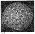
- Figure 5 shows a coating source which was prepared according to Example 6. It has a TiB 2 coating material which was applied to the Mo backplate by means of brazing. The introduced cracks were made visible by means of fluorescent paint through a dye penetration test.
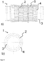
- Figure 6 shows a tubular coating source (1).
- a side view of the tubular coating source (1) is shown
- a top view in the direction of the axis of rotation of the coating source (1) is shown.
- the coating material (2) is made up of individual cylindrical rings
- the support element (3) is designed as a support or carrier tube.
- the structuring (5) is applied to the outer surface of the coating material (2), the cracks (4) run largely along the structuring (5).
Landscapes
- Chemical & Material Sciences (AREA)
- Engineering & Computer Science (AREA)
- Chemical Kinetics & Catalysis (AREA)
- Materials Engineering (AREA)
- Mechanical Engineering (AREA)
- Metallurgy (AREA)
- Organic Chemistry (AREA)
- Physics & Mathematics (AREA)
- Plasma & Fusion (AREA)
- Analytical Chemistry (AREA)
- Physical Vapour Deposition (AREA)
Applications Claiming Priority (2)
| Application Number | Priority Date | Filing Date | Title |
|---|---|---|---|
| ATGM371/2015U AT15050U1 (de) | 2015-12-18 | 2015-12-18 | Beschichtungsquelle mit Strukturierung |
| PCT/EP2016/002059 WO2017102069A1 (de) | 2015-12-18 | 2016-12-07 | Beschichtungsquelle mit strukturierung |
Publications (2)
| Publication Number | Publication Date |
|---|---|
| EP3390684A1 EP3390684A1 (de) | 2018-10-24 |
| EP3390684B1 true EP3390684B1 (de) | 2020-03-18 |
Family
ID=57227207
Family Applications (1)
| Application Number | Title | Priority Date | Filing Date |
|---|---|---|---|
| EP16819815.8A Active EP3390684B1 (de) | 2015-12-18 | 2016-12-07 | Beschichtungsquelle mit strukturierung |
Country Status (8)
| Country | Link |
|---|---|
| US (1) | US20190003036A1 (enExample) |
| EP (1) | EP3390684B1 (enExample) |
| JP (1) | JP7023844B2 (enExample) |
| KR (1) | KR102657632B1 (enExample) |
| CN (1) | CN108391438B (enExample) |
| AT (1) | AT15050U1 (enExample) |
| TW (1) | TWI711710B (enExample) |
| WO (1) | WO2017102069A1 (enExample) |
Families Citing this family (3)
| Publication number | Priority date | Publication date | Assignee | Title |
|---|---|---|---|---|
| DE102020115914B4 (de) | 2020-06-17 | 2024-03-07 | Sindlhauser Materials Gmbh | Flächiges Sputtertarget |
| CN113930744B (zh) * | 2021-09-29 | 2023-12-15 | 西北核技术研究所 | 一种具有高发射阈值的梯度涂层及其制备方法 |
| KR20250086259A (ko) | 2023-12-06 | 2025-06-13 | 이유진 | 책상의 기능이 내재되어 있는 캐리어 |
Family Cites Families (12)
| Publication number | Priority date | Publication date | Assignee | Title |
|---|---|---|---|---|
| JPS61291964A (ja) * | 1985-06-17 | 1986-12-22 | Anelva Corp | スパツタ用樹脂タ−ゲツト |
| JPS62278261A (ja) * | 1986-05-26 | 1987-12-03 | Seiko Epson Corp | スパツタ用タ−ゲツトの製造方法 |
| JPS63216969A (ja) * | 1987-03-05 | 1988-09-09 | Daido Steel Co Ltd | 加工方法 |
| EP0483375B1 (en) * | 1990-05-15 | 1996-03-13 | Kabushiki Kaisha Toshiba | Sputtering target and production thereof |
| JPH05214518A (ja) * | 1992-02-04 | 1993-08-24 | Hitachi Metals Ltd | スパッタリングターゲットとバッキングプレートの接合体の矯正方法およびスパッタリングターゲット材 |
| JPH05230642A (ja) * | 1992-02-21 | 1993-09-07 | Nissin High Voltage Co Ltd | スパッタ・ターゲット |
| JP3460506B2 (ja) * | 1996-11-01 | 2003-10-27 | 三菱マテリアル株式会社 | 高誘電体膜形成用スパッタリングターゲット |
| DE102004020404B4 (de) * | 2004-04-23 | 2007-06-06 | H. C. Starck Gmbh & Co. Kg | Trägerplatte für Sputtertargets, Verfahren zu ihrer Herstellung und Einheit aus Trägerplatte und Sputtertarget |
| EP1851166A2 (en) * | 2005-01-12 | 2007-11-07 | New York University | System and method for processing nanowires with holographic optical tweezers |
| JP5928237B2 (ja) * | 2012-08-08 | 2016-06-01 | 住友金属鉱山株式会社 | Cu−Ga合金スパッタリングターゲット及びその製造方法 |
| CN104711525B (zh) * | 2013-12-13 | 2018-01-26 | 吉坤日矿日石金属株式会社 | 溅射靶及其制造方法 |
| CN106471151B (zh) | 2014-06-27 | 2019-06-18 | 攀时复合材料有限公司 | 溅镀靶 |
-
2015
- 2015-12-18 AT ATGM371/2015U patent/AT15050U1/de unknown
-
2016
- 2016-10-24 TW TW105134281A patent/TWI711710B/zh not_active IP Right Cessation
- 2016-12-07 EP EP16819815.8A patent/EP3390684B1/de active Active
- 2016-12-07 CN CN201680074480.3A patent/CN108391438B/zh active Active
- 2016-12-07 WO PCT/EP2016/002059 patent/WO2017102069A1/de not_active Ceased
- 2016-12-07 KR KR1020187017106A patent/KR102657632B1/ko active Active
- 2016-12-07 JP JP2018531419A patent/JP7023844B2/ja active Active
- 2016-12-07 US US16/061,688 patent/US20190003036A1/en not_active Abandoned
Non-Patent Citations (1)
| Title |
|---|
| None * |
Also Published As
| Publication number | Publication date |
|---|---|
| US20190003036A1 (en) | 2019-01-03 |
| AT15050U1 (de) | 2016-11-15 |
| JP7023844B2 (ja) | 2022-02-22 |
| TWI711710B (zh) | 2020-12-01 |
| KR102657632B1 (ko) | 2024-04-15 |
| WO2017102069A1 (de) | 2017-06-22 |
| TW201736625A (zh) | 2017-10-16 |
| CN108391438A (zh) | 2018-08-10 |
| KR20180094910A (ko) | 2018-08-24 |
| JP2019502024A (ja) | 2019-01-24 |
| CN108391438B (zh) | 2020-04-14 |
| EP3390684A1 (de) | 2018-10-24 |
Similar Documents
| Publication | Publication Date | Title |
|---|---|---|
| DE60214683T2 (de) | Platten aus refraktärem metall mit einheitlicher textur und verfahren zu ihrer herstellung | |
| DE102007001477B3 (de) | Verfahren und Vorrichtung zum Kaltgasspritzen von Partikeln unterschiedlicher Festigkeit und/oder Duktilität | |
| EP3390684B1 (de) | Beschichtungsquelle mit strukturierung | |
| EP3683332B1 (de) | Schneidwerkzeug mit räumlich strukturierter beschichtung | |
| DE2521377A1 (de) | Zerspanwerkzeug und verfahren zu seiner herstellung | |
| DE112006003537B4 (de) | Verfahren zur Herstellung eines Sputtertargetaufbaus | |
| EP3161180B1 (de) | Sputtering target | |
| DE102019200681B4 (de) | Schneidwerkzeug mit amorphem Kohlenstoff und Multilagenbeschichtung und Verfahren zu dessen Herstellung | |
| EP3167095B1 (de) | Target und verfahren zur herstellung eines targets | |
| DE19629456C1 (de) | Werkzeug, insbesondere für die spanende Materialbearbeitung | |
| EP2361322B1 (de) | Vorrichtung und verfahren zum beschichten eines substrats mittels cvd | |
| DE102019101860A1 (de) | Verfahren zum Diffusionsfügen sowie Vorrichtung hierfür | |
| DE102006047742A1 (de) | Verfahren zur Dekontamination mit Trockeneis | |
| DE102012010916A1 (de) | Schweißwerkzeug und Verfahren zur Herstellung desselben | |
| EP2151149A1 (de) | Chip-resistor-substrat | |
| WO2008040819A1 (de) | Verfahren zur dekontamination mit trockeneis | |
| DE102006023398B4 (de) | Kurbelwellen-Hauptlager von Großmotoren und Verfahren zu seiner Herstellung | |
| DE2161453B2 (de) | Verfahren zur Herstellung eines Reibbelages auf Unterlagen, wie Bremsen oder Kupplungen mittels Plasmastrahl | |
| EP3357630B1 (de) | Verfahren und vorrichtung zum reparieren einer beschädigten schaufelspitze einer gepanzerten und mit einer schaufelbeschichtung versehenen turbinenschaufel | |
| DE102008048576A1 (de) | Herstellungsverfahren, Strangpresse und Matrize für ein Strangpress-Hohlprofil sowie Strangpress-Hohlprofil und Wärmetauscher mit einem Strangpress-Hohlprofil | |
| EP1046492A2 (de) | Verbundwerkstoff, insbesondere in Form eines Bleches, und Verfahren zu seiner Herstellung | |
| DE102004031161A1 (de) | Targetanordnung | |
| DE102008056083B4 (de) | Verfahren zum Herstellen einer Heizvorrichtung und Heizvorrichtung | |
| DE102011083413B4 (de) | Verfahren zum Herstellen einer Röntgenanode und Röntgenanode | |
| DE102019206183A1 (de) | Verfahren zur generativen Herstellung einer Baueinheit sowie ein Kraftfahrzeug |
Legal Events
| Date | Code | Title | Description |
|---|---|---|---|
| STAA | Information on the status of an ep patent application or granted ep patent |
Free format text: STATUS: UNKNOWN |
|
| STAA | Information on the status of an ep patent application or granted ep patent |
Free format text: STATUS: THE INTERNATIONAL PUBLICATION HAS BEEN MADE |
|
| PUAI | Public reference made under article 153(3) epc to a published international application that has entered the european phase |
Free format text: ORIGINAL CODE: 0009012 |
|
| STAA | Information on the status of an ep patent application or granted ep patent |
Free format text: STATUS: REQUEST FOR EXAMINATION WAS MADE |
|
| 17P | Request for examination filed |
Effective date: 20180607 |
|
| AK | Designated contracting states |
Kind code of ref document: A1 Designated state(s): AL AT BE BG CH CY CZ DE DK EE ES FI FR GB GR HR HU IE IS IT LI LT LU LV MC MK MT NL NO PL PT RO RS SE SI SK SM TR |
|
| AX | Request for extension of the european patent |
Extension state: BA ME |
|
| DAV | Request for validation of the european patent (deleted) | ||
| DAX | Request for extension of the european patent (deleted) | ||
| GRAP | Despatch of communication of intention to grant a patent |
Free format text: ORIGINAL CODE: EPIDOSNIGR1 |
|
| STAA | Information on the status of an ep patent application or granted ep patent |
Free format text: STATUS: GRANT OF PATENT IS INTENDED |
|
| INTG | Intention to grant announced |
Effective date: 20191122 |
|
| GRAS | Grant fee paid |
Free format text: ORIGINAL CODE: EPIDOSNIGR3 |
|
| GRAA | (expected) grant |
Free format text: ORIGINAL CODE: 0009210 |
|
| STAA | Information on the status of an ep patent application or granted ep patent |
Free format text: STATUS: THE PATENT HAS BEEN GRANTED |
|
| AK | Designated contracting states |
Kind code of ref document: B1 Designated state(s): AL AT BE BG CH CY CZ DE DK EE ES FI FR GB GR HR HU IE IS IT LI LT LU LV MC MK MT NL NO PL PT RO RS SE SI SK SM TR |
|
| REG | Reference to a national code |
Ref country code: GB Ref legal event code: FG4D Free format text: NOT ENGLISH |
|
| REG | Reference to a national code |
Ref country code: DE Ref legal event code: R096 Ref document number: 502016009222 Country of ref document: DE |
|
| REG | Reference to a national code |
Ref country code: AT Ref legal event code: REF Ref document number: 1245993 Country of ref document: AT Kind code of ref document: T Effective date: 20200415 Ref country code: CH Ref legal event code: NV Representative=s name: DENNEMEYER AG, CH Ref country code: IE Ref legal event code: FG4D Free format text: LANGUAGE OF EP DOCUMENT: GERMAN |
|
| REG | Reference to a national code |
Ref country code: NL Ref legal event code: FP |
|
| REG | Reference to a national code |
Ref country code: SE Ref legal event code: TRGR |
|
| PG25 | Lapsed in a contracting state [announced via postgrant information from national office to epo] |
Ref country code: RS Free format text: LAPSE BECAUSE OF FAILURE TO SUBMIT A TRANSLATION OF THE DESCRIPTION OR TO PAY THE FEE WITHIN THE PRESCRIBED TIME-LIMIT Effective date: 20200318 Ref country code: FI Free format text: LAPSE BECAUSE OF FAILURE TO SUBMIT A TRANSLATION OF THE DESCRIPTION OR TO PAY THE FEE WITHIN THE PRESCRIBED TIME-LIMIT Effective date: 20200318 Ref country code: NO Free format text: LAPSE BECAUSE OF FAILURE TO SUBMIT A TRANSLATION OF THE DESCRIPTION OR TO PAY THE FEE WITHIN THE PRESCRIBED TIME-LIMIT Effective date: 20200618 |
|
| PG25 | Lapsed in a contracting state [announced via postgrant information from national office to epo] |
Ref country code: HR Free format text: LAPSE BECAUSE OF FAILURE TO SUBMIT A TRANSLATION OF THE DESCRIPTION OR TO PAY THE FEE WITHIN THE PRESCRIBED TIME-LIMIT Effective date: 20200318 Ref country code: LV Free format text: LAPSE BECAUSE OF FAILURE TO SUBMIT A TRANSLATION OF THE DESCRIPTION OR TO PAY THE FEE WITHIN THE PRESCRIBED TIME-LIMIT Effective date: 20200318 Ref country code: BG Free format text: LAPSE BECAUSE OF FAILURE TO SUBMIT A TRANSLATION OF THE DESCRIPTION OR TO PAY THE FEE WITHIN THE PRESCRIBED TIME-LIMIT Effective date: 20200618 Ref country code: GR Free format text: LAPSE BECAUSE OF FAILURE TO SUBMIT A TRANSLATION OF THE DESCRIPTION OR TO PAY THE FEE WITHIN THE PRESCRIBED TIME-LIMIT Effective date: 20200619 |
|
| REG | Reference to a national code |
Ref country code: LT Ref legal event code: MG4D |
|
| PG25 | Lapsed in a contracting state [announced via postgrant information from national office to epo] |
Ref country code: LT Free format text: LAPSE BECAUSE OF FAILURE TO SUBMIT A TRANSLATION OF THE DESCRIPTION OR TO PAY THE FEE WITHIN THE PRESCRIBED TIME-LIMIT Effective date: 20200318 Ref country code: RO Free format text: LAPSE BECAUSE OF FAILURE TO SUBMIT A TRANSLATION OF THE DESCRIPTION OR TO PAY THE FEE WITHIN THE PRESCRIBED TIME-LIMIT Effective date: 20200318 Ref country code: PT Free format text: LAPSE BECAUSE OF FAILURE TO SUBMIT A TRANSLATION OF THE DESCRIPTION OR TO PAY THE FEE WITHIN THE PRESCRIBED TIME-LIMIT Effective date: 20200812 Ref country code: EE Free format text: LAPSE BECAUSE OF FAILURE TO SUBMIT A TRANSLATION OF THE DESCRIPTION OR TO PAY THE FEE WITHIN THE PRESCRIBED TIME-LIMIT Effective date: 20200318 Ref country code: SM Free format text: LAPSE BECAUSE OF FAILURE TO SUBMIT A TRANSLATION OF THE DESCRIPTION OR TO PAY THE FEE WITHIN THE PRESCRIBED TIME-LIMIT Effective date: 20200318 Ref country code: SK Free format text: LAPSE BECAUSE OF FAILURE TO SUBMIT A TRANSLATION OF THE DESCRIPTION OR TO PAY THE FEE WITHIN THE PRESCRIBED TIME-LIMIT Effective date: 20200318 Ref country code: IS Free format text: LAPSE BECAUSE OF FAILURE TO SUBMIT A TRANSLATION OF THE DESCRIPTION OR TO PAY THE FEE WITHIN THE PRESCRIBED TIME-LIMIT Effective date: 20200718 |
|
| REG | Reference to a national code |
Ref country code: DE Ref legal event code: R097 Ref document number: 502016009222 Country of ref document: DE |
|
| PLBE | No opposition filed within time limit |
Free format text: ORIGINAL CODE: 0009261 |
|
| STAA | Information on the status of an ep patent application or granted ep patent |
Free format text: STATUS: NO OPPOSITION FILED WITHIN TIME LIMIT |
|
| PG25 | Lapsed in a contracting state [announced via postgrant information from national office to epo] |
Ref country code: ES Free format text: LAPSE BECAUSE OF FAILURE TO SUBMIT A TRANSLATION OF THE DESCRIPTION OR TO PAY THE FEE WITHIN THE PRESCRIBED TIME-LIMIT Effective date: 20200318 Ref country code: DK Free format text: LAPSE BECAUSE OF FAILURE TO SUBMIT A TRANSLATION OF THE DESCRIPTION OR TO PAY THE FEE WITHIN THE PRESCRIBED TIME-LIMIT Effective date: 20200318 Ref country code: IT Free format text: LAPSE BECAUSE OF FAILURE TO SUBMIT A TRANSLATION OF THE DESCRIPTION OR TO PAY THE FEE WITHIN THE PRESCRIBED TIME-LIMIT Effective date: 20200318 |
|
| 26N | No opposition filed |
Effective date: 20201221 |
|
| PG25 | Lapsed in a contracting state [announced via postgrant information from national office to epo] |
Ref country code: PL Free format text: LAPSE BECAUSE OF FAILURE TO SUBMIT A TRANSLATION OF THE DESCRIPTION OR TO PAY THE FEE WITHIN THE PRESCRIBED TIME-LIMIT Effective date: 20200318 |
|
| PG25 | Lapsed in a contracting state [announced via postgrant information from national office to epo] |
Ref country code: SI Free format text: LAPSE BECAUSE OF FAILURE TO SUBMIT A TRANSLATION OF THE DESCRIPTION OR TO PAY THE FEE WITHIN THE PRESCRIBED TIME-LIMIT Effective date: 20200318 |
|
| PG25 | Lapsed in a contracting state [announced via postgrant information from national office to epo] |
Ref country code: MC Free format text: LAPSE BECAUSE OF FAILURE TO SUBMIT A TRANSLATION OF THE DESCRIPTION OR TO PAY THE FEE WITHIN THE PRESCRIBED TIME-LIMIT Effective date: 20200318 |
|
| REG | Reference to a national code |
Ref country code: BE Ref legal event code: MM Effective date: 20201231 |
|
| PG25 | Lapsed in a contracting state [announced via postgrant information from national office to epo] |
Ref country code: LU Free format text: LAPSE BECAUSE OF NON-PAYMENT OF DUE FEES Effective date: 20201207 Ref country code: IE Free format text: LAPSE BECAUSE OF NON-PAYMENT OF DUE FEES Effective date: 20201207 |
|
| PG25 | Lapsed in a contracting state [announced via postgrant information from national office to epo] |
Ref country code: TR Free format text: LAPSE BECAUSE OF FAILURE TO SUBMIT A TRANSLATION OF THE DESCRIPTION OR TO PAY THE FEE WITHIN THE PRESCRIBED TIME-LIMIT Effective date: 20200318 Ref country code: MT Free format text: LAPSE BECAUSE OF FAILURE TO SUBMIT A TRANSLATION OF THE DESCRIPTION OR TO PAY THE FEE WITHIN THE PRESCRIBED TIME-LIMIT Effective date: 20200318 Ref country code: CY Free format text: LAPSE BECAUSE OF FAILURE TO SUBMIT A TRANSLATION OF THE DESCRIPTION OR TO PAY THE FEE WITHIN THE PRESCRIBED TIME-LIMIT Effective date: 20200318 |
|
| PG25 | Lapsed in a contracting state [announced via postgrant information from national office to epo] |
Ref country code: MK Free format text: LAPSE BECAUSE OF FAILURE TO SUBMIT A TRANSLATION OF THE DESCRIPTION OR TO PAY THE FEE WITHIN THE PRESCRIBED TIME-LIMIT Effective date: 20200318 Ref country code: AL Free format text: LAPSE BECAUSE OF FAILURE TO SUBMIT A TRANSLATION OF THE DESCRIPTION OR TO PAY THE FEE WITHIN THE PRESCRIBED TIME-LIMIT Effective date: 20200318 |
|
| PG25 | Lapsed in a contracting state [announced via postgrant information from national office to epo] |
Ref country code: BE Free format text: LAPSE BECAUSE OF NON-PAYMENT OF DUE FEES Effective date: 20201231 |
|
| REG | Reference to a national code |
Ref country code: AT Ref legal event code: MM01 Ref document number: 1245993 Country of ref document: AT Kind code of ref document: T Effective date: 20211207 |
|
| PG25 | Lapsed in a contracting state [announced via postgrant information from national office to epo] |
Ref country code: AT Free format text: LAPSE BECAUSE OF NON-PAYMENT OF DUE FEES Effective date: 20211207 |
|
| PGFP | Annual fee paid to national office [announced via postgrant information from national office to epo] |
Ref country code: DE Payment date: 20241210 Year of fee payment: 9 |
|
| PGFP | Annual fee paid to national office [announced via postgrant information from national office to epo] |
Ref country code: NL Payment date: 20241219 Year of fee payment: 9 |
|
| PGFP | Annual fee paid to national office [announced via postgrant information from national office to epo] |
Ref country code: GB Payment date: 20241226 Year of fee payment: 9 |
|
| PGFP | Annual fee paid to national office [announced via postgrant information from national office to epo] |
Ref country code: FR Payment date: 20241224 Year of fee payment: 9 |
|
| PGFP | Annual fee paid to national office [announced via postgrant information from national office to epo] |
Ref country code: CZ Payment date: 20241129 Year of fee payment: 9 |
|
| PGFP | Annual fee paid to national office [announced via postgrant information from national office to epo] |
Ref country code: SE Payment date: 20241219 Year of fee payment: 9 |
|
| PGFP | Annual fee paid to national office [announced via postgrant information from national office to epo] |
Ref country code: CH Payment date: 20250101 Year of fee payment: 9 |