EP3385441B1 - Bügelbrett - Google Patents
Bügelbrett Download PDFInfo
- Publication number
- EP3385441B1 EP3385441B1 EP18161434.8A EP18161434A EP3385441B1 EP 3385441 B1 EP3385441 B1 EP 3385441B1 EP 18161434 A EP18161434 A EP 18161434A EP 3385441 B1 EP3385441 B1 EP 3385441B1
- Authority
- EP
- European Patent Office
- Prior art keywords
- cord
- ironing board
- cover
- groove
- longitudinal
- Prior art date
- Legal status (The legal status is an assumption and is not a legal conclusion. Google has not performed a legal analysis and makes no representation as to the accuracy of the status listed.)
- Active
Links
Images

Classifications
-
- D—TEXTILES; PAPER
- D06—TREATMENT OF TEXTILES OR THE LIKE; LAUNDERING; FLEXIBLE MATERIALS NOT OTHERWISE PROVIDED FOR
- D06F—LAUNDERING, DRYING, IRONING, PRESSING OR FOLDING TEXTILE ARTICLES
- D06F81/00—Ironing boards
- D06F81/14—Means for attaching covers
-
- D—TEXTILES; PAPER
- D06—TREATMENT OF TEXTILES OR THE LIKE; LAUNDERING; FLEXIBLE MATERIALS NOT OTHERWISE PROVIDED FOR
- D06F—LAUNDERING, DRYING, IRONING, PRESSING OR FOLDING TEXTILE ARTICLES
- D06F81/00—Ironing boards
- D06F81/10—Top board elements
-
- D—TEXTILES; PAPER
- D06—TREATMENT OF TEXTILES OR THE LIKE; LAUNDERING; FLEXIBLE MATERIALS NOT OTHERWISE PROVIDED FOR
- D06F—LAUNDERING, DRYING, IRONING, PRESSING OR FOLDING TEXTILE ARTICLES
- D06F83/00—Coverings or pads for ironing or pressing members
Definitions
- the invention relates to an ironing board.
- the invention particularly relates to an ironing board with a laundry support element and a cover, in the edge of a cord or a rope is incorporated.
- the laundry support element has two longitudinal sides extending along its length in a longitudinal direction and two transverse sides extending along its length in a transverse direction extending transversely to the longitudinal direction, the length of the longitudinal sides being greater than the length of the transverse sides.
- the cover generally engages the longitudinal and transverse sides around the laundry support element.
- the relatively small transverse force through the cover leads to a high cable force, which leads to an elongation of the cord and thus to a deflection in the transverse direction. Therefore, on the long sides, the cord can not apply sufficient holding force, and the cover can not be sufficiently biased.
- the cover can not be held tight, slips during ironing and throws wrinkles.
- the invention thus presents the problem of providing an ironing board, in which the reference to the longitudinal sides is held securely against lateral forces.
- At least one of the longitudinal sides or that both longitudinal sides each have a C-groove, in which the cord is arranged, so that the cord is held in the C-groove.
- the cord is held on one side or both sides on the long sides in the C-slots and can not slip on the corresponding side or on both sides.
- the cord can be stably held on the long sides, without disturbing an aesthetic impression of the ironing board negative.
- the cord can also be designed as a rope.
- the C-groove is a C-shaped depression that extends along the long side extends and which has a constriction formed by the formation in C-shape, which constitutes an opening of the C-groove.
- an insertion zone is formed adjacent to the C-groove in each longitudinal side, wherein an opening of the insertion zone is larger than the opening of the C-groove.
- each longitudinal side has a zone for easy insertion of the cord into the C-groove and further a zone in which the cord can be held securely and firmly on the longitudinal sides of the ironing board.
- the insertion zone is preferably formed as a groove more preferably as a U-groove or C-groove, wherein the opening of the insertion zone is formed by the constriction formed by the formation in C-shape or by ends of the U-shape.
- a diameter of the cord is larger than the opening of the C-groove. This prevents the cord from slipping out of the C-groove.
- the opening of the insertion zone is greater than or equal to the diameter of the cord. This ensures easy insertion of the cord into the insertion zone.
- the insertion zone is formed at an end portion of the longitudinal side adjacent to the transverse side.
- the longitudinal sides run parallel to one another and preferably perpendicular or substantially perpendicular to the transverse sides. Between the longitudinal sides and the transverse sides can still be present side sections which are transverse to the longitudinal sides.
- adjacent in the sense of the invention should be understood to mean that the adjacent parts or elements are spaced apart, i. are not arranged directly adjacent to each other or directly adjacent to each other.
- the term "adjacent" in the sense of the invention should be understood to mean that the adjacent parts or elements are in direct contact with each other.
- the C-groove is preferably formed in a central region of the longitudinal side.
- the cover can be raised in this embodiment of the ironing board on the laundry support element, in which the cord is inserted on both sides in the insertion zones formed on the longitudinal sides and then pushed parallel over the laundry support element until the ends of the cover with the ends of the laundry support element match. The cord is then automatically held in the C-grooves of the long sides.
- the longitudinal sides each have two insertion zones, which are formed adjacent to the C-groove. Based on the operating position of the ironing board, each C-groove is formed centrally between the respective two insertion zones.
- the C-groove and the insertion zones are preferably formed on each longitudinal side so as to extend together along the entire length of each longitudinal side.
- the insertion zones can also be designed such that they also extend along the transverse sides and along the extend optional side sections, which are arranged between the longitudinal and transverse sides.
- a lower fabric is arranged between the laundry support element and the cover. More preferably, the lower fabric and the cover are sewn.
- the lower fabric serves as upholstery.
- the lower fabric and the cover are dimensioned and sewn so that they are wrinkle-free in the tensioned state.
- the lower fabric is dimensioned such that it is arranged on the entire expanded metal and at least partially disposed on the longitudinal sides. As a result, the longitudinal sides are also at least partially padded.
- the lower fabric is at least partially disposed on the transverse sides.
- an outer edge of the lower fabric is sewn to the cover.
- the cord is preferably incorporated into the cover by sewing its edge including the cord in the edge.
- the cover may have a seam if the edge of the cover has been sewn together with the lower fabric or have two seams if the cover is sewn to the lower fabric and its edge enclosing the cord has been sewn separately.
- the edge of the cover may have a recess in which the cord is exposed, i. not incorporated in the margin.
- cord portions of the cord can be held by a cord tensioner.
- a cord tensioner is arranged on the cord, which is arranged at or below one of the transverse sides. Based on the operational installation position of the ironing board of the cord tensioner front or rear of the ironing board is arranged. Due to the cord tensioner, the cord can be tensioned, so that the cover is sufficiently biased.
- the cord tensioner is designed as a curry clamp.
- the curry clamp has two rotatable plastic or metal jaws mounted on parallel axes, between which the cord is clamped.
- the jaws are usually eccentrically shaped and are pressed against each other by springs. To reinforce the clamping action, their support surfaces have a serrated profile.
- the laundry support element comprises an expanded metal mesh and two frame parts, which are arranged adjacent to an edge of the expanded metal mesh or below the expanded metal mesh and each form a longitudinal side.
- the frame parts are arranged adjacent to the edge of the expanded metal.
- the frame parts form the longitudinal sides and the transverse sides; being made integral or in several parts could be.
- the frame parts and the expanded metal can be integrally formed or composed of several parts.
- a hinged frame is preferably arranged, which can carry the laundry support element height adjustable.
- the transverse sides also each have a groove in a preferred embodiment. In this case, an uninterrupted groove may be formed in the longitudinal and transverse sides, which is at least partially C-shaped.
- Fig. 1 shows a partial cross-sectional view of the ironing board according to the invention.
- the ironing board 1 has a laundry support element 2.
- On the laundry support element 2 ironing board cover is arranged, which has a lower fabric 6 with an outer edge 61 and a cover 5 with an edge 51. In the edge 51 of the cover 5, a cord 7 is incorporated.
- the laundry support element 2 has an expanded metal mesh 23 for placing laundry items (not shown) and a frame part 24 forming a longitudinal side 21 of the laundry support element 2.
- the expanded mesh 23 and the frame part 24 are connected to each other but can also be integrally formed, which is not shown here.
- the longitudinal side 21 has a C-groove 4, in which the cord 7 is arranged, so that the cord 7 is held in the C-groove 4.
- the opening 41 is smaller than a diameter of the cord. 7
- Fig. 2 shows a cross-sectional view of an ironing board cover of in Fig. 1 shown ironing board.
- the ironing board cover has the cover 5, the lower fabric 6 and the cord 7.
- the lower fabric 6 is sewn to the cover 5 at its outer edge 61.
- the cord 7 is incorporated.
- the edge 51 is sewn to itself so that it surrounds the cord 7.
- the cover 5 may optionally be sewn to the outer edge 61 of the lower fabric 6 by means of a seam 52 and its edge 51 by means of another seam 52, as on the left side of FIG Fig.
- the edge 51 of the cover 5 can be sewn to itself and the outer edge 61 of the lower fabric 6 by means of a seam 52, as on the right side of the Fig. 2 indicated by the dashed line.
- the dimensioning of the layers is taken into account the different stretching behavior of the materials, so that the cover is wrinkle-free in the tensioned state.
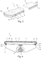
- Fig. 3 shows a partial perspective view of the in Fig. 1 shown ironing board.
- the ironing board 1 is shown without ironing board cover.
- the laundry support element 2 is partially shown, which has the expanded mesh 23 and the frame part 24.
- the frame part 24 is arranged on an edge of the expanded metal grid 23. It surrounds the expanded metal mesh 23 and forms the longitudinal sides 21, one of which is shown extending along its length in a longitudinal direction L, and the two transverse sides 22 extending along its length into a transverse direction, in particular substantially perpendicular to the longitudinal direction L extending transverse direction Q extend.
- the longitudinal side 21 and the transverse side 22 are shown only partially, it can be seen that the length of the longitudinal side 21 is greater than the length of the transverse side 22.
- Each longitudinal side 21 has a C-groove 4 and an insertion zone 3 adjacent to the C-groove 4th on.
- the cord of the ironing board cover can be inserted, and in the C-groove 4, the cord of the ironing board cover can be kept.
- An opening 31 of the insertion zone 3 is larger than the opening 41 of the C-groove 4th
- Fig. 4 shows a further cross-sectional view of the in Fig. 1 shown ironing board.
- Fig. 4 corresponds to Fig.1 with the difference that the entire cross section and not just a partial cross section of the ironing board 1 is shown and that a cord tensioner 8 is shown holding two cord portions 71 of the cord 7.
- the cord tensioner 8 is designed as a curry clamp.
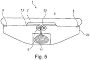
- Fig. 5 shows a plan view of the in Fig. 1 shown ironing board.
- the plan view shows a view of the ironing board 1 on a transverse side, which is covered by the cover 5.
- the cover 5 covers the lower fabric 6 and a sewn in the edge 51 part of the cord 7.
- the edge 51 has a recess 53 in which the cord 7 is exposed.
- the ironing board cover is mounted on the laundry support element 2.
- the cord 7 is inserted through the insertion zones 3 in the C-grooves 4 of the longitudinal sides 21 and then the cover 5 and the lower fabric 6 are pushed in parallel over the expanded mesh 23 of the laundry support member 2 until the ends of the cover 5 with the ends of the expanded mesh 23 match , Subsequently, the cord 7 can be tensioned by means of the cord tensioner 8. Through these steps, the cord 7 is automatically held in the C-grooves 4.
- the ironing board 1 can now be used for ironing.
Landscapes
- Engineering & Computer Science (AREA)
- Textile Engineering (AREA)
- Accessory Of Washing/Drying Machine, Commercial Washing/Drying Machine, Other Washing/Drying Machine (AREA)
Description
- Die Erfindung betrifft ein Bügelbrett. Die Erfindung betrifft insbesondere ein Bügelbrett mit einem Wäscheauflageelement und einem Bezug, in dessen Rand eine Kordel oder ein Seil eingearbeitet ist.
- Gattungsgemäße Bügelbretter sind in der
US 826 748 A ,US 1 182 540 A ,US 1 651 427 A undUS 3 603 011 A offenbart. - Das Wäscheauflageelement weist zwei Längsseiten, die sich entlang ihrer Länge in eine Längsrichtung erstrecken, und zwei Querseiten auf, die sich entlang ihrer Länge in eine sich quer zu der Längsrichtung erstreckenden Querrichtung erstrecken, wobei die Länge der Längsseiten größer ist als die Länge der Querseiten. Der Bezug greift im Allgemeinen an den Längs- und Querseiten um das Wäscheauflageelement. Die relativ kleine Querkraft durch den Bezug führt zu einer hohen Seilkraft, die zu einer Längung der Kordel und damit zu einer Auslenkung in Querrichtung führt. An den Längsseiten kann die Kordel daher keine ausreichende Haltekraft aufbringen, und der Bezug kann nicht ausreichend vorgespannt werden. Der Bezug kann nicht straff gehalten werden, verrutscht während des Bügelns und wirft Falten.
- Der Erfindung stellt sich somit das Problem, ein Bügelbrett bereitzustellen, bei dem der Bezug an den Längsseiten gegen Querkräfte sicher gehalten wird.
- Erfindungsgemäß wird dieses Problem durch ein Bügelbrett mit den Merkmalen des Patentanspruchs 1 gelöst. Vorteilhafte Ausgestaltungen und Weiterbildungen der Erfindung ergeben sich aus den nachfolgenden Unteransprüchen.
- Die mit der Erfindung erreichbaren Vorteile bestehen neben dem Verhindern eines Verrutschens des Bezugs darin, dass der Bezug keine Falten bildet.
- Erfindungsgemäß ist vorgesehen, dass zumindest eine der Längsseiten oder dass beide Längsseiten jeweils eine C-Nut aufweist, in der die Kordel angeordnet ist, sodass die Kordel in der C-Nut gehalten wird. Die Kordel wird dadurch einseitig oder beidseitig an den Längsseiten in den C-Nuten gehalten und kann an der entsprechenden Seite oder an beiden Seiten nicht verrutschen. Zudem kann die Kordel stabil an den Längsseiten gehalten werden, ohne einen ästhetischen Eindruck des Bügelbretts negativ zu stören. Die Kordel kann auch als Seil ausgebildet sein. Die C-Nut ist eine C-förmige Vertiefung, die sich entlang der Längsseite erstreckt und die eine durch die Ausbildung in C-Form ausgebildete Engstelle aufweist, die eine Öffnung der C-Nut darstellt.
- Erfindungsgemäß ist eine Einführzone angrenzend zu der C-Nut in jeder Längsseite ausgebildet, wobei eine Öffnung der Einführzone größer als die Öffnung der C-Nut ist. Dadurch weist jede Längsseite eine Zone zum leichten Einführen der Kordel in die C-Nut und weiterhin eine Zone auf, in der die Kordel sicher und fest an den Längsseiten des Bügelbretts gehalten werden kann. Die Einführzone ist bevorzugt als Nut bevorzugter als eine U-Nut oder C-Nut ausgebildet, wobei die Öffnung der Einführzone durch die durch die Ausbildung in C-Form ausgebildete Engstelle oder durch Enden der U-Form ausgebildet ist.
- Erfindungsgemäß ist ein Durchmesser der Kordel größer als die Öffnung der C-Nut. Dadurch wird ein Herausrutschen der Kordel aus der C-Nut verhindert. Bevorzugt ist die Öffnung der Einführzone größer als der oder gleich zu dem Durchmesser der Kordel. Dadurch wird ein leichtes Einführen der Kordel in die Einführzone sichergestellt.
- Vorzugsweise ist die Einführzone an einem Endbereich der Längsseite ausgebildet, der zu der Querseite benachbart ist. Die Längsseiten verlaufen parallel zueinander und vorzugsweise senkrecht oder im Wesentlichen senkrecht zu den Querseiten. Zwischen den Längsseiten und den Querseiten können weiterhin Seitenabschnitte vorhanden sein, die quer zu den Längsseiten sind. Der Ausdruck "benachbart" ist im Sinne der Erfindung so zu verstehen, dass die benachbarten Teile oder Elemente beabstandet d.h. nicht unmittelbar aneinandergrenzend oder unmittelbar aneinander angrenzend angeordnet sind.
- Der Ausdruck "angrenzend" ist im Sinne der Erfindung so zu verstehen, dass die angrenzenden Teile oder Elemente in unmittelbarem Kontakt zueinander stehen. Die C-Nut ist bevorzugt in einem zentralen Bereich der Längsseite ausgebildet. Der Bezug kann in dieser Ausgestaltung des Bügelbretts auf das Wäscheauflageelement aufgezogen werden, in dem die Kordel beidseitig in die an den Längsseiten ausgebildeten Einführzonen eingeführt wird und dann parallel über das Wäscheauflageelement geschoben wird, bis die Enden des Bezugs mit den Enden des Wäscheauflageelements übereinpassen. Die Kordel wird dann automatisch in den C-Nuten der Längsseiten gehalten.
- Vorzugsweise weisen die Längsseiten jeweils zwei Einführzonen auf, die angrenzend zur C-Nut ausgebildet sind. Bezogen auf die betriebsgemäße Aufstellposition des Bügelbretts, ist jede C-Nut mittig zwischen den jeweiligen zwei Einführzonen ausgebildet. Die C-Nut und die Einführzonen sind vorzugsweise an jeder Längsseite derart ausgebildet, dass sie sich zusammen entlang der gesamten Länge jeder Längsseite erstrecken. Die Einführzonen können weiterhin derart ausgebildet sein, dass sie sich zudem entlang der Querseiten und entlang der optionalen Seitenabschnitte erstrecken, die zwischen den Längs- und Querseiten angeordnet sind.
- Bevorzugt ist zwischen dem Wäscheauflageelement und dem Bezug ein Untergewebe angeordnet. Bevorzugter sind das Untergewebe und der Bezug vernäht. Das Untergewebe dient als Polsterung. Bevorzugt sind das Untergewebe und der Bezug derart dimensioniert und vernäht, dass sie im gespannten Zustand faltenfrei sind. Vorzugsweise ist das Untergewebe derart dimensioniert, dass es auf dem gesamten Streckgitter angeordnet ist und zumindest teilweise an den Längsseiten angeordnet ist. Dadurch sind auch die Längsseiten zumindest teilweise gepolstert. Vorzugsweise ist das Untergewebe zumindest teilweise an den Querseiten angeordnet.
- Bevorzugt ist eine Außenkante des Untergewebes mit dem Bezug vernäht. Die Kordel ist bevorzugt in den Bezug durch Vernähen seines Rands unter Einschluss der Kordel in dem Rand eingearbeitet. Der Bezug kann eine Naht aufweisen, wenn der Rand des Bezugs gleichzeitig mit dem Untergewebe vernäht worden ist, oder zwei Nähte aufweisen, wenn der Bezug mit dem Untergewebe vernäht ist und sein die Kordel einschließender Rand separat vernäht worden ist.
- Der Rand des Bezugs kann eine Aussparung aufweisen, in der die Kordel frei liegt d.h. nicht im Rand eingearbeitet ist. In dieser Aussparung können Kordelabschnitte der Kordel von einem Kordelspanner gehalten werden. In einer bevorzugten Ausführungsform ist an der Kordel ein Kordelspanner angeordnet, der an oder unterhalb einer der Querseiten angeordnet ist. Bezogen auf die betriebsgemäße Aufstellposition des Bügelbretts ist der Kordelspanner vorne oder hinten an dem Bügelbrett angeordnet. Durch den Kordelspanner kann die Kordel gespannt werden, so dass der Bezug ausreichend vorgespannt wird.
- In einer bevorzugten Ausführungsform ist der Kordelspanner als Curryklemme ausgebildet. Die Curryklemme weist zwei drehbare, auf parallelen Achsen angebrachte Kunststoff- oder Metallbacken auf, zwischen denen die Kordel eingeklemmt ist. Die Backen sind üblicherweise exzentrisch geformt und werden durch Federn gegeneinander gepresst. Zur Verstärkung der Klemmwirkung weisen ihre Auflageflächen ein gezacktes Profil auf. Durch die Ausbildung des Kordelspanners als Curryklemme wird sein Festsitzen sichergestellt.
- In einer bevorzugten Ausführungsform weist das Wäscheauflageelement ein Streckgitter und zwei Rahmenteile auf, die angrenzend zu einem Rand des Streckgitters oder unterhalb des Streckgitters angeordnet sind und jeweils eine Längsseite bilden. Bevorzugt sind die Rahmenteile angrenzend zum Rand des Streckgitters angeordnet. Vorzugsweise bilden die Rahmenteile die Längsseiten und die Querseiten; wobei sie integral oder mehrteilig gefertigt sein können. Die Rahmenteile und das Streckgitter können integral ausgebildet oder mehrteilig zusammengesetzt sein. An dem Wäscheauflageelement ist vorzugsweise ein klappbares Gestell angeordnet, das das Wäscheauflageelement höhenverstellbar tragen kann. Die Querseiten weisen in einer bevorzugten Ausführungsform ebenfalls jeweils eine Nut auf. In diesem Fall kann eine ununterbrochene Nut in den Längs- und Querseiten ausgebildet sein, die zumindest teilweise C-förmig ist.
- Ein Ausführungsbeispiel der Erfindung ist in den Zeichnungen rein schematisch dargestellt und wird nachfolgend näher beschrieben. Es zeigt schematisch und nicht maßstabsgerecht
- Fig. 1
- eine Teilquerschnittsansicht des erfindungsgemäßen Bügelbretts;
- Fig. 2
- eine Querschnittsansicht eines Bügelbrettbezugs des in
Fig. 1 gezeigten Bügelbretts; - Fig. 3
- eine perspektivische Teilansicht des in
Fig. 1 gezeigten Bügelbretts; - Fig. 4
- eine Querschnittsansicht des in
Fig. 1 gezeigten Bügelbretts; und - Fig. 5
- eine Draufsicht auf das in
Fig. 1 gezeigte Bügelbrett. -
Fig. 1 zeigt eine Teilquerschnittsansicht des erfindungsgemäßen Bügelbretts. Das Bügelbrett 1 weist eine Wäscheauflageelement 2 auf. Auf der Wäscheauflageelement 2 ist Bügelbrettbezug angeordnet, der ein Untergewebe 6 mit einer Außenkante 61 und einen Bezug 5 mit einem Rand 51 aufweist. In den Rand 51 des Bezugs 5 ist eine Kordel 7 eingearbeitet. Die Wäscheauflageelement 2 weist ein Streckgitter 23 zum Auflegen von Wäschestücken (nicht gezeigt) und ein eine Längsseite 21 des Wäscheauflageelements 2 bildendes Rahmenteil 24 auf. Das Streckgitter 23 und das Rahmenteil 24 sind miteinander verbunden können aber auch einstückig ausgebildet sein, was hier aber nicht gezeigt ist. Die Längsseite 21 weist eine C-Nut 4 auf, in der die Kordel 7 angeordnet ist, sodass die Kordel 7 in der C-Nut 4 gehalten wird. In derFig. 1 befindet sich Kordel 7 in C-Nut 4, deren Öffnung 41 kleiner ist als ein Durchmesser der Kordel 7. -
Fig. 2 zeigt eine Querschnittsansicht eines Bügelbrettbezugs des inFig. 1 gezeigten Bügelbretts. Der Bügelbrettbezug weist den Bezug 5, das Untergewebe 6 und die Kordel 7 auf. Das Untergewebe 6 ist mit dem Bezug 5 an seiner Außenkante 61 vernäht. In den Rand 51 des Bezugs 5 ist die Kordel 7 eingearbeitet. Der Rand 51 ist mit sich selbst vernäht, so dass er die Kordel 7 umgibt. Der Bezug 5 kann wahlweise mit der Außenkante 61 des Untergewebes 6 mittels einer Naht 52 und sein Rand 51 mittels einer weiteren Naht 52 vernäht sein, wie auf der linken Seite derFig. 2 durch die gestrichelten Linien angedeutet, oder alternativ kann der Rand 51 des Bezugs 5 mit sich und der Außenkante 61 des Untergewebes 6 mittels einer Naht 52 vernäht sein, wie auf der rechten Seite derFig. 2 durch die gestrichelte Linie angedeutet. Bei der Dimensionierung der Lagen wird das unterschiedliche Streckverhalten der Materialien berücksichtigt, so dass der Bezug im gespannten Zustand faltenfrei ist. -
Fig. 3 zeigt eine perspektivische Teilansicht des inFig. 1 gezeigten Bügelbretts. Der Übersichtlichkeit halber ist das Bügelbrett 1 ohne Bügelbrettbezug gezeigt. Vielmehr ist das Wäscheauflageelement 2 teilweise gezeigt, das das Streckgitter 23 und das Rahmenteil 24 aufweist. Das Rahmenteil 24 ist an einem Rand des Streckgitters 23 angeordnet. Es umgibt das Streckgitter 23 und bildet die Längsseiten 21, von denen eine gezeigt ist, die sich entlang ihrer Länge in eine Längsrichtung L erstreckt, und die zwei Querseiten 22, die sich entlang ihrer Länge in eine sich quer insbesondere im Wesentlichen senkrecht zu der Längsrichtung L erstreckenden Querrichtung Q erstrecken. Obwohl die Längsseite 21 und die Querseite 22 nur teilweise dargestellt sind, ist ersichtlich, dass die Länge der Längsseite 21 größer ist als die Länge der Querseite 22. Jede Längsseite 21 weist eine C-Nut 4 und eine Einführzone 3 angrenzend zur C-Nut 4 auf. In die Einführzone 3 kann die Kordel des Bügelbrettbezugs eingeführt werden, und in der C-Nut 4 kann die Kordel des Bügelbrettbezugs gehalten werden. Eine Öffnung 31 der Einführzone 3 ist größer als die Öffnung 41 der C-Nut 4. -
Fig. 4 zeigt eine weitere Querschnittsansicht des inFig. 1 gezeigten Bügelbretts.Fig. 4 entsprichtFig.1 , mit dem Unterschied, dass der gesamte Querschnitt und nicht nur ein Teilquerschnitt des Bügelbretts 1 gezeigt ist und dass ein Kordelspanner 8 gezeigt ist, der zwei Kordelabschnitte 71 der Kordel 7 hält. Der Kordelspanner 8 ist als Curryklemme ausgebildet. -
Fig. 5 zeigt eine Draufsicht auf das inFig. 1 gezeigte Bügelbrett. Die Draufsicht zeigt einen Blick auf das Bügelbrett 1 auf eine Querseite, die von dem Bezug 5 bedeckt ist. Der Bezug 5 bedeckt das Untergewebe 6 und einen im Rand 51 eingenähten Teil der Kordel 7. Der Rand 51 weist eine Aussparung 53 auf, in der die Kordel 7 frei liegt. - Zur Herstellung des in
Fig. 1 bis 5 gezeigten Bügelbretts 1 wird der Bügelbrettbezug auf das Wäscheauflageelement 2 aufgezogen. Die Kordel 7 wird durch die Einführzonen 3 in die C-Nuten 4 der Längsseiten 21 eingeführt und dann werden der Bezug 5 und das Untergewebe 6 parallel über das Streckgitter 23 des Wäscheauflageelements 2 geschoben bis die Enden des Bezugs 5 mit den Enden des Streckgitters 23 übereinpassen. Anschließend kann die Kordel 7 mittels des Kordelspanners 8 gespannt werden. Durch diese Schritte wird die Kordel 7 automatisch in den C-Nuten 4 gehalten. Das Bügelbrett 1 kann nun zum Bügeln eingesetzt werden. -
- L
- Längsrichtung
- Q
- Querrichtung
- 1
- Bügelbrett
- 2
- Wäscheauflageelement
- 21
- Längsseite
- 22
- Querseite
- 23
- Streckgitter
- 24
- Rahmenteil
- 3
- Einführzone
- 31
- Öffnung
- 4
- C-Nut
- 41
- Öffnung
- 5
- Bezug
- 51
- Rand
- 52
- Naht
- 53
- Aussparung
- 6
- Untergewebe
- 61
- Außenkante
- 7
- Kordel
- 71
- Kordelabschnitt
- 8
- Kordelspanner
Claims (7)
- Bügelbrett (1) mit einem Wäscheauflageelement (2) und einem das Wäscheauflageelement (2) bedeckende Bezug (5), in dessen Rand (51) eine Kordel (7) eingearbeitet ist, wobei das Wäscheauflageelement (2) zwei Längsseiten (21), die sich entlang ihrer Länge in eine Längsrichtung (L) erstrecken, und zwei Querseiten (22) aufweist, die sich entlang ihrer Länge in eine sich quer zu der Längsrichtung (L) erstreckenden Querrichtung (Q) erstrecken, wobei die Länge der Längsseiten (21) größer ist als die Länge der Querseiten (22), wobei eine der Längsseiten (21) oder jede Längsseite (21) eine C-Nut (4) aufweist, in der die Kordel (7) angeordnet ist, sodass die Kordel (7) in der C-Nut (4) gehalten wird,
dadurch gekennzeichnet,dass eine Einführzone (3) angrenzend zu der C-Nut (4) in der Längsseite (21) ausgebildet ist, wobei eine Öffnung (31) der Einführzone (3) größer ist als eine Öffnung (41) der C-Nut (4), unddass ein Durchmesser der Kordel (7) größer ist als die Öffnung (41) der C-Nut (4). - Bügelbrett (1) nach einem der vorangehenden Ansprüche, dadurch gekennzeichnet, dass die Einführzone (3) an einem Endbereich der Längsseite (21) ausgebildet ist, der zu der Querseite (22) benachbart ist.
- Bügelbrett (1) nach einem der vorangehenden Ansprüche, dadurch gekennzeichnet, dass zwischen dem Wäscheauflageelement (2) und dem Bezug (5) ein Untergewebe (6) angeordnet ist.
- Bügelbrett (1) nach Anspruch 5, dadurch gekennzeichnet, dass das Untergewebe (6) und der Bezug (5) vernäht sind.
- Bügelbrett (1) nach einem der vorangehenden Ansprüche, dadurch gekennzeichnet, dass der Rand (51) des Bezugs (5) eine Aussparung (53) aufweist, in der die Kordel (7) frei liegt.
- Bügelbrett (1) nach einem der vorangehenden Ansprüche, dadurch gekennzeichnet, dass an der Kordel (7) ein Kordelspanner (8) angeordnet ist, der als Curryklemme ausgebildet ist.
- Bügelbrett (1) nach einem der vorangehenden Ansprüchen, dadurch gekennzeichnet, dass das Wäscheauflageelement (2) ein Streckgitter (23) ist und angrenzend zu dessen Rand oder unterhalb des Streckgitters ein die Längsseite (21) bildendes Rahmenteil (24) angeordnet ist.
Applications Claiming Priority (1)
| Application Number | Priority Date | Filing Date | Title |
|---|---|---|---|
| DE102017106735.3A DE102017106735B4 (de) | 2017-03-29 | 2017-03-29 | Bügelbrett |
Publications (2)
| Publication Number | Publication Date |
|---|---|
| EP3385441A1 EP3385441A1 (de) | 2018-10-10 |
| EP3385441B1 true EP3385441B1 (de) | 2019-11-27 |
Family
ID=61628187
Family Applications (1)
| Application Number | Title | Priority Date | Filing Date |
|---|---|---|---|
| EP18161434.8A Active EP3385441B1 (de) | 2017-03-29 | 2018-03-13 | Bügelbrett |
Country Status (2)
| Country | Link |
|---|---|
| EP (1) | EP3385441B1 (de) |
| DE (1) | DE102017106735B4 (de) |
Family Cites Families (9)
| Publication number | Priority date | Publication date | Assignee | Title |
|---|---|---|---|---|
| US826748A (en) * | 1905-04-26 | 1906-07-24 | Reeve Mfg Co | Fastening device for ironing-boards. |
| US1182540A (en) * | 1915-07-16 | 1916-05-09 | Albert Edwards | Ironing-board. |
| US1651427A (en) * | 1926-03-09 | 1927-12-06 | Wegh Edward | Ironing board |
| DE1967724U (de) * | 1967-05-17 | 1967-09-07 | August Schaal K G | Buegelbrett. |
| US3603011A (en) * | 1970-01-12 | 1971-09-07 | Burtest Products Corp | Press pads |
| US6212801B1 (en) * | 1999-09-24 | 2001-04-10 | Bajer Design & Marketing, Inc. | Reversible ironing board cover |
| DE102006054950B3 (de) * | 2006-11-22 | 2008-05-21 | Leifheit Ag | Zusammenklappbares Standgestell für einen Bügeltisch |
| US8267649B2 (en) * | 2009-05-15 | 2012-09-18 | General Electric Company | Coupling for rotary components |
| DE102013216056B4 (de) * | 2013-08-14 | 2016-12-15 | BSH Hausgeräte GmbH | Anordnung für eine Geschirrspülmaschine |
-
2017
- 2017-03-29 DE DE102017106735.3A patent/DE102017106735B4/de not_active Expired - Fee Related
-
2018
- 2018-03-13 EP EP18161434.8A patent/EP3385441B1/de active Active
Non-Patent Citations (1)
| Title |
|---|
| None * |
Also Published As
| Publication number | Publication date |
|---|---|
| EP3385441A1 (de) | 2018-10-10 |
| DE102017106735B4 (de) | 2020-01-23 |
| DE102017106735A1 (de) | 2018-10-04 |
Similar Documents
| Publication | Publication Date | Title |
|---|---|---|
| EP2045047A2 (de) | Gurtanordnung zum Tragen eines handgeführten Arbeitsgeräts | |
| DE102008027248A1 (de) | Wäschebehandlungsmaschine wie Waschmaschine, Wäschetrockner oder dergleichen | |
| EP3385441B1 (de) | Bügelbrett | |
| DE2640935C3 (de) | Vorrichtung zur Befestigung eines Wasser- oder Spülbeckens in einer Tischplatte | |
| DE102009024116B4 (de) | Bezugsabheftung | |
| DE102012215029A1 (de) | Sitzbezugsmaterialbefestigungsstruktur | |
| DE212019000183U1 (de) | Sattelunterlage für ein Pferd | |
| DE2252506A1 (de) | Am rahmen von polstermoebeln anbringbare, aus einem j-foermig gebogenen blechstreifen bestehende klemme zur halterung der enden von zugfedern | |
| DE2616802A1 (de) | Halter fuer lotrecht regelbare fahrzeugsitze | |
| DE202016104234U1 (de) | Höheneinrichtbares Seitenteil für ein Pflegebett | |
| EP0995373A1 (de) | Reihenverbindung für Mehrzweckstühle | |
| DE612772C (de) | Elastische Polsterung fuer Sitz- und Liegemoebel o. dgl. | |
| DE1163169B (de) | Aus einem Sitzbelag und einem an diesen angesetzten elastischen Profilrand bestehendes Sitzkissen fuer Sitzschuesseln, insbesondere fuer Kraftfahrzeuge | |
| DE2706802C3 (de) | Krippe für Stallungen | |
| DE202016103654U1 (de) | Spannhülsensystem und Geländer mit einem Spannhülsensystem | |
| DE10212412A1 (de) | Voltigier- und/oder Longiergurt | |
| DE140625C (de) | ||
| DE102013014057B4 (de) | Einrichtung zur Transportierung eines Aktenordners | |
| AT124125B (de) | Als Hohlkörper ausgestalteter Blechbauteil. | |
| DE1834221U (de) | Vorrichtung zur verbindung von rolladenleisten. | |
| DE2047280A1 (de) | Trager fur Polsterungen | |
| DE1935140A1 (de) | Geraet,das eine Vorrichtung zum Zusammenfassen von Blaettern od.ae. sowie eine Leiste enthaelt,die mit Einrichtungen zum Einklinken in die Vorrichtung zum Zusammenfassen versehen ist | |
| DE20320198U1 (de) | Faltvorrichtung für ein Lauf-Trainingsgerät | |
| DE202004003899U1 (de) | Karabiner mit verriegelbarem Schnapper | |
| EP1875946A2 (de) | Vorrichtung zum Befestigen eines Skifells am hinteren Ende eines Skis |
Legal Events
| Date | Code | Title | Description |
|---|---|---|---|
| PUAI | Public reference made under article 153(3) epc to a published international application that has entered the european phase |
Free format text: ORIGINAL CODE: 0009012 |
|
| STAA | Information on the status of an ep patent application or granted ep patent |
Free format text: STATUS: THE APPLICATION HAS BEEN PUBLISHED |
|
| AK | Designated contracting states |
Kind code of ref document: A1 Designated state(s): AL AT BE BG CH CY CZ DE DK EE ES FI FR GB GR HR HU IE IS IT LI LT LU LV MC MK MT NL NO PL PT RO RS SE SI SK SM TR |
|
| AX | Request for extension of the european patent |
Extension state: BA ME |
|
| STAA | Information on the status of an ep patent application or granted ep patent |
Free format text: STATUS: REQUEST FOR EXAMINATION WAS MADE |
|
| 17P | Request for examination filed |
Effective date: 20190410 |
|
| RBV | Designated contracting states (corrected) |
Designated state(s): AL AT BE BG CH CY CZ DE DK EE ES FI FR GB GR HR HU IE IS IT LI LT LU LV MC MK MT NL NO PL PT RO RS SE SI SK SM TR |
|
| GRAP | Despatch of communication of intention to grant a patent |
Free format text: ORIGINAL CODE: EPIDOSNIGR1 |
|
| STAA | Information on the status of an ep patent application or granted ep patent |
Free format text: STATUS: GRANT OF PATENT IS INTENDED |
|
| RIC1 | Information provided on ipc code assigned before grant |
Ipc: D06F 81/14 20060101AFI20190625BHEP |
|
| INTG | Intention to grant announced |
Effective date: 20190719 |
|
| GRAS | Grant fee paid |
Free format text: ORIGINAL CODE: EPIDOSNIGR3 |
|
| GRAA | (expected) grant |
Free format text: ORIGINAL CODE: 0009210 |
|
| STAA | Information on the status of an ep patent application or granted ep patent |
Free format text: STATUS: THE PATENT HAS BEEN GRANTED |
|
| REG | Reference to a national code |
Ref country code: DE Ref legal event code: R084 Ref document number: 502018000414 Country of ref document: DE |
|
| AK | Designated contracting states |
Kind code of ref document: B1 Designated state(s): AL AT BE BG CH CY CZ DE DK EE ES FI FR GB GR HR HU IE IS IT LI LT LU LV MC MK MT NL NO PL PT RO RS SE SI SK SM TR |
|
| REG | Reference to a national code |
Ref country code: GB Ref legal event code: FG4D Free format text: NOT ENGLISH |
|
| REG | Reference to a national code |
Ref country code: CH Ref legal event code: EP |
|
| REG | Reference to a national code |
Ref country code: CH Ref legal event code: NV Representative=s name: COSMOVICI INTELLECTUAL PROPERTY SARL, CH |
|
| REG | Reference to a national code |
Ref country code: AT Ref legal event code: REF Ref document number: 1206763 Country of ref document: AT Kind code of ref document: T Effective date: 20191215 |
|
| REG | Reference to a national code |
Ref country code: DE Ref legal event code: R096 Ref document number: 502018000414 Country of ref document: DE |
|
| REG | Reference to a national code |
Ref country code: IE Ref legal event code: FG4D Free format text: LANGUAGE OF EP DOCUMENT: GERMAN |
|
| REG | Reference to a national code |
Ref country code: NL Ref legal event code: MP Effective date: 20191127 |
|
| REG | Reference to a national code |
Ref country code: LT Ref legal event code: MG4D |
|
| PG25 | Lapsed in a contracting state [announced via postgrant information from national office to epo] |
Ref country code: NO Free format text: LAPSE BECAUSE OF FAILURE TO SUBMIT A TRANSLATION OF THE DESCRIPTION OR TO PAY THE FEE WITHIN THE PRESCRIBED TIME-LIMIT Effective date: 20200227 Ref country code: GR Free format text: LAPSE BECAUSE OF FAILURE TO SUBMIT A TRANSLATION OF THE DESCRIPTION OR TO PAY THE FEE WITHIN THE PRESCRIBED TIME-LIMIT Effective date: 20200228 Ref country code: LT Free format text: LAPSE BECAUSE OF FAILURE TO SUBMIT A TRANSLATION OF THE DESCRIPTION OR TO PAY THE FEE WITHIN THE PRESCRIBED TIME-LIMIT Effective date: 20191127 Ref country code: SE Free format text: LAPSE BECAUSE OF FAILURE TO SUBMIT A TRANSLATION OF THE DESCRIPTION OR TO PAY THE FEE WITHIN THE PRESCRIBED TIME-LIMIT Effective date: 20191127 Ref country code: LV Free format text: LAPSE BECAUSE OF FAILURE TO SUBMIT A TRANSLATION OF THE DESCRIPTION OR TO PAY THE FEE WITHIN THE PRESCRIBED TIME-LIMIT Effective date: 20191127 Ref country code: NL Free format text: LAPSE BECAUSE OF FAILURE TO SUBMIT A TRANSLATION OF THE DESCRIPTION OR TO PAY THE FEE WITHIN THE PRESCRIBED TIME-LIMIT Effective date: 20191127 Ref country code: FI Free format text: LAPSE BECAUSE OF FAILURE TO SUBMIT A TRANSLATION OF THE DESCRIPTION OR TO PAY THE FEE WITHIN THE PRESCRIBED TIME-LIMIT Effective date: 20191127 Ref country code: BG Free format text: LAPSE BECAUSE OF FAILURE TO SUBMIT A TRANSLATION OF THE DESCRIPTION OR TO PAY THE FEE WITHIN THE PRESCRIBED TIME-LIMIT Effective date: 20200227 |
|
| PG25 | Lapsed in a contracting state [announced via postgrant information from national office to epo] |
Ref country code: HR Free format text: LAPSE BECAUSE OF FAILURE TO SUBMIT A TRANSLATION OF THE DESCRIPTION OR TO PAY THE FEE WITHIN THE PRESCRIBED TIME-LIMIT Effective date: 20191127 Ref country code: RS Free format text: LAPSE BECAUSE OF FAILURE TO SUBMIT A TRANSLATION OF THE DESCRIPTION OR TO PAY THE FEE WITHIN THE PRESCRIBED TIME-LIMIT Effective date: 20191127 Ref country code: IS Free format text: LAPSE BECAUSE OF FAILURE TO SUBMIT A TRANSLATION OF THE DESCRIPTION OR TO PAY THE FEE WITHIN THE PRESCRIBED TIME-LIMIT Effective date: 20200327 |
|
| PG25 | Lapsed in a contracting state [announced via postgrant information from national office to epo] |
Ref country code: AL Free format text: LAPSE BECAUSE OF FAILURE TO SUBMIT A TRANSLATION OF THE DESCRIPTION OR TO PAY THE FEE WITHIN THE PRESCRIBED TIME-LIMIT Effective date: 20191127 |
|
| PG25 | Lapsed in a contracting state [announced via postgrant information from national office to epo] |
Ref country code: DK Free format text: LAPSE BECAUSE OF FAILURE TO SUBMIT A TRANSLATION OF THE DESCRIPTION OR TO PAY THE FEE WITHIN THE PRESCRIBED TIME-LIMIT Effective date: 20191127 Ref country code: EE Free format text: LAPSE BECAUSE OF FAILURE TO SUBMIT A TRANSLATION OF THE DESCRIPTION OR TO PAY THE FEE WITHIN THE PRESCRIBED TIME-LIMIT Effective date: 20191127 Ref country code: PT Free format text: LAPSE BECAUSE OF FAILURE TO SUBMIT A TRANSLATION OF THE DESCRIPTION OR TO PAY THE FEE WITHIN THE PRESCRIBED TIME-LIMIT Effective date: 20200419 Ref country code: CZ Free format text: LAPSE BECAUSE OF FAILURE TO SUBMIT A TRANSLATION OF THE DESCRIPTION OR TO PAY THE FEE WITHIN THE PRESCRIBED TIME-LIMIT Effective date: 20191127 Ref country code: ES Free format text: LAPSE BECAUSE OF FAILURE TO SUBMIT A TRANSLATION OF THE DESCRIPTION OR TO PAY THE FEE WITHIN THE PRESCRIBED TIME-LIMIT Effective date: 20191127 Ref country code: RO Free format text: LAPSE BECAUSE OF FAILURE TO SUBMIT A TRANSLATION OF THE DESCRIPTION OR TO PAY THE FEE WITHIN THE PRESCRIBED TIME-LIMIT Effective date: 20191127 |
|
| REG | Reference to a national code |
Ref country code: DE Ref legal event code: R097 Ref document number: 502018000414 Country of ref document: DE |
|
| PG25 | Lapsed in a contracting state [announced via postgrant information from national office to epo] |
Ref country code: SK Free format text: LAPSE BECAUSE OF FAILURE TO SUBMIT A TRANSLATION OF THE DESCRIPTION OR TO PAY THE FEE WITHIN THE PRESCRIBED TIME-LIMIT Effective date: 20191127 Ref country code: SM Free format text: LAPSE BECAUSE OF FAILURE TO SUBMIT A TRANSLATION OF THE DESCRIPTION OR TO PAY THE FEE WITHIN THE PRESCRIBED TIME-LIMIT Effective date: 20191127 |
|
| PLBE | No opposition filed within time limit |
Free format text: ORIGINAL CODE: 0009261 |
|
| STAA | Information on the status of an ep patent application or granted ep patent |
Free format text: STATUS: NO OPPOSITION FILED WITHIN TIME LIMIT |
|
| PG25 | Lapsed in a contracting state [announced via postgrant information from national office to epo] |
Ref country code: MC Free format text: LAPSE BECAUSE OF FAILURE TO SUBMIT A TRANSLATION OF THE DESCRIPTION OR TO PAY THE FEE WITHIN THE PRESCRIBED TIME-LIMIT Effective date: 20191127 |
|
| 26N | No opposition filed |
Effective date: 20200828 |
|
| PG25 | Lapsed in a contracting state [announced via postgrant information from national office to epo] |
Ref country code: PL Free format text: LAPSE BECAUSE OF FAILURE TO SUBMIT A TRANSLATION OF THE DESCRIPTION OR TO PAY THE FEE WITHIN THE PRESCRIBED TIME-LIMIT Effective date: 20191127 Ref country code: SI Free format text: LAPSE BECAUSE OF FAILURE TO SUBMIT A TRANSLATION OF THE DESCRIPTION OR TO PAY THE FEE WITHIN THE PRESCRIBED TIME-LIMIT Effective date: 20191127 |
|
| PG25 | Lapsed in a contracting state [announced via postgrant information from national office to epo] |
Ref country code: LU Free format text: LAPSE BECAUSE OF NON-PAYMENT OF DUE FEES Effective date: 20200313 |
|
| PG25 | Lapsed in a contracting state [announced via postgrant information from national office to epo] |
Ref country code: IE Free format text: LAPSE BECAUSE OF NON-PAYMENT OF DUE FEES Effective date: 20200313 Ref country code: IT Free format text: LAPSE BECAUSE OF FAILURE TO SUBMIT A TRANSLATION OF THE DESCRIPTION OR TO PAY THE FEE WITHIN THE PRESCRIBED TIME-LIMIT Effective date: 20191127 |
|
| PG25 | Lapsed in a contracting state [announced via postgrant information from national office to epo] |
Ref country code: TR Free format text: LAPSE BECAUSE OF FAILURE TO SUBMIT A TRANSLATION OF THE DESCRIPTION OR TO PAY THE FEE WITHIN THE PRESCRIBED TIME-LIMIT Effective date: 20191127 Ref country code: MT Free format text: LAPSE BECAUSE OF FAILURE TO SUBMIT A TRANSLATION OF THE DESCRIPTION OR TO PAY THE FEE WITHIN THE PRESCRIBED TIME-LIMIT Effective date: 20191127 Ref country code: CY Free format text: LAPSE BECAUSE OF FAILURE TO SUBMIT A TRANSLATION OF THE DESCRIPTION OR TO PAY THE FEE WITHIN THE PRESCRIBED TIME-LIMIT Effective date: 20191127 |
|
| PG25 | Lapsed in a contracting state [announced via postgrant information from national office to epo] |
Ref country code: MK Free format text: LAPSE BECAUSE OF FAILURE TO SUBMIT A TRANSLATION OF THE DESCRIPTION OR TO PAY THE FEE WITHIN THE PRESCRIBED TIME-LIMIT Effective date: 20191127 |
|
| GBPC | Gb: european patent ceased through non-payment of renewal fee |
Effective date: 20220313 |
|
| PG25 | Lapsed in a contracting state [announced via postgrant information from national office to epo] |
Ref country code: GB Free format text: LAPSE BECAUSE OF NON-PAYMENT OF DUE FEES Effective date: 20220313 |
|
| P01 | Opt-out of the competence of the unified patent court (upc) registered |
Effective date: 20230528 |
|
| PGFP | Annual fee paid to national office [announced via postgrant information from national office to epo] |
Ref country code: DE Payment date: 20250331 Year of fee payment: 8 |
|
| PGFP | Annual fee paid to national office [announced via postgrant information from national office to epo] |
Ref country code: BE Payment date: 20250325 Year of fee payment: 8 Ref country code: AT Payment date: 20250318 Year of fee payment: 8 |
|
| PGFP | Annual fee paid to national office [announced via postgrant information from national office to epo] |
Ref country code: FR Payment date: 20250324 Year of fee payment: 8 |
|
| PGFP | Annual fee paid to national office [announced via postgrant information from national office to epo] |
Ref country code: CH Payment date: 20250401 Year of fee payment: 8 |