EP3384070B1 - Method for improving catalytic activity - Google Patents
Method for improving catalytic activity Download PDFInfo
- Publication number
- EP3384070B1 EP3384070B1 EP16869410.7A EP16869410A EP3384070B1 EP 3384070 B1 EP3384070 B1 EP 3384070B1 EP 16869410 A EP16869410 A EP 16869410A EP 3384070 B1 EP3384070 B1 EP 3384070B1
- Authority
- EP
- European Patent Office
- Prior art keywords
- composite
- nickel
- nife
- oer
- metallic
- Prior art date
- Legal status (The legal status is an assumption and is not a legal conclusion. Google has not performed a legal analysis and makes no representation as to the accuracy of the status listed.)
- Active
Links
Images


Classifications
-
- B—PERFORMING OPERATIONS; TRANSPORTING
- B01—PHYSICAL OR CHEMICAL PROCESSES OR APPARATUS IN GENERAL
- B01J—CHEMICAL OR PHYSICAL PROCESSES, e.g. CATALYSIS OR COLLOID CHEMISTRY; THEIR RELEVANT APPARATUS
- B01J37/00—Processes, in general, for preparing catalysts; Processes, in general, for activation of catalysts
- B01J37/16—Reducing
- B01J37/18—Reducing with gases containing free hydrogen
-
- B—PERFORMING OPERATIONS; TRANSPORTING
- B01—PHYSICAL OR CHEMICAL PROCESSES OR APPARATUS IN GENERAL
- B01J—CHEMICAL OR PHYSICAL PROCESSES, e.g. CATALYSIS OR COLLOID CHEMISTRY; THEIR RELEVANT APPARATUS
- B01J23/00—Catalysts comprising metals or metal oxides or hydroxides, not provided for in group B01J21/00
- B01J23/70—Catalysts comprising metals or metal oxides or hydroxides, not provided for in group B01J21/00 of the iron group metals or copper
- B01J23/74—Iron group metals
- B01J23/745—Iron
-
- B—PERFORMING OPERATIONS; TRANSPORTING
- B01—PHYSICAL OR CHEMICAL PROCESSES OR APPARATUS IN GENERAL
- B01J—CHEMICAL OR PHYSICAL PROCESSES, e.g. CATALYSIS OR COLLOID CHEMISTRY; THEIR RELEVANT APPARATUS
- B01J23/00—Catalysts comprising metals or metal oxides or hydroxides, not provided for in group B01J21/00
- B01J23/70—Catalysts comprising metals or metal oxides or hydroxides, not provided for in group B01J21/00 of the iron group metals or copper
- B01J23/74—Iron group metals
- B01J23/755—Nickel
-
- B—PERFORMING OPERATIONS; TRANSPORTING
- B01—PHYSICAL OR CHEMICAL PROCESSES OR APPARATUS IN GENERAL
- B01J—CHEMICAL OR PHYSICAL PROCESSES, e.g. CATALYSIS OR COLLOID CHEMISTRY; THEIR RELEVANT APPARATUS
- B01J25/00—Catalysts of the Raney type
- B01J25/02—Raney nickel
-
- B—PERFORMING OPERATIONS; TRANSPORTING
- B01—PHYSICAL OR CHEMICAL PROCESSES OR APPARATUS IN GENERAL
- B01J—CHEMICAL OR PHYSICAL PROCESSES, e.g. CATALYSIS OR COLLOID CHEMISTRY; THEIR RELEVANT APPARATUS
- B01J35/00—Catalysts, in general, characterised by their form or physical properties
- B01J35/30—Catalysts, in general, characterised by their form or physical properties characterised by their physical properties
- B01J35/33—Electric or magnetic properties
-
- B—PERFORMING OPERATIONS; TRANSPORTING
- B01—PHYSICAL OR CHEMICAL PROCESSES OR APPARATUS IN GENERAL
- B01J—CHEMICAL OR PHYSICAL PROCESSES, e.g. CATALYSIS OR COLLOID CHEMISTRY; THEIR RELEVANT APPARATUS
- B01J35/00—Catalysts, in general, characterised by their form or physical properties
- B01J35/50—Catalysts, in general, characterised by their form or physical properties characterised by their shape or configuration
- B01J35/56—Foraminous structures having flow-through passages or channels, e.g. grids or three-dimensional monoliths
-
- B—PERFORMING OPERATIONS; TRANSPORTING
- B01—PHYSICAL OR CHEMICAL PROCESSES OR APPARATUS IN GENERAL
- B01J—CHEMICAL OR PHYSICAL PROCESSES, e.g. CATALYSIS OR COLLOID CHEMISTRY; THEIR RELEVANT APPARATUS
- B01J35/00—Catalysts, in general, characterised by their form or physical properties
- B01J35/60—Catalysts, in general, characterised by their form or physical properties characterised by their surface properties or porosity
-
- B—PERFORMING OPERATIONS; TRANSPORTING
- B01—PHYSICAL OR CHEMICAL PROCESSES OR APPARATUS IN GENERAL
- B01J—CHEMICAL OR PHYSICAL PROCESSES, e.g. CATALYSIS OR COLLOID CHEMISTRY; THEIR RELEVANT APPARATUS
- B01J35/00—Catalysts, in general, characterised by their form or physical properties
- B01J35/80—Catalysts, in general, characterised by their form or physical properties characterised by their amorphous structures
-
- B—PERFORMING OPERATIONS; TRANSPORTING
- B01—PHYSICAL OR CHEMICAL PROCESSES OR APPARATUS IN GENERAL
- B01J—CHEMICAL OR PHYSICAL PROCESSES, e.g. CATALYSIS OR COLLOID CHEMISTRY; THEIR RELEVANT APPARATUS
- B01J37/00—Processes, in general, for preparing catalysts; Processes, in general, for activation of catalysts
- B01J37/02—Impregnation, coating or precipitation
- B01J37/0215—Coating
- B01J37/0225—Coating of metal substrates
-
- C—CHEMISTRY; METALLURGY
- C25—ELECTROLYTIC OR ELECTROPHORETIC PROCESSES; APPARATUS THEREFOR
- C25B—ELECTROLYTIC OR ELECTROPHORETIC PROCESSES FOR THE PRODUCTION OF COMPOUNDS OR NON-METALS; APPARATUS THEREFOR
- C25B1/00—Electrolytic production of inorganic compounds or non-metals
- C25B1/01—Products
- C25B1/02—Hydrogen or oxygen
- C25B1/04—Hydrogen or oxygen by electrolysis of water
-
- C—CHEMISTRY; METALLURGY
- C25—ELECTROLYTIC OR ELECTROPHORETIC PROCESSES; APPARATUS THEREFOR
- C25B—ELECTROLYTIC OR ELECTROPHORETIC PROCESSES FOR THE PRODUCTION OF COMPOUNDS OR NON-METALS; APPARATUS THEREFOR
- C25B11/00—Electrodes; Manufacture thereof not otherwise provided for
- C25B11/04—Electrodes; Manufacture thereof not otherwise provided for characterised by the material
- C25B11/051—Electrodes formed of electrocatalysts on a substrate or carrier
- C25B11/073—Electrodes formed of electrocatalysts on a substrate or carrier characterised by the electrocatalyst material
- C25B11/075—Electrodes formed of electrocatalysts on a substrate or carrier characterised by the electrocatalyst material consisting of a single catalytic element or catalytic compound
-
- C—CHEMISTRY; METALLURGY
- C25—ELECTROLYTIC OR ELECTROPHORETIC PROCESSES; APPARATUS THEREFOR
- C25B—ELECTROLYTIC OR ELECTROPHORETIC PROCESSES FOR THE PRODUCTION OF COMPOUNDS OR NON-METALS; APPARATUS THEREFOR
- C25B11/00—Electrodes; Manufacture thereof not otherwise provided for
- C25B11/04—Electrodes; Manufacture thereof not otherwise provided for characterised by the material
- C25B11/051—Electrodes formed of electrocatalysts on a substrate or carrier
- C25B11/073—Electrodes formed of electrocatalysts on a substrate or carrier characterised by the electrocatalyst material
- C25B11/091—Electrodes formed of electrocatalysts on a substrate or carrier characterised by the electrocatalyst material consisting of at least one catalytic element and at least one catalytic compound; consisting of two or more catalytic elements or catalytic compounds
-
- Y—GENERAL TAGGING OF NEW TECHNOLOGICAL DEVELOPMENTS; GENERAL TAGGING OF CROSS-SECTIONAL TECHNOLOGIES SPANNING OVER SEVERAL SECTIONS OF THE IPC; TECHNICAL SUBJECTS COVERED BY FORMER USPC CROSS-REFERENCE ART COLLECTIONS [XRACs] AND DIGESTS
- Y02—TECHNOLOGIES OR APPLICATIONS FOR MITIGATION OR ADAPTATION AGAINST CLIMATE CHANGE
- Y02E—REDUCTION OF GREENHOUSE GAS [GHG] EMISSIONS, RELATED TO ENERGY GENERATION, TRANSMISSION OR DISTRIBUTION
- Y02E60/00—Enabling technologies; Technologies with a potential or indirect contribution to GHG emissions mitigation
- Y02E60/30—Hydrogen technology
- Y02E60/36—Hydrogen production from non-carbon containing sources, e.g. by water electrolysis
Definitions
- the present invention relates to a method for improving the catalytic activity of an oxygen evolution reaction (OER) catalyst comprising a substrate with a catalytic metallic composite coating. It also relates to OER electrodes comprising the improved OER catalysts.
- OER oxygen evolution reaction
- Electrochemical and solar water splitting have been considered as one of the important alternatives to produce hydrogen fuels in a large scale on the cathode while oxygen evolution reaction (OER) is taking place on the anode.
- OER oxygen evolution reaction
- HER hydrogen evolution reaction
- OER catalysts To increase OER kinetics, a huge amount of work to synthesize efficient catalysts has been done. Whilst iridium dioxide (IrO 2 ) and ruthenium dioxide (RuO 2 ) are the most active OER catalysts currently known, their use is often not commercially viable due to their high cost and non-sustainable sources. The use of alternative OER catalysts on the basis of first-row transition metals and their complexes have been investigated. For example, non-precious-metal catalysts such as nickel-based compounds have been described as OER catalysts in recent years.
- IrO 2 iridium dioxide
- RuO 2 ruthenium dioxide
- catalytic materials For a scalable storage of renewable energy resources in the form of hydrogen fuels (H 2 ) via electrochemical water splitting, catalytic materials need to overcome the slow reaction kinetics of the oxygen evolution reaction (OER), which generally requires a large amount of overpotential ( ⁇ ) to generate H 2 at an acceptable rate.
- OER oxygen evolution reaction
- At least preferred embodiments of the present invention were to provide a facile and general method to improve the catalytic activity of an OER electrode. It would also be advantageous if at least preferred embodiments of the present invention were to enhance the efficiency of a Ni/Fe-based OER electrode, for example by lowering the overpotential with high current density thereby reducing the input energy cost in water splitting.
- the present inventors have undertaken considerable research and have for the first time demonstrated that by treating an OER catalyst comprising a catalytic metallic composite coating supported on a substrate with a reducing agent, the catalytic activity of the metallic composite coating, and thus the catalytic activity of the OER catalyst, is significantly improved.
- the method of the invention improves the catalytic activity of the OER catalyst without requiring the use of expensive precious metals, and is achieved through inexpensive processing techniques with readily available equipment.
- the improved OER catalyst may in turn be used as an OER electrode having similarly improved qualities.
- the metallic composite coating may be a metallic composite thin film coating.
- the metallic composite coating may comprise a bimetallic composite.
- the bimetallic composite is typically a bimetallic oxide composite, a bimetallic hydroxide composite or a mixture thereof.
- the bimetallic composite is selected from the group consisting of a nickel-iron composite, a nickel-cobalt composite, a manganese-iron composite, a manganese-cobalt composite, or a manganese-zinc composite.
- the bimetallic composite is a nickel-iron composite, such as a nickel-iron composite comprising a nickel-iron oxide, a nickel-iron hydroxide, or a mixture thereof (e.g. a nickel-iron oxyhydroxide).
- the nickel-iron composite has a formula of Ni 2x Fe 3y (OH) 2x+3y , wherein x is a number between about 0.1 and about 2 and y is a number between about 0.1 and about 2.
- x and y may, independently of each other, be a number between 0.1 and 1.8, 0.1 and 1.5, 0.1 and 1.0, 0.1 and 0.5, 0.2 and 1.8, 0.2 and 1.5, 0.2 and 1.0, 0.2 and 0.5, 0.3 and 1.8, 0.3 and 1.5, 0.3 and 1.0, 0.3 and 0.5, 0.5 and 1.8, 0.5 and 1.5, 0.5 and 1.0, 0.5 and 0.8, 1.0 and 1.8, or 1.0 and 1.5 (such as 0.1, 0.2, 0.3, 0.4, 0.5, 0.6, 0.7, 0.8, 0.9, 1.0, 1.1, 1.2, 1.3, 1.4, 1.5, 1.6, 1.7, 1.8, 1.9 or 2.0).
- the metallic composite may be porous.
- the metallic composite is amorphous.
- the amorphous metallic composite coating may comprise nanosheets, nanoflakes, or a combination thereof.
- the metallic composite is crystalline.
- the reducing agent is NaBH 4 .
- the reducing agent is preferably exposed to the metallic composite coating as a solution (i.e. the reducing agent is dissolved in a suitable solvent and contacts the metallic composite coating while in solution), and is exposed for a period of between 30 sec to 100 min, for example between 10 min to 30 min, for example between 15 min to 25 min.
- the solution has a temperature of between 10 °C and 50 °C, for example between 15 °C and 30 °C.
- time and/or temperature may be varied but only within the limits claimed in claim 1 depending on various parameters (such as, for example, the concentration of the reducing agent, the overall volume of the solvent, the size of the coated object, the surface area of the coating, the metal loading within the coating, the composition of the coating, the thickness of the coating, and the activity of the reducing agent) and will be able to determine appropriate times and/or temperatures and/or concentrations etc. for exposing the metallic composite coating to the reducing agent in order to improve the catalytic activity of the coating.
- the substrate is an electrically conductive substrate which is preferably porous, for example, a nickel foam (NF).
- NF nickel foam
- an OER electrode according to claim 9 comprising a substrate with a nickel-iron composite coating, wherein the nickel-iron composite has been exposed to a reducing agent, to thereby increase oxygen vacancy density in the nickel-iron composite coating.
- the substrate is an electrically conductive substrate, which is preferably porous. More preferably still, the porous electrically conductive substrate is a nickel foam.
- the inventors have found a method that can be used to improve the catalytic activity of an OER catalyst.
- the improved OER catalyst prepared by the method of the invention may be used as an OER electrode having improved efficiency towards OER.
- the present invention provides a method for improving the catalytic activity of an OER catalyst.
- the OER catalyst comprises a substrate with a catalytic metallic composite coating.
- the method comprises a step of exposing the metallic composite coating to a reducing agent. In this way, oxygen vacancy density in the metallic composite coating is increased relative to the metallic composite coating which has not been exposed to a reducing agent.
- the catalytic metallic composite is a composite material having catalytic activity in the OER and comprising a metal and at least one other element, where the at least one other element may or may not be a metal.
- the composite is also capable of having an increased oxygen vacancy density as a result of exposure to the reducing agent.
- the oxygen vacancy density is the number of oxygen vacancies per unit volume.
- the increase in oxygen vacancy density may be from a zero or non-zero oxygen vacancy density in the material prior to the exposure to the reducing agent. In other words, the material prior to exposure to the reducing agent may have no oxygen vacancy density or may have some oxygen vacancy density.
- an oxygen vacancy is generated by an oxygen atom being removed from the material.
- an oxygen vacancy may be generated or formed from metallic composite materials such as metallic oxide composite materials, metallic hydroxide composite materials, metallic oxyhydroxide composite materials (i.e. materials comprising a mixture of metallic oxide and metallic hydroxide composite materials) and mixtures thereof.
- metallic composite material may be any metallic composite material which, at least prior to exposure to the reducing agent, comprises oxygen atoms.
- the oxygen atoms may be present in the material in any form (e.g as a metal hydroxide or a metal oxide).
- the oxygen atoms may be completely or partially removed in forming or introducing the oxygen vacancy (e.g.
- exposing the metallic composite material to the reducing agent may remove all of the oxygen atoms previously present in the metallic composite material, or may remove only a portion of the number of oxygen atoms from the metallic composite material, leaving some oxygen atoms remaining).
- the metallic composite material may already contain oxygen vacancies.
- exposing the metallic composite material (containing oxygen vacancies and oxygen atoms) to the reducing agent will increase the number of oxygen vacancies, thereby increasing the overall oxygen vacancy density of the material.
- exposing the metallic composite material (containing oxygen atoms and no oxygen vacancies) to the reducing agent will form oxygen vacancies, thereby increasing the number of oxygen vacancies and the oxygen vacancy density of the material.
- the method of the invention relates to a method for improving the catalytic activity of an OER catalyst.
- OER refers to the oxygen evolution reaction; an anodic reaction that accompanies, in aqueous electrolytes, cathodic processes such as metal electrowinning and hydrogen production via water electrolysis. As mentioned previously, for the latter process, the anodic overpotential is recognised as a major factor in limiting operational efficiency.
- the improved OER catalyst is particularly suited for use under alkaline electrolyte conditions. Under certain acidic conditions, etching of the catalytic metallic composite coating and the substrate under applied potential may occur.
- Water oxidation is one of the half reactions of water splitting.
- a nickel-iron catalyst under alkaline electrolyte conditions, the following reactions are relevant: 4OH - ⁇ 2H 2 O + 4e - + O 2 Oxidation (in alkaline electrolyte) (1) 4e - + 4H 2 O ⁇ 4OH - + 2H 2 Reduction (2) 2H 2 O ⁇ 2H 2 + O 2 Total Reaction (3)
- the oxidation step is typically the most demanding because it requires the coupling of 4 electron and proton transfers and the formation of an oxygen-oxygen bond. Since hydrogen can be used as an alternative clean burning fuel, there exists a need to split water efficiently.
- OER Oxygen Evolution Reaction
- An OER catalyst is one which catalyses the OER, i.e. exhibits catalytic activity towards the process of Equation 1.
- OER electrode refers to an electrode which exhibits high activity for the OER.
- the OER catalyst is comprised of a substrate with a catalytic metallic composite coating.
- any substrate which is capable of supporting a catalytic metallic composite coating may be used.
- the catalytic metallic composite coatings have a certain affinity to the supporting substrates, thereby avoiding the usage of chemical binders.
- the method of the present invention may also be applied to improve the catalytic performance of catalysts which employ chemical binders (which are generally polymeric in nature) to maintain the catalytic metallic composite coating on the substrate.
- the catalytic metallic composite is in the form of a coating.
- the catalytic metallic composite "coats" the substrate. By this is meant that a surface of the substrate is in contact with a surface of the catalytic metallic composite. As described herein, the composite may be directly in contact with the substrate or may be in contact with the substrate in an indirect manner such as, for example, by way of a binder.
- the coating is typically a layer on the surface of the substrate and may be of any thickness that is capable of performing in the method of the invention.
- the coating may be a complete or a partial coating. In other words, the coating may completely coat the substrate (i.e. completely coat or cover the substrate), or may be a partial coating (i.e. coat or cover a portion of the substrate). Typically, the coating will cover at least a portion, preferably a substantial portion (or the entire portion), of the substrate that is or will be exposed to the electrolyte/solution when the catalyst is used.
- a metal foam e.g. nickel foam
- a metal foam has a cellular structure consisting of a solid metal with gas-filled pores (voids) comprising a portion of the volume.
- the pores can be sealed (closed-cell foam) or interconnected (open-cell foam).
- the nickel foam is an open-cell foam.
- a defining characteristic of metal foams is a high porosity: typically only 5-25% of the volume is the base metal, making these materials ultralight with a high surface area.
- Metal foams, including nickel foams can be purchased from commercial suppliers having various properties (e.g. various porosities, pore volumes, thickness, alloy compositions or densities).
- the method of the present invention is particularly suitable for improving the catalytic activity of OER catalysts having substrates as described in International Patent Application No. PCT/AU2015/000478 , i.e. metal foams.
- metal foams such as, for example, a nickel foam as described in PCT/AU2015/000478
- metal foams may be an electrically conductive porous material which is relatively inert and does not significantly deteriorate in aqueous solution.
- various metal foams are commercially available and may be relatively inexpensive.
- a further advantage of metal foams is that they are robust, and where weight considerations are a factor for the final use of the catalytic assembly, they provide excellent weight efficiency.
- substrates described herein include nickel foam (NF) and carbon nanotubes (CNT).
- a metallic composite coating has a certain catalytic activity towards OER, the efficiency of which is improved using the method of the invention.
- the catalytic metallic composite coatings are deposited using either the electrodeposition process described in International Patent Application No. PCT/AU2015/000478 , or known methods for depositing or growing metallic composites onto CNT, or by using hydrothermally growing techniques.
- the method of the present invention may also be applied to improve the catalytic performance of those catalytic metallic composite coatings towards OER deposited using other techniques, such as annealing, chemical vapour deposition or sol-gel deposition.
- the method comprises a step of exposing the metallic composite coating to a reducing agent.
- a reducing agent is an element or compound that donates an electron to another chemical species in a redox chemical reaction.
- the reducing agent described in the examples is sodium borohydride (NaBH 4 ).
- NaBH 4 is a common and readily available reducing agent.
- other reducing agents e.g. NaCNBH 3 , NaBH(OAc) 3 , LiA1H 4 , LiBH 4 , LiEt 3 BH, diisobutylaluminium hydride, borane and borane adducts such as BH 3 •THF
- the metallic composite coating is exposed to the reducing agent.
- the reducing agent is introduced to the metallic composite coating in such a manner so as to allow it to come into contact with the metallic composite coating (e.g. submerging, or at least partially immersing, the metallic composite into a solution comprising the reducing agent or pouring or spraying a solution comprising the reducing agent onto the metallic composite).
- the metallic composite is in the form of a coating on the substrate when exposed to the reducing agent.
- the metallic composite is exposed to the reducing agent and later formed into a metallic coating on the substrate. Upon coming into contact (i.e. upon exposure), the metallic composite coating is subsequently reduced by the reducing agent.
- the oxygen vacancy density in the metallic composite coating is increased upon exposure to the reducing agent.
- reduction of the metallic composite coating by the reducing agent increases oxygen vacancy density in the metallic composite coating.
- Oxygen vacancy refers to a defect in which an oxygen atom is removed from the lattice, leaving a vacancy behind with two electrons. It should be noted that oxygen vacancy (as the dominating defect) will only take place in materials (e.g. oxides/hydroxides) where the material is reduced by the reducing agent. Increasing the oxygen vacancy density of the metallic composite coating means increasing the number (or concentration) of oxygen vacancies in the metallic composite coating per unit area. Without wishing to be bound by any particular theory, the inventors believe that by reducing the metallic cations in the composite coating using a reducing agent, oxygen vacancies are introduced, which may be confined on the surface or in the interior of the metallic composite coating. The increase in oxygen vacancy density (caused by reducing the metallic composite coating) enhances the electrical conductivity as well as charge transportation of the metallic composite coating. In this way, the catalytic activity of an OER catalyst is improved, and, in preferred embodiments, is significantly improved.
- the metallic composite coating may be a metallic composite thin film coating.
- thin film as used herein is taken to mean a film (i.e. a material in a planar/sheet-like form) having an average thickness of less than approximately 1 micron (e.g. ⁇ 0.9 ⁇ m, ⁇ 0.75 ⁇ m, ⁇ 0.5 ⁇ m, ⁇ 0.25 ⁇ m, ⁇ 0.2 ⁇ m or ⁇ 0.1 ⁇ m).
- the metallic composite coating may comprise a bimetallic composite, such as, for example, is a bimetallic oxide composite, a bimetallic hydroxide composite or a mixture thereof (an oxyhydroxide).
- the metallic composite is provided as a coating on a substrate, with or without a binder therebetween.
- the composite may be a bimetallic composite.
- the bimetallic composite may be selected from the group consisting of a nickel-iron composite, a nickel-cobalt composite, a manganese-iron composite, a manganese-cobalt composite, or a manganese-zinc composite.
- the method of the present invention may be used on various catalytic metallic oxide systems wherein the metal ions can be reduced to a lower oxidation state upon exposure to a suitable reducing agent, thereby creating oxygen vacancies.
- the inventors have found that when a bimetallic composite coating is used, exposure of the bimetallic composite coating to the reducing agent increases oxygen vacancy density in the bimetallic composite coating significantly more than when each of the individual metallic coatings are exposed to the reducing agent under identical conditions. Without wishing to be bound by theory, the inventors believe that there is a synergetic effect of the metals (in the bimetallic composite) on the catalyst structure which provides particularly good performance in the OER catalyst after the reduction treatment (i.e. after exposing the metallic composite to the reducing agent).
- Ni/NF and Fe/NF after reduction show improved OER performance
- the reduced NiFe/NF is more efficient than the reduced individual metal hydroxides.
- the bimetallic composite is a NiFe oxyhydroxide composite which is electrodeposited on a NF substrate according to the method described in International Patent Application No. PCT/AU2015/000478 .
- NiFe is known to exhibit catalytic activity towards OER.
- the NiFe oxyhydroxide composite is typically provided as an amorphous porous coating comprised of nanosheets. That is, in one embodiment, the metallic composite is amorphous which means that it is a solid that does not have an ordered structure such as the ordered structure of a crystalline material.
- the NiFe/NF has a hierarchical porous structure as which is advantageous to its use as an OER catalyst for the reasons discussed in International Patent Application No. PCT/AU2015/000478 .
- the reducing agent is provided as a solution of NaBH 4 to a catalytic bimetallic composite, the optimal time period is between 30 seconds to 100 minutes, for example between 10 min to 30 min, for example between 15 minutes and 25 minutes.
- the temperature of the solution is between 10 0 C and 50 0 C, for example between 15 0 C and 30 0 C.
- the substrate may be an electrically conducting substrate.
- the electrically conducting substrate may be porous, such as, for example NF.
- the method of the invention is particularly suitable to improving the catalytic activity of, and thus the effectiveness of, bimetallic OER catalytic assemblies, such as those described in International Patent Application No. PCT/AU2015/000478 .
- the method of the invention is particularly suitable to improve the catalytic activity of catalytic assemblies described in International Patent Application No. PCT/AU2015/000478 where the porous metallic composite is an electrodeposited NiFe composite on a NF substrate.
- the present invention provides an OER electrode comprising a substrate with a nickel-iron composite coating, wherein the nickel-iron composite has been exposed to a reducing agent, to thereby increase oxygen vacancy density in the nickel-iron composite coating.
- the reduced NiFe/NF (denoted R-NiFe/NF) nanosheets with rich oxygen deficiencies were prepared via a two-step process.
- a thin NiFe hydroxide sheet with yellow color covered the nickel foam was firstly electrodeposited onto the nickel foam (NF) by the electrodeposition process recently described in our earlier International Patent Application No. PCT/AU2015/000478 .
- the contents of PCT/AU2015/000478 is incorporated herein by reference.
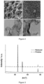
- the NiFe-hydroxide was vertically deposited onto the NF substrate with open area between nanosheet-like structures (refer Figure 1 ).
- a facile and economical chemical treatment was conducted by immersing the NiFe/NF electrode into a 1 M NaBH 4 solution for 20 minutes at room temperature, followed by washing with deionized water. Further details are given below.
- Nickel foam (purchased from Goodfellow, UK, 95% purity and 95% porosity) was sonicated in 5 M HCl for 30 minutes to remove nickel oxide layer and then rinsed with water and ethanol several times and left to dry in air.
- Ni-Fe electrodeposition was carried out by electrodeposition at 10 °C. Co-deposition of Ni and Fe was done with one electrolyte containing both metallic sources. Nitrate salt of Ni and Fe was used to make the electrodeposition electrolyte. To achieve a Ni-Fe alloy, 3 mM Ni(NO 3 ) 2 and 3 mM Fe(NO 3 ) 3 were dissolved in water without any additive. Ni/NF and Fe/NF was fabricated by electrodeposition of each metal from solution 6 mM of individual metal source.
- Equation 4 By applying electrical potential and according to Equation 4 nitrate ion reacts with water and produces hydroxide ions. The generated hydroxide ions then reacts with Ni and Fe ions in the electrolyte (Equation 5) and bimetallic hydroxide forms on the surface of electrodes. NO 3 - + 7H 2 O + 8e - ⁇ NH 4 + + 10OH - (4) xNi 2+ + yFe 3+ + (2x+3y)OH - ⁇ Ni 2x Fe 3y OH( 2x+3y ) (5)
- the electrode is washed and immersed in 1 M NaBH 4 solution for 20 minutes at room temperature. The electrode is then rinsed with water.
- NaBH 4 reduction mechanism can be explained by providing free electron in basic and neutral media according to Equation 6: BH 4 - + 8OH - ⁇ B(OH) 4 + 4H 2 O + 8e - (6)
- ECSA C DL / C S
- C DL is calculated from absolute average of slopes of lines in the plot of currents versus scan rates.
- the electrochemical experiments were performed under normal bench-top laboratory condition with a CH760 Electrochemical Workstation (CH Instrument, Texas, USA) using a three-electrode cell arrangement. Ag/AgCl electrode with 1 M KCl solution and Pt wire were used as the reference and counter electrode. CVs and LSVs measurement were performed with the scan rate of 5 mV.s -1 . Tafel slope determination was measured with the scan rate of 0.1 mV.s -1 . The electrochemical impedance spectroscopy (EIS) test was performed by B.A.S. potentiostat in a frequency range of 100 kHz to 0.01 Hz. All current densities in this specification were calculated by using the geometric surface area of the working electrode.
- EIS electrochemical impedance spectroscopy
- SEM was used for morphology studying by FEI Nova FESEM JEOL 7001F.
- XPS was performed on a Thermo ESCALAB250i X-ray Photoelectron Spectrometer.
- XRD was done on a PANalyticalX'Pert instrument and TEM performed using a Philips CM 200 microscope.
- Raman was carried out by Renishaw inVia Raman Microscope (510 nm).
- EPR was done by Bruker EMX X-Band EPR Spectrometer for NiFe/Cu samples since nickel has ferromagnetic properties and cannot be used as substrate.
- Ni-Fe Layered Double Hydroxide (NiFe-LDH) with carbon nanotube (CNT) support was synthesized by sonication of mildly oxidized multi-wall CNT and DMF and the mixing with Ni(NO 3 ) 2 and Fe(NO 3 ) 3 at 85 °C for 4 hours. Then more water and DMF was added to solution and the obtained solution was autoclaved for 12 hours at 120 °C followed by 2 more hours at 160 °C. Afterwards, the product was collected by filter.
- NiFe/NF Hydrothermally synthesized NiFe/NF also was made using the autoclave for 12 hours at 120 °C and then a 6 hour drying step at 80 °C.
- a nickel foam was inserted into the Teflon tube of the autoclave with a solution containing Ni(NO 3 ) 2 , Fe(NO 3 ) 3 and urea.
- X-ray diffraction (XRD) patterns of NiFe/NF and R-NiFe/NF electrodes show no other peaks apart from metallic nickel, suggesting that the materials deposited and after NaBH 4 reduction are both amorphous ( Figure 3 ). This was further confirmed by high-resolution transmission electron micros-copy (HRTEM) where no typical lattice fringes corresponding to Ni, Fe or NiFe composites were detected in Figure 2c and Figure 2d .
- Oxygen vacancy (OV) has been reported to play an important role in both photocatalysts and electrocatalysts towards water oxidation.
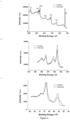
- Ni 2p Figure 4b
- Ni 3p Figure 4c
- the Ni 2 p 1 / 2 at 855.8 eV belongs to Ni(OH) 2
- peaks at 68.2 and 71.3 eV are attributed to Ni 2+ 3p 1 / 2 and Ni 3+ 3p 3 / 2 , respectively, revealing the coexistence of Ni 2+ /Ni 3+ states suggesting the NiOOH phase.
- the Fe 2p spectrum ( Figure 5a ) displays two major peaks at 724.78 and 711.58 eV with an obvious Fe 2 p 3 / 2 associated satellite peak at around 719.0 eV, indicating the iron atoms in the pristine samples are presented as Fe 3+ cations in phase of FeOOH.
- new peaks in Ni 2p (853.3 eV) and Fe 2p (707.6 eV) spectrums corresponding to metallic Ni and Fe, respectively, and a new broad shoulder in the Fe 3p spectrum ( Figure 4c ) which is attributed to Fe 2+ were observed in the R-NiFe/NF sample.
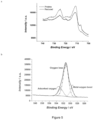
- the oxygen status in the NiFe (oxy)hydroxide before and after reduction was examined in the O1s core level spectra.
- the OV density formed can be estimated by taking the area of the peak ratio of oxygen loss to lattice oxygen. From Figure 6a and Figure 5b , the OV density in the R-NiFe/NF electrode is 7.0, which is almost doubled compared with that of 3.2 in the pristine electrode.
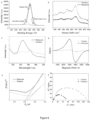
- E g for pristine NiFe composite deposit is 2.9 eV while it is 2.2 eV for reduced one (see Figure 6e ).
- the decreased band gap energy for treated Ni-Fe oxyhydroxide leads to higher conductivity due to more narrow electronic bands.
- reduction treatment of the electrode by NaBH 4 leads to less electrical resistance values which are also confirmed by electrical impedance spectroscopy (EIS).
- Figure 6f demonstrates the Nyquist plots for pristine and reduced OER electrodes for assessing the charge transfer process.
- the semi-circle curve of the obtained data reveals that the charge transfer resistance ( R ct ) is decreased from 79 to 36 ohm after the reduction treatment, indicating a faster charge transport of the reduced electrode.
- the pristine and reduced electrodes were directly used as OER working electrode and tested in an alkaline media using a standard three electrodes electrochemical cell set-up with scan rate of 5 mV.s -1 .
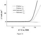
- OER performances of reduced and pristine NiFe/NF electrodes in 1 and 0.1 M KOH are shown in Figure 9a and 10 , respectively.
- the oxidation peak seen after 1.3 V (vs RHE) belongs to transformation between Ni(OH) 2 to NiOOH. Scanning to a higher anodic potential, a steady increase of oxygen evolution was accompanied by a significantly increased oxidation current for R-NiFe/NF electrode.
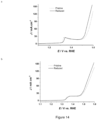
- Tafel slopes for the electrodes have also been evaluated.
- the Tafel slope of pristine and reduced electrode is, respectively, 47 and 40 mV.dec -1 in 1 M KOH, and 60 and 51 mV.dec -1 in 0.1 M KOH, which are less than for IrO 2 , RuO 2 .
- This small Tafel slope for reduced electrode further demonstrates the more efficient kinetics of water oxidation with less polarization loss.
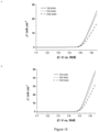
- the electrochemical surface area (ECSA) of R-NiFe/NF has been calculated and compared with the pristine electrode.
- the ECSA of each electrode is determined by double layer capacitance in 1 M KOH solution ( Figure 12 ). A roughness factor of 50 is determined for both pristine and reduced OER electrodes.
- Ni-Fe was first electrodeposited on glass carbon (GC) and then treated with NaBH 4 .
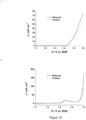
- the three consequent OER polarization curves investigated for the pristine and reduced NiFe electrodeposited onto the planar GC electrode in 1M KOH solution are shown in Figure 15 . It can be seen that the second polarization curve for both electrodes are significantly influenced by the gas bubbles generated on the first scan and consequently a significant decrease in the current occurs. However, when the bubbles attached on NiFe/GC electrode are removed, the catalytic activity of the NiFe/GC electrodes is recovered (third scan).
- Figure 9b shows the same effectiveness of NaBH 4 treatment for NiFe/GC electrode.
- Figure 9c exhibits a multi-step chronopotentiometric curve for R-NiFe/NF in 1M KOH.
- the current is increased from 100 to 550 mA.cm -2 in increments of 50 mA cm -2 every 500 s, and the corresponding changes of potential are recorded.
- the potential reaches 1.5 V gradually.
- the potential blooms at 1.55 V and remains constant for the remaining 500s. Similar behavior is seen for all current densities up to 550 mA.cm -2 during the test.
- the NaBH 4 reduction process was found useful for other OER catalysts made from different materials and methods.
- the effect of the reduction treatment on NiFe-LDH with carbon nano tube (CNT) support and on NiFe/NF synthesized by hydrothermal method has been investigated and significant enhancement of OER activity observed ( Figure 18 ).
- exposing the metallic composite coating to a reducing agent can be a fast and simple method to increase the OER electrocatalytic activity of metal hydroxide based catalysts by reduction of species on the surface of catalyst.
- a reducing agent e.g. NaBH 4 treatment
- the treatment creates some defects, in particular, oxygen vacancies, in the metal hydroxide catalyst structure and accordingly narrows the band gap energy, resulting in electrical conductivity enhancement of the materials.
- the inventors have found that introducing oxygen vacancy (OV) in R-NiFe/NF nanosheets improves its donor density, active sites and even decrease the energy required for H 2 O adsorption, thus enhancing the OER performance of R-NiFe/NF nanosheets.
- the direct chemical treatment of the Ni-Fe film on nickel foam as a 3D substrate not only provide it large surface area, fast charge transport pathways and improved contact resistance, but it also produces binder-free electrode for water-splitting or advanced metal-air battery devices.
- Using the reduced electrode, in accordance with the present invention as an anode, a surprisingly high OER activity (on R-NiFe/NF), which outperforms all the Ni-Fe based materials in alkaline previously reported, was observed.
Landscapes
- Chemical & Material Sciences (AREA)
- Engineering & Computer Science (AREA)
- Chemical Kinetics & Catalysis (AREA)
- Materials Engineering (AREA)
- Organic Chemistry (AREA)
- Electrochemistry (AREA)
- Metallurgy (AREA)
- Inorganic Chemistry (AREA)
- Catalysts (AREA)
- Electrodes For Compound Or Non-Metal Manufacture (AREA)
Applications Claiming Priority (2)
| Application Number | Priority Date | Filing Date | Title |
|---|---|---|---|
| AU2015904951A AU2015904951A0 (en) | 2015-11-30 | Method for improving catalytic activity | |
| PCT/AU2016/051178 WO2017091858A1 (en) | 2015-11-30 | 2016-11-30 | Method for improving catalytic activity |
Publications (3)
| Publication Number | Publication Date |
|---|---|
| EP3384070A1 EP3384070A1 (en) | 2018-10-10 |
| EP3384070A4 EP3384070A4 (en) | 2019-08-07 |
| EP3384070B1 true EP3384070B1 (en) | 2023-04-19 |
Family
ID=58796021
Family Applications (1)
| Application Number | Title | Priority Date | Filing Date |
|---|---|---|---|
| EP16869410.7A Active EP3384070B1 (en) | 2015-11-30 | 2016-11-30 | Method for improving catalytic activity |
Country Status (7)
| Country | Link |
|---|---|
| US (1) | US11141723B2 (enExample) |
| EP (1) | EP3384070B1 (enExample) |
| JP (1) | JP6893924B2 (enExample) |
| KR (1) | KR102771574B1 (enExample) |
| CN (1) | CN108291320B (enExample) |
| AU (1) | AU2016363676B2 (enExample) |
| WO (1) | WO2017091858A1 (enExample) |
Families Citing this family (42)
| Publication number | Priority date | Publication date | Assignee | Title |
|---|---|---|---|---|
| KR102077195B1 (ko) * | 2018-01-19 | 2020-02-13 | 대구대학교 산학협력단 | 망간-철의 나노복합체를 포함하는 산소 환원용 및 산소 발생용의 이중 기능성 전극 촉매 및 그의 제조 방법 |
| WO2019193486A1 (en) * | 2018-04-04 | 2019-10-10 | Zolfaghar Rezvani | Oxidation of water using layered double hydroxide catalysts |
| JP7423632B2 (ja) * | 2018-08-16 | 2024-01-29 | ニューサウス イノベーションズ ピーティーワイ リミテッド | 三金属層状複水酸化物組成物 |
| CN109569626A (zh) * | 2018-10-15 | 2019-04-05 | 华南理工大学 | 一种氧析出催化剂及由其制备的氧析出电极 |
| KR102201079B1 (ko) * | 2018-10-30 | 2021-01-08 | 인하대학교 산학협력단 | 산소발생용 니켈-철 산화물 촉매의 산소결핍의 유도 방법 및 그 방법에 의해 제조된 니켈-철 산화물 촉매 |
| KR102201082B1 (ko) * | 2018-10-30 | 2021-01-08 | 인하대학교 산학협력단 | 산소환원반응용 니켈-코발트 산화물의 산소결핍의 유도 방법 및 그 방법에 의한 니켈-코발트 산화물 |
| CN109847760B (zh) * | 2019-01-09 | 2022-06-03 | 济南大学 | 一种基于不锈钢纳米结构的三维电催化剂及其应用 |
| CN111686812B (zh) * | 2019-03-13 | 2023-04-07 | 北京大学深圳研究生院 | 配体活化的过渡金属层状双羟基化合物、制备方法及用途 |
| KR20200119953A (ko) | 2019-04-10 | 2020-10-21 | 울산과학기술원 | 이중층 페로브스카이트 물질로 구성된 고체 산화물 수전해셀용 촉매체, 이를 포함하는 고체 산화물 수전해셀, 및 그 제조 방법 |
| CN110129815B (zh) * | 2019-04-24 | 2020-10-16 | 北京大学深圳研究生院 | 改性的tm-ldh纳米材料、其制备方法及应用 |
| CN110124673B (zh) * | 2019-05-22 | 2020-05-05 | 复旦大学 | 一种硼诱导非晶层状双氢氧化物电催化剂及其制备与应用 |
| CN110197909B (zh) * | 2019-06-17 | 2021-05-25 | 中国科学院大连化学物理研究所 | 镍铁催化材料、其制备方法及在电解水制氢气、制备液态太阳燃料中的应用 |
| CN110327930B (zh) * | 2019-06-20 | 2022-02-18 | 武汉理工大学 | 低结晶分级羟基氧化镍纳米片阵列及其制备方法和应用 |
| CN110354862B (zh) * | 2019-08-14 | 2021-08-31 | 福州大学 | 泡沫镍基质表面铈离子辅助原位修饰三维镍铁水滑石电催化析氧电极的方法 |
| CN110433810B (zh) * | 2019-08-15 | 2021-09-10 | 青岛科技大学 | 氧化铜掺杂镍铁类水滑石纳米片/石墨烯双功能水分解催化剂的制备方法 |
| CN110538657B (zh) * | 2019-09-16 | 2021-08-31 | 福州大学 | 一种铁镍层状双氢氧化物及其制备方法和应用 |
| CN110947387B (zh) * | 2019-11-25 | 2022-07-01 | 中国工程物理研究院材料研究所 | 一种镍铁双金属氢氧化物纳米薄膜材料的制备方法及用途 |
| CA3177207A1 (en) * | 2020-05-04 | 2021-11-11 | University Of Delaware | An anion exchange membrane electrolyzer having a platinum-group-metal free self-supported oxygen evolution electrode |
| KR20210151282A (ko) | 2020-06-04 | 2021-12-14 | 울산과학기술원 | 이중층 페로브스카이트 물질로 구성된 고체 산화물 수계전해용 촉매체, 이를 포함하는 고체 산화물 수전해셀 |
| CA3181437A1 (en) * | 2020-06-05 | 2021-12-09 | Paul PEPIN | Activated carbon modified by atomic layer deposition and methods thereof |
| CN111628179B (zh) * | 2020-06-09 | 2022-07-05 | 澳门大学 | 一种电极材料、其制备方法和包含该电极材料的钠–空气电池 |
| CN111841567A (zh) * | 2020-08-04 | 2020-10-30 | 南通大学 | 一种具有图灵结构的镍锰羟基氧化物薄膜的制备方法及应用 |
| KR102763361B1 (ko) * | 2020-11-27 | 2025-02-11 | 롯데케미칼 주식회사 | 백금계 전극의 제조방법 |
| CN112593256B (zh) * | 2020-12-10 | 2021-08-20 | 吉林大学 | 一种核壳FeOOH@NiFe LDH电催化材料及制备方法 |
| CN112934221B (zh) * | 2021-02-01 | 2022-12-20 | 黑龙江省科学院石油化学研究院 | 一种镍铁水滑石负载型超细纳米钌催化剂及其制备方法 |
| KR102510307B1 (ko) * | 2021-02-05 | 2023-03-17 | 재단법인대구경북과학기술원 | 다공성 TiO 기반 인 시투 성장한 산소생성반용용 촉매 및 이의 제조방법 |
| KR102529278B1 (ko) * | 2021-02-24 | 2023-05-08 | (주)오운알투텍 | 니켈-철 합금 수소 발생 전극 및 이의 제조방법 |
| CN113136602A (zh) * | 2021-04-19 | 2021-07-20 | 西北师范大学 | 一种钒酸铋/Vo-FeNiOOH复合光阳极的制备及应用 |
| US11549188B2 (en) | 2021-04-28 | 2023-01-10 | Industrial Technology Research Institute | Membrane electrode assembly and method for hydrogen evolution by electrolysis |
| EP4349480A4 (en) * | 2021-05-26 | 2025-04-30 | Tokyo Institute of Technology | Catalyst, method for producing catalyst, and intermediate product |
| CN113502494B (zh) * | 2021-05-26 | 2022-06-21 | 浙江工业大学 | 高价态金属离子掺杂富含氧空位的氧化钴纳米复合材料及其制备与应用 |
| CN113355686B (zh) * | 2021-06-02 | 2022-04-19 | 宁波材料所杭州湾研究院 | 一种具有多层结构的纳米阵列材料、其制备方法与应用 |
| CN113667993B (zh) * | 2021-07-06 | 2022-10-11 | 浙江工业大学 | 一种富含氧空位的一氧化钴/铁酸钴纳米片阵列结构催化剂及其制备与应用 |
| CN113522298B (zh) * | 2021-07-12 | 2023-09-12 | 南京林业大学 | 一种钙钛矿氧化物/Ti3C2 MXene/泡沫镍复合材料及其制备方法和应用 |
| CN113526567A (zh) * | 2021-07-27 | 2021-10-22 | 湖南理工学院 | 一种酸蚀效应可控制备氧空位型金属氧化物的方法 |
| CN114016066A (zh) * | 2021-11-29 | 2022-02-08 | 西藏大学 | 一种Ni-Fe双金属硼化物纳米片阵列催化剂、其制备方法和应用 |
| JP2023152062A (ja) * | 2022-04-01 | 2023-10-16 | 時空化学株式会社 | 酸素発生電極、水の電気分解方法及び酸素発生電極の製造方法 |
| CN114927705B (zh) * | 2022-05-16 | 2023-10-27 | 内蒙古鄂尔多斯电力冶金集团股份有限公司 | 一种氧析出反应的自支撑无泡悬浮电极的制备方法 |
| CN114774968B (zh) * | 2022-05-31 | 2023-04-25 | 北京航空航天大学 | 一种泡沫镍负载NiFe非晶纳米阵列电催化电极及其制备方法 |
| CN114921797B (zh) * | 2022-06-21 | 2023-07-18 | 安阳工学院 | 重构氧空位的氧化物薄膜光电极及其制备方法 |
| CN116083952B (zh) * | 2023-03-28 | 2023-06-13 | 西南石油大学 | 一种Cu3Ti纳米片负载Ti掺杂CuO/Ru析氢反应催化剂及其制备方法 |
| CN118186484B (zh) * | 2024-05-16 | 2024-09-03 | 太原理工大学 | 一种Ir-Ni(OH)2/FeOOH@NF铱基催化剂及其制备方法及应用 |
Citations (1)
| Publication number | Priority date | Publication date | Assignee | Title |
|---|---|---|---|---|
| US20140294721A1 (en) * | 2013-03-29 | 2014-10-02 | Board Of Trustees Of The Leland Stanford Junior University | Doping and reduction of nanostructures and thin films through flame annealing |
Family Cites Families (17)
| Publication number | Priority date | Publication date | Assignee | Title |
|---|---|---|---|---|
| IL50217A (en) | 1976-08-06 | 1980-01-31 | Israel State | Electrocatalytically acitve spinel type mixed oxides |
| US4384928A (en) | 1980-11-24 | 1983-05-24 | Mpd Technology Corporation | Anode for oxygen evolution |
| JPS57116785A (en) | 1980-11-24 | 1982-07-20 | Mpd Technology | Electrode for generating gas from alkaline electrolyte and production thereof |
| US20050031921A1 (en) * | 2003-08-07 | 2005-02-10 | Ovshinsky Stanford R. | Hybrid fuel cell |
| WO2010146475A1 (en) * | 2009-06-18 | 2010-12-23 | University Of The Western Cape | Supported catalysts |
| ITMI20111132A1 (it) | 2011-06-22 | 2012-12-23 | Industrie De Nora Spa | Anodo per evoluzione di ossigeno |
| CN103974769B (zh) * | 2011-09-01 | 2018-11-09 | 西蒙·特鲁德尔 | 电催化材料及其制造方法 |
| KR101566458B1 (ko) | 2014-02-27 | 2015-11-05 | 한국과학기술연구원 | 산소 발생 반응 활성 향상 방법 및 이에 사용되는 니켈 촉매 |
| US9435043B2 (en) | 2014-04-14 | 2016-09-06 | California Institute Of Technology | Oxygen evolution reaction catalysis |
| JP2017527693A (ja) * | 2014-07-17 | 2017-09-21 | ザ ボード オブ トラスティーズ オブ ザ レランド スタンフォード ジュニア ユニバーシティー | 超活性水素放出電気触媒作用のためのヘテロ構造 |
| CN104183830A (zh) * | 2014-08-19 | 2014-12-03 | 中南大学 | 一种二维无机层状化合物/石墨烯复合材料的制备方法 |
| CN104659357A (zh) * | 2014-11-19 | 2015-05-27 | 北京化工大学 | 一种用于碱性水电解的负载型镍铁复合氢氧化物析氧电极及其制备方法 |
| CN104795493A (zh) | 2015-04-21 | 2015-07-22 | 东北师范大学 | 一种基于纳米线阵列的忆阻器及其制备方法 |
| CN104874389A (zh) | 2015-05-05 | 2015-09-02 | 上海应用技术学院 | 一种具有氧空位介孔WO3-x可见光催化剂及其制备方法和应用 |
| US20170127945A1 (en) * | 2015-11-11 | 2017-05-11 | George Ashford Reed | Respiratory Medicament and Therapy Data System and Method of Use |
| CN105251489A (zh) | 2015-09-13 | 2016-01-20 | 中南大学 | 一类铁基非贵金属析氧催化剂的制备方法 |
| PT3408023T (pt) * | 2016-01-29 | 2024-04-30 | Totalenergies Onetech | Catalisadores de oxi-hidróxido multimetálico homogeneamente disperso |
-
2016
- 2016-11-30 EP EP16869410.7A patent/EP3384070B1/en active Active
- 2016-11-30 WO PCT/AU2016/051178 patent/WO2017091858A1/en not_active Ceased
- 2016-11-30 AU AU2016363676A patent/AU2016363676B2/en active Active
- 2016-11-30 CN CN201680069638.8A patent/CN108291320B/zh active Active
- 2016-11-30 US US15/779,007 patent/US11141723B2/en active Active
- 2016-11-30 JP JP2018527210A patent/JP6893924B2/ja active Active
- 2016-11-30 KR KR1020187015184A patent/KR102771574B1/ko active Active
Patent Citations (1)
| Publication number | Priority date | Publication date | Assignee | Title |
|---|---|---|---|---|
| US20140294721A1 (en) * | 2013-03-29 | 2014-10-02 | Board Of Trustees Of The Leland Stanford Junior University | Doping and reduction of nanostructures and thin films through flame annealing |
Also Published As
| Publication number | Publication date |
|---|---|
| EP3384070A4 (en) | 2019-08-07 |
| JP2019505361A (ja) | 2019-02-28 |
| KR20180088654A (ko) | 2018-08-06 |
| WO2017091858A1 (en) | 2017-06-08 |
| CN108291320A (zh) | 2018-07-17 |
| US20180345266A1 (en) | 2018-12-06 |
| CN108291320B (zh) | 2021-06-22 |
| US11141723B2 (en) | 2021-10-12 |
| EP3384070A1 (en) | 2018-10-10 |
| JP6893924B2 (ja) | 2021-06-23 |
| AU2016363676A1 (en) | 2018-05-24 |
| AU2016363676B2 (en) | 2022-08-18 |
| KR102771574B1 (ko) | 2025-02-20 |
Similar Documents
| Publication | Publication Date | Title |
|---|---|---|
| EP3384070B1 (en) | Method for improving catalytic activity | |
| Jadhav et al. | An advanced and highly efficient Ce assisted NiFe-LDH electrocatalyst for overall water splitting | |
| Yang et al. | N-enriched porous carbon encapsulated bimetallic phosphides with hierarchical structure derived from controlled electrodepositing multilayer ZIFs for electrochemical overall water splitting | |
| AU2019322936B2 (en) | Trimetallic layered double hydroxide composition | |
| Liu et al. | N-doped graphitic carbon shell-encapsulated FeCo alloy derived from metal–polyphenol network and melamine sponge for oxygen reduction, oxygen evolution, and hydrogen evolution reactions in alkaline media | |
| Arshad et al. | Multifunctional porous NiCo bimetallic foams toward water splitting and methanol oxidation-assisted hydrogen production | |
| Li et al. | Halides-assisted electrochemical synthesis of Cu/Cu2O/CuO core-shell electrocatalyst for oxygen evolution reaction | |
| Hao et al. | Elucidating the superwetting FeOOH-modified NiMoO4 electrodes for efficient alkaline oxygen evolution reaction: An in-situ spectroscopy study | |
| Qian et al. | In situ quantification of the active sites, turnover frequency, and stability of Ni–Fe (Oxy) hydroxides for the oxygen evolution reaction | |
| Yang et al. | Electrochemical fabrication of 3D quasi-amorphous pompon-like Co-O and Co-Se hybrid films from choline chloride/urea deep eutectic solvent for efficient overall water splitting | |
| Kordek et al. | Cobalt-based composite films on electrochemically activated carbon cloth as high performance overall water splitting electrodes | |
| Li et al. | Electrodeposited ternary iron-cobalt-nickel catalyst on nickel foam for efficient water electrolysis at high current density | |
| Hameed et al. | Nickel oxide nanoparticles grown on mesoporous carbon as an efficient electrocatalyst for urea electro-oxidation | |
| Wang et al. | Boron modification promoting electrochemical surface reconstruction of NiFe-LDH for efficient and stable freshwater/seawater oxidation catalysis | |
| Rizk et al. | Tailor‐Designed Porous Catalysts: Nickel‐Doped Cu/Cu2O Foams for Efficient Glycerol Electro‐Oxidation | |
| Cheng et al. | Nitrogen-doped carbon armored Cobalt oxide hollow nanocubes electrochemically anchored on fluorine-doped tin oxide substrate for acidic oxygen evolution reaction | |
| Zheng et al. | Defective layered NiFe double hydroxides anchored on self-supported CoNi-nitrogen doped carbon nanotube composite as advanced electrocatalyst for oxygen evolution reaction | |
| Suleiman et al. | Rotating disk slurry electrodeposition of platinum at Y-zeolite/carbon Vulcan XC-72R for methanol oxidation in alkaline media | |
| Vidales et al. | Platinum nanoparticles supported on nickel-molybdenum-oxide for efficient hydrogen production via acidic water electrolysis | |
| Mousavi et al. | Sugar-cubic Fe2O3/nitrogen-doped graphene nanocomposite as high-performance anode material for oxygen evolution reaction | |
| Xiao et al. | Selective chromium dissolution as an interfacial design strategy for enhanced oxygen evolution activity in CrFeCoNi oxy-carbide films | |
| Ruan et al. | New insights into graphite paper as electrocatalytic substrate for oxygen evolution reaction | |
| Liu et al. | A facile route to efficient water oxidation electrodes via electrochemical activation of iron in nickel sulfate solution | |
| Bekisch et al. | Influence of pore size on mass transport: Bifunctional MnOx-coated nickel foam vs carbon corrosion prone commercial GDE in alkaline electrolyte | |
| Chai et al. | Cr (OH) 3 nanosheets@ ZIF67 electrocatalysts prepared by electrodeposition method for efficient oxygen evolution reaction |
Legal Events
| Date | Code | Title | Description |
|---|---|---|---|
| STAA | Information on the status of an ep patent application or granted ep patent |
Free format text: STATUS: THE INTERNATIONAL PUBLICATION HAS BEEN MADE |
|
| PUAI | Public reference made under article 153(3) epc to a published international application that has entered the european phase |
Free format text: ORIGINAL CODE: 0009012 |
|
| STAA | Information on the status of an ep patent application or granted ep patent |
Free format text: STATUS: REQUEST FOR EXAMINATION WAS MADE |
|
| 17P | Request for examination filed |
Effective date: 20180622 |
|
| AK | Designated contracting states |
Kind code of ref document: A1 Designated state(s): AL AT BE BG CH CY CZ DE DK EE ES FI FR GB GR HR HU IE IS IT LI LT LU LV MC MK MT NL NO PL PT RO RS SE SI SK SM TR |
|
| AX | Request for extension of the european patent |
Extension state: BA ME |
|
| DAV | Request for validation of the european patent (deleted) | ||
| DAX | Request for extension of the european patent (deleted) | ||
| A4 | Supplementary search report drawn up and despatched |
Effective date: 20190709 |
|
| RIC1 | Information provided on ipc code assigned before grant |
Ipc: B01J 37/18 20060101ALI20190703BHEP Ipc: B01J 23/755 20060101AFI20190703BHEP Ipc: B01J 35/04 20060101ALI20190703BHEP Ipc: C25B 1/04 20060101ALI20190703BHEP Ipc: C25B 11/04 20060101ALI20190703BHEP Ipc: B01J 25/02 20060101ALI20190703BHEP Ipc: B01J 23/74 20060101ALI20190703BHEP |
|
| REG | Reference to a national code |
Ref country code: HK Ref legal event code: DE Ref document number: 1261012 Country of ref document: HK |
|
| STAA | Information on the status of an ep patent application or granted ep patent |
Free format text: STATUS: EXAMINATION IS IN PROGRESS |
|
| 17Q | First examination report despatched |
Effective date: 20201201 |
|
| REG | Reference to a national code |
Ref country code: DE Ref legal event code: R079 Ref document number: 602016078953 Country of ref document: DE Free format text: PREVIOUS MAIN CLASS: C25B0011060000 Ipc: C25B0011073000 |
|
| GRAP | Despatch of communication of intention to grant a patent |
Free format text: ORIGINAL CODE: EPIDOSNIGR1 |
|
| STAA | Information on the status of an ep patent application or granted ep patent |
Free format text: STATUS: GRANT OF PATENT IS INTENDED |
|
| RIC1 | Information provided on ipc code assigned before grant |
Ipc: B01J 35/04 20060101ALI20220929BHEP Ipc: B01J 25/02 20060101ALI20220929BHEP Ipc: B01J 23/755 20060101ALI20220929BHEP Ipc: B01J 23/74 20060101ALI20220929BHEP Ipc: B01J 37/18 20060101ALI20220929BHEP Ipc: C25B 1/04 20060101ALI20220929BHEP Ipc: C25B 11/091 20210101ALI20220929BHEP Ipc: C25B 11/073 20210101AFI20220929BHEP |
|
| INTG | Intention to grant announced |
Effective date: 20221024 |
|
| GRAS | Grant fee paid |
Free format text: ORIGINAL CODE: EPIDOSNIGR3 |
|
| GRAA | (expected) grant |
Free format text: ORIGINAL CODE: 0009210 |
|
| STAA | Information on the status of an ep patent application or granted ep patent |
Free format text: STATUS: THE PATENT HAS BEEN GRANTED |
|
| AK | Designated contracting states |
Kind code of ref document: B1 Designated state(s): AL AT BE BG CH CY CZ DE DK EE ES FI FR GB GR HR HU IE IS IT LI LT LU LV MC MK MT NL NO PL PT RO RS SE SI SK SM TR |
|
| REG | Reference to a national code |
Ref country code: GB Ref legal event code: FG4D |
|
| REG | Reference to a national code |
Ref country code: CH Ref legal event code: EP |
|
| REG | Reference to a national code |
Ref country code: DE Ref legal event code: R096 Ref document number: 602016078953 Country of ref document: DE |
|
| REG | Reference to a national code |
Ref country code: IE Ref legal event code: FG4D |
|
| REG | Reference to a national code |
Ref country code: AT Ref legal event code: REF Ref document number: 1561232 Country of ref document: AT Kind code of ref document: T Effective date: 20230515 |
|
| P01 | Opt-out of the competence of the unified patent court (upc) registered |
Effective date: 20230524 |
|
| REG | Reference to a national code |
Ref country code: LT Ref legal event code: MG9D |
|
| REG | Reference to a national code |
Ref country code: NL Ref legal event code: MP Effective date: 20230419 |
|
| REG | Reference to a national code |
Ref country code: AT Ref legal event code: MK05 Ref document number: 1561232 Country of ref document: AT Kind code of ref document: T Effective date: 20230419 |
|
| PG25 | Lapsed in a contracting state [announced via postgrant information from national office to epo] |
Ref country code: NL Free format text: LAPSE BECAUSE OF FAILURE TO SUBMIT A TRANSLATION OF THE DESCRIPTION OR TO PAY THE FEE WITHIN THE PRESCRIBED TIME-LIMIT Effective date: 20230419 |
|
| PG25 | Lapsed in a contracting state [announced via postgrant information from national office to epo] |
Ref country code: SE Free format text: LAPSE BECAUSE OF FAILURE TO SUBMIT A TRANSLATION OF THE DESCRIPTION OR TO PAY THE FEE WITHIN THE PRESCRIBED TIME-LIMIT Effective date: 20230419 Ref country code: PT Free format text: LAPSE BECAUSE OF FAILURE TO SUBMIT A TRANSLATION OF THE DESCRIPTION OR TO PAY THE FEE WITHIN THE PRESCRIBED TIME-LIMIT Effective date: 20230821 Ref country code: NO Free format text: LAPSE BECAUSE OF FAILURE TO SUBMIT A TRANSLATION OF THE DESCRIPTION OR TO PAY THE FEE WITHIN THE PRESCRIBED TIME-LIMIT Effective date: 20230719 Ref country code: ES Free format text: LAPSE BECAUSE OF FAILURE TO SUBMIT A TRANSLATION OF THE DESCRIPTION OR TO PAY THE FEE WITHIN THE PRESCRIBED TIME-LIMIT Effective date: 20230419 Ref country code: AT Free format text: LAPSE BECAUSE OF FAILURE TO SUBMIT A TRANSLATION OF THE DESCRIPTION OR TO PAY THE FEE WITHIN THE PRESCRIBED TIME-LIMIT Effective date: 20230419 |
|
| PG25 | Lapsed in a contracting state [announced via postgrant information from national office to epo] |
Ref country code: RS Free format text: LAPSE BECAUSE OF FAILURE TO SUBMIT A TRANSLATION OF THE DESCRIPTION OR TO PAY THE FEE WITHIN THE PRESCRIBED TIME-LIMIT Effective date: 20230419 Ref country code: PL Free format text: LAPSE BECAUSE OF FAILURE TO SUBMIT A TRANSLATION OF THE DESCRIPTION OR TO PAY THE FEE WITHIN THE PRESCRIBED TIME-LIMIT Effective date: 20230419 Ref country code: LV Free format text: LAPSE BECAUSE OF FAILURE TO SUBMIT A TRANSLATION OF THE DESCRIPTION OR TO PAY THE FEE WITHIN THE PRESCRIBED TIME-LIMIT Effective date: 20230419 Ref country code: LT Free format text: LAPSE BECAUSE OF FAILURE TO SUBMIT A TRANSLATION OF THE DESCRIPTION OR TO PAY THE FEE WITHIN THE PRESCRIBED TIME-LIMIT Effective date: 20230419 Ref country code: IS Free format text: LAPSE BECAUSE OF FAILURE TO SUBMIT A TRANSLATION OF THE DESCRIPTION OR TO PAY THE FEE WITHIN THE PRESCRIBED TIME-LIMIT Effective date: 20230819 Ref country code: HR Free format text: LAPSE BECAUSE OF FAILURE TO SUBMIT A TRANSLATION OF THE DESCRIPTION OR TO PAY THE FEE WITHIN THE PRESCRIBED TIME-LIMIT Effective date: 20230419 Ref country code: GR Free format text: LAPSE BECAUSE OF FAILURE TO SUBMIT A TRANSLATION OF THE DESCRIPTION OR TO PAY THE FEE WITHIN THE PRESCRIBED TIME-LIMIT Effective date: 20230720 Ref country code: AL Free format text: LAPSE BECAUSE OF FAILURE TO SUBMIT A TRANSLATION OF THE DESCRIPTION OR TO PAY THE FEE WITHIN THE PRESCRIBED TIME-LIMIT Effective date: 20230419 |
|
| PG25 | Lapsed in a contracting state [announced via postgrant information from national office to epo] |
Ref country code: FI Free format text: LAPSE BECAUSE OF FAILURE TO SUBMIT A TRANSLATION OF THE DESCRIPTION OR TO PAY THE FEE WITHIN THE PRESCRIBED TIME-LIMIT Effective date: 20230419 |
|
| PG25 | Lapsed in a contracting state [announced via postgrant information from national office to epo] |
Ref country code: SK Free format text: LAPSE BECAUSE OF FAILURE TO SUBMIT A TRANSLATION OF THE DESCRIPTION OR TO PAY THE FEE WITHIN THE PRESCRIBED TIME-LIMIT Effective date: 20230419 |
|
| REG | Reference to a national code |
Ref country code: DE Ref legal event code: R097 Ref document number: 602016078953 Country of ref document: DE |
|
| PG25 | Lapsed in a contracting state [announced via postgrant information from national office to epo] |
Ref country code: SM Free format text: LAPSE BECAUSE OF FAILURE TO SUBMIT A TRANSLATION OF THE DESCRIPTION OR TO PAY THE FEE WITHIN THE PRESCRIBED TIME-LIMIT Effective date: 20230419 Ref country code: SK Free format text: LAPSE BECAUSE OF FAILURE TO SUBMIT A TRANSLATION OF THE DESCRIPTION OR TO PAY THE FEE WITHIN THE PRESCRIBED TIME-LIMIT Effective date: 20230419 Ref country code: RO Free format text: LAPSE BECAUSE OF FAILURE TO SUBMIT A TRANSLATION OF THE DESCRIPTION OR TO PAY THE FEE WITHIN THE PRESCRIBED TIME-LIMIT Effective date: 20230419 Ref country code: EE Free format text: LAPSE BECAUSE OF FAILURE TO SUBMIT A TRANSLATION OF THE DESCRIPTION OR TO PAY THE FEE WITHIN THE PRESCRIBED TIME-LIMIT Effective date: 20230419 Ref country code: DK Free format text: LAPSE BECAUSE OF FAILURE TO SUBMIT A TRANSLATION OF THE DESCRIPTION OR TO PAY THE FEE WITHIN THE PRESCRIBED TIME-LIMIT Effective date: 20230419 Ref country code: CZ Free format text: LAPSE BECAUSE OF FAILURE TO SUBMIT A TRANSLATION OF THE DESCRIPTION OR TO PAY THE FEE WITHIN THE PRESCRIBED TIME-LIMIT Effective date: 20230419 |
|
| PLBE | No opposition filed within time limit |
Free format text: ORIGINAL CODE: 0009261 |
|
| STAA | Information on the status of an ep patent application or granted ep patent |
Free format text: STATUS: NO OPPOSITION FILED WITHIN TIME LIMIT |
|
| 26N | No opposition filed |
Effective date: 20240122 |
|
| PG25 | Lapsed in a contracting state [announced via postgrant information from national office to epo] |
Ref country code: SI Free format text: LAPSE BECAUSE OF FAILURE TO SUBMIT A TRANSLATION OF THE DESCRIPTION OR TO PAY THE FEE WITHIN THE PRESCRIBED TIME-LIMIT Effective date: 20230419 |
|
| PG25 | Lapsed in a contracting state [announced via postgrant information from national office to epo] |
Ref country code: SI Free format text: LAPSE BECAUSE OF FAILURE TO SUBMIT A TRANSLATION OF THE DESCRIPTION OR TO PAY THE FEE WITHIN THE PRESCRIBED TIME-LIMIT Effective date: 20230419 Ref country code: IT Free format text: LAPSE BECAUSE OF FAILURE TO SUBMIT A TRANSLATION OF THE DESCRIPTION OR TO PAY THE FEE WITHIN THE PRESCRIBED TIME-LIMIT Effective date: 20230419 |
|
| REG | Reference to a national code |
Ref country code: CH Ref legal event code: PL |
|
| PG25 | Lapsed in a contracting state [announced via postgrant information from national office to epo] |
Ref country code: MC Free format text: LAPSE BECAUSE OF FAILURE TO SUBMIT A TRANSLATION OF THE DESCRIPTION OR TO PAY THE FEE WITHIN THE PRESCRIBED TIME-LIMIT Effective date: 20230419 |
|
| PG25 | Lapsed in a contracting state [announced via postgrant information from national office to epo] |
Ref country code: LU Free format text: LAPSE BECAUSE OF NON-PAYMENT OF DUE FEES Effective date: 20231130 |
|
| PG25 | Lapsed in a contracting state [announced via postgrant information from national office to epo] |
Ref country code: CH Free format text: LAPSE BECAUSE OF NON-PAYMENT OF DUE FEES Effective date: 20231130 |
|
| PG25 | Lapsed in a contracting state [announced via postgrant information from national office to epo] |
Ref country code: MC Free format text: LAPSE BECAUSE OF FAILURE TO SUBMIT A TRANSLATION OF THE DESCRIPTION OR TO PAY THE FEE WITHIN THE PRESCRIBED TIME-LIMIT Effective date: 20230419 Ref country code: LU Free format text: LAPSE BECAUSE OF NON-PAYMENT OF DUE FEES Effective date: 20231130 Ref country code: CH Free format text: LAPSE BECAUSE OF NON-PAYMENT OF DUE FEES Effective date: 20231130 |
|
| REG | Reference to a national code |
Ref country code: BE Ref legal event code: MM Effective date: 20231130 |
|
| REG | Reference to a national code |
Ref country code: IE Ref legal event code: MM4A |
|
| PG25 | Lapsed in a contracting state [announced via postgrant information from national office to epo] |
Ref country code: IE Free format text: LAPSE BECAUSE OF NON-PAYMENT OF DUE FEES Effective date: 20231130 |
|
| PG25 | Lapsed in a contracting state [announced via postgrant information from national office to epo] |
Ref country code: BE Free format text: LAPSE BECAUSE OF NON-PAYMENT OF DUE FEES Effective date: 20231130 |
|
| PG25 | Lapsed in a contracting state [announced via postgrant information from national office to epo] |
Ref country code: FR Free format text: LAPSE BECAUSE OF NON-PAYMENT OF DUE FEES Effective date: 20231130 |
|
| PG25 | Lapsed in a contracting state [announced via postgrant information from national office to epo] |
Ref country code: IE Free format text: LAPSE BECAUSE OF NON-PAYMENT OF DUE FEES Effective date: 20231130 Ref country code: FR Free format text: LAPSE BECAUSE OF NON-PAYMENT OF DUE FEES Effective date: 20231130 Ref country code: BE Free format text: LAPSE BECAUSE OF NON-PAYMENT OF DUE FEES Effective date: 20231130 |
|
| PG25 | Lapsed in a contracting state [announced via postgrant information from national office to epo] |
Ref country code: BG Free format text: LAPSE BECAUSE OF FAILURE TO SUBMIT A TRANSLATION OF THE DESCRIPTION OR TO PAY THE FEE WITHIN THE PRESCRIBED TIME-LIMIT Effective date: 20230419 |
|
| PG25 | Lapsed in a contracting state [announced via postgrant information from national office to epo] |
Ref country code: BG Free format text: LAPSE BECAUSE OF FAILURE TO SUBMIT A TRANSLATION OF THE DESCRIPTION OR TO PAY THE FEE WITHIN THE PRESCRIBED TIME-LIMIT Effective date: 20230419 |
|
| PGFP | Annual fee paid to national office [announced via postgrant information from national office to epo] |
Ref country code: DE Payment date: 20241126 Year of fee payment: 9 |
|
| PGFP | Annual fee paid to national office [announced via postgrant information from national office to epo] |
Ref country code: GB Payment date: 20241128 Year of fee payment: 9 |
|
| PG25 | Lapsed in a contracting state [announced via postgrant information from national office to epo] |
Ref country code: CY Free format text: LAPSE BECAUSE OF FAILURE TO SUBMIT A TRANSLATION OF THE DESCRIPTION OR TO PAY THE FEE WITHIN THE PRESCRIBED TIME-LIMIT; INVALID AB INITIO Effective date: 20161130 |
|
| PG25 | Lapsed in a contracting state [announced via postgrant information from national office to epo] |
Ref country code: HU Free format text: LAPSE BECAUSE OF FAILURE TO SUBMIT A TRANSLATION OF THE DESCRIPTION OR TO PAY THE FEE WITHIN THE PRESCRIBED TIME-LIMIT; INVALID AB INITIO Effective date: 20161130 |