EP3382244B1 - Solenoid valve, and method for manufacturing the solenoid valve - Google Patents
Solenoid valve, and method for manufacturing the solenoid valve Download PDFInfo
- Publication number
- EP3382244B1 EP3382244B1 EP18162967.6A EP18162967A EP3382244B1 EP 3382244 B1 EP3382244 B1 EP 3382244B1 EP 18162967 A EP18162967 A EP 18162967A EP 3382244 B1 EP3382244 B1 EP 3382244B1
- Authority
- EP
- European Patent Office
- Prior art keywords
- wall portion
- thickness
- core
- solenoid valve
- bottom wall
- Prior art date
- Legal status (The legal status is an assumption and is not a legal conclusion. Google has not performed a legal analysis and makes no representation as to the accuracy of the status listed.)
- Active
Links
Images






Classifications
-
- F—MECHANICAL ENGINEERING; LIGHTING; HEATING; WEAPONS; BLASTING
- F16—ENGINEERING ELEMENTS AND UNITS; GENERAL MEASURES FOR PRODUCING AND MAINTAINING EFFECTIVE FUNCTIONING OF MACHINES OR INSTALLATIONS; THERMAL INSULATION IN GENERAL
- F16K—VALVES; TAPS; COCKS; ACTUATING-FLOATS; DEVICES FOR VENTING OR AERATING
- F16K31/00—Actuating devices; Operating means; Releasing devices
- F16K31/02—Actuating devices; Operating means; Releasing devices electric; magnetic
- F16K31/06—Actuating devices; Operating means; Releasing devices electric; magnetic using a magnet, e.g. diaphragm valves, cutting off by means of a liquid
- F16K31/0675—Electromagnet aspects, e.g. electric supply therefor
-
- F—MECHANICAL ENGINEERING; LIGHTING; HEATING; WEAPONS; BLASTING
- F16—ENGINEERING ELEMENTS AND UNITS; GENERAL MEASURES FOR PRODUCING AND MAINTAINING EFFECTIVE FUNCTIONING OF MACHINES OR INSTALLATIONS; THERMAL INSULATION IN GENERAL
- F16K—VALVES; TAPS; COCKS; ACTUATING-FLOATS; DEVICES FOR VENTING OR AERATING
- F16K27/00—Construction of housing; Use of materials therefor
- F16K27/02—Construction of housing; Use of materials therefor of lift valves
- F16K27/029—Electromagnetically actuated valves
-
- B—PERFORMING OPERATIONS; TRANSPORTING
- B21—MECHANICAL METAL-WORKING WITHOUT ESSENTIALLY REMOVING MATERIAL; PUNCHING METAL
- B21D—WORKING OR PROCESSING OF SHEET METAL OR METAL TUBES, RODS OR PROFILES WITHOUT ESSENTIALLY REMOVING MATERIAL; PUNCHING METAL
- B21D22/00—Shaping without cutting, by stamping, spinning, or deep-drawing
- B21D22/20—Deep-drawing
-
- B—PERFORMING OPERATIONS; TRANSPORTING
- B21—MECHANICAL METAL-WORKING WITHOUT ESSENTIALLY REMOVING MATERIAL; PUNCHING METAL
- B21D—WORKING OR PROCESSING OF SHEET METAL OR METAL TUBES, RODS OR PROFILES WITHOUT ESSENTIALLY REMOVING MATERIAL; PUNCHING METAL
- B21D22/00—Shaping without cutting, by stamping, spinning, or deep-drawing
- B21D22/20—Deep-drawing
- B21D22/21—Deep-drawing without fixing the border of the blank
-
- B—PERFORMING OPERATIONS; TRANSPORTING
- B21—MECHANICAL METAL-WORKING WITHOUT ESSENTIALLY REMOVING MATERIAL; PUNCHING METAL
- B21D—WORKING OR PROCESSING OF SHEET METAL OR METAL TUBES, RODS OR PROFILES WITHOUT ESSENTIALLY REMOVING MATERIAL; PUNCHING METAL
- B21D53/00—Making other particular articles
-
- F—MECHANICAL ENGINEERING; LIGHTING; HEATING; WEAPONS; BLASTING
- F16—ENGINEERING ELEMENTS AND UNITS; GENERAL MEASURES FOR PRODUCING AND MAINTAINING EFFECTIVE FUNCTIONING OF MACHINES OR INSTALLATIONS; THERMAL INSULATION IN GENERAL
- F16K—VALVES; TAPS; COCKS; ACTUATING-FLOATS; DEVICES FOR VENTING OR AERATING
- F16K31/00—Actuating devices; Operating means; Releasing devices
- F16K31/02—Actuating devices; Operating means; Releasing devices electric; magnetic
- F16K31/06—Actuating devices; Operating means; Releasing devices electric; magnetic using a magnet, e.g. diaphragm valves, cutting off by means of a liquid
- F16K31/0644—One-way valve
- F16K31/0655—Lift valves
-
- H—ELECTRICITY
- H01—ELECTRIC ELEMENTS
- H01F—MAGNETS; INDUCTANCES; TRANSFORMERS; SELECTION OF MATERIALS FOR THEIR MAGNETIC PROPERTIES
- H01F7/00—Magnets
- H01F7/06—Electromagnets; Actuators including electromagnets
- H01F7/08—Electromagnets; Actuators including electromagnets with armatures
- H01F7/121—Guiding or setting position of armatures, e.g. retaining armatures in their end position
-
- H—ELECTRICITY
- H01—ELECTRIC ELEMENTS
- H01F—MAGNETS; INDUCTANCES; TRANSFORMERS; SELECTION OF MATERIALS FOR THEIR MAGNETIC PROPERTIES
- H01F7/00—Magnets
- H01F7/06—Electromagnets; Actuators including electromagnets
- H01F7/08—Electromagnets; Actuators including electromagnets with armatures
- H01F7/16—Rectilinearly-movable armatures
- H01F7/1607—Armatures entering the winding
Definitions
- This disclosure relates to a solenoid valve configured to attract a movable core upon energization of a hollow cylindrical solenoid part to thereby move a valve element, and a method for manufacturing the solenoid valve.
- a widely used solenoid valve is configured such that a fixed core made of magnetic material is inserted into one end of a hollow portion of a hollow cylindrical solenoid part and a movable core is inserted into the other end of the hollow portion of the solenoid part.
- Patent Document 1 JP 2003-172468 A discloses a solenoid valve configured such that a magnetic core is provided to form a magnetic circuit around a solenoid part, and a part of the magnetic core protrudes into the one end of the hollow portion of the solenoid part to form a hollow cylindrical fixed core provided with a bottom wall portion.
- US 5 746 412 A discloses an electromagnetic valve device according to the preamble of claim 1.
- JP 2002-143934 A discloses a die for drawing a drawn product.
- the document does not disclose at least the feature of claim 1 that the fixed core includes a peripheral wall portion formed such that a thickness of the peripheral wall portion near the bottom wall portion is as thick as 80% or more of a thickness of an outside plate portion of the magnetic core.
- Patent Document 1 discloses the solenoid valve and a manufacturing method thereof disclosed in Patent Document 1 .
- this protruding portion has a distal end portion having a thickness as thin as about 60% of the blank flat steel plate.
- the protruding portion is made by deep drawing to have such a length as to reach about a middle portion of the solenoid part, the distal end portion of the protruding portion becomes thinner.
- the protruding portion forms a magnetic circuit through which a magnetic flux generated by coil energization flows.
- a magnetic flux generated by coil energization flows.
- the solenoid part can generate large attraction force.
- a solenoid valve including a magnetic core having the thick protruding portion is large in size and heavy in weight, which is a problem that runs counter to the needs for downsizing of a solenoid valve.
- the present invention has been made to solve the above problems and has a purpose to provide a solenoid valve including a fixed core capable of reducing resistance of a magnetic circuit even when a magnetic core is made by a drawing process, and a manufacturing method of the solenoid valve.
- FIG. 3 is a perspective view of a solenoid valve 1 in the present embodiment.
- FIG. 1 is a cross-sectional view taken along a line A-A in FIG. 3
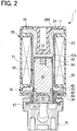
- FIG. 2 is a cross-sectional view taken along a line B-B in FIG. 3 .
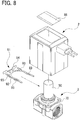
- FIG. 4 is an exploded perspective view of a part of a coil-core assembly.
- FIG 5 is an exploded perspective view of a body-pipe assembly.
- the coil-core assembly includes an upper core 10 having a nearly inverted U shape, a coil molded part 20 (one example of a solenoid part) containing a winding coil 23 embedded by molding, and a lower core 30.
- the upper core 10 and the lower core 30 are each made of ferromagnetic material to form a part of a magnetic circuit.
- the upper core 10 includes an upper plate portion 11 having a nearly rectangular shape and being formed, at its center, with a protruding portion 12 (one example of a fixed core) having a bottom-closed cylindrical shape protruding downward in FIG. 4 .
- the upper core 10 further includes four side plate portions 13 continuously extending downward two from each of two opposite side edges of the upper plate portion 11.
- the protruding portion 12 has a hollow cylindrical shape provided with a bottom wall portion 12a at a distal end (a lower end in the figures) and an opening, or open end, at a proximal end (an upper end in the figures).
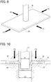
- FIGs. 9 , 11, and 12 are diagrams to show a processing method for subjecting a flat steel plate 14 made of ferromagnetic material to a drawing process. Specifically, FIGs. 11 and 12 are cross-sectional diagrams to show a fourth step and a fifth step. FIG. 10 is a diagram to show a conventional drawing process.
- the conventional drawing process is performed by fixedly clamping a portion of a flat steel plate (a blank) except a portion to be drawn between a pair of an upper die 16 and a lower die 15 applied with a high force F3 and then moving a punch 17 downward to draw or stretch the blank.
- the thickness of the clamped portion of the flat steel plate other than the drawn portion is not reduced, and only the drawn portion is stretched thinner to form a hollow portion having a bottom wall portion.
- the drawing process in the present embodiment will be described below. As shown in FIGs. 9 , 11, and 12 , the present drawing process uses only a lower die without using an upper die. In the present embodiment, the drawing process for forming the protruding portion 12 is performed sequentially in five steps; a first step, a second step, and a third step, which are not illustrated, a fourth step shown in FIG. 11 and a fifth step shown in FIG. 12 .
- An end face of the processing hole of the lower die is formed with a tapered surface.
- the flat steel plate 14 is thus formed into a truncated cone shape.
- a punch having the diameter smaller than the diameter of the punch used in the first step and a lower die with a processing hole having the inner diameter smaller than the inner diameter of the lower die used in the first step.
- An end face of the processing hole of the lower die in this second step is formed with a more steeply tapered surface than in the first step to form the truncated-conical flat steel plate 14 into a shape close to a cylindrical shape.
- a punch having the diameter smaller than the diameter of the punch used in the second step and a lower die with a processing hole having the inner diameter smaller than the inner diameter of the lower die used in the second step.
- An end face of the processing hole of the lower die in this third step is formed with a still more steeply tapered surface than in the second step to further form the truncated-conical flat steel plate 14 into a shape closer to a cylindrical shape,
- FIG. 11 is a diagram showing a fourth step of the drawing process.
- a punch 18D used in the fourth step has the diameter d5 larger than the diameter of the punch used in the third step and a lower die 15D used in the fourth step has a processing hole having the inner diameter D5 larger than the inner diameter of the lower die used in the third step.
- the processing hole in the fourth step is cylindrical.
- forces F1 and F2 are externally exerted on the flat steel plate 14, or its end faces, from lateral directions. However, if the thickness W1 of a peripheral, or side, wall portion 12b of the protruding portion 12 near the bottom wall portion 12a is as thick as necessary, the forces F1 and F2 do not need to be externally applied.
- FIG. 12 is a diagram showing a fifth step of the drawing process.
- a lower slide die 19 which slides inside the processing hole of the lower die 15D moves upward in a state shown in FIG. 11 , pushing up the flat steel plate and pressing it against the punch 18D to arrange the shape of the bottom (12a) of the flat steel plate.
- the protruding length of the protruding portion 12 is appropriately determined so that its distal end protrudes into the hollow portion of the coil molded part 20 (a hollow hole 24A of the coil bobbin 24) by a distance equal to or more than one third of the axial length of the hollow portion.
- the protruding portion 12 is finished.
- the peripheral wall portion 12b of the protruding portion 12 near the bottom wall portion 12a is most stretched and thinned to a thickness W1.
- a portion of the flat steel plate other than a portion to be drawn (a drawn portion) which will form the peripheral wall portion 12b is unclamped between upper and lower dies, so that metal material of the portion other than the drawn portion is allowed to move toward the drawn portion undergoing stretching downward.
- the thickness W3 of the peripheral wall portion 12b near the open end (a proximal end side) far from the bottom wall portion 12a (a distal end side) is thicker than the thickness W2 of the flat steel plate used as the blank. This ensures that the thickness W1 of the peripheral wall portion 12b near the bottom wall portion 12a is as thick as 80% or more of the thickness W2 of the blank, flat steel plate.
- the diameter d5 of the punch 18D is set smaller than the diameter d1 of the punch 17 in FIG. 10 in order to prevent contact with the inner surface of the peripheral wall portion 12b of the protruding portion 12 near the open end far from the bottom wall portion 12a. This is because, in the drawing process, the forces F1 and F2 are applied as shown in FIG. 9 to cause metal material to flow to the protruding portion 12 in order to prevent thinning of the peripheral wall portion 12b and thus the inner diameter of the protruding portion 12 is reduced.
- the coil molded part 20 is made in such a manner that the coil 23 is wound on the outer periphery of the plastic hollow coil bobbin 24, and then this coil bobbin 24 with the coil 23 wound thereon is coated with resin by insert molding to form a molded portion 21.
- the coil molded part 20 is provided with external connecting terminals 22 which serve to electrically connect the coil 23 to an external power supply.
- the protruding portion 12 of the upper core 10 is inserted from above into the hollow hole 24A of the coil bobbin 24 which constitutes the hollow portion of the coil molded part 20.
- the lower core 30 includes a bottom plate portion 31 having a nearly rectangular shape, at the center of which, there is formed a protruding portion 32 cylindrically protruding upward in FIG. 4 .
- the lower core 30 further includes side plate portions 33 extending upward one from each of two opposite side edges of the bottom plate portion 31, i.e., toward the side plate portions 13 of the upper core 10, and a pair of inwardly-bent flanges 34 formed one in each of two opposite side edges of the bottom plate portion 31 other than the side edges formed with the side plate portions 33.
- Each of the flanges 34 has a laterally-facing U-shaped cross section and is open inward as shown in FIG. 2 .
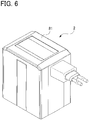
- the protruding portion 32 of the lower core 30 is inserted into the hollow hole 24A of the coil bobbin 24 from below. While the coil molded part 20 is held between the upper core 10 and the lower core 30, the leading ends of the side plate portions 13 are welded to the corresponding side plate portions 33. Thus, a coil-core assembly is completed. This coil-core assembly is then coated with resin by insert molding to form a molded portion 81. A coil assembly 2 shown in FIG. 6 is finished.
- a body-pipe assembly 3 is successively described below. As shown in FIGs. 1 , 2 , and 5 , a stuffing 40 serving as a fastening tool is secured to a body (a valve body) 70 with four screws not shown while a flare pipe 50 and an O ring 69 are held therebetween.
- the stuffing 40 has a nearly square plate-like shape formed with screw holes 45 in four corners. At the center of the stuffing 40, a circumferential side wall 42 protruding upward. This side wall 42 is provided, at its leading end (an upper end in FIG. 5 ), with a bent portion 43 bent radially outwardly over the entire circumference of the side wall 42.
- the flare pipe 50 includes a hollow cylindrical portion 51 closed by a top face (a top wall) 55 and a large-diameter portion 53 having a larger diameter than the cylindrical portion 51 by a diameter-widening portion 52.
- This diameter-widening portion 52 perpendicularly extends radially outward from the cylindrical portion 51 to the large-diameter portion 53 so that the cylindrical portion 51 and the large-diameter portion 53 are parallel with each other.
- the large-diameter portion 53 is provided, at its lower end, with a flange 54 extending radially outward.
- the flare pipe 50 is made of magnetic material, which will form a part of a magnetic circuit.
- a cylindrical compression spring 59 is accommodated inside the large-diameter portion 53.
- a plunger 60 serving as a movable core includes a plunger body 61 made of ferromagnetic material.
- the plunger body 61 is formed, at the center of its upper face, with a hole in which a silencing rubber 64 is mounted to protrude from the upper face.
- the silencing rubber 64 serves to reduce impact noise generated when the plunger 60 is attracted toward the protruding portion 12 and strikes or collides against an inner surface of the top face 55 of the flare pipe 50.
- the plunger body 61 is formed with a plastic upper wear ring 63 circumferentially placed on an upper part of an outer peripheral surface.
- the upper wear ring 63 protrudes radially outward at regular intervals.
- the plunger body 61 is further formed, on its upper face, with a plastic ring 63a having a plurality of projections protruding outward in an axial direction (upward in the figures).
- the plastic ring 63a is provided integral with the upper wear ring 63 by integral molding.
- the ring 63a can mitigate the impact caused when the plunger 60 is attracted as above. This can prevent breakage of the flare pipe 50 and also enhance the returning property of the plunger body 61.
- the plunger body 61 is provided, at its lower end, with a valve element holder 68 made of resin by integral molding.
- a lower wear ring 65 protruding radially outward is arranged in a position above the lower end of the cylindrical portion 51 of the flare pipe 50 facing the holder 68.
- the upper wear ring 63 and the lower wear ring 65 each protruding radially outward as described above are in contact with an inner peripheral surface 51a of the cylindrical portion 51.
- a clearance of about 0.5 mm is thus formed, even though it is not explicitly illustrated in the figures, between an outer peripheral surface 61a of the plunger body 61 and the inner peripheral surface 51a of the cylindrical portion 51.
- the outer peripheral surface 61a of the plunger body 61 is not in contact with the inner peripheral surface 51a of the cylindrical portion 51.
- the plunger body 61 and the cylindrical portion 51 do not slide or rub against each other during operation. This can prevent deterioration of sliding surfaces due to repeated operations and generation of abrasion powder which may increase sliding resistance, leading to operation failure.
- the above clearance acts as magnetic resistance to a magnetic flux laterally flowing from the outer peripheral surface 61a of the plunger boy 61 to the inner peripheral surface 51a of the cylindrical portion 51. Accordingly, the attraction force generated between the inner peripheral surface 51a of the cylindrical portion 51 and the outer peripheral surface 61a of the plunger body 61 can be reduced.
- the valve element holder 68 is provided with a flange 67 protruding radially outward from a lower end of the outer periphery of the holder 68.
- a cavity 66 is formed in the holder 68, in which a rubber valve element 75 is mounted.
- the body 70 is provided with a first passage 71 and a second passage 72. These first passage 71 and second passage 72 are communicated with each other through a valve hole in which a valve seat 73 is provided. When the valve element 75 is moved into contact with the valve seat 73, the first passage 71 and the second passage 72 are blocked from communicating with each other. On the other hand, when the valve element 75 is separated from the valve seat 73, the first passage 71 and the second passage 72 are allowed to communicate with each other.
- the plunger 60 is slidably held within the flare pipe 50 through the upper wear ring 63 and the lower wear ring 65.
- the upper end of the compression spring 59 is abutted on the inner surface of the diameter-widening portion 52 of the flare pipe 50 and the lower end of the compression spring 59 is abutted on the flange 67 of the plunger 60.
- the compression spring 59 urges the plunger 60 in a direction to move the valve element 75 into contact with or toward the valve seat 73.
- the diameter-widening portion 52 is perpendicular to each of the cylindrical portion 51 and the large-diameter portion 53.
- the compression spring 59 is stably abutted on the inner surface of the diameter-widening portion 52. This can stabilize the urging force of the compression spring 59 and achieve a stable motion of the plunger 60. Accordingly, variation in response speed of the solenoid valve 1 can be reduced and hence constant response timing can be realized. Specifically, when the plunger 60 is to be attracted toward the protruding portion 12, the plunger 60 is moved by the magnetic force generated by energization of the coil 23 (the coil molded part 20), so that the timing of driving the plunger 60 is stable.
- the force of the compression spring 59 is weaker than the attraction force of the coil molded part 20 and the plunger 60 is attracted toward the protruding portion 12 by residual magnetism, thereby possibly causing a delay in the driving timing of moving the plunger 60 downward. To prevent such a delay, the urging force of the compression spring 59 highly needs to be stabilized.
- the compression spring 59 may enter the clearance between the plunger 60 and the cylindrical portion 51, leading to operation failure. To prevent such a defect, it is also necessary to stabilize the position of the compression spring 59.
- the stuffing 40 is secured to the body 70 with four screws not shown while the flare pipe 50 and the O ring 69 are held between the stuffing 40 and the body 70.
- the body-pipe assembly 3 shown in FIG. 7 (the screws are not shown) is finished.
- the flare pipe 50 of the body-pipe assembly 3 is inserted into the hollow hole 24A of the coil assembly 2 from below.
- a clip 91 is then placed in position to couple the coil assembly 2 and the body-pipe assembly 3.
- the clip 91 is made by press working of a resilient stainless-steel sheet having a thickness of about 1 mm.
- the clip 91 includes a nearly U-shaped clip body 92 and a pair of lugs 94 which can be pinched by an operator.
- the clip body 92 is provided with four leaf springs 93 extending outward. Each of the leaf springs 93 is bent into an inverted triangular shape when seen from side ( FIG. 14 ) and thus has a spring force acting in an up-down direction.
- the clip body 92 is inserted in the space between each inwardly-bent flange 34 of the lower core 30 of the coil assembly 2 and a bent portion 43 of the stuffing 40 of the body-pipe assembly 3.
- FIG. 13 is a cross-sectional view showing the clip 91 set in position.
- FIG. 14 shows a positional relationship between the clip 91, the bent portion 43, and the inwardly-bent flanges 34.
- a part of the upper surface of the clip body 92 presses against the lower surface of the bent portion 43 of the stuffing 40.
- the apex portions of the four triangular bent leaf springs 93 are abutted on the upper surfaces of the inwardly-bent flanges 34 of the lower core 30.
- the leaf springs 93 are designed to generate a spring force of 15N to 25N per each leaf spring and 60N to 100N by a total of four leaf springs.
- a coil assembly and a body-pipe assembly are coupled to each other for example by inserting a fixed core welded to an upper end of a hollow portion of a guide pipe of the body-pipe assembly through a hollow hole of a drive unit and fixing the fixed core at the upper end with a stopper ring. At that time, a wave washer is inserted between the coil assembly and the body-pipe assembly to urge the coil assembly upward.
- the conventional method has problems that the number of components is large and a coupling portion is provided in the upper part of a solenoid part. This method is therefore inapplicable to a configuration that a fixed core does not extend through a solenoid part.
- the coil assembly 2 and the body-pipe assembly 3 can be coupled to each other by use of only the clip 91 having a spring force in combination with the inwardly-bent flanges 34 of the lower core 30 and the coil assembly 2 and the bent portion 43 of the stuffing 40 of the body-pipe assembly 3.
- the number of components can be reduced.
- FIG. 15 shows the magnetic circuit in the solenoid valve 1 and corresponds to FIG. 1 , from which hatching lines are omitted.
- a magnetic flux S is limited by the thickness W1 of the peripheral wall portion, which is smallest in cross-sectional area as shown in FIG. 12 , of the protruding portion near the bottom wall portion.
- the thickness W1 of the peripheral wall portion near the bottom wall portion is as thick as 80% or more of the thickness W2 of the flat steel plate used as a blank. Accordingly, a sufficient magnetic flux can be generated and thus the attraction force of the solenoid part is not decreased.
- the solenoid valve can maintain the response for opening at the high level.
- the flare pipe 50 is made of magnetic material for the following reason.
- the guide pipe for guiding the plunger is made of magnetic metal, usually, the outer peripheral surface of the plunger is attracted to the guide pipe and hence a large sliding resistance is generated therebetween. To avoid such a resistance, therefore, the guide pipe is made of non-magnetic material.
- the flare pipe 50 is made of magnetic metal. Accordingly, when a magnetic flux flows through the flare pipe 50 made of magnetic metal, increasing a transverse attraction force applied to the plunger 60 enclosed in the cylindrical portion 51 of the flare pipe 50, the plunger body 61 slides against the cylindrical portion 51. Repetition of this sliding motion may deterioration of their sliding surfaces and generation of abrasion powder leading to an increase in sliding resistance, resulting in operation failure.
- the upper wear ring 63 and the lower wear ring 65 are arranged in contact with the inner peripheral surface 51a of the cylindrical portion 51 to form a clearance of about 0.5 mm between the outer peripheral surface 61a of the plunger body 61 and the inner peripheral surface 51a of the cylindrical portion 51.
- This clearance serves as a magnetic resistance to the magnetic flux M laterally flowing from the outer peripheral surface 61a of the plunger body 61 to the inner peripheral surface 51a of the cylindrical portion 51. This can reduce the attraction force to be generated between the inner peripheral surface 51a of the cylindrical portion 51 and the outer peripheral surface 61a of the plunger body 61.
- the solenoid valve 1 includes the hollow cylindrical coil molded part 20, the plunger 60, and the valve element 75, in which the plunger 60 is attracted upon energization of the coil molded part 20 to move the valve element 75.
- the solenoid valve 1 further includes the magnetic core (the upper core 10 and the lower core 30) surrounding the coil molded part 20 to form a magnetic circuit. A part of the upper core 10 protrudes into the hollow portion (24A) of the coil molded part 20 to form the hollow cylindrical protruding portion 12 provided with the bottom wall portion 12a at a distal end.
- the protruding portion 12 includes the peripheral wall portion 12b formed such that the thickness W1 of the peripheral wall portion 12b near the bottom wall portion 12a is as thick as 80% or more of the thickness W2 of the upper plate portion (the outside plate portion) 11 of the upper core 10, located outside the coil molded part 20 in the axial direction thereof.
- the thickness W1 of the peripheral wall portion 12b of the protruding portion 12 near the bottom wall portion 12a can be as thick as 80% or more of the thickness W2 of the upper plate portion 11.
- a decreasing amount of a magnetic flux S flowing through the magnetic circuit can be reduced and hence the attraction force of the coil molded part 20 can be prevented from deteriorating. Consequently, the response property of the solenoid valve 1 can be enhanced.
- the flat steel plate 14 used as a blank for forming the upper plate portion 11 does not need to be thick, the needs for downsizing of the solenoid valve 1 can be satisfied.
- the protruding portion 12 has a protruding length to protrude into the hollow portion 24A by a distance equal to or longer than one third of a length of the hollow portion 24A of the coil molded part 20 in the axial direction. Accordingly, when the protruding portion 12 is made by deep drawing so that its protruding length is equal to or more than one third of the axial length of the hollow portion 24A of the coil molded part 20, the thickness of the peripheral wall portion 12b of the protruding portion 12 near the bottom wall portion 12a of the protruding portion 12 is apt to be thin, which is problematic.
- the thickness W1 of the peripheral wall portion 12b of the protruding portion 12 near the bottom wall portion 12a is as thick as 80% or more of the thickness W2 of the upper plate portion 11. This can reduce a decreasing amount of the magnetic flux S flowing through the magnetic circuit, and hence enhance the response property of the solenoid valve 1. Since the thickness of the flat steel plate 14 used as a blank for forming the upper core 10 does not need to be thick, the needs for downsizing the solenoid valve 1 can be met.
- the protruding portion 12 is formed of the flat steel plate 14 subjected to a drawing process more than once.
- a portion of the flat steel plate 14 other than a portion to be drawn (a drawn portion) is not clamped down to allow the material of the unclamped portion to flow to the drawn portion.
- the thickness W1 of the peripheral wall portion 12b of the protruding portion 12 near the bottom wall portion 12a can be as thick as 80% or more of the thickness W2 of the outer plate portion 11.
- the end faces of the flat steel plate 14 may be applied with a force for causing the material to flow to the drawn portion.
- the thickness W1 of the peripheral wall portion 12b of the protruding portion 12 near the bottom wall portion 12a can be easily made to be 80% or more of the thickness W2 of the outer plate portion 11.
- the method for manufacturing the solenoid valve in the present embodiment can provide the following operations and effects.
- the solenoid valve 1 includes the magnetic core (the upper core 10 and the lower core 30) surrounding the coil molded part 20 to form a magnetic circuit.
- the method includes subjecting the flat steel plate 14 to a drawing process more than once so that a part of the upper core 10 protrudes into the hollow portion 24A of the coil molded part 20 to form the hollow cylindrical protruding portion 12 provided with the bottom wall portion 12a at its distal end.
- the thickness W1 of the peripheral wall portion 12b of the protruding portion 12 near the bottom wall portion 12a can be made to be as thick as 80% or more of the thickness W2 of the upper plate portion 11 of the upper core 10. This can reduce a decreasing amount of a magnetic flux S generated in the magnetic circuit and enhance the response property. Further, since the thickness of the flat steel plate 14 used as a blank for forming the upper core 10 does not need to be thick, the needs for downsizing the solenoid valve 1 can be satisfied.
- the protruding portion 12 has a protruding length to protrude into the hollow portion by a distance equal to or longer than one third of the length of the hollow portion of the coil molded part 20 in the axial direction.
- the protruding portion 12 includes the peripheral wall portion 12b having the thickness W1 near the bottom wall portion 12a, the thickness W1 being 80% or more of the thickness W2 of the upper plate portion 11. Accordingly, a decreasing amount of a magnetic flux S generated in the magnetic circuit can be reduced and hence the response property can be enhanced. Further, since the thickness of the flat steel plate used as a blank for forming the upper core 10 does not need to be thick, the needs for downsizing the solenoid valve 1 can be satisfied.
- the protruding portion 12 has a protruding length to protrude into the hollow portion of the coil molded part 20 by a distance equal to or longer than one third of a length of the hollow portion of the coil molded part 20 in the axial direction.
- the protruding portion 12 is made by deep drawing so that the protruding length is equal to or more than one third of the axial length of the hollow portion of the coil molded part 20, the thickness W1 of the peripheral wall portion 12b of the protruding portion 12 near the bottom wall portion 12a is apt to be thin, which is problematic.
- the thickness W1 of the peripheral wall portion 12b of the protruding portion 12 near the bottom wall portion 12a is made as thick as 80% or more of the thickness W2 of the upper plate portion 11. This can reduce a decreasing amount of a magnetic flux S flowing through the magnetic circuit. Since the thickness of the flat steel plate 14 used as a blank does not need to be thick, the needs for downsizing the solenoid valve 1 can be satisfied.
- the drawing process may be performed more than or less than five steps.
- the distal end of the protruding portion 12 has the protruding length to protrude into the hollow portion of the coil molded part 20 by a distance equal to or more than one third of the axial length of the hollow portion.
- the protruding portion 12 only needs to protrude into the hollow portion until the distal end of the protruding portion 12 reaches a middle portion of the coil molded part 20.
Landscapes
- Engineering & Computer Science (AREA)
- General Engineering & Computer Science (AREA)
- Mechanical Engineering (AREA)
- Physics & Mathematics (AREA)
- Electromagnetism (AREA)
- Power Engineering (AREA)
- Magnetically Actuated Valves (AREA)
- Electromagnets (AREA)
Applications Claiming Priority (1)
| Application Number | Priority Date | Filing Date | Title |
|---|---|---|---|
| JP2017061555A JP6533803B2 (ja) | 2017-03-27 | 2017-03-27 | 電磁弁、及び電磁弁の製造方法 |
Publications (2)
| Publication Number | Publication Date |
|---|---|
| EP3382244A1 EP3382244A1 (en) | 2018-10-03 |
| EP3382244B1 true EP3382244B1 (en) | 2021-01-20 |
Family
ID=61731635
Family Applications (1)
| Application Number | Title | Priority Date | Filing Date |
|---|---|---|---|
| EP18162967.6A Active EP3382244B1 (en) | 2017-03-27 | 2018-03-20 | Solenoid valve, and method for manufacturing the solenoid valve |
Country Status (5)
| Country | Link |
|---|---|
| EP (1) | EP3382244B1 (https=) |
| JP (1) | JP6533803B2 (https=) |
| KR (1) | KR102192456B1 (https=) |
| CN (1) | CN108662251B (https=) |
| TW (1) | TWI704311B (https=) |
Families Citing this family (7)
| Publication number | Priority date | Publication date | Assignee | Title |
|---|---|---|---|---|
| JP7072831B2 (ja) * | 2017-11-30 | 2022-05-23 | アドバンス電気工業株式会社 | 電磁弁 |
| KR102205611B1 (ko) * | 2019-09-24 | 2021-01-21 | (주)솔텍 | Ptc 소자를 이용한 고압 솔레노이드 밸브의 온오프 제어방법 |
| KR102205609B1 (ko) * | 2019-09-24 | 2021-01-21 | (주)솔텍 | 이중 코일 구조를 갖는 고압 솔레노이드 밸브 |
| JP7339839B2 (ja) * | 2019-10-07 | 2023-09-06 | Ckd株式会社 | 電磁弁 |
| WO2021211262A2 (en) * | 2020-04-13 | 2021-10-21 | Parker-Hannifin Corporation | Low profile miniature solenoid proportional valve with safety encapsulation |
| KR20230088155A (ko) * | 2021-12-10 | 2023-06-19 | 현대자동차주식회사 | 솔레노이드 밸브 |
| KR20240139844A (ko) | 2023-03-15 | 2024-09-24 | 신한정공주식회사 | 연료전지 차량용 밸브 조립체 |
Family Cites Families (12)
| Publication number | Priority date | Publication date | Assignee | Title |
|---|---|---|---|---|
| JPS5012565A (https=) * | 1973-06-08 | 1975-02-08 | ||
| DE2427201A1 (de) * | 1974-06-05 | 1976-01-02 | Kuhnke Gmbh Kg H | Elektromagnetisch betaetigtes ventil |
| JPS565234Y2 (https=) * | 1980-03-07 | 1981-02-04 | ||
| JP3016055B2 (ja) * | 1993-07-13 | 2000-03-06 | 日信工業株式会社 | 電磁アクチュエータ |
| JPH0893947A (ja) * | 1994-09-28 | 1996-04-12 | Aisin Seiki Co Ltd | 電磁弁装置およびその製造方法 |
| JP2001235050A (ja) * | 2000-02-23 | 2001-08-31 | Uchida Soki Co Ltd | ソレノイドおよびその製造方法 |
| JP3622667B2 (ja) * | 2000-11-08 | 2005-02-23 | セイコーエプソン株式会社 | 金型 |
| JP2002317882A (ja) * | 2001-04-20 | 2002-10-31 | Aisin Seiki Co Ltd | 電磁弁 |
| TW554148B (en) * | 2001-08-13 | 2003-09-21 | Smc Corp | Solenoid for solenoid valve |
| EP1318340B1 (en) * | 2001-12-04 | 2006-02-01 | SMC Kabushiki Kaisha | Solenoid-operated valve |
| JP2003172468A (ja) * | 2001-12-04 | 2003-06-20 | Smc Corp | 電磁弁 |
| JP6169452B2 (ja) * | 2013-09-13 | 2017-07-26 | 株式会社ケーヒン | 圧力流体制御装置 |
-
2017
- 2017-03-27 JP JP2017061555A patent/JP6533803B2/ja active Active
-
2018
- 2018-03-06 TW TW107107440A patent/TWI704311B/zh active
- 2018-03-20 EP EP18162967.6A patent/EP3382244B1/en active Active
- 2018-03-22 KR KR1020180033102A patent/KR102192456B1/ko active Active
- 2018-03-23 CN CN201810247840.6A patent/CN108662251B/zh active Active
Non-Patent Citations (1)
| Title |
|---|
| None * |
Also Published As
| Publication number | Publication date |
|---|---|
| KR102192456B1 (ko) | 2020-12-17 |
| JP2018162867A (ja) | 2018-10-18 |
| CN108662251B (zh) | 2020-02-07 |
| JP6533803B2 (ja) | 2019-06-19 |
| KR20180109711A (ko) | 2018-10-08 |
| TW201835479A (zh) | 2018-10-01 |
| CN108662251A (zh) | 2018-10-16 |
| TWI704311B (zh) | 2020-09-11 |
| EP3382244A1 (en) | 2018-10-03 |
Similar Documents
| Publication | Publication Date | Title |
|---|---|---|
| EP3382244B1 (en) | Solenoid valve, and method for manufacturing the solenoid valve | |
| EP3382245B1 (en) | Solenoid valve | |
| JP6701823B2 (ja) | 電磁弁装置 | |
| JP2018162867A5 (https=) | ||
| JP2018162868A5 (https=) | ||
| KR101900587B1 (ko) | 폴 피스와 플럭스 슬리브의 정렬불량에 강한 솔레노이드 | |
| CN103578684A (zh) | 线性螺线管 | |
| JP2015223072A (ja) | 磁極片配列部材を備えた電気機械式ソレノイド | |
| US11069467B2 (en) | Solenoid device | |
| US11289257B2 (en) | Solenoid device | |
| JP2013142470A (ja) | 電磁弁 | |
| US8375973B2 (en) | One-piece metal orifice tube and solenoid valve including a one-piece metal orifice tube | |
| JP2018179120A (ja) | 電磁弁 | |
| US10801629B2 (en) | Solenoid device | |
| CN210483979U (zh) | 电磁泵 | |
| CN116438613A (zh) | 电磁阀 | |
| CN211976048U (zh) | 电磁阀 | |
| JP2007142221A (ja) | ステータコアおよびその製造方法 | |
| CN205745537U (zh) | 电气阀门阀芯组件导向结构 | |
| JP6727570B2 (ja) | 電磁弁 | |
| KR200474373Y1 (ko) | 솔레노이드 장치의 플런저 어셈블리 | |
| JP2001210515A (ja) | 電磁デテントコイル装置 |
Legal Events
| Date | Code | Title | Description |
|---|---|---|---|
| PUAI | Public reference made under article 153(3) epc to a published international application that has entered the european phase |
Free format text: ORIGINAL CODE: 0009012 |
|
| STAA | Information on the status of an ep patent application or granted ep patent |
Free format text: STATUS: REQUEST FOR EXAMINATION WAS MADE |
|
| 17P | Request for examination filed |
Effective date: 20180320 |
|
| AK | Designated contracting states |
Kind code of ref document: A1 Designated state(s): AL AT BE BG CH CY CZ DE DK EE ES FI FR GB GR HR HU IE IS IT LI LT LU LV MC MK MT NL NO PL PT RO RS SE SI SK SM TR |
|
| AX | Request for extension of the european patent |
Extension state: BA ME |
|
| RBV | Designated contracting states (corrected) |
Designated state(s): AL AT BE BG CH CY CZ DE DK EE ES FI FR GB GR HR HU IE IS IT LI LT LU LV MC MK MT NL NO PL PT RO RS SE SI SK SM TR |
|
| STAA | Information on the status of an ep patent application or granted ep patent |
Free format text: STATUS: EXAMINATION IS IN PROGRESS |
|
| 17Q | First examination report despatched |
Effective date: 20190702 |
|
| RIC1 | Information provided on ipc code assigned before grant |
Ipc: F16K 27/02 20060101AFI20200723BHEP Ipc: F16K 31/06 20060101ALI20200723BHEP Ipc: B21D 22/21 20060101ALI20200723BHEP |
|
| GRAP | Despatch of communication of intention to grant a patent |
Free format text: ORIGINAL CODE: EPIDOSNIGR1 |
|
| STAA | Information on the status of an ep patent application or granted ep patent |
Free format text: STATUS: GRANT OF PATENT IS INTENDED |
|
| INTG | Intention to grant announced |
Effective date: 20200902 |
|
| GRAS | Grant fee paid |
Free format text: ORIGINAL CODE: EPIDOSNIGR3 |
|
| GRAA | (expected) grant |
Free format text: ORIGINAL CODE: 0009210 |
|
| STAA | Information on the status of an ep patent application or granted ep patent |
Free format text: STATUS: THE PATENT HAS BEEN GRANTED |
|
| AK | Designated contracting states |
Kind code of ref document: B1 Designated state(s): AL AT BE BG CH CY CZ DE DK EE ES FI FR GB GR HR HU IE IS IT LI LT LU LV MC MK MT NL NO PL PT RO RS SE SI SK SM TR |
|
| REG | Reference to a national code |
Ref country code: GB Ref legal event code: FG4D |
|
| REG | Reference to a national code |
Ref country code: CH Ref legal event code: EP |
|
| REG | Reference to a national code |
Ref country code: DE Ref legal event code: R096 Ref document number: 602018011942 Country of ref document: DE |
|
| REG | Reference to a national code |
Ref country code: AT Ref legal event code: REF Ref document number: 1356701 Country of ref document: AT Kind code of ref document: T Effective date: 20210215 |
|
| REG | Reference to a national code |
Ref country code: IE Ref legal event code: FG4D |
|
| REG | Reference to a national code |
Ref country code: NL Ref legal event code: MP Effective date: 20210120 |
|
| REG | Reference to a national code |
Ref country code: LT Ref legal event code: MG9D |
|
| REG | Reference to a national code |
Ref country code: AT Ref legal event code: MK05 Ref document number: 1356701 Country of ref document: AT Kind code of ref document: T Effective date: 20210120 |
|
| PG25 | Lapsed in a contracting state [announced via postgrant information from national office to epo] |
Ref country code: LT Free format text: LAPSE BECAUSE OF FAILURE TO SUBMIT A TRANSLATION OF THE DESCRIPTION OR TO PAY THE FEE WITHIN THE PRESCRIBED TIME-LIMIT Effective date: 20210120 Ref country code: NO Free format text: LAPSE BECAUSE OF FAILURE TO SUBMIT A TRANSLATION OF THE DESCRIPTION OR TO PAY THE FEE WITHIN THE PRESCRIBED TIME-LIMIT Effective date: 20210420 Ref country code: PT Free format text: LAPSE BECAUSE OF FAILURE TO SUBMIT A TRANSLATION OF THE DESCRIPTION OR TO PAY THE FEE WITHIN THE PRESCRIBED TIME-LIMIT Effective date: 20210520 Ref country code: HR Free format text: LAPSE BECAUSE OF FAILURE TO SUBMIT A TRANSLATION OF THE DESCRIPTION OR TO PAY THE FEE WITHIN THE PRESCRIBED TIME-LIMIT Effective date: 20210120 Ref country code: GR Free format text: LAPSE BECAUSE OF FAILURE TO SUBMIT A TRANSLATION OF THE DESCRIPTION OR TO PAY THE FEE WITHIN THE PRESCRIBED TIME-LIMIT Effective date: 20210421 Ref country code: FI Free format text: LAPSE BECAUSE OF FAILURE TO SUBMIT A TRANSLATION OF THE DESCRIPTION OR TO PAY THE FEE WITHIN THE PRESCRIBED TIME-LIMIT Effective date: 20210120 Ref country code: BG Free format text: LAPSE BECAUSE OF FAILURE TO SUBMIT A TRANSLATION OF THE DESCRIPTION OR TO PAY THE FEE WITHIN THE PRESCRIBED TIME-LIMIT Effective date: 20210420 |
|
| PG25 | Lapsed in a contracting state [announced via postgrant information from national office to epo] |
Ref country code: SE Free format text: LAPSE BECAUSE OF FAILURE TO SUBMIT A TRANSLATION OF THE DESCRIPTION OR TO PAY THE FEE WITHIN THE PRESCRIBED TIME-LIMIT Effective date: 20210120 Ref country code: AT Free format text: LAPSE BECAUSE OF FAILURE TO SUBMIT A TRANSLATION OF THE DESCRIPTION OR TO PAY THE FEE WITHIN THE PRESCRIBED TIME-LIMIT Effective date: 20210120 Ref country code: RS Free format text: LAPSE BECAUSE OF FAILURE TO SUBMIT A TRANSLATION OF THE DESCRIPTION OR TO PAY THE FEE WITHIN THE PRESCRIBED TIME-LIMIT Effective date: 20210120 Ref country code: LV Free format text: LAPSE BECAUSE OF FAILURE TO SUBMIT A TRANSLATION OF THE DESCRIPTION OR TO PAY THE FEE WITHIN THE PRESCRIBED TIME-LIMIT Effective date: 20210120 Ref country code: PL Free format text: LAPSE BECAUSE OF FAILURE TO SUBMIT A TRANSLATION OF THE DESCRIPTION OR TO PAY THE FEE WITHIN THE PRESCRIBED TIME-LIMIT Effective date: 20210120 |
|
| PG25 | Lapsed in a contracting state [announced via postgrant information from national office to epo] |
Ref country code: IS Free format text: LAPSE BECAUSE OF FAILURE TO SUBMIT A TRANSLATION OF THE DESCRIPTION OR TO PAY THE FEE WITHIN THE PRESCRIBED TIME-LIMIT Effective date: 20210520 |
|
| REG | Reference to a national code |
Ref country code: DE Ref legal event code: R097 Ref document number: 602018011942 Country of ref document: DE |
|
| PG25 | Lapsed in a contracting state [announced via postgrant information from national office to epo] |
Ref country code: MC Free format text: LAPSE BECAUSE OF FAILURE TO SUBMIT A TRANSLATION OF THE DESCRIPTION OR TO PAY THE FEE WITHIN THE PRESCRIBED TIME-LIMIT Effective date: 20210120 Ref country code: EE Free format text: LAPSE BECAUSE OF FAILURE TO SUBMIT A TRANSLATION OF THE DESCRIPTION OR TO PAY THE FEE WITHIN THE PRESCRIBED TIME-LIMIT Effective date: 20210120 Ref country code: CZ Free format text: LAPSE BECAUSE OF FAILURE TO SUBMIT A TRANSLATION OF THE DESCRIPTION OR TO PAY THE FEE WITHIN THE PRESCRIBED TIME-LIMIT Effective date: 20210120 Ref country code: SM Free format text: LAPSE BECAUSE OF FAILURE TO SUBMIT A TRANSLATION OF THE DESCRIPTION OR TO PAY THE FEE WITHIN THE PRESCRIBED TIME-LIMIT Effective date: 20210120 |
|
| REG | Reference to a national code |
Ref country code: CH Ref legal event code: PL |
|
| PLBE | No opposition filed within time limit |
Free format text: ORIGINAL CODE: 0009261 |
|
| STAA | Information on the status of an ep patent application or granted ep patent |
Free format text: STATUS: NO OPPOSITION FILED WITHIN TIME LIMIT |
|
| PG25 | Lapsed in a contracting state [announced via postgrant information from national office to epo] |
Ref country code: DK Free format text: LAPSE BECAUSE OF FAILURE TO SUBMIT A TRANSLATION OF THE DESCRIPTION OR TO PAY THE FEE WITHIN THE PRESCRIBED TIME-LIMIT Effective date: 20210120 Ref country code: SK Free format text: LAPSE BECAUSE OF FAILURE TO SUBMIT A TRANSLATION OF THE DESCRIPTION OR TO PAY THE FEE WITHIN THE PRESCRIBED TIME-LIMIT Effective date: 20210120 Ref country code: RO Free format text: LAPSE BECAUSE OF FAILURE TO SUBMIT A TRANSLATION OF THE DESCRIPTION OR TO PAY THE FEE WITHIN THE PRESCRIBED TIME-LIMIT Effective date: 20210120 |
|
| REG | Reference to a national code |
Ref country code: BE Ref legal event code: MM Effective date: 20210331 |
|
| 26N | No opposition filed |
Effective date: 20211021 |
|
| PG25 | Lapsed in a contracting state [announced via postgrant information from national office to epo] |
Ref country code: FR Free format text: LAPSE BECAUSE OF NON-PAYMENT OF DUE FEES Effective date: 20210320 Ref country code: ES Free format text: LAPSE BECAUSE OF FAILURE TO SUBMIT A TRANSLATION OF THE DESCRIPTION OR TO PAY THE FEE WITHIN THE PRESCRIBED TIME-LIMIT Effective date: 20210120 Ref country code: AL Free format text: LAPSE BECAUSE OF FAILURE TO SUBMIT A TRANSLATION OF THE DESCRIPTION OR TO PAY THE FEE WITHIN THE PRESCRIBED TIME-LIMIT Effective date: 20210120 Ref country code: CH Free format text: LAPSE BECAUSE OF NON-PAYMENT OF DUE FEES Effective date: 20210331 Ref country code: LU Free format text: LAPSE BECAUSE OF NON-PAYMENT OF DUE FEES Effective date: 20210320 Ref country code: IE Free format text: LAPSE BECAUSE OF NON-PAYMENT OF DUE FEES Effective date: 20210320 Ref country code: LI Free format text: LAPSE BECAUSE OF NON-PAYMENT OF DUE FEES Effective date: 20210331 |
|
| PG25 | Lapsed in a contracting state [announced via postgrant information from national office to epo] |
Ref country code: SI Free format text: LAPSE BECAUSE OF FAILURE TO SUBMIT A TRANSLATION OF THE DESCRIPTION OR TO PAY THE FEE WITHIN THE PRESCRIBED TIME-LIMIT Effective date: 20210120 |
|
| PG25 | Lapsed in a contracting state [announced via postgrant information from national office to epo] |
Ref country code: IS Free format text: LAPSE BECAUSE OF FAILURE TO SUBMIT A TRANSLATION OF THE DESCRIPTION OR TO PAY THE FEE WITHIN THE PRESCRIBED TIME-LIMIT Effective date: 20210520 |
|
| PG25 | Lapsed in a contracting state [announced via postgrant information from national office to epo] |
Ref country code: BE Free format text: LAPSE BECAUSE OF NON-PAYMENT OF DUE FEES Effective date: 20210331 |
|
| PG25 | Lapsed in a contracting state [announced via postgrant information from national office to epo] |
Ref country code: NL Free format text: LAPSE BECAUSE OF NON-PAYMENT OF DUE FEES Effective date: 20210120 Ref country code: CY Free format text: LAPSE BECAUSE OF FAILURE TO SUBMIT A TRANSLATION OF THE DESCRIPTION OR TO PAY THE FEE WITHIN THE PRESCRIBED TIME-LIMIT Effective date: 20210120 |
|
| PG25 | Lapsed in a contracting state [announced via postgrant information from national office to epo] |
Ref country code: HU Free format text: LAPSE BECAUSE OF FAILURE TO SUBMIT A TRANSLATION OF THE DESCRIPTION OR TO PAY THE FEE WITHIN THE PRESCRIBED TIME-LIMIT; INVALID AB INITIO Effective date: 20180320 |
|
| PG25 | Lapsed in a contracting state [announced via postgrant information from national office to epo] |
Ref country code: MK Free format text: LAPSE BECAUSE OF FAILURE TO SUBMIT A TRANSLATION OF THE DESCRIPTION OR TO PAY THE FEE WITHIN THE PRESCRIBED TIME-LIMIT Effective date: 20210120 |
|
| PG25 | Lapsed in a contracting state [announced via postgrant information from national office to epo] |
Ref country code: TR Free format text: LAPSE BECAUSE OF FAILURE TO SUBMIT A TRANSLATION OF THE DESCRIPTION OR TO PAY THE FEE WITHIN THE PRESCRIBED TIME-LIMIT Effective date: 20210120 |
|
| PG25 | Lapsed in a contracting state [announced via postgrant information from national office to epo] |
Ref country code: MT Free format text: LAPSE BECAUSE OF FAILURE TO SUBMIT A TRANSLATION OF THE DESCRIPTION OR TO PAY THE FEE WITHIN THE PRESCRIBED TIME-LIMIT Effective date: 20210120 |
|
| PGFP | Annual fee paid to national office [announced via postgrant information from national office to epo] |
Ref country code: GB Payment date: 20260202 Year of fee payment: 9 |
|
| PGFP | Annual fee paid to national office [announced via postgrant information from national office to epo] |
Ref country code: DE Payment date: 20260128 Year of fee payment: 9 |
|
| PGFP | Annual fee paid to national office [announced via postgrant information from national office to epo] |
Ref country code: IT Payment date: 20260220 Year of fee payment: 9 |