EP3374636B1 - Unités de filtration jetables à flux tangentiel alternatif - Google Patents
Unités de filtration jetables à flux tangentiel alternatif Download PDFInfo
- Publication number
- EP3374636B1 EP3374636B1 EP16864714.7A EP16864714A EP3374636B1 EP 3374636 B1 EP3374636 B1 EP 3374636B1 EP 16864714 A EP16864714 A EP 16864714A EP 3374636 B1 EP3374636 B1 EP 3374636B1
- Authority
- EP
- European Patent Office
- Prior art keywords
- disposable
- atf
- pump
- fluid
- unit
- Prior art date
- Legal status (The legal status is an assumption and is not a legal conclusion. Google has not performed a legal analysis and makes no representation as to the accuracy of the status listed.)
- Active
Links
- 238000009295 crossflow filtration Methods 0.000 title description 2
- 239000012530 fluid Substances 0.000 claims description 99
- 238000000034 method Methods 0.000 claims description 61
- 238000001914 filtration Methods 0.000 claims description 53
- 239000012465 retentate Substances 0.000 claims description 41
- 239000012528 membrane Substances 0.000 claims description 30
- 238000007906 compression Methods 0.000 claims description 14
- 230000006835 compression Effects 0.000 claims description 13
- 239000012466 permeate Substances 0.000 claims description 13
- 238000007789 sealing Methods 0.000 claims description 13
- 230000004907 flux Effects 0.000 claims description 12
- 229920003023 plastic Polymers 0.000 claims description 11
- 239000004033 plastic Substances 0.000 claims description 11
- 239000004417 polycarbonate Substances 0.000 claims description 11
- 229920000515 polycarbonate Polymers 0.000 claims description 11
- 238000013461 design Methods 0.000 claims description 10
- 229920002492 poly(sulfone) Polymers 0.000 claims description 7
- -1 polyethylene Polymers 0.000 claims description 7
- 239000004698 Polyethylene Substances 0.000 claims description 6
- 229920000573 polyethylene Polymers 0.000 claims description 6
- 239000004676 acrylonitrile butadiene styrene Substances 0.000 claims description 3
- XECAHXYUAAWDEL-UHFFFAOYSA-N acrylonitrile butadiene styrene Chemical compound C=CC=C.C=CC#N.C=CC1=CC=CC=C1 XECAHXYUAAWDEL-UHFFFAOYSA-N 0.000 claims description 2
- 229920000122 acrylonitrile butadiene styrene Polymers 0.000 claims description 2
- 231100000252 nontoxic Toxicity 0.000 claims description 2
- 230000003000 nontoxic effect Effects 0.000 claims description 2
- 239000000706 filtrate Substances 0.000 description 27
- 239000012510 hollow fiber Substances 0.000 description 26
- 230000008569 process Effects 0.000 description 26
- 239000000463 material Substances 0.000 description 21
- 239000007788 liquid Substances 0.000 description 19
- 239000011148 porous material Substances 0.000 description 19
- 210000004027 cell Anatomy 0.000 description 17
- 230000004888 barrier function Effects 0.000 description 14
- 238000012360 testing method Methods 0.000 description 14
- 238000009736 wetting Methods 0.000 description 14
- 238000004519 manufacturing process Methods 0.000 description 12
- 238000004113 cell culture Methods 0.000 description 11
- 230000002093 peripheral effect Effects 0.000 description 11
- 230000010412 perfusion Effects 0.000 description 10
- YMWUJEATGCHHMB-UHFFFAOYSA-N Dichloromethane Chemical compound ClCCl YMWUJEATGCHHMB-UHFFFAOYSA-N 0.000 description 9
- 238000011010 flushing procedure Methods 0.000 description 9
- 239000000835 fiber Substances 0.000 description 8
- 238000007599 discharging Methods 0.000 description 6
- 229910001220 stainless steel Inorganic materials 0.000 description 6
- 239000010935 stainless steel Substances 0.000 description 6
- IAYPIBMASNFSPL-UHFFFAOYSA-N Ethylene oxide Chemical compound C1CO1 IAYPIBMASNFSPL-UHFFFAOYSA-N 0.000 description 5
- 239000000853 adhesive Substances 0.000 description 5
- 230000001070 adhesive effect Effects 0.000 description 5
- 239000011521 glass Substances 0.000 description 5
- 238000003306 harvesting Methods 0.000 description 5
- 230000001954 sterilising effect Effects 0.000 description 5
- 238000003860 storage Methods 0.000 description 5
- 239000000725 suspension Substances 0.000 description 5
- 238000007792 addition Methods 0.000 description 4
- 239000001963 growth medium Substances 0.000 description 4
- 230000036512 infertility Effects 0.000 description 4
- 239000013618 particulate matter Substances 0.000 description 4
- 239000000047 product Substances 0.000 description 4
- 230000005855 radiation Effects 0.000 description 4
- 238000004659 sterilization and disinfection Methods 0.000 description 4
- 239000004677 Nylon Substances 0.000 description 3
- 239000004743 Polypropylene Substances 0.000 description 3
- HEMHJVSKTPXQMS-UHFFFAOYSA-M Sodium hydroxide Chemical compound [OH-].[Na+] HEMHJVSKTPXQMS-UHFFFAOYSA-M 0.000 description 3
- NIXOWILDQLNWCW-UHFFFAOYSA-N acrylic acid group Chemical group C(C=C)(=O)O NIXOWILDQLNWCW-UHFFFAOYSA-N 0.000 description 3
- 230000009471 action Effects 0.000 description 3
- 230000008901 benefit Effects 0.000 description 3
- 239000002131 composite material Substances 0.000 description 3
- 239000000470 constituent Substances 0.000 description 3
- 238000011109 contamination Methods 0.000 description 3
- 230000001351 cycling effect Effects 0.000 description 3
- 238000006073 displacement reaction Methods 0.000 description 3
- 239000011213 glass-filled polymer Substances 0.000 description 3
- 239000002184 metal Substances 0.000 description 3
- 229910052751 metal Inorganic materials 0.000 description 3
- 229920001778 nylon Polymers 0.000 description 3
- 239000002245 particle Substances 0.000 description 3
- 229920001155 polypropylene Polymers 0.000 description 3
- 229920001296 polysiloxane Polymers 0.000 description 3
- 238000004382 potting Methods 0.000 description 3
- 238000002360 preparation method Methods 0.000 description 3
- 238000005086 pumping Methods 0.000 description 3
- 239000004017 serum-free culture medium Substances 0.000 description 3
- 239000000080 wetting agent Substances 0.000 description 3
- 102100023033 Cyclic AMP-dependent transcription factor ATF-2 Human genes 0.000 description 2
- WQZGKKKJIJFFOK-GASJEMHNSA-N Glucose Natural products OC[C@H]1OC(O)[C@H](O)[C@@H](O)[C@@H]1O WQZGKKKJIJFFOK-GASJEMHNSA-N 0.000 description 2
- 101000974934 Homo sapiens Cyclic AMP-dependent transcription factor ATF-2 Proteins 0.000 description 2
- 101000997829 Homo sapiens Glial cell line-derived neurotrophic factor Proteins 0.000 description 2
- 239000004696 Poly ether ether ketone Substances 0.000 description 2
- 239000004695 Polyether sulfone Substances 0.000 description 2
- 229910000831 Steel Inorganic materials 0.000 description 2
- 238000004026 adhesive bonding Methods 0.000 description 2
- 238000004458 analytical method Methods 0.000 description 2
- 238000004140 cleaning Methods 0.000 description 2
- 239000012141 concentrate Substances 0.000 description 2
- 238000010276 construction Methods 0.000 description 2
- 125000004122 cyclic group Chemical group 0.000 description 2
- 230000006378 damage Effects 0.000 description 2
- 238000011161 development Methods 0.000 description 2
- 239000013013 elastic material Substances 0.000 description 2
- 239000002158 endotoxin Substances 0.000 description 2
- 239000008103 glucose Substances 0.000 description 2
- 230000005484 gravity Effects 0.000 description 2
- 230000012010 growth Effects 0.000 description 2
- 238000011016 integrity testing Methods 0.000 description 2
- 230000014759 maintenance of location Effects 0.000 description 2
- 244000005700 microbiome Species 0.000 description 2
- 239000000203 mixture Substances 0.000 description 2
- 229920006393 polyether sulfone Polymers 0.000 description 2
- 229920002530 polyetherether ketone Polymers 0.000 description 2
- 108090000623 proteins and genes Proteins 0.000 description 2
- 102000004169 proteins and genes Human genes 0.000 description 2
- 239000007787 solid Substances 0.000 description 2
- 239000000243 solution Substances 0.000 description 2
- 239000010959 steel Substances 0.000 description 2
- 239000000126 substance Substances 0.000 description 2
- 238000000108 ultra-filtration Methods 0.000 description 2
- 238000010200 validation analysis Methods 0.000 description 2
- 238000005406 washing Methods 0.000 description 2
- 239000002699 waste material Substances 0.000 description 2
- XLYOFNOQVPJJNP-UHFFFAOYSA-N water Substances O XLYOFNOQVPJJNP-UHFFFAOYSA-N 0.000 description 2
- HJCMDXDYPOUFDY-WHFBIAKZSA-N Ala-Gln Chemical compound C[C@H](N)C(=O)N[C@H](C(O)=O)CCC(N)=O HJCMDXDYPOUFDY-WHFBIAKZSA-N 0.000 description 1
- 229920001634 Copolyester Polymers 0.000 description 1
- 102100023583 Cyclic AMP-dependent transcription factor ATF-6 alpha Human genes 0.000 description 1
- MYMOFIZGZYHOMD-UHFFFAOYSA-N Dioxygen Chemical compound O=O MYMOFIZGZYHOMD-UHFFFAOYSA-N 0.000 description 1
- 239000004593 Epoxy Substances 0.000 description 1
- LFQSCWFLJHTTHZ-UHFFFAOYSA-N Ethanol Chemical compound CCO LFQSCWFLJHTTHZ-UHFFFAOYSA-N 0.000 description 1
- 101000905751 Homo sapiens Cyclic AMP-dependent transcription factor ATF-6 alpha Proteins 0.000 description 1
- 241001465754 Metazoa Species 0.000 description 1
- 102000007056 Recombinant Fusion Proteins Human genes 0.000 description 1
- 108010008281 Recombinant Fusion Proteins Proteins 0.000 description 1
- XUIMIQQOPSSXEZ-UHFFFAOYSA-N Silicon Chemical compound [Si] XUIMIQQOPSSXEZ-UHFFFAOYSA-N 0.000 description 1
- 229920010741 Ultra High Molecular Weight Polyethylene (UHMWPE) Polymers 0.000 description 1
- 238000005273 aeration Methods 0.000 description 1
- 238000004873 anchoring Methods 0.000 description 1
- 239000002518 antifoaming agent Substances 0.000 description 1
- 230000000712 assembly Effects 0.000 description 1
- 238000000429 assembly Methods 0.000 description 1
- 238000011021 bench scale process Methods 0.000 description 1
- 239000013060 biological fluid Substances 0.000 description 1
- 229960000074 biopharmaceutical Drugs 0.000 description 1
- 210000004369 blood Anatomy 0.000 description 1
- 239000008280 blood Substances 0.000 description 1
- 239000000969 carrier Substances 0.000 description 1
- 230000010261 cell growth Effects 0.000 description 1
- 238000006243 chemical reaction Methods 0.000 description 1
- 239000003795 chemical substances by application Substances 0.000 description 1
- 210000004978 chinese hamster ovary cell Anatomy 0.000 description 1
- 150000001875 compounds Chemical class 0.000 description 1
- 230000001143 conditioned effect Effects 0.000 description 1
- 230000003750 conditioning effect Effects 0.000 description 1
- 238000012258 culturing Methods 0.000 description 1
- 229940079593 drug Drugs 0.000 description 1
- 239000003814 drug Substances 0.000 description 1
- 230000000694 effects Effects 0.000 description 1
- 229920001971 elastomer Polymers 0.000 description 1
- 239000000806 elastomer Substances 0.000 description 1
- 230000008030 elimination Effects 0.000 description 1
- 238000003379 elimination reaction Methods 0.000 description 1
- 238000005516 engineering process Methods 0.000 description 1
- 125000003700 epoxy group Chemical group 0.000 description 1
- 238000002474 experimental method Methods 0.000 description 1
- 239000012632 extractable Substances 0.000 description 1
- 238000012061 filter integrity test Methods 0.000 description 1
- 238000005187 foaming Methods 0.000 description 1
- 238000001415 gene therapy Methods 0.000 description 1
- 239000003292 glue Substances 0.000 description 1
- 230000006872 improvement Effects 0.000 description 1
- 230000004941 influx Effects 0.000 description 1
- 238000011081 inoculation Methods 0.000 description 1
- 238000002955 isolation Methods 0.000 description 1
- 238000011031 large-scale manufacturing process Methods 0.000 description 1
- 239000012633 leachable Substances 0.000 description 1
- 239000006193 liquid solution Substances 0.000 description 1
- 239000010808 liquid waste Substances 0.000 description 1
- 230000013011 mating Effects 0.000 description 1
- 230000007246 mechanism Effects 0.000 description 1
- 239000002609 medium Substances 0.000 description 1
- 230000002503 metabolic effect Effects 0.000 description 1
- 239000002207 metabolite Substances 0.000 description 1
- 239000007769 metal material Substances 0.000 description 1
- 150000002739 metals Chemical class 0.000 description 1
- 238000001471 micro-filtration Methods 0.000 description 1
- 230000000813 microbial effect Effects 0.000 description 1
- 238000012986 modification Methods 0.000 description 1
- 230000004048 modification Effects 0.000 description 1
- 238000012544 monitoring process Methods 0.000 description 1
- 231100000956 nontoxicity Toxicity 0.000 description 1
- 238000010899 nucleation Methods 0.000 description 1
- 235000015097 nutrients Nutrition 0.000 description 1
- 150000002894 organic compounds Chemical class 0.000 description 1
- 230000003204 osmotic effect Effects 0.000 description 1
- OFPXSFXSNFPTHF-UHFFFAOYSA-N oxaprozin Chemical compound O1C(CCC(=O)O)=NC(C=2C=CC=CC=2)=C1C1=CC=CC=C1 OFPXSFXSNFPTHF-UHFFFAOYSA-N 0.000 description 1
- 238000004806 packaging method and process Methods 0.000 description 1
- 238000012856 packing Methods 0.000 description 1
- 229920000647 polyepoxide Polymers 0.000 description 1
- 229920000642 polymer Polymers 0.000 description 1
- 229920002635 polyurethane Polymers 0.000 description 1
- 239000004814 polyurethane Substances 0.000 description 1
- 238000012545 processing Methods 0.000 description 1
- 230000003134 recirculating effect Effects 0.000 description 1
- 238000011084 recovery Methods 0.000 description 1
- 230000000717 retained effect Effects 0.000 description 1
- 230000002441 reversible effect Effects 0.000 description 1
- 150000003839 salts Chemical class 0.000 description 1
- 210000002966 serum Anatomy 0.000 description 1
- 229910052710 silicon Inorganic materials 0.000 description 1
- 239000010703 silicon Substances 0.000 description 1
- 239000002904 solvent Substances 0.000 description 1
- 238000001228 spectrum Methods 0.000 description 1
- 229920001059 synthetic polymer Polymers 0.000 description 1
- 230000026676 system process Effects 0.000 description 1
- 238000012956 testing procedure Methods 0.000 description 1
- 231100000331 toxic Toxicity 0.000 description 1
- 230000002588 toxic effect Effects 0.000 description 1
- 239000003053 toxin Substances 0.000 description 1
- 231100000765 toxin Toxicity 0.000 description 1
- 108700012359 toxins Proteins 0.000 description 1
- 229960005486 vaccine Drugs 0.000 description 1
- 230000035899 viability Effects 0.000 description 1
- 238000010792 warming Methods 0.000 description 1
- 238000003466 welding Methods 0.000 description 1
Images


Classifications
-
- F—MECHANICAL ENGINEERING; LIGHTING; HEATING; WEAPONS; BLASTING
- F04—POSITIVE - DISPLACEMENT MACHINES FOR LIQUIDS; PUMPS FOR LIQUIDS OR ELASTIC FLUIDS
- F04B—POSITIVE-DISPLACEMENT MACHINES FOR LIQUIDS; PUMPS
- F04B43/00—Machines, pumps, or pumping installations having flexible working members
- F04B43/02—Machines, pumps, or pumping installations having flexible working members having plate-like flexible members, e.g. diaphragms
-
- A—HUMAN NECESSITIES
- A63—SPORTS; GAMES; AMUSEMENTS
- A63B—APPARATUS FOR PHYSICAL TRAINING, GYMNASTICS, SWIMMING, CLIMBING, OR FENCING; BALL GAMES; TRAINING EQUIPMENT
- A63B21/00—Exercising apparatus for developing or strengthening the muscles or joints of the body by working against a counterforce, with or without measuring devices
- A63B21/005—Exercising apparatus for developing or strengthening the muscles or joints of the body by working against a counterforce, with or without measuring devices using electromagnetic or electric force-resisters
- A63B21/0058—Exercising apparatus for developing or strengthening the muscles or joints of the body by working against a counterforce, with or without measuring devices using electromagnetic or electric force-resisters using motors
-
- A—HUMAN NECESSITIES
- A63—SPORTS; GAMES; AMUSEMENTS
- A63B—APPARATUS FOR PHYSICAL TRAINING, GYMNASTICS, SWIMMING, CLIMBING, OR FENCING; BALL GAMES; TRAINING EQUIPMENT
- A63B21/00—Exercising apparatus for developing or strengthening the muscles or joints of the body by working against a counterforce, with or without measuring devices
- A63B21/15—Arrangements for force transmissions
- A63B21/151—Using flexible elements for reciprocating movements, e.g. ropes or chains
- A63B21/153—Using flexible elements for reciprocating movements, e.g. ropes or chains wound-up and unwound during exercise, e.g. from a reel
-
- A—HUMAN NECESSITIES
- A63—SPORTS; GAMES; AMUSEMENTS
- A63B—APPARATUS FOR PHYSICAL TRAINING, GYMNASTICS, SWIMMING, CLIMBING, OR FENCING; BALL GAMES; TRAINING EQUIPMENT
- A63B21/00—Exercising apparatus for developing or strengthening the muscles or joints of the body by working against a counterforce, with or without measuring devices
- A63B21/15—Arrangements for force transmissions
- A63B21/151—Using flexible elements for reciprocating movements, e.g. ropes or chains
- A63B21/154—Using flexible elements for reciprocating movements, e.g. ropes or chains using special pulley-assemblies
- A63B21/156—Using flexible elements for reciprocating movements, e.g. ropes or chains using special pulley-assemblies the position of the pulleys being variable, e.g. for different exercises
-
- A—HUMAN NECESSITIES
- A63—SPORTS; GAMES; AMUSEMENTS
- A63B—APPARATUS FOR PHYSICAL TRAINING, GYMNASTICS, SWIMMING, CLIMBING, OR FENCING; BALL GAMES; TRAINING EQUIPMENT
- A63B21/00—Exercising apparatus for developing or strengthening the muscles or joints of the body by working against a counterforce, with or without measuring devices
- A63B21/16—Supports for anchoring force-resisters
- A63B21/169—Supports for anchoring force-resisters for anchoring on or against a wall
-
- A—HUMAN NECESSITIES
- A63—SPORTS; GAMES; AMUSEMENTS
- A63B—APPARATUS FOR PHYSICAL TRAINING, GYMNASTICS, SWIMMING, CLIMBING, OR FENCING; BALL GAMES; TRAINING EQUIPMENT
- A63B21/00—Exercising apparatus for developing or strengthening the muscles or joints of the body by working against a counterforce, with or without measuring devices
- A63B21/40—Interfaces with the user related to strength training; Details thereof
- A63B21/4041—Interfaces with the user related to strength training; Details thereof characterised by the movements of the interface
- A63B21/4043—Free movement, i.e. the only restriction coming from the resistance
-
- A—HUMAN NECESSITIES
- A63—SPORTS; GAMES; AMUSEMENTS
- A63B—APPARATUS FOR PHYSICAL TRAINING, GYMNASTICS, SWIMMING, CLIMBING, OR FENCING; BALL GAMES; TRAINING EQUIPMENT
- A63B23/00—Exercising apparatus specially adapted for particular parts of the body
- A63B23/035—Exercising apparatus specially adapted for particular parts of the body for limbs, i.e. upper or lower limbs, e.g. simultaneously
- A63B23/03516—For both arms together or both legs together; Aspects related to the co-ordination between right and left side limbs of a user
- A63B23/03533—With separate means driven by each limb, i.e. performing different movements
- A63B23/03541—Moving independently from each other
-
- A—HUMAN NECESSITIES
- A63—SPORTS; GAMES; AMUSEMENTS
- A63B—APPARATUS FOR PHYSICAL TRAINING, GYMNASTICS, SWIMMING, CLIMBING, OR FENCING; BALL GAMES; TRAINING EQUIPMENT
- A63B23/00—Exercising apparatus specially adapted for particular parts of the body
- A63B23/035—Exercising apparatus specially adapted for particular parts of the body for limbs, i.e. upper or lower limbs, e.g. simultaneously
- A63B23/12—Exercising apparatus specially adapted for particular parts of the body for limbs, i.e. upper or lower limbs, e.g. simultaneously for upper limbs or related muscles, e.g. chest, upper back or shoulder muscles
-
- A—HUMAN NECESSITIES
- A63—SPORTS; GAMES; AMUSEMENTS
- A63B—APPARATUS FOR PHYSICAL TRAINING, GYMNASTICS, SWIMMING, CLIMBING, OR FENCING; BALL GAMES; TRAINING EQUIPMENT
- A63B24/00—Electric or electronic controls for exercising apparatus of preceding groups; Controlling or monitoring of exercises, sportive games, training or athletic performances
- A63B24/0087—Electric or electronic controls for exercising apparatus of groups A63B21/00 - A63B23/00, e.g. controlling load
-
- A—HUMAN NECESSITIES
- A63—SPORTS; GAMES; AMUSEMENTS
- A63B—APPARATUS FOR PHYSICAL TRAINING, GYMNASTICS, SWIMMING, CLIMBING, OR FENCING; BALL GAMES; TRAINING EQUIPMENT
- A63B71/00—Games or sports accessories not covered in groups A63B1/00 - A63B69/00
- A63B71/0054—Features for injury prevention on an apparatus, e.g. shock absorbers
-
- B—PERFORMING OPERATIONS; TRANSPORTING
- B01—PHYSICAL OR CHEMICAL PROCESSES OR APPARATUS IN GENERAL
- B01D—SEPARATION
- B01D27/00—Cartridge filters of the throw-away type
- B01D27/08—Construction of the casing
-
- B—PERFORMING OPERATIONS; TRANSPORTING
- B01—PHYSICAL OR CHEMICAL PROCESSES OR APPARATUS IN GENERAL
- B01D—SEPARATION
- B01D61/00—Processes of separation using semi-permeable membranes, e.g. dialysis, osmosis or ultrafiltration; Apparatus, accessories or auxiliary operations specially adapted therefor
- B01D61/14—Ultrafiltration; Microfiltration
- B01D61/20—Accessories; Auxiliary operations
-
- B—PERFORMING OPERATIONS; TRANSPORTING
- B01—PHYSICAL OR CHEMICAL PROCESSES OR APPARATUS IN GENERAL
- B01D—SEPARATION
- B01D61/00—Processes of separation using semi-permeable membranes, e.g. dialysis, osmosis or ultrafiltration; Apparatus, accessories or auxiliary operations specially adapted therefor
- B01D61/14—Ultrafiltration; Microfiltration
- B01D61/22—Controlling or regulating
-
- C—CHEMISTRY; METALLURGY
- C12—BIOCHEMISTRY; BEER; SPIRITS; WINE; VINEGAR; MICROBIOLOGY; ENZYMOLOGY; MUTATION OR GENETIC ENGINEERING
- C12M—APPARATUS FOR ENZYMOLOGY OR MICROBIOLOGY; APPARATUS FOR CULTURING MICROORGANISMS FOR PRODUCING BIOMASS, FOR GROWING CELLS OR FOR OBTAINING FERMENTATION OR METABOLIC PRODUCTS, i.e. BIOREACTORS OR FERMENTERS
- C12M29/00—Means for introduction, extraction or recirculation of materials, e.g. pumps
- C12M29/16—Hollow fibers
-
- F—MECHANICAL ENGINEERING; LIGHTING; HEATING; WEAPONS; BLASTING
- F04—POSITIVE - DISPLACEMENT MACHINES FOR LIQUIDS; PUMPS FOR LIQUIDS OR ELASTIC FLUIDS
- F04B—POSITIVE-DISPLACEMENT MACHINES FOR LIQUIDS; PUMPS
- F04B43/00—Machines, pumps, or pumping installations having flexible working members
- F04B43/0009—Special features
- F04B43/0054—Special features particularities of the flexible members
-
- F—MECHANICAL ENGINEERING; LIGHTING; HEATING; WEAPONS; BLASTING
- F04—POSITIVE - DISPLACEMENT MACHINES FOR LIQUIDS; PUMPS FOR LIQUIDS OR ELASTIC FLUIDS
- F04B—POSITIVE-DISPLACEMENT MACHINES FOR LIQUIDS; PUMPS
- F04B43/00—Machines, pumps, or pumping installations having flexible working members
- F04B43/0009—Special features
- F04B43/0081—Special features systems, control, safety measures
-
- F—MECHANICAL ENGINEERING; LIGHTING; HEATING; WEAPONS; BLASTING
- F04—POSITIVE - DISPLACEMENT MACHINES FOR LIQUIDS; PUMPS FOR LIQUIDS OR ELASTIC FLUIDS
- F04B—POSITIVE-DISPLACEMENT MACHINES FOR LIQUIDS; PUMPS
- F04B43/00—Machines, pumps, or pumping installations having flexible working members
- F04B43/02—Machines, pumps, or pumping installations having flexible working members having plate-like flexible members, e.g. diaphragms
- F04B43/06—Pumps having fluid drive
- F04B43/073—Pumps having fluid drive the actuating fluid being controlled by at least one valve
-
- F—MECHANICAL ENGINEERING; LIGHTING; HEATING; WEAPONS; BLASTING
- F04—POSITIVE - DISPLACEMENT MACHINES FOR LIQUIDS; PUMPS FOR LIQUIDS OR ELASTIC FLUIDS
- F04B—POSITIVE-DISPLACEMENT MACHINES FOR LIQUIDS; PUMPS
- F04B45/00—Pumps or pumping installations having flexible working members and specially adapted for elastic fluids
- F04B45/04—Pumps or pumping installations having flexible working members and specially adapted for elastic fluids having plate-like flexible members, e.g. diaphragms
- F04B45/053—Pumps having fluid drive
-
- F—MECHANICAL ENGINEERING; LIGHTING; HEATING; WEAPONS; BLASTING
- F04—POSITIVE - DISPLACEMENT MACHINES FOR LIQUIDS; PUMPS FOR LIQUIDS OR ELASTIC FLUIDS
- F04B—POSITIVE-DISPLACEMENT MACHINES FOR LIQUIDS; PUMPS
- F04B51/00—Testing machines, pumps, or pumping installations
-
- F—MECHANICAL ENGINEERING; LIGHTING; HEATING; WEAPONS; BLASTING
- F04—POSITIVE - DISPLACEMENT MACHINES FOR LIQUIDS; PUMPS FOR LIQUIDS OR ELASTIC FLUIDS
- F04B—POSITIVE-DISPLACEMENT MACHINES FOR LIQUIDS; PUMPS
- F04B53/00—Component parts, details or accessories not provided for in, or of interest apart from, groups F04B1/00 - F04B23/00 or F04B39/00 - F04B47/00
- F04B53/16—Casings; Cylinders; Cylinder liners or heads; Fluid connections
-
- F—MECHANICAL ENGINEERING; LIGHTING; HEATING; WEAPONS; BLASTING
- F04—POSITIVE - DISPLACEMENT MACHINES FOR LIQUIDS; PUMPS FOR LIQUIDS OR ELASTIC FLUIDS
- F04B—POSITIVE-DISPLACEMENT MACHINES FOR LIQUIDS; PUMPS
- F04B53/00—Component parts, details or accessories not provided for in, or of interest apart from, groups F04B1/00 - F04B23/00 or F04B39/00 - F04B47/00
- F04B53/20—Filtering
-
- F—MECHANICAL ENGINEERING; LIGHTING; HEATING; WEAPONS; BLASTING
- F04—POSITIVE - DISPLACEMENT MACHINES FOR LIQUIDS; PUMPS FOR LIQUIDS OR ELASTIC FLUIDS
- F04B—POSITIVE-DISPLACEMENT MACHINES FOR LIQUIDS; PUMPS
- F04B53/00—Component parts, details or accessories not provided for in, or of interest apart from, groups F04B1/00 - F04B23/00 or F04B39/00 - F04B47/00
- F04B53/22—Arrangements for enabling ready assembly or disassembly
-
- F—MECHANICAL ENGINEERING; LIGHTING; HEATING; WEAPONS; BLASTING
- F04—POSITIVE - DISPLACEMENT MACHINES FOR LIQUIDS; PUMPS FOR LIQUIDS OR ELASTIC FLUIDS
- F04F—PUMPING OF FLUID BY DIRECT CONTACT OF ANOTHER FLUID OR BY USING INERTIA OF FLUID TO BE PUMPED; SIPHONS
- F04F99/00—Subject matter not provided for in other groups of this subclass
-
- F—MECHANICAL ENGINEERING; LIGHTING; HEATING; WEAPONS; BLASTING
- F15—FLUID-PRESSURE ACTUATORS; HYDRAULICS OR PNEUMATICS IN GENERAL
- F15C—FLUID-CIRCUIT ELEMENTS PREDOMINANTLY USED FOR COMPUTING OR CONTROL PURPOSES
- F15C1/00—Circuit elements having no moving parts
- F15C1/16—Vortex devices, i.e. devices in which use is made of the pressure drop associated with vortex motion in a fluid
-
- A—HUMAN NECESSITIES
- A63—SPORTS; GAMES; AMUSEMENTS
- A63B—APPARATUS FOR PHYSICAL TRAINING, GYMNASTICS, SWIMMING, CLIMBING, OR FENCING; BALL GAMES; TRAINING EQUIPMENT
- A63B24/00—Electric or electronic controls for exercising apparatus of preceding groups; Controlling or monitoring of exercises, sportive games, training or athletic performances
- A63B24/0087—Electric or electronic controls for exercising apparatus of groups A63B21/00 - A63B23/00, e.g. controlling load
- A63B2024/0093—Electric or electronic controls for exercising apparatus of groups A63B21/00 - A63B23/00, e.g. controlling load the load of the exercise apparatus being controlled by performance parameters, e.g. distance or speed
-
- A—HUMAN NECESSITIES
- A63—SPORTS; GAMES; AMUSEMENTS
- A63B—APPARATUS FOR PHYSICAL TRAINING, GYMNASTICS, SWIMMING, CLIMBING, OR FENCING; BALL GAMES; TRAINING EQUIPMENT
- A63B71/00—Games or sports accessories not covered in groups A63B1/00 - A63B69/00
- A63B71/0054—Features for injury prevention on an apparatus, e.g. shock absorbers
- A63B2071/0072—Limiting the applied force, torque, movement or speed
-
- A—HUMAN NECESSITIES
- A63—SPORTS; GAMES; AMUSEMENTS
- A63B—APPARATUS FOR PHYSICAL TRAINING, GYMNASTICS, SWIMMING, CLIMBING, OR FENCING; BALL GAMES; TRAINING EQUIPMENT
- A63B71/00—Games or sports accessories not covered in groups A63B1/00 - A63B69/00
- A63B71/0054—Features for injury prevention on an apparatus, e.g. shock absorbers
- A63B2071/0081—Stopping the operation of the apparatus
-
- A—HUMAN NECESSITIES
- A63—SPORTS; GAMES; AMUSEMENTS
- A63B—APPARATUS FOR PHYSICAL TRAINING, GYMNASTICS, SWIMMING, CLIMBING, OR FENCING; BALL GAMES; TRAINING EQUIPMENT
- A63B21/00—Exercising apparatus for developing or strengthening the muscles or joints of the body by working against a counterforce, with or without measuring devices
- A63B21/40—Interfaces with the user related to strength training; Details thereof
- A63B21/4027—Specific exercise interfaces
- A63B21/4033—Handles, pedals, bars or platforms
- A63B21/4035—Handles, pedals, bars or platforms for operation by hand
-
- A—HUMAN NECESSITIES
- A63—SPORTS; GAMES; AMUSEMENTS
- A63B—APPARATUS FOR PHYSICAL TRAINING, GYMNASTICS, SWIMMING, CLIMBING, OR FENCING; BALL GAMES; TRAINING EQUIPMENT
- A63B21/00—Exercising apparatus for developing or strengthening the muscles or joints of the body by working against a counterforce, with or without measuring devices
- A63B21/40—Interfaces with the user related to strength training; Details thereof
- A63B21/4041—Interfaces with the user related to strength training; Details thereof characterised by the movements of the interface
- A63B21/4045—Reciprocating movement along, in or on a guide
-
- A—HUMAN NECESSITIES
- A63—SPORTS; GAMES; AMUSEMENTS
- A63B—APPARATUS FOR PHYSICAL TRAINING, GYMNASTICS, SWIMMING, CLIMBING, OR FENCING; BALL GAMES; TRAINING EQUIPMENT
- A63B2210/00—Space saving
- A63B2210/50—Size reducing arrangements for stowing or transport
-
- A—HUMAN NECESSITIES
- A63—SPORTS; GAMES; AMUSEMENTS
- A63B—APPARATUS FOR PHYSICAL TRAINING, GYMNASTICS, SWIMMING, CLIMBING, OR FENCING; BALL GAMES; TRAINING EQUIPMENT
- A63B2220/00—Measuring of physical parameters relating to sporting activity
- A63B2220/10—Positions
- A63B2220/13—Relative positions
-
- A—HUMAN NECESSITIES
- A63—SPORTS; GAMES; AMUSEMENTS
- A63B—APPARATUS FOR PHYSICAL TRAINING, GYMNASTICS, SWIMMING, CLIMBING, OR FENCING; BALL GAMES; TRAINING EQUIPMENT
- A63B2220/00—Measuring of physical parameters relating to sporting activity
- A63B2220/30—Speed
- A63B2220/36—Speed measurement by electric or magnetic parameters
-
- A—HUMAN NECESSITIES
- A63—SPORTS; GAMES; AMUSEMENTS
- A63B—APPARATUS FOR PHYSICAL TRAINING, GYMNASTICS, SWIMMING, CLIMBING, OR FENCING; BALL GAMES; TRAINING EQUIPMENT
- A63B2220/00—Measuring of physical parameters relating to sporting activity
- A63B2220/40—Acceleration
-
- A—HUMAN NECESSITIES
- A63—SPORTS; GAMES; AMUSEMENTS
- A63B—APPARATUS FOR PHYSICAL TRAINING, GYMNASTICS, SWIMMING, CLIMBING, OR FENCING; BALL GAMES; TRAINING EQUIPMENT
- A63B2220/00—Measuring of physical parameters relating to sporting activity
- A63B2220/50—Force related parameters
- A63B2220/51—Force
-
- A—HUMAN NECESSITIES
- A63—SPORTS; GAMES; AMUSEMENTS
- A63B—APPARATUS FOR PHYSICAL TRAINING, GYMNASTICS, SWIMMING, CLIMBING, OR FENCING; BALL GAMES; TRAINING EQUIPMENT
- A63B2220/00—Measuring of physical parameters relating to sporting activity
- A63B2220/50—Force related parameters
- A63B2220/54—Torque
-
- A—HUMAN NECESSITIES
- A63—SPORTS; GAMES; AMUSEMENTS
- A63B—APPARATUS FOR PHYSICAL TRAINING, GYMNASTICS, SWIMMING, CLIMBING, OR FENCING; BALL GAMES; TRAINING EQUIPMENT
- A63B2220/00—Measuring of physical parameters relating to sporting activity
- A63B2220/50—Force related parameters
- A63B2220/58—Measurement of force related parameters by electric or magnetic means
-
- A—HUMAN NECESSITIES
- A63—SPORTS; GAMES; AMUSEMENTS
- A63B—APPARATUS FOR PHYSICAL TRAINING, GYMNASTICS, SWIMMING, CLIMBING, OR FENCING; BALL GAMES; TRAINING EQUIPMENT
- A63B2220/00—Measuring of physical parameters relating to sporting activity
- A63B2220/70—Measuring or simulating ambient conditions, e.g. weather, terrain or surface conditions
- A63B2220/72—Temperature
-
- A—HUMAN NECESSITIES
- A63—SPORTS; GAMES; AMUSEMENTS
- A63B—APPARATUS FOR PHYSICAL TRAINING, GYMNASTICS, SWIMMING, CLIMBING, OR FENCING; BALL GAMES; TRAINING EQUIPMENT
- A63B2220/00—Measuring of physical parameters relating to sporting activity
- A63B2220/80—Special sensors, transducers or devices therefor
- A63B2220/805—Optical or opto-electronic sensors
-
- A—HUMAN NECESSITIES
- A63—SPORTS; GAMES; AMUSEMENTS
- A63B—APPARATUS FOR PHYSICAL TRAINING, GYMNASTICS, SWIMMING, CLIMBING, OR FENCING; BALL GAMES; TRAINING EQUIPMENT
- A63B2220/00—Measuring of physical parameters relating to sporting activity
- A63B2220/80—Special sensors, transducers or devices therefor
- A63B2220/83—Special sensors, transducers or devices therefor characterised by the position of the sensor
- A63B2220/833—Sensors arranged on the exercise apparatus or sports implement
-
- A—HUMAN NECESSITIES
- A63—SPORTS; GAMES; AMUSEMENTS
- A63B—APPARATUS FOR PHYSICAL TRAINING, GYMNASTICS, SWIMMING, CLIMBING, OR FENCING; BALL GAMES; TRAINING EQUIPMENT
- A63B2220/00—Measuring of physical parameters relating to sporting activity
- A63B2220/80—Special sensors, transducers or devices therefor
- A63B2220/89—Field sensors, e.g. radar systems
-
- A—HUMAN NECESSITIES
- A63—SPORTS; GAMES; AMUSEMENTS
- A63B—APPARATUS FOR PHYSICAL TRAINING, GYMNASTICS, SWIMMING, CLIMBING, OR FENCING; BALL GAMES; TRAINING EQUIPMENT
- A63B2225/00—Miscellaneous features of sport apparatus, devices or equipment
- A63B2225/09—Adjustable dimensions
-
- A—HUMAN NECESSITIES
- A63—SPORTS; GAMES; AMUSEMENTS
- A63B—APPARATUS FOR PHYSICAL TRAINING, GYMNASTICS, SWIMMING, CLIMBING, OR FENCING; BALL GAMES; TRAINING EQUIPMENT
- A63B2225/00—Miscellaneous features of sport apparatus, devices or equipment
- A63B2225/09—Adjustable dimensions
- A63B2225/093—Height
-
- A—HUMAN NECESSITIES
- A63—SPORTS; GAMES; AMUSEMENTS
- A63B—APPARATUS FOR PHYSICAL TRAINING, GYMNASTICS, SWIMMING, CLIMBING, OR FENCING; BALL GAMES; TRAINING EQUIPMENT
- A63B2225/00—Miscellaneous features of sport apparatus, devices or equipment
- A63B2225/50—Wireless data transmission, e.g. by radio transmitters or telemetry
- A63B2225/54—Transponders, e.g. RFID
-
- F—MECHANICAL ENGINEERING; LIGHTING; HEATING; WEAPONS; BLASTING
- F05—INDEXING SCHEMES RELATING TO ENGINES OR PUMPS IN VARIOUS SUBCLASSES OF CLASSES F01-F04
- F05B—INDEXING SCHEME RELATING TO WIND, SPRING, WEIGHT, INERTIA OR LIKE MOTORS, TO MACHINES OR ENGINES FOR LIQUIDS COVERED BY SUBCLASSES F03B, F03D AND F03G
- F05B2210/00—Working fluid
- F05B2210/10—Kind or type
- F05B2210/11—Kind or type liquid, i.e. incompressible
-
- F—MECHANICAL ENGINEERING; LIGHTING; HEATING; WEAPONS; BLASTING
- F05—INDEXING SCHEMES RELATING TO ENGINES OR PUMPS IN VARIOUS SUBCLASSES OF CLASSES F01-F04
- F05B—INDEXING SCHEME RELATING TO WIND, SPRING, WEIGHT, INERTIA OR LIKE MOTORS, TO MACHINES OR ENGINES FOR LIQUIDS COVERED BY SUBCLASSES F03B, F03D AND F03G
- F05B2260/00—Function
- F05B2260/30—Retaining components in desired mutual position
- F05B2260/301—Retaining bolts or nuts
-
- F—MECHANICAL ENGINEERING; LIGHTING; HEATING; WEAPONS; BLASTING
- F15—FLUID-PRESSURE ACTUATORS; HYDRAULICS OR PNEUMATICS IN GENERAL
- F15B—SYSTEMS ACTING BY MEANS OF FLUIDS IN GENERAL; FLUID-PRESSURE ACTUATORS, e.g. SERVOMOTORS; DETAILS OF FLUID-PRESSURE SYSTEMS, NOT OTHERWISE PROVIDED FOR
- F15B2201/00—Accumulators
- F15B2201/30—Accumulator separating means
- F15B2201/315—Accumulator separating means having flexible separating means
- F15B2201/3151—Accumulator separating means having flexible separating means the flexible separating means being diaphragms or membranes
-
- F—MECHANICAL ENGINEERING; LIGHTING; HEATING; WEAPONS; BLASTING
- F15—FLUID-PRESSURE ACTUATORS; HYDRAULICS OR PNEUMATICS IN GENERAL
- F15B—SYSTEMS ACTING BY MEANS OF FLUIDS IN GENERAL; FLUID-PRESSURE ACTUATORS, e.g. SERVOMOTORS; DETAILS OF FLUID-PRESSURE SYSTEMS, NOT OTHERWISE PROVIDED FOR
- F15B2201/00—Accumulators
- F15B2201/30—Accumulator separating means
- F15B2201/315—Accumulator separating means having flexible separating means
- F15B2201/3155—Accumulator separating means having flexible separating means characterised by the material of the flexible separating means
-
- F—MECHANICAL ENGINEERING; LIGHTING; HEATING; WEAPONS; BLASTING
- F15—FLUID-PRESSURE ACTUATORS; HYDRAULICS OR PNEUMATICS IN GENERAL
- F15B—SYSTEMS ACTING BY MEANS OF FLUIDS IN GENERAL; FLUID-PRESSURE ACTUATORS, e.g. SERVOMOTORS; DETAILS OF FLUID-PRESSURE SYSTEMS, NOT OTHERWISE PROVIDED FOR
- F15B2201/00—Accumulators
- F15B2201/30—Accumulator separating means
- F15B2201/315—Accumulator separating means having flexible separating means
- F15B2201/3156—Accumulator separating means having flexible separating means characterised by their attachment
-
- Y—GENERAL TAGGING OF NEW TECHNOLOGICAL DEVELOPMENTS; GENERAL TAGGING OF CROSS-SECTIONAL TECHNOLOGIES SPANNING OVER SEVERAL SECTIONS OF THE IPC; TECHNICAL SUBJECTS COVERED BY FORMER USPC CROSS-REFERENCE ART COLLECTIONS [XRACs] AND DIGESTS
- Y10—TECHNICAL SUBJECTS COVERED BY FORMER USPC
- Y10S—TECHNICAL SUBJECTS COVERED BY FORMER USPC CROSS-REFERENCE ART COLLECTIONS [XRACs] AND DIGESTS
- Y10S417/00—Pumps
Definitions
- This invention relates to disposable, alternating tangential flow filtration units that include a housing and a diaphragm pump, e.g., for use in filtration systems, as well as attachments for wetting/flushing the filter while maintaining a sterile environment.
- Filtration is typically performed to separate, clarify, modify, and/or concentrate a fluid solution, mixture, or suspension.
- filtration is vital for the successful production, processing, and analysis of drugs, diagnostics, and chemicals as well as many other products.
- filtration may be used to sterilize fluids and to clarify a complex suspension into a filtered "clear" fraction and an unfiltered fraction.
- constituents in a suspension may be concentrated by removing or "filtering out" the suspending medium.
- Biologics manufacturing processes have advanced through substantial process intensification.
- Both eukaryotic and microbial cell culture to produce recombinant proteins, virus-like particles (VLP), gene therapy particles, and vaccines now include cell growth techniques that can achieve 100e6 cells/ml or higher. This is achieved using cell retention devices that remove metabolic waste products and refresh the culture with additional nutrients.
- One of the most common means of cell retention is to perfuse a bioreactor culture using hollow fiber filtration using alternating tangential flow (ATF).
- ATF alternating tangential flow
- Both commercial and development scale processes use a device that controls a diaphragm pump to perform ATF through a hollow fiber filter (see, e.g., US Patent No.
- US6544424B1 discloses a filtration systems for fluids, particularly biological fluids.
- the filtration system includes a filter containing compartment connected at one end to a storage vessel and at the other end to a diaphragm pump.
- the filter comprises a hollow fiber module or a screen filter.
- the vessel serves as a storage container for a process stream to be filtered.
- the diaphragm pump provides the means for generating rapid, alternating, low shear tangential flow between the vessel and pump and through the hollow fibers or screen filter. The system allows easy removal of wastes from the fluid and the addition of fresh fluid to replenish the filtered fluid.
- US2317073A relates to a high pressure diaphragm unit which may be interposed between a high pressure fluid line and a gauge, whereby the fluid in the line will be separated at all times from the fluid in the gauge, said diaphragm unit comprising an outer cylindrical shell of great strength within which a tubular deformable cup is provided acting as a diaphragm and responding to the pressure of fluid in the flow lines while imparting pressure to a separate fluid indicating or recording gauge.
- US 2010/078395 A1 discloses improved screen filter modules, related compartmentalized filtration modules, and related filtration processes, suitable for filtering fluid to eliminate suspended particulate matter, such as living cells or micro carriers anchoring living cells, or to separate particulate matter based on size.
- the improvement is the presence of a barrier that channels redirected filtrate to the portion of the filter most susceptible to clogging by the particulate matter and induces flow patterns that act against clogging.
- This disclosure describes a disposable ATF device and methods of use that overcome these barriers to constructing and using a disposable ATF device suitable for intensified cell culture production.
- the present disclosure provides a disposable ATF device suitable for supporting high density cell culture processes.
- This disclosure also provides methods for obtaining a high filtration performance in a sterile environment with the disposable ATF device.
- the present disclosure is based, at least in part, on the discovery that if you use a sterilizable (e.g., using an autoclave, steam, gamma radiation, ethylene oxide) plastic clamp ring with an internal threading that is specifically designed to function in coordination with top and bottom hemispherical ATF pump chamber halves that have top and bottom flanges, wherein one of the flanges is threaded to mate with the clamp ring, and one or more of the flanges can have additional features to aid in sealing the diaphragm, along with a specially designed interior pump diaphragm, you can simply manufacture a sterile, robust disposable ATF filtration housing and pump unit that can withstand the significant pressures and wide pressure variations inherent in the use of such disposable ATF units in commercial filtration systems.
- the present disclosure is also based in part on the configuration of ports and fluid bags that can provide a sterile flush of liquid over the enclosed filter while maintaining sterility in order to prepare the device for alternating tangential flow of the media from a bioreactor without introducing the flush solution into the bioreactor.
- the ability to use the alternating tangential flow of the ATF device from the diaphragm pump provide a novel mechanism to condition the filter for optimal performance in perfusion processes while maintaining a sterile environment. Methods are described for using serum free growth media to accomplish the flushing and wetting of the filter.
- This configuration of the ATF device also allows for testing the integrity of the filtration device thus assuring a flux rate performance during operation of the device with the bioreactor.
- ATF housing and pump unit Development of a functional and robust disposable, rather than metallic, ATF housing and pump unit was difficult due to the significant forces involved in typical commercial uses of these units. Pressure inside the ATF pump varies widely and can rise up to 50 psi or more, which traditionally requires metal (e.g., non-disposable) components that can withstand the resulting forces. To develop a disposable ATF pump, many materials and plastics were tried unsuccessfully. The use of a non-metallic material is complicated by the fact that many adhesives, which could be used to increase adhesion and strength in many applications, are toxic to cells within the pump and so cannot be employed in the present new pumps.
- the disclosure provides disposable ATF housing and diaphragm pump units that include a hollow tube of a sterilizable, non-toxic, rigid plastic; a first pump hemisphere secured to an end of the hollow tube, wherein the first pump hemisphere comprises a first circumferential flange; and wherein an opening in the first pump hemisphere enables fluid to flow between the first pump hemisphere and the hollow tube; a second pump hemisphere comprising a second circumferential flange configured to mate with the first circumferential flange, wherein either the first circumferential flange or the second circumferential flange comprises an external threading; a flexible diaphragm configured to be disposed between the first and second circumferential flanges; and a clamp ring having an internal surface comprising an internal threading, wherein the clamp ring is configured to be placed over the pump hemisphere without a threaded circumferential flange and to be secured to the threaded circumferential flange.
- the clamp ring can comprise one or more of acrylonitrile-butadiene-styrene, polyethylene, polyethylene, polycarbonate and polysulfone plastic.
- the clamp ring can include a lower portion that has the internal threads and an upper portion that has an internal surface configured to accommodate a curved or angled outer surface of the first pump hemisphere.
- the disposable ATF units can further include one or more ports used to attach any one or more of an air reservoir, a permeate flush bag, and a fluid supply bag through sterile connections to achieve a closed system capable of being operated as an ATF and wet the filter membrane.
- the ATF units can be pressurized up to 45 psi or higher, e.g., 10, 15, 20, 25, 30, 35, 40, 45, 50, 55, or 60 psi.
- the first and second flanges have a groove configured to mate with a protrusion on the flexible diaphragm.
- the clamp ring is configured to compress the flexible diaphragm between the first and second flanges and a level of compression can be changed by applying a torque specification that correlates to sufficient compression of the diaphragm to contain pressure at several orders of safety in the design.
- the torque specification can be approximately 10 to over 100 lbft, e.g., approximately 10 to 100 lbft, 20 to 80 lbft, or 30 to 70 lbft, e.g., 10, 20, 30, 40, 50, 60 , 70, 80, 90, or 100 lbft.
- the disclosure provides methods of preparing a fully wetted disposable filtration device.
- the methods include connecting retentate and permeate fluid bags to top ports of a disposable alternating tangential flow (ATF) unit as described herein using sterile connections; attaching a media or other fluid containing bag to a pump inlet port; and operating the disposable ATF unit to achieve flux of media or other fluid across a filter membrane within the hollow tube of the disposable ATF unit.
- These methods can further include draining retentate fluid from the disposable ATF unit through the pump inlet port after operating the disposable ATF unit to achieve fluid flux to permeate a chamber within the hollow tube of the disposable ATF unit.
- this disclosure includes methods of performing an integrity test of a disposable filtration device. These methods include draining media used to flush a disposable filtration device into a wetting fluid bag with an air pressure source open to raise a diaphragm inside the filtration device; closing an air pressure source valve to release any pressure on the diaphragm; closing a valve located between the wetting fluid bag and a port on the filtration device and a valve connected to a retentate port of the filtration device; pressurizing one side of a filter using the air pressure source; closing a valve between the filter and the air pressure source; measuring the pressure decay versus time; and correlating the measured pressure decay to air flow.
- the media can be drained by gravity or by pumping the media from the device.
- the air pressure source provides air at a pressure of about 1-5 psi, e.g., 1, 2, 3, 4, or 5 psi.
- the disclosure provides methods of performing an integrity test of a disposable filtration device. These methods include draining media used to flush a disposable filtration device into a wetting fluid bag with an air pressure source open to raise a diaphragm inside the filtration device; closing an air pressure source valve to release any pressure on the diaphragm; closing a valve located between the wetting fluid bag and a port on the filtration device and a valve connected to a retentate port of the filtration device; pressurizing one side of a filter using the air pressure source; measuring pressure inside the device versus time; measuring flow between the air pressure source and the device using a flow meter; and correlating the measured pressure to the measured air flow.
- the disclosure provides methods of using a disposable filtration device. These methods include obtaining a disposable ATF unit of any aspect of this disclosure, disposing the ATF unit into a fluid circuit by connecting fluid bags to top ports of the ATF unit using sterile connections, and attaching a fluid container to a pump inlet port such that the ATF unit can achieve flux of media or other fluid to be filtered across a filter membrane within the hollow tube of the disposable ATF unit and when the filtration is complete, disposing of the ATF unit
- the terms "sealed,” “sealing,” and the like refer to the fact that a juncture or junction of two chambers or other systems components does not permit fluid to leak through the juncture or junction at pressures up to 50 psi.
- Frushing refers to the use of a solution over and through a hollow fiber filter.
- Washing refers to the flushing of a hollow fiber filter in a manner in which the fiber membrane pores now contain liquid (wetted) and show low air passage at low pressure and high fluid flux rates.
- the present disclosure describes new disposable ATF housings and pump units that are sterilizable by common practices (e.g., gamma radiation and ethylene oxide) and are designed to be disposable and/or for single or limited use.
- the units include a plastic housing connected directly to a spherical ATF pump assembly that includes two hemispherical halves. Given the specific construction, the new units can surprisingly withstand the rigors and significant pressures that arise during use.
- One hemisphere has an externally threaded flange, and a clamp or lock ring concentrically surrounds one hemisphere and threads onto the opposing hemisphere, squeezing/sealing across an internal pump diaphragm, made of, e.g., silicone or other elastomer.
- the clamp ring is internally threaded.
- a clamp or lock ring could also consist of two units that thread together from the bottom and top across the hemispheres.
- the disposable ATF design includes fluid path configurations that allow flushing and wetting the filter while maintaining sterility. The configurations also allow for filter integrity testing of the ATF device that will ensure the proper performance of the filtration device.
- disposable systems can be set up with minimal handling and do not require cleaning or sterilization by the user. They are supplied sterile and in a form ready to use with minimal preparation and assembly. This results in cost savings due to reduced labor and handling by the user along with elimination of a long autoclave cycle. Furthermore, at the end of their use, the systems can be readily discarded without disassembly or cleaning. These systems reduce risk of contamination and assembly by operators. They do not require lengthy validation procedures for operation/sterilization. These units are lighter and easier to transport, and are less expensive and take up less storage space compared to stainless steel or glass units. Also this eliminates autoclaving which is cumbersome and problematic.
- SIP Steam In Place
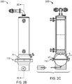
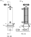
- FIGs. 1A-C , 2A-C , and 3A-C show isometric, front, and cross-sectional views of three different embodiments of disposable ATF housing and pump units 100, 200, and 300, respectively, as described herein.
- the housing, the diaphragm pump, the internal diaphragm, valves, filters, and other constituents of the new ATF housing and pump units can be constructed from materials that meet certain requirements.
- the materials must withstand the pressures generated during operation of typical fluid filtration systems, be free of toxins that can harm or kill cells or microorganisms, be readily molded into desired shapes, be light and relatively inexpensive, and must be able to be ethylene oxide (EO) or gamma radiation.
- EO ethylene oxide
- useful materials include polycarbonate (PC) (e.g., HPS grade from Sabic), polysulfone (PS), copolyesters of BPA-free plastics (e.g., TRITAN® from Eastman Chemical Co.), polypropylene (PP), nylon, glass-filled polymers, ultra-high-molecular-weight polyethylene (UHMWPE), polyether ether ketone (PEEK), and composites (e.g., glass/PC, glass/PS, and glass/nylon).
- PC polycarbonate
- PS polysulfone
- TRITAN® from Eastman Chemical Co.
- PP polypropylene
- nylon nylon
- glass-filled polymers e.g., ultra-high-molecular-weight polyethylene (UHMWPE), polyether ether ketone (PEEK), and composites
- UHMWPE ultra-high-molecular-weight polyethylene
- PEEK polyether ether ketone
- composites e.g., glass/PC, glass/
- FIGs. 1A-1C are views of an embodiment of a disposable ATF housing and pump unit 100 that includes a disposable clamp ring 110 and can be used in the ATF filtration system illustrated in FIG. 1C (described in further detail below).
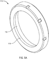
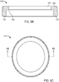
- permeate ports 102 are included at upper and lower ends of the filter housing 5 (as shown in FIG. 6A ) in addition to the entrance end 42 of filter housing 5 and air inlet port 23 shown in FIG. 6A .
- the clamp ring can be made of a rigid, machinable or moldable plastic, as described herein, e.g., acrylonitrile butadiene styrene (ABS), polyethylene (PE), PP, PC, PS, nylon, a glass-filled polymer, or a composite.
- ABS acrylonitrile butadiene styrene
- PE polyethylene
- PP polypropylene
- PC polypropylene
- PS polystyrene
- nylon e.g., polystyrene
- glass-filled polymer e.g., polystyrene (ABS), polyethylene (PE), PP, PC, PS, nylon, a glass-filled polymer, or a composite.
- FIGs. 2A-2C are views of a second embodiment of a disposable ATF housing and pump unit 200 that also includes the disposable clamp ring 110
- FIGS. 3A-3C are views of a third embodiment of a filter assembly 300 that also includes the clamp ring 110.
- the disposable clamp ring 110 of this disclosure can be used with a variety of filter assembly arrangements. Dimensions shown in the figures are intended to illustrate a specific example, and are not intended to be limiting.
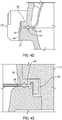
- FIGs. 4A-4E illustrates the bottom, ATF pump portion of the disposable ATF housing and pump units 100, 200, 300 shown in FIGs. 1C , 2C, and 2C , and which include the diaphragm pump 4 with disposable clamp ring 110, which is used to fix a diaphragm outer flange 47 of the flexible internal pump diaphragm 6, between liquid receiving chamber 7, and air side chamber 8 with a leak-proof connection.
- the top and bottom hemispheres of the ATF pump each include a flange 26 and 27, respectively between which the ATF pump diaphragm 6 is sandwiched when the two hemispheres are assembled.
- Flange 27 of the lower half of the ATF pump comprises an external threading to be used to engage the disposable clamp ring and compress both flanges across the diaphragm.
- Figure 4E shows the details of features added to aid in sealing across the diaphragm in larger diameter pump geometries.
- disposable clamp ring 110 is a cylindrical clamp that encloses and seals the internal diaphragm 6 between the peripheral flanges 26 and 27 of the two pump half chambers, by encircling the peripheral flanges 26 and 27 on their outer circumference, as well as a top portion of the flange 26.
- the outer radial contact surface 49 of at least the lower (in these embodiments) flange 27 is threaded, i.e., the radial circumference of the peripheral flange 27 has threads that contact and mate with threads on the lower inner surface 112 of the disposable clamp ring 110 at the radial contact surface 49.
- the other flange 26 may or may not include an external thread.
- Other embodiments show a two piece lock ring setup with a bottom ring that threads into a top ring internally or externally to compress across the flanges.
- peripheral flanges 26 and 27 work together with the disposable clamp ring to secure the diaphragm outer flange 47 between the upper and lower surfaces of flanges 26 and 27, respectively.
- the diaphragm pump peripheral flanges 26 and 27 are spaced from each other by a distance somewhat less than the corresponding thickness of internal diaphragm outer flange 47 such that when the two facing peripheral flanges 26 and 27 are forced together by screwing on disposable clamp ring 110, they compress to squeeze diaphragm outer flange 47 between the two peripheral flanges 26 and 27. In this design, 10-30% compression across the diaphragm is sufficient to seal both the air and liquid sides of the hemisphere.
- FIG. 4E additional features can be added to increase and/or decouple sealing and containing the diaphragm at high pressures ( FIG. 4E ).
- energy director protrusions 28 which are additional protrusions and/or grooves worked into one or both inner flanges to provide additional compression and/or sealing across the diaphragm.
- flanges 26 and 27 can contain a groove that is designed to accept a counterpart O-ring 44 portion or protrusion of the internal diaphragm 6. Once in contact, the periphery of peripheral flanges 26 and 27 can be sealed to each other along their contact surfaces of their opposing faces. In the process, internal diaphragm 6 is sealed securely between the two peripheral flanges 26 and 27.
- the new methods allow for setting the magnitude of the compression on internal diaphragm outer flange 47 by controlling the compression distance between corresponding and adjacent pump flange segments.
- a torque specification can be measured that correlates to sufficient compression of the diaphragm to contain pressure at several orders of safety in the design.
- the torque specification required to seal each ATF system is different. The larger the ATF system the larger the torque needed on the lock ring to compress the diaphragm. For example the ATF2 system 100 series, only requires 10-20 lbft while the ATF10 300 series requires 80+ lbft. An ATF system sized between these two examples would require between 20-90 lbft.
- disposable clamp ring 110 has an upper portion 120 and lower portion 122.
- the upper portion 120 has a smaller inner radius compared to the lower portion 122.
- the inner (e.g., radially closest to the centerline) surface of the lower portion 122 is referred to herein as lower inner surface 112, which is threaded and which engages with the radial perimeter outer surface of peripheral flange 27 of the ATF pump drive chamber 8.
- the inner surface of the upper portion 120 is upper inner surface 114, which is radially closer to the centerline compared to the lower inner surface 112.
- the upper inner surface 114 engages with an outer surface of the liquid receiving chamber 7.
- the liquid receiving chamber 7 is a hemisphere and thus has a curvature, rather than being a flat surface.
- the upper inner surface 114 is angled at an angle ⁇ to the horizontal.
- the angle ⁇ can be 0-5°, e.g., 1.0, 1.5, 2.0, 2.5, 3.0, 3.5, 4.0, or 4.5°, but is adjusted as required to accommodate the curvature of variously sized hemispheres of differently-sized ATF diaphragm pumps 4.
- This mating surface reinforces the upper hemisphere during high pressure conditions.
- the upper and lower hemispheres do not touch during assembly, they are forced together, but are separated by the compressed diaphragm.
- the new disposable ATF pumps can be used with enclosed filtration systems that employ a retentate chamber and a filtrate chamber, e.g., as shown in FIG. 6A and described in further detail below.
- enclosed filtration systems that employ a retentate chamber and a filtrate chamber, e.g., as shown in FIG. 6A and described in further detail below.
- Such ATF filtration systems and ATF pumps have been described in Shevitz, U.S. Pat. No. 6,544,424 .
- a convenient way to create a retentate chamber and filtrate chamber in the new disposable ATF pumps is to use a hollow fiber filter cartridge.
- a hollow fiber filter cartridge is made as a cartridge that comprises multiple hollow fibers (HF) that run in parallel along the length of the cartridge and are embedded at each end of the cartridge (preferably with a potting agent); the lumens at the end of the HFs are retained open, thus forming a continuous passage through each of the lumens from one end of the cartridge to the other, i.e., from a cartridge entrance end, to a cartridge exit end.
- the hollow fibers are enclosed by the outer wall of the cartridge (i.e., the cartridge wall) and a potting layer at their ends.
- the retentate chamber is extended beyond the internal spaces of the HFs by adapters that fit to each end of the cartridge.
- Each adapter in conjunction with an end of the cartridge defines a space that is part of the retentate chamber. Depending on the direction of fluid flow through the fibers, that space serves to either (1) collect fluid as it exits the fibers or (2) allow fluid arriving from an external source to interface with the HF open ends and distribute itself among those HFs for purposes of continuing its path towards the other end of the cartridge.
- Each adapter will have two ends, one end fitted to the cartridge and the other end with an opening connectable to a vessel or a pump.
- the vessel is connected to the adapter by a line that allows fluid flow but, if desired, the vessel can be connected directly to the adapter or the adapter may form part of the vessel where part or the entire content of the vessel may be contained within the adapter.
- the adapter is connected directly to the disposable ATF pump but, if desired, the pump can be connected to the pump via a line that permits fluid flow.
- the retentate chamber When a connecting line is added to an adapter, the retentate chamber is extended to also include the space inside that connecting line.
- a connecting line is connected at one end to an adapter and at its other end to a vessel (e.g., one that contains cells suspended in growth medium), one could consider the interior of the vessel to be a further extension of the retentate chamber, but for purposes of description and discussion herein the vessel and the retentate chamber are referred to as separate entities.
- the walls of the lumens of a hollow fiber filter are permeable, conveniently providing a barrier that is either fully permeable or selectively permeable.
- the selectively permeable hollow fiber walls may range in selectivity that ranges the entire gamut of membrane pore sizes, commonly classified as osmotic membranes, and from ultrafiltration microfiltration to macrofiltration and also micro-carrier filtration, where, for example,), the pore size range is about 10-500 kDa and 0.2-100 micron. Pore sizes of about 0.2 micron are commonly used for retaining cells and allowing metabolites and other molecules or molecular complexes to pass throughout the pores.
- ultrafiltration pore sizes in the range 10 kDa to 500 kDa are preferred for retaining not only the cells, but molecules and molecular complexes, e.g., produced by the cells, that are larger than the pore sizes.
- Macrofiltration membranes range from 7 to 100 um and are used to retain microcarriers or larger cells. These selectively permeable hollow fibers must be wet with a liquid compatible with the fluid substance be filtered. For example in cell culture the membrane must be wet with water based solutions that are compatible with cell culture growth. Many membranes require alcohol containing solutions to initially wet the pores and achieve flux rates during operation that are needed to perform the filtration process.
- FIG. 6B shows the ports and fluid bags that can be used to add fluid to the ATF device.
- Flushing with serum free media in a sterile environment can then be performed using the alternating pumping action of the ATF device. Then the flush fluid can be drained from the port and the device is ready to operate in the cell culture process while maintaining a sterile environment.
- the filter cartridge can include an outer wall that constitutes a barrier that may be non-selective (fully permeable), but is preferably semi-permeable, (not allowing dissolved matter (e.g., molecules and molecular complexes) larger than the pore sizes in the barrier to pass through the barrier and not allowing particulate matter larger than the pore sizes to pass through the barrier).
- a barrier that may be non-selective (fully permeable), but is preferably semi-permeable, (not allowing dissolved matter (e.g., molecules and molecular complexes) larger than the pore sizes in the barrier to pass through the barrier and not allowing particulate matter larger than the pore sizes to pass through the barrier).
- Pore sizes in the range 10 kDa to 500 kDa are preferred for retaining only molecules and molecular complexes larger than the pore sizes.
- the pore sizes can be made small enough or large enough, so that, respectively, the barrier is highly restrictive, allowing only small salts and their components to pass through or allowing molecules or particles larger than 500 kDa to pass through the membrane.
- Such membrane selectivity is not only restricted to pore size but to other membrane properties, including: charge, hydrophobicity, membrane configuration, membrane surface, pore polarity, etc.
- the steps generally include:
- the process includes the steps of:
- FIG. 6A shows an enclosed fluid filtration system 1 connected via a fluid connector 3 to a process or cell culture vessel 2 that contains the fluid material or retentate 9 to be processed.
- the fluid filtration system 1 contains at least two chambers: a retentate chamber 45 confining the unfiltered material on the inside of the fiber lumens and a filtrate chamber 10 within the filter housing 5.
- the fluid filtration system 1 is the new disposable ATF housing and pump units. In general these units are enclosed by filter housing 5, whose shape, size or orientation may be varied as needed to enclose the system.
- the filter housing 5 may be constructed from a variety of materials, including solid polymers, such as polycarbonate or polysulfone, flexible or elastic materials, glass-filled polymers, or any other materials or composites of materials that meet the requirements of strength, non-toxicity, and sterilizability as described herein.
- the fluid filtration system is connected to a process or cell culturing vessel 2 via a fluid connector conduit 3.
- the process vessel 2 may be any suitable container for a fluid to be processed.
- it may be a bioreactor, a circulatory system (e.g., for a human or animal patient or subject) or any other vessel, nonexclusively including tanks, bags, flasks and the like, which can contain liquids.
- the process vessel 2 may be composed of any suitable material or combination of materials, including, synthetic polymers, inert metals, such as stainless steel, glass, etc.; nor shall they exclude rigid, flexible or elastic materials or a combination thereof; nor should such materials be limited in shape, size or configuration, as long as they result in a process vessel.
- the process vessel 2 is not limited as to accessibility: it may be modified to allow additions to or subtractions from the content of the vessel.
- Lines or tubes 36 and 39 can be used to effect additions to or subtractions from the content of process vessel 2, for example using a pump 14 to control such addition or subtractions.
- Such process vessels are commercially available in all sizes and configurations, and are well known to those in the field.
- the fluid connector 3 serves to direct a fluid from the process vessel 2 via fluid exchange port 35 to the entrance end 42 of filter element 11 which also corresponds to the entrance end of the retentate chamber 45.
- Entrance end 42 while serving as an entrance to retentate chamber 45, may also serve as a reservoir for retentate; its shape and positioning may be varied according to need; its volume may be approximately equal to or less than the diaphragm pump displacement volume, facilitating between entrance end 42 (reservoir) and pump, and further facilitating greater level of retentate concentration and recovery of final concentrate.
- the fluid flow is further directed through the filter channels 17, which would correspond to the interiors of the lumen(s) of a hollow fiber filter should filter element 11 correspond to a hollow fiber filter.
- the filter channels collectively correspond to the retentate chamber 45 of the fluid filtration system 1.
- the fluid flow proceeds to, and exits from, the exit end 43 of the filter element 11.
- the exit end 43 of both the filter element 11 and the retentate chamber 45 connects directly to a liquid receiving chamber 7 of a diaphragm pump 4.
- the filter exit end 43 may be connected to the diaphragm pump 4 through a conduit (not shown here).
- the ATF diaphragm pump 4 as described herein generates the flow through the filter element 11 between process vessel 2 and back to the pump.
- the ATF diaphragm pump 4 preferably comprises a pump housing separated into a drive chamber 8 (the first interior chamber) and the liquid receiving chamber 7 (the second interior chamber), by an internal diaphragm 6.
- the pump housing is made of two housing components, the first pump housing component 25 and the second pump housing component 24.
- the components comprise peripheral flanges 26 and 27, respectively.
- Pressure in the drive chamber 8 drives the diaphragm within diaphragm pump 4 without causing contamination of the fluid content in the liquid receiving chamber 7.
- the pump can be an air driven pump. Compressed air is directed by controller 54 to drive chamber 8 through line (tube) 21, preferably through a sterilizing filter 22 and an air inlet port 23. Increasing the air pressure in drive chamber 8 relative to process vessel 2 drives a flexible internal diaphragm 6 into liquid receiving chamber 7, driving liquid in that chamber through the filter element 11 to vessel 2. The reverse flow from process vessel 2 to diaphragm pump 4 is generated by reducing the pressure in drive chamber 8 relative to the vessel 2. The cycles are repeated. Alternating flow generated by such a pump has been described in U.S. Pat. No. 6,544,424 .
- the filter element 11 is a made as a cartridge that comprises multiple hollow fibers (HF) that run, in parallel, the length of the cartridge, from a cartridge entrance end to a cartridge exit end.
- a segment of the hollow fibers are externally potted at both ends of the cartridge, by methods common to manufacturers of hollow fiber cartridges; the hollow fibers are enclosed by a perforated wall 19 which is then sealed to an outer housing via O-rings or other means. Examples of potting compounds are epoxies and polyurethanes.
- the intra-luminar spaces are considered collectively to constitute a retentate chamber in each of the present systems.
- the fiber membranes can be potted directly into the outer filter housing 5.
- the harvest from system 1 is collected via line 13 which is connected to harvest port 12, which allows fluid flow from the filter housing 5 and that line so as to allow fluid to leave the system 1 via pump 14.
- the filter channels 17 corresponding to the walls of the lumens (hollow fibers) of the illustrated hollow fiber filter are selectively-permeable, conveniently providing the selectively permeable wall referred to in the descriptions of the systems.
- the outer wall 19 of the filter cartridge (the cartridge wall) is perforated to allow fluid flow to harvest port 12.
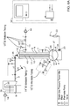
- the pump hemisphere test apparatus 55 design is shown in FIG. 7 .
- the design differed from a stainless steel standard pump in regards to the methods used to hold the silicone pump diaphragm in compression.
- a flat flange outside of the silicone diaphragm on either half of the pump was added so that these could be secured together using various methods of attachment, and a small "shelf' feature was included on one pump half to prevent over-compression.
- the assembly also had holes to allow the attachment of a large steel eye-hook and a steel tie-down hook to enable failure testing with an Instron® machine (for strength analysis of the different attachment methods).
- Example 2 Preparation of a Disposable ATF Device Using Serum Free Media as a Flushing Solution and Operation of the ATF Device to Attain Membrane Wetting
- the following is a procedure designed to flush a hollow fiber membrane quickly and efficiently using ATF technology.
- This flushing benefits the user by wetting, conditioning, lowering endotoxin, and removing total organic compounds (TOC) from the membrane with one method.
- TOC total organic compounds
- Using the ATF is advantageous over other methods as it requires less volume and can be performed with ease within a closed sterile system without using solutions not compatible with cell culture growth.
- ATF run rates for various size disposable ATF devices is provided.
- Retentate fluid can be left in device if same as bioreactor media or can be drained from port 401 and refilled with media from the bioreactor prior to cell culture production operation.
- Example 3 Using a Conditioned ATF Disposable Device for Filter Integrity Testing
- a filter integrity test is a means to insure that the hollow fiber membranes are intact and the membrane pores are fully wetted. After flushing in ATF mode, drain the wetting fluid (media) back into the wetting fluid bag via gravity or by reversing Pump P2 with air source open to 1-2 psi to raise the diaphragm and all other valves open. The bag should be positioned to allow draining.
- a disposable ATF6 with a 0.2 ⁇ m Spectrum PES filter was connected to a Repligen C410 controller.
- the A2B connection was connected to a water bath at 40°C and ran for 500,000 Pressure and 500,000 Exhaust cycles at an ATF Rate of 17.2 liters per minute (LPM).
- Permeate was pulled at 5.7 LMH as it would be used in a perfusion process to keep the operation as similar to a bioreactor condition as possible. This leads to approximately 10,000 Pressure and 10,000 Exhaust cycles per day.
- the ATF ran for 50 days while monitoring diaphragm displacement volume. The displacement volume remained constant throughout the entirety of the 50 day run maintaining a constant flow rate as expected.
- FIGs. 8 and 9 Cells cultured using the ATF filters of this disclosure were tested, and results are shown in FIGs. 8 and 9 .
- a gamma irradiated sterile suATF2 filter (0.2 ⁇ m polyethersulfone microfilter with 0.13 m 2 surface area) was tested in a monoclonal antibody-producing CHO cell perfusion process. After gamma sterilization process, the suATF2 filter was connected to a 5.0 L bench scale bioreactor (at 1.5 L working volume) using sterile GE Ready mate® connectors. A C24Uv2.5 ATF controller was used to operate the suATF2 filter.
- the suATF2 filter Prior to inoculation, the suATF2 filter was flushed with 1.5 L of CD optiCHO® growth medium (Thermo Fisher) contained in the bioreactor for 1 hour at an ATF rate of 0.9 LPM with a permeate rate of 12.4 LPM (flux 5.7 LMH) recirculating in the bioreactor.
- the filter was flushed with media to wet the filter and to reduce endotoxin levels below 0.25 EU/mL.
- ATF pump was stopped temporarily and the flushed media was discarded from the bioreactor and the suATF2 filter in a sterile manner.
- A2B (ATF to Bioreactor) connection was clamped and 1.5 L of fresh CD optiCHO® growth media (Thermo Fisher) supplemented with 4 mM GlutaMAX® (Thermo Fisher) and 100 ng/mL LONG®R 3 IGF-I (Repligen) were added to the bioreactor.
- CHO DP-12 clone#1934 LR3 adapted cells from ATCC, expressing recombinant human anti-IL-8) were inoculated at a seeding density of 5.5E5 cells/mL.
- the bioreactor was maintained at 37°C. pH was controlled at 7.2 ⁇ 0.4 dead band until day 4 than controlled at 6.8 ⁇ 0.1 dead band using 0.1N NaOH and CO 2 . DO was maintained at 40% using pure oxygen either by an L-sparger or a micron sparger. Air was continuously sparged using an L-sparger for aeration and for stripping of CO 2 . Antifoam C and glucose feed were added as needed to control foaming and to maintain glucose level above 1g/L. The bioreactor was run on batch mode until day 4 and perfusion was initiated on day 4 at 1 volume vessels per day or VVD (1.5 L/day perfusion rate).
- Perfusion rate was manually increased stepwise to 2 VVD (3 L/day) on day 5 and 2.5 VVD (3.75 L/day) on day 6 until the end of perfusion run.
- the ATF2 perfusion bioreactor data shown below is from day 0 to day 10 (bioreactor process is still ongoing).
- FIG. 8 Resulting viable cell concentration and percent viability over days is shown in FIG. 8 (in solid and open squares, respectively). Protein concentration profile for the harvest line and total protein concentration over days is shown in FIG. 9 .
Claims (14)
- Unité à flux tangentiel alternatif (ATF, alternating tangential flow) jetable comprenant :un tube creux en plastique rigide non toxique stérilisable,un premier hémisphère de pompe fixé à une extrémité du tube creux, ledit premier hémisphère de pompe comprenant une première bride circonférentielle (26), une ouverture présente dans le premier hémisphère de pompe permettant le passage d'un fluide entre le premier hémisphère de pompe et le tube creux,un deuxième hémisphère de pompe comprenant une deuxième bride circonférentielle (27) conçue pour se coupler à la première bride circonférentielle (26), etun diaphragme souple conçu pour être agencé entre les première et deuxième brides circonférentielles (26, 27) ;caractérisé en ce que soit la première bride circonférentielle (26) soit la deuxième bride circonférentielle (27) présente un filetage externe, eten ce qu'une bague de serrage (110) possède une surface interne (112) présentant un filetage interne, ladite bague de serrage (110) étant conçue pour pouvoir être placée sur l'hémisphère de pompe dont la bride circonférentielle n'est pas filetée et pour être fixée à la bride circonférentielle filetée (26, 27).
- Unité ATF jetable selon la revendication 1, dans laquelle la bague de serrage (110) comprend une ou plusieurs matières plastiques parmi l'acrylonitrile butadiène styrène, le polyéthylène, le polyéthylène, le polycarbonate et le polysulfone.
- Unité ATF jetable selon la revendication 1 ou la revendication 2, dans laquelle la bague de serrage (110) comprend une partie inférieure présentant les filets internes et une partie supérieure (114) présentant une surface interne conçue pour recevoir une surface externe incurvée ou coudée du premier hémisphère de pompe.
- Unité ATF jetable selon l'une quelconque des revendications 1 à 3, comprenant en outre un ou plusieurs orifices (23, 35, 102) permettant le montage d'un ou plusieurs éléments parmi un réservoir d'air, un sac de rinçage de perméat et un sac d'apport de fluide au moyen de raccords stériles afin de produire un système fermé apte à fonctionner en ATF et de mouiller le filtre membranaire.
- Unité ATF jetable selon l'une quelconque des revendications 1 à 4, dans laquelle l'unité ATF a une structure susceptible de résister à une pression allant jusqu'à 3,1 MPa (450 psi) sans se rompre ni fuir.
- Unité ATF jetable selon l'une quelconque des revendications 1 à 5, dans laquelle les première et deuxième brides présentent une rainure conçue pour se coupler à un renflement (28) présent sur le diaphragme souple.
- Unité ATF jetable selon l'une quelconque des revendications 1 à 6, dans laquelle la bague de serrage est conçue pour comprimer le diaphragme souple entre les première et deuxième brides.
- Unité ATF jetable selon la revendication 7, dans laquelle le niveau de compression peut être modifié en appliquant des spécifications de serrage se traduisant par une compression suffisante du diaphragme pour contenir la pression à différents niveaux de sécurité dans sa conception.
- Unité ATF jetable selon la revendication 8, dans laquelle les spécifications de serrage vont d'environ 13,6 à 136 Nm (d'environ 10 à environ 100 lbft), par exemple, lesdites spécifications de serrage allant d'environ 40,7 à environ 95 Nm (d'environ 30 à environ 70 lbft) et les spécifications de serrage étant éventuellement supérieures à 108 Nm (80 lbft).
- Unité ATF jetable selon l'une quelconque des revendications 1 à 9, comprenant en outre des éléments favorisant l'étanchéité entre les premier et deuxième hémisphères afin d'assurer l'étanchéité sur tout le diaphragme.
- Unité ATF jetable selon la revendication 10, dans laquelle les éléments favorisant l'étanchéité comprennent des éléments directeurs d'énergie ou des surfaces en relief.
- Procédé de préparation d'un dispositif de filtration jetable totalement mouillé, le procédé comprenant :le montage de sacs de fluide de rétentat et de perméat à des orifices supérieurs d'une unité à flux tangentiel alternatif (ATF, alternating tangential flow) jetable selon l'une quelconque des revendications 1 à 11 au moyen de raccords stériles,la fixation d'un sac contenant un milieu ou autre fluide à un orifice d'entrée de pompe, etla mise en fonctionnement de l'unité ATF jetable pour réaliser un flux du milieu ou autre fluide à travers un filtre membranaire à l'intérieur du tube creux de l'unité ATF jetable.
- Procédé selon la revendication 12, comprenant en outre la vidange du fluide de rétentat de l'unité ATF jetable par l'orifice d'entrée de pompe après la mise en fonctionnement de l'unité ATF jetable pour réaliser un flux de fluide afin d'entraîner une perméation d'une chambre présente au sein du tube creux de l'unité ATF jetable.
- Procédé d'utilisation d'un dispositif de filtration jetable, le procédé comprenant :la réalisation d'une unité à flux tangentiel alternatif (ATF, alternating tangential flow) jetable selon l'une quelconque des revendications 1 à 11,la disposition de l'unité ATF dans un circuit fluidique par montage de sacs de fluide sur des orifices supérieurs de l'unité ATF au moyen de raccords stériles, et la fixation d'un réservoir de fluide à un orifice d'entrée de pompe de façon que l'unité ATF produise un flux de milieu ou autre fluide à filtrer à travers un filtre membranaire à l'intérieur du tube creux de l'unité ATF jetable, etla mise au rebut de l'unité ATF une fois la filtration terminée.
Priority Applications (1)
| Application Number | Priority Date | Filing Date | Title |
|---|---|---|---|
| EP20172773.2A EP3708835A1 (fr) | 2015-11-10 | 2016-08-26 | Unités de filtration jetables à flux tangentiel alternatif |
Applications Claiming Priority (2)
| Application Number | Priority Date | Filing Date | Title |
|---|---|---|---|
| US201562253513P | 2015-11-10 | 2015-11-10 | |
| PCT/US2016/049096 WO2017082990A1 (fr) | 2015-11-10 | 2016-08-26 | Unités de filtration jetables à flux tangentiel alternatif |
Related Child Applications (1)
| Application Number | Title | Priority Date | Filing Date |
|---|---|---|---|
| EP20172773.2A Division EP3708835A1 (fr) | 2015-11-10 | 2016-08-26 | Unités de filtration jetables à flux tangentiel alternatif |
Publications (3)
| Publication Number | Publication Date |
|---|---|
| EP3374636A1 EP3374636A1 (fr) | 2018-09-19 |
| EP3374636A4 EP3374636A4 (fr) | 2018-11-14 |
| EP3374636B1 true EP3374636B1 (fr) | 2020-06-03 |
Family
ID=58694975
Family Applications (2)
| Application Number | Title | Priority Date | Filing Date |
|---|---|---|---|
| EP16864714.7A Active EP3374636B1 (fr) | 2015-11-10 | 2016-08-26 | Unités de filtration jetables à flux tangentiel alternatif |
| EP20172773.2A Pending EP3708835A1 (fr) | 2015-11-10 | 2016-08-26 | Unités de filtration jetables à flux tangentiel alternatif |
Family Applications After (1)
| Application Number | Title | Priority Date | Filing Date |
|---|---|---|---|
| EP20172773.2A Pending EP3708835A1 (fr) | 2015-11-10 | 2016-08-26 | Unités de filtration jetables à flux tangentiel alternatif |
Country Status (6)
| Country | Link |
|---|---|
| US (2) | US11156219B2 (fr) |
| EP (2) | EP3374636B1 (fr) |
| JP (2) | JP7039477B2 (fr) |
| KR (1) | KR102613876B1 (fr) |
| CN (1) | CN108368839B (fr) |
| WO (1) | WO2017082990A1 (fr) |
Families Citing this family (21)
| Publication number | Priority date | Publication date | Assignee | Title |
|---|---|---|---|---|
| JP7102391B2 (ja) | 2016-07-25 | 2022-07-19 | レプリゲン・コーポレイション | 交互タンジェンシャルフローによる高速収穫 |
| USD868114S1 (en) * | 2016-10-21 | 2019-11-26 | Performance Pulsation Control, Inc. | Combination gas pulsation dampener, cross and strainer |
| US10508763B2 (en) * | 2016-11-09 | 2019-12-17 | Performance Pulsation Control, Inc. | Combination gas pulsation dampener, cross and strainer |
| CN111263631A (zh) | 2017-10-26 | 2020-06-09 | 瑞普利金公司 | 微型交替切向流灌注过滤器、处理容器及其使用方法 |
| DE102017127017A1 (de) * | 2017-11-16 | 2019-05-16 | Sartorius Stedim Biotech Gmbh | Automatisierte Einweg-Filtrationsvorrichtung und Verfahren zur Steuerung einer automatisierten Einweg-Filtrationsvorrichtung |
| US10799816B2 (en) * | 2017-12-28 | 2020-10-13 | Repligen Corporation | Plunger pumping arrangement for a hollow fiber filter |
| CN111565823B (zh) * | 2018-01-12 | 2023-03-31 | 富默乐有限公司 | 切向流过滤tff系统和包括集成泵装置的一次性tff单元 |
| EP3874023A4 (fr) * | 2018-11-02 | 2022-08-17 | Wuxi Biologics Ireland Limited | Procédé de culture cellulaire par perfusion intensifiée avec récolte continue et sans purge cellulaire |
| US11680239B2 (en) | 2018-12-31 | 2023-06-20 | Repligen Corporation | Filter for mammalian cell culture perfusion and clarification with hydrophobic hollow fiber |
| US20220088538A1 (en) * | 2019-01-10 | 2022-03-24 | Repligen Corporation | Hollow fiber filtration systems and methods |
| GB201901995D0 (en) * | 2019-02-13 | 2019-04-03 | Nicoventures Trading Ltd | Container for aerosolisable material |
| CN110066007B (zh) * | 2019-04-30 | 2022-02-01 | 广州细润环保科技有限公司 | 过滤单元、膜堆反应器、柱式反应器及其制造方法 |
| JP2022532831A (ja) * | 2019-05-21 | 2022-07-20 | レプリゲン・コーポレーション | 交互接線流ポンピング方法 |
| CN114340756A (zh) * | 2019-08-05 | 2022-04-12 | 瑞普利金公司 | 用于利用交替的切向流的连续处理的装置、系统和方法 |
| EP4073228A4 (fr) * | 2019-12-13 | 2023-05-31 | Repligen Corporation | Bioréacteur à flux tangentiel alternatif avec système à fibres creuses et procédé d'utilisation |
| FR3105023B1 (fr) * | 2019-12-20 | 2022-06-03 | Abc Transfer | Conteneur etanche pourvu d’une bride bi-matiere |
| JP7394672B2 (ja) * | 2020-03-19 | 2023-12-08 | テルモ株式会社 | 透析用カセット及びそのポンプ |
| CN111534411A (zh) * | 2020-04-03 | 2020-08-14 | 利穗科技(苏州)有限公司 | 一种交替切向流罐装培养装置及其控制方法 |
| CN116529354A (zh) * | 2020-12-15 | 2023-08-01 | 环球生命科技咨询美国有限责任公司 | 用于使用加压验证生物处理系统的完整性的系统和方法 |
| US11925831B2 (en) * | 2021-01-28 | 2024-03-12 | Lloyd Johnson, III | Arm exercise attachment |
| CN114713037B (zh) * | 2022-06-10 | 2022-09-20 | 北京先通国际医药科技股份有限公司 | 在线滤膜完整性测试装置及方法、及其用途 |
Family Cites Families (77)
| Publication number | Priority date | Publication date | Assignee | Title |
|---|---|---|---|---|
| USRE26127E (en) * | 1966-12-13 | Sealing closure | ||
| US2317073A (en) * | 1941-09-10 | 1943-04-20 | Martin Decker Corp | High pressure diaphragm unit for fluid pressure gauges |
| US2563257A (en) * | 1946-09-16 | 1951-08-07 | Ernest W Loukonen | Pulsation absorber |
| US2697451A (en) * | 1953-10-02 | 1954-12-21 | Walter T Knauth | Alleviator |
| US2751084A (en) | 1954-03-11 | 1956-06-19 | Purolator Products Inc | Fuel tank filter installation |
| US2851059A (en) * | 1954-05-26 | 1958-09-09 | Inv Aeronatiques Et Mecaniques | Accumulator |
| NL136034C (fr) | 1965-12-22 | |||
| US3547560A (en) * | 1969-03-05 | 1970-12-15 | Economics Lab | Injector pump apparatus |
| CH525388A (it) * | 1970-06-19 | 1972-07-15 | Oliverio Biagio | Pompa idraulica per irrorare del liquido funzionante mediante la pressione dell'acqua esistente nella rete stradale |
| US3825154A (en) * | 1972-01-17 | 1974-07-23 | W Jaeger | Fluid dispensing system |
| FR2300292A1 (fr) * | 1975-02-05 | 1976-09-03 | Eaton Williams Raymond | Chaudiere a electrodes |
| JPS54123584A (en) | 1978-03-20 | 1979-09-25 | Kuraray Co Ltd | New treating apparatus for fluid and method thereof |
| DE7831128U1 (de) | 1978-10-19 | 1979-02-15 | Boll & Kirch Filterbau Gmbh, 5000 Koeln | Rueckspuelfilter |
| US4219125A (en) * | 1978-12-07 | 1980-08-26 | Structural Fibers, Inc. | Tank closure assembly |
| US4267940A (en) * | 1979-06-26 | 1981-05-19 | Purex Corporation | Removable clamp structure for tank sections which at times block said removal |
| US4290347A (en) * | 1979-10-01 | 1981-09-22 | Acf Industries, Inc. | Crashworthy fuel pump |
| US4334838A (en) * | 1980-01-29 | 1982-06-15 | The Coca-Cola Company | Diaphragm type fluid pump having a flexible diaphragm with an internal reinforcing plate |
| JPS57152477U (fr) * | 1981-03-20 | 1982-09-24 | ||
| JPS601404A (ja) | 1983-06-16 | 1985-01-07 | Matsushita Electric Ind Co Ltd | シリンダ−駆動方法 |
| US5286646A (en) | 1985-11-25 | 1994-02-15 | Boehringer Mannheim Gmbh | Method for mammalian cell culture |
| US4806484A (en) | 1987-08-07 | 1989-02-21 | Igb Products, Ltd. | Perfusion airlift bioreactor |
| JPS6467206A (en) | 1987-09-07 | 1989-03-13 | Jgc Corp | Element for filtering and desalting apparatus |
| JPH0167206U (fr) | 1987-10-23 | 1989-04-28 | ||
| US4844804A (en) | 1988-03-18 | 1989-07-04 | Separation Dynamics, Inc. | Fluid decontamination system |
| AU611072B2 (en) * | 1988-12-29 | 1991-05-30 | Chang, Ann Lois | Diaphragm pump |
| DE3937613A1 (de) * | 1989-10-26 | 1991-05-02 | Schuetz Werke Gmbh Co Kg | Kunststoffdeckel fuer blasgeformte kunststoffaesser |
| US5106501A (en) | 1990-01-16 | 1992-04-21 | Ametek, Inc. | Multi-function filter cartridge with flow distribution control |
| US5055198A (en) | 1990-03-07 | 1991-10-08 | Shettigar U Ramakrishna | Autologous blood recovery membrane system and method |
| CN1057786A (zh) | 1990-07-06 | 1992-01-15 | 张任谦 | 隔膜泵 |
| US5128037A (en) * | 1990-12-27 | 1992-07-07 | Millipore Corporation | Spiral wound filtration membrane cartridge |
| US5303599A (en) * | 1992-07-29 | 1994-04-19 | Welker Engineering Company | Miniaturized sampler |
| US5411162A (en) * | 1992-07-31 | 1995-05-02 | Allen-Bradley Company, Inc. | V-band coupling for an explosion-proof enclosure |
| US5554293A (en) * | 1993-06-28 | 1996-09-10 | C. R. Bard, Inc. | Disposable blood washing and apheresis device and method of using thereof |
| JP3317753B2 (ja) | 1993-08-06 | 2002-08-26 | ダイセル化学工業株式会社 | 膜分離装置及び膜モジュール |
| US5563068A (en) | 1994-04-21 | 1996-10-08 | Genetic Therapy, Inc. | Bioreactor |
| JP3795101B2 (ja) | 1994-06-24 | 2006-07-12 | サッポロビール株式会社 | 濾過装置及びその原液回収方法 |
| JP3479373B2 (ja) | 1995-02-07 | 2003-12-15 | ダイセン・メンブレン・システムズ株式会社 | 中空糸型膜モジュール |
| US5712154A (en) | 1995-06-07 | 1998-01-27 | W.R. Grace & Co.-Conn. | Dual fiber bioreactor |
| JP4804599B2 (ja) | 1996-12-20 | 2011-11-02 | シーメンス・ウォーター・テクノロジーズ・コーポレイション | 洗浄方法 |
| SE508749C2 (sv) * | 1996-12-20 | 1998-11-02 | Lindab Ab | Sätt att hopkoppla två rör |
| US5811259A (en) | 1997-07-29 | 1998-09-22 | Ecomat, Inc. | Biochemical reactor |
| DE19734588A1 (de) | 1997-08-09 | 1999-02-11 | Boll & Kirch Filter | Rückspülfilter |
| US6051131A (en) | 1998-09-30 | 2000-04-18 | United States Filter Corporation | Flow modifier for submerged intake screen |
| US6139727A (en) | 1999-03-02 | 2000-10-31 | Anthony Mfg. Corp. | Self-cleaning water filter |
| US6569329B1 (en) | 1999-05-06 | 2003-05-27 | Innova Pure Water Inc. | Personal water filter bottle system |
| US7244357B2 (en) * | 1999-05-25 | 2007-07-17 | Miox Corporation | Pumps for filtration systems |
| US6295918B1 (en) * | 1999-10-15 | 2001-10-02 | John M. Simmons | Suspended diaphragm |
| NL1013465C2 (nl) | 1999-11-02 | 2001-05-03 | Stork Friesland Bv | Membraanfiltratie-element met hulselement en moforganen. |
| US6325932B1 (en) * | 1999-11-30 | 2001-12-04 | Mykrolis Corporation | Apparatus and method for pumping high viscosity fluid |
| US6544424B1 (en) | 1999-12-03 | 2003-04-08 | Refined Technology Company | Fluid filtration system |
| US6755894B2 (en) | 2001-05-02 | 2004-06-29 | Praxair Technology, Inc. | Hollow fiber membrane gas separation cartridge and gas purification assembly |
| CA2351272C (fr) | 2001-06-22 | 2009-09-15 | Petro Sep International Ltd. | Appareil de separation de fluides assiste par une membrane et methode |
| JP3542990B2 (ja) * | 2001-12-05 | 2004-07-14 | 株式会社ヤマダコーポレーション | ダイヤフラムポンプ装置 |
| US7285209B2 (en) | 2001-12-28 | 2007-10-23 | Guanghua Yu | Method and apparatus for separating emulsified water from hydrocarbons |
| US6764598B2 (en) | 2001-12-28 | 2004-07-20 | Filtration Solutions, Inc. | Method and apparatus for separating emulsified water from fuel |
| EP1490155B1 (fr) | 2002-03-18 | 2005-10-12 | Parker Hannifin Corporation | Filtre dans le reservoir pour applications hydrauliques mobiles, et ensemble correspondant |
| US7121423B2 (en) * | 2002-11-14 | 2006-10-17 | Sanders Stan A | Ovoid flexible pressure vessel, apparatus and method for making same |
| EP1466657B1 (fr) | 2003-04-11 | 2012-10-03 | Gambro Lundia AB | Dispositif de filtration avec plus d'une chambre à filtration |
| JP4547350B2 (ja) * | 2006-04-13 | 2010-09-22 | 東レエンジニアリング株式会社 | ピストンとそのピストンの製造方法及びそのピストンを備えたポンプ |
| US20140199193A1 (en) * | 2007-02-27 | 2014-07-17 | Deka Products Limited Partnership | Blood treatment systems and methods |
| US20080058697A1 (en) | 2006-04-14 | 2008-03-06 | Deka Products Limited Partnership | Heat exchange systems, devices and methods |
| WO2008026079A2 (fr) | 2006-07-21 | 2008-03-06 | Saxonia Bio Tec Gmbh | procédé et appareil associés aux systèmes de filtration de liquideS |
| JP2008082728A (ja) | 2006-09-26 | 2008-04-10 | Toray Ind Inc | 生体成分分画方法および分画装置 |
| US8888470B2 (en) | 2007-02-27 | 2014-11-18 | Deka Products Limited Partnership | Pumping cassette |
| WO2008122083A1 (fr) | 2007-04-04 | 2008-10-16 | Siemens Water Technologies Corp. | Protection de module membranaire |
| WO2009002780A1 (fr) | 2007-06-27 | 2008-12-31 | Ge Healthcare Bio-Sciences Corp. | Système et procédé pour assembler une structure de chromatographie à grande échelle |
| EP2257890B1 (fr) | 2008-03-27 | 2019-12-11 | Global Life Sciences Solutions USA LLC | Système rfid stérilisable aux rayons gamma pouvant empêcher une exploitation non autorisée de composants de bioprocédé associés |
| FR2930602A1 (fr) * | 2008-04-28 | 2009-10-30 | Gatech Sarl | Pompe hydraulique a raccord a rotule spherique |
| JP2010051910A (ja) | 2008-08-29 | 2010-03-11 | Parker Engineering Kk | フィルタープレスの異常検知方法及びフィルタープレス |
| JP2012503540A (ja) * | 2008-09-24 | 2012-02-09 | シェビッツ、ジェリー | 交互流濾過用スクリーンフィルタモジュール |
| JP5369037B2 (ja) * | 2010-03-29 | 2013-12-18 | Nok株式会社 | ダイアフラム |
| US9446354B2 (en) * | 2010-08-25 | 2016-09-20 | Repligen Corporation | Device, system and process for modification or concentration of cell-depleted fluid |
| WO2012026978A2 (fr) | 2010-08-25 | 2012-03-01 | Jerry Shevitz | Systèmes de filtration de fluide |
| EP2900804B1 (fr) * | 2012-09-27 | 2019-09-18 | GE Healthcare Bio-Sciences AB | Système de perfusion à écoulement tangentiel |
| CA3111230A1 (fr) * | 2013-03-15 | 2014-09-18 | Deka Products Limited Partnership | Systeme pour controler l'ecoulement dans une pompe sanguine |
| JP6398146B2 (ja) * | 2013-09-09 | 2018-10-03 | 澁谷工業株式会社 | 血液透析装置 |
| CN104117226B (zh) | 2014-07-04 | 2016-06-15 | 大连大学 | 分段式高效装柱可调节柱温可自由分拆的柱层析组合装置 |
-
2016
- 2016-08-26 US US15/772,761 patent/US11156219B2/en active Active
- 2016-08-26 KR KR1020187016282A patent/KR102613876B1/ko active IP Right Grant
- 2016-08-26 CN CN201680065697.8A patent/CN108368839B/zh active Active
- 2016-08-26 JP JP2018544023A patent/JP7039477B2/ja active Active
- 2016-08-26 EP EP16864714.7A patent/EP3374636B1/fr active Active
- 2016-08-26 WO PCT/US2016/049096 patent/WO2017082990A1/fr active Application Filing
- 2016-08-26 EP EP20172773.2A patent/EP3708835A1/fr active Pending
-
2021
- 2021-09-23 US US17/482,802 patent/US20230093783A9/en not_active Abandoned
-
2022
- 2022-03-09 JP JP2022036127A patent/JP7362812B2/ja active Active
Non-Patent Citations (1)
| Title |
|---|
| None * |
Also Published As
| Publication number | Publication date |
|---|---|
| JP2022084727A (ja) | 2022-06-07 |
| EP3708835A1 (fr) | 2020-09-16 |
| JP2019501772A (ja) | 2019-01-24 |
| EP3374636A1 (fr) | 2018-09-19 |
| JP7039477B2 (ja) | 2022-03-22 |
| EP3374636A4 (fr) | 2018-11-14 |
| CN108368839B (zh) | 2020-01-07 |
| JP7362812B2 (ja) | 2023-10-17 |
| KR20180082520A (ko) | 2018-07-18 |
| US20230093783A9 (en) | 2023-03-23 |
| KR102613876B1 (ko) | 2023-12-15 |
| US20180238317A1 (en) | 2018-08-23 |
| CN108368839A (zh) | 2018-08-03 |
| US11156219B2 (en) | 2021-10-26 |
| US20220008803A1 (en) | 2022-01-13 |
| WO2017082990A1 (fr) | 2017-05-18 |
Similar Documents
| Publication | Publication Date | Title |
|---|---|---|
| US20220008803A1 (en) | Disposable Alternating Tangential Flow Filtration Units | |
| US11225637B2 (en) | Enclosed filtration system processes | |
| JP6164487B2 (ja) | 流体濾過システム | |
| US6544424B1 (en) | Fluid filtration system | |
| US7875448B2 (en) | Bioreactor systems and disposable bioreactor | |
| US10711238B2 (en) | Method for proliferation of cells within a bioreactor using a disposable pumphead and filter assembly | |
| EP3337598B1 (fr) | Boucle de recirculation dans un trajet d'écoulement à usage unique de filtration à flux transversal/tangentiel | |
| US20130196375A1 (en) | Biopharmaceutical process apparatuses assembled into a column | |
| JP5893051B2 (ja) | 交互空気圧膜式細胞分離システム | |
| WO2019156768A1 (fr) | Récipient de traitement à usage unique avec module de filtre intégré | |
| KR20150004333A (ko) | 세포-결실된 유체의 수정 또는 농축을 위한 장치, 시스템, 및 프로세스 | |
| JP2018038339A (ja) | 細胞分離装置および培養装置 |
Legal Events
| Date | Code | Title | Description |
|---|---|---|---|
| STAA | Information on the status of an ep patent application or granted ep patent |
Free format text: STATUS: THE INTERNATIONAL PUBLICATION HAS BEEN MADE |
|
| PUAI | Public reference made under article 153(3) epc to a published international application that has entered the european phase |
Free format text: ORIGINAL CODE: 0009012 |
|
| STAA | Information on the status of an ep patent application or granted ep patent |
Free format text: STATUS: REQUEST FOR EXAMINATION WAS MADE |
|
| 17P | Request for examination filed |
Effective date: 20180523 |
|
| AK | Designated contracting states |
Kind code of ref document: A1 Designated state(s): AL AT BE BG CH CY CZ DE DK EE ES FI FR GB GR HR HU IE IS IT LI LT LU LV MC MK MT NL NO PL PT RO RS SE SI SK SM TR |
|
| AX | Request for extension of the european patent |
Extension state: BA ME |
|
| A4 | Supplementary search report drawn up and despatched |
Effective date: 20181012 |
|
| RIC1 | Information provided on ipc code assigned before grant |
Ipc: F16D 1/04 20060101ALI20181008BHEP Ipc: F04B 43/073 20060101ALI20181008BHEP Ipc: B01D 65/02 20060101ALI20181008BHEP Ipc: F04B 43/02 20060101AFI20181008BHEP Ipc: F04B 43/00 20060101ALI20181008BHEP Ipc: B01D 61/20 20060101ALI20181008BHEP Ipc: F15C 1/16 20060101ALI20181008BHEP Ipc: F04F 99/00 20090101ALI20181008BHEP Ipc: B01D 61/22 20060101ALI20181008BHEP Ipc: F04B 53/16 20060101ALI20181008BHEP Ipc: C12M 1/00 20060101ALI20181008BHEP |
|
| DAV | Request for validation of the european patent (deleted) | ||
| DAX | Request for extension of the european patent (deleted) | ||
| GRAP | Despatch of communication of intention to grant a patent |
Free format text: ORIGINAL CODE: EPIDOSNIGR1 |
|
| STAA | Information on the status of an ep patent application or granted ep patent |
Free format text: STATUS: GRANT OF PATENT IS INTENDED |
|
| INTG | Intention to grant announced |
Effective date: 20191111 |
|
| GRAS | Grant fee paid |
Free format text: ORIGINAL CODE: EPIDOSNIGR3 |
|
| GRAJ | Information related to disapproval of communication of intention to grant by the applicant or resumption of examination proceedings by the epo deleted |
Free format text: ORIGINAL CODE: EPIDOSDIGR1 |
|
| GRAL | Information related to payment of fee for publishing/printing deleted |
Free format text: ORIGINAL CODE: EPIDOSDIGR3 |
|
| STAA | Information on the status of an ep patent application or granted ep patent |
Free format text: STATUS: REQUEST FOR EXAMINATION WAS MADE |
|
| GRAP | Despatch of communication of intention to grant a patent |
Free format text: ORIGINAL CODE: EPIDOSNIGR1 |
|
| STAA | Information on the status of an ep patent application or granted ep patent |
Free format text: STATUS: GRANT OF PATENT IS INTENDED |
|
| INTC | Intention to grant announced (deleted) | ||
| INTG | Intention to grant announced |
Effective date: 20200331 |
|
| GRAA | (expected) grant |
Free format text: ORIGINAL CODE: 0009210 |
|
| STAA | Information on the status of an ep patent application or granted ep patent |
Free format text: STATUS: THE PATENT HAS BEEN GRANTED |
|
| AK | Designated contracting states |
Kind code of ref document: B1 Designated state(s): AL AT BE BG CH CY CZ DE DK EE ES FI FR GB GR HR HU IE IS IT LI LT LU LV MC MK MT NL NO PL PT RO RS SE SI SK SM TR |
|
| REG | Reference to a national code |
Ref country code: GB Ref legal event code: FG4D |
|
| REG | Reference to a national code |
Ref country code: CH Ref legal event code: EP Ref country code: AT Ref legal event code: REF Ref document number: 1277277 Country of ref document: AT Kind code of ref document: T Effective date: 20200615 |
|
| REG | Reference to a national code |
Ref country code: DE Ref legal event code: R096 Ref document number: 602016037704 Country of ref document: DE |
|
| REG | Reference to a national code |
Ref country code: SE Ref legal event code: TRGR |
|
| REG | Reference to a national code |
Ref country code: LT Ref legal event code: MG4D |
|
| PG25 | Lapsed in a contracting state [announced via postgrant information from national office to epo] |
Ref country code: FI Free format text: LAPSE BECAUSE OF FAILURE TO SUBMIT A TRANSLATION OF THE DESCRIPTION OR TO PAY THE FEE WITHIN THE PRESCRIBED TIME-LIMIT Effective date: 20200603 Ref country code: NO Free format text: LAPSE BECAUSE OF FAILURE TO SUBMIT A TRANSLATION OF THE DESCRIPTION OR TO PAY THE FEE WITHIN THE PRESCRIBED TIME-LIMIT Effective date: 20200903 Ref country code: GR Free format text: LAPSE BECAUSE OF FAILURE TO SUBMIT A TRANSLATION OF THE DESCRIPTION OR TO PAY THE FEE WITHIN THE PRESCRIBED TIME-LIMIT Effective date: 20200904 Ref country code: LT Free format text: LAPSE BECAUSE OF FAILURE TO SUBMIT A TRANSLATION OF THE DESCRIPTION OR TO PAY THE FEE WITHIN THE PRESCRIBED TIME-LIMIT Effective date: 20200603 |
|
| REG | Reference to a national code |
Ref country code: NL Ref legal event code: MP Effective date: 20200603 |
|
| PG25 | Lapsed in a contracting state [announced via postgrant information from national office to epo] |
Ref country code: BG Free format text: LAPSE BECAUSE OF FAILURE TO SUBMIT A TRANSLATION OF THE DESCRIPTION OR TO PAY THE FEE WITHIN THE PRESCRIBED TIME-LIMIT Effective date: 20200903 Ref country code: HR Free format text: LAPSE BECAUSE OF FAILURE TO SUBMIT A TRANSLATION OF THE DESCRIPTION OR TO PAY THE FEE WITHIN THE PRESCRIBED TIME-LIMIT Effective date: 20200603 Ref country code: LV Free format text: LAPSE BECAUSE OF FAILURE TO SUBMIT A TRANSLATION OF THE DESCRIPTION OR TO PAY THE FEE WITHIN THE PRESCRIBED TIME-LIMIT Effective date: 20200603 Ref country code: RS Free format text: LAPSE BECAUSE OF FAILURE TO SUBMIT A TRANSLATION OF THE DESCRIPTION OR TO PAY THE FEE WITHIN THE PRESCRIBED TIME-LIMIT Effective date: 20200603 |
|
| REG | Reference to a national code |
Ref country code: AT Ref legal event code: MK05 Ref document number: 1277277 Country of ref document: AT Kind code of ref document: T Effective date: 20200603 |
|
| PG25 | Lapsed in a contracting state [announced via postgrant information from national office to epo] |
Ref country code: AL Free format text: LAPSE BECAUSE OF FAILURE TO SUBMIT A TRANSLATION OF THE DESCRIPTION OR TO PAY THE FEE WITHIN THE PRESCRIBED TIME-LIMIT Effective date: 20200603 Ref country code: NL Free format text: LAPSE BECAUSE OF FAILURE TO SUBMIT A TRANSLATION OF THE DESCRIPTION OR TO PAY THE FEE WITHIN THE PRESCRIBED TIME-LIMIT Effective date: 20200603 |
|
| PG25 | Lapsed in a contracting state [announced via postgrant information from national office to epo] |
Ref country code: AT Free format text: LAPSE BECAUSE OF FAILURE TO SUBMIT A TRANSLATION OF THE DESCRIPTION OR TO PAY THE FEE WITHIN THE PRESCRIBED TIME-LIMIT Effective date: 20200603 Ref country code: ES Free format text: LAPSE BECAUSE OF FAILURE TO SUBMIT A TRANSLATION OF THE DESCRIPTION OR TO PAY THE FEE WITHIN THE PRESCRIBED TIME-LIMIT Effective date: 20200603 Ref country code: IT Free format text: LAPSE BECAUSE OF FAILURE TO SUBMIT A TRANSLATION OF THE DESCRIPTION OR TO PAY THE FEE WITHIN THE PRESCRIBED TIME-LIMIT Effective date: 20200603 Ref country code: RO Free format text: LAPSE BECAUSE OF FAILURE TO SUBMIT A TRANSLATION OF THE DESCRIPTION OR TO PAY THE FEE WITHIN THE PRESCRIBED TIME-LIMIT Effective date: 20200603 Ref country code: PT Free format text: LAPSE BECAUSE OF FAILURE TO SUBMIT A TRANSLATION OF THE DESCRIPTION OR TO PAY THE FEE WITHIN THE PRESCRIBED TIME-LIMIT Effective date: 20201006 Ref country code: CZ Free format text: LAPSE BECAUSE OF FAILURE TO SUBMIT A TRANSLATION OF THE DESCRIPTION OR TO PAY THE FEE WITHIN THE PRESCRIBED TIME-LIMIT Effective date: 20200603 Ref country code: SM Free format text: LAPSE BECAUSE OF FAILURE TO SUBMIT A TRANSLATION OF THE DESCRIPTION OR TO PAY THE FEE WITHIN THE PRESCRIBED TIME-LIMIT Effective date: 20200603 Ref country code: EE Free format text: LAPSE BECAUSE OF FAILURE TO SUBMIT A TRANSLATION OF THE DESCRIPTION OR TO PAY THE FEE WITHIN THE PRESCRIBED TIME-LIMIT Effective date: 20200603 |
|
| PG25 | Lapsed in a contracting state [announced via postgrant information from national office to epo] |
Ref country code: PL Free format text: LAPSE BECAUSE OF FAILURE TO SUBMIT A TRANSLATION OF THE DESCRIPTION OR TO PAY THE FEE WITHIN THE PRESCRIBED TIME-LIMIT Effective date: 20200603 Ref country code: SK Free format text: LAPSE BECAUSE OF FAILURE TO SUBMIT A TRANSLATION OF THE DESCRIPTION OR TO PAY THE FEE WITHIN THE PRESCRIBED TIME-LIMIT Effective date: 20200603 Ref country code: IS Free format text: LAPSE BECAUSE OF FAILURE TO SUBMIT A TRANSLATION OF THE DESCRIPTION OR TO PAY THE FEE WITHIN THE PRESCRIBED TIME-LIMIT Effective date: 20201003 |
|
| REG | Reference to a national code |
Ref country code: DE Ref legal event code: R097 Ref document number: 602016037704 Country of ref document: DE |
|
| PG25 | Lapsed in a contracting state [announced via postgrant information from national office to epo] |
Ref country code: MC Free format text: LAPSE BECAUSE OF FAILURE TO SUBMIT A TRANSLATION OF THE DESCRIPTION OR TO PAY THE FEE WITHIN THE PRESCRIBED TIME-LIMIT Effective date: 20200603 |
|
| REG | Reference to a national code |
Ref country code: CH Ref legal event code: PL |
|
| PLBE | No opposition filed within time limit |
Free format text: ORIGINAL CODE: 0009261 |
|
| STAA | Information on the status of an ep patent application or granted ep patent |
Free format text: STATUS: NO OPPOSITION FILED WITHIN TIME LIMIT |
|
| PG25 | Lapsed in a contracting state [announced via postgrant information from national office to epo] |
Ref country code: LU Free format text: LAPSE BECAUSE OF NON-PAYMENT OF DUE FEES Effective date: 20200826 Ref country code: LI Free format text: LAPSE BECAUSE OF NON-PAYMENT OF DUE FEES Effective date: 20200831 Ref country code: DK Free format text: LAPSE BECAUSE OF FAILURE TO SUBMIT A TRANSLATION OF THE DESCRIPTION OR TO PAY THE FEE WITHIN THE PRESCRIBED TIME-LIMIT Effective date: 20200603 Ref country code: CH Free format text: LAPSE BECAUSE OF NON-PAYMENT OF DUE FEES Effective date: 20200831 |
|
| 26N | No opposition filed |
Effective date: 20210304 |
|
| REG | Reference to a national code |
Ref country code: BE Ref legal event code: MM Effective date: 20200831 |
|
| PG25 | Lapsed in a contracting state [announced via postgrant information from national office to epo] |
Ref country code: SI Free format text: LAPSE BECAUSE OF FAILURE TO SUBMIT A TRANSLATION OF THE DESCRIPTION OR TO PAY THE FEE WITHIN THE PRESCRIBED TIME-LIMIT Effective date: 20200603 |
|
| PG25 | Lapsed in a contracting state [announced via postgrant information from national office to epo] |
Ref country code: IE Free format text: LAPSE BECAUSE OF NON-PAYMENT OF DUE FEES Effective date: 20200826 Ref country code: BE Free format text: LAPSE BECAUSE OF NON-PAYMENT OF DUE FEES Effective date: 20200831 |
|
| PG25 | Lapsed in a contracting state [announced via postgrant information from national office to epo] |
Ref country code: TR Free format text: LAPSE BECAUSE OF FAILURE TO SUBMIT A TRANSLATION OF THE DESCRIPTION OR TO PAY THE FEE WITHIN THE PRESCRIBED TIME-LIMIT Effective date: 20200603 Ref country code: MT Free format text: LAPSE BECAUSE OF FAILURE TO SUBMIT A TRANSLATION OF THE DESCRIPTION OR TO PAY THE FEE WITHIN THE PRESCRIBED TIME-LIMIT Effective date: 20200603 Ref country code: CY Free format text: LAPSE BECAUSE OF FAILURE TO SUBMIT A TRANSLATION OF THE DESCRIPTION OR TO PAY THE FEE WITHIN THE PRESCRIBED TIME-LIMIT Effective date: 20200603 |
|
| PG25 | Lapsed in a contracting state [announced via postgrant information from national office to epo] |
Ref country code: MK Free format text: LAPSE BECAUSE OF FAILURE TO SUBMIT A TRANSLATION OF THE DESCRIPTION OR TO PAY THE FEE WITHIN THE PRESCRIBED TIME-LIMIT Effective date: 20200603 |
|
| P01 | Opt-out of the competence of the unified patent court (upc) registered |
Effective date: 20230515 |
|
| PGFP | Annual fee paid to national office [announced via postgrant information from national office to epo] |
Ref country code: GB Payment date: 20230706 Year of fee payment: 8 |
|
| PGFP | Annual fee paid to national office [announced via postgrant information from national office to epo] |
Ref country code: SE Payment date: 20230630 Year of fee payment: 8 Ref country code: FR Payment date: 20230703 Year of fee payment: 8 Ref country code: DE Payment date: 20230703 Year of fee payment: 8 |