US6139727A - Self-cleaning water filter - Google Patents
Self-cleaning water filter Download PDFInfo
- Publication number
- US6139727A US6139727A US09/260,690 US26069099A US6139727A US 6139727 A US6139727 A US 6139727A US 26069099 A US26069099 A US 26069099A US 6139727 A US6139727 A US 6139727A
- Authority
- US
- United States
- Prior art keywords
- filter
- flush
- self
- inlet
- port
- Prior art date
- Legal status (The legal status is an assumption and is not a legal conclusion. Google has not performed a legal analysis and makes no representation as to the accuracy of the status listed.)
- Expired - Lifetime
Links
- XLYOFNOQVPJJNP-UHFFFAOYSA-N water Substances O XLYOFNOQVPJJNP-UHFFFAOYSA-N 0.000 title claims abstract description 93
- 238000004140 cleaning Methods 0.000 title claims abstract description 42
- 239000012530 fluid Substances 0.000 claims abstract description 30
- 230000007246 mechanism Effects 0.000 claims abstract description 19
- 238000001914 filtration Methods 0.000 claims abstract description 14
- 230000004044 response Effects 0.000 claims abstract description 11
- 125000004122 cyclic group Chemical group 0.000 claims abstract description 8
- 238000004891 communication Methods 0.000 claims description 8
- 238000011144 upstream manufacturing Methods 0.000 claims description 8
- 230000002262 irrigation Effects 0.000 abstract description 14
- 238000003973 irrigation Methods 0.000 abstract description 14
- 230000014759 maintenance of location Effects 0.000 description 5
- 238000011001 backwashing Methods 0.000 description 4
- 238000011010 flushing procedure Methods 0.000 description 4
- 239000013618 particulate matter Substances 0.000 description 3
- 230000000717 retained effect Effects 0.000 description 3
- 230000007704 transition Effects 0.000 description 3
- 238000010276 construction Methods 0.000 description 2
- 238000006073 displacement reaction Methods 0.000 description 2
- 239000003621 irrigation water Substances 0.000 description 2
- 239000002991 molded plastic Substances 0.000 description 2
- 230000002093 peripheral effect Effects 0.000 description 2
- 239000002699 waste material Substances 0.000 description 2
- 230000002411 adverse Effects 0.000 description 1
- 230000008859 change Effects 0.000 description 1
- 230000008878 coupling Effects 0.000 description 1
- 238000010168 coupling process Methods 0.000 description 1
- 238000005859 coupling reaction Methods 0.000 description 1
- 230000003247 decreasing effect Effects 0.000 description 1
- 230000000694 effects Effects 0.000 description 1
- 238000009434 installation Methods 0.000 description 1
- 238000000034 method Methods 0.000 description 1
- 230000004048 modification Effects 0.000 description 1
- 238000012986 modification Methods 0.000 description 1
- 230000008569 process Effects 0.000 description 1
Images


Classifications
-
- B—PERFORMING OPERATIONS; TRANSPORTING
- B01—PHYSICAL OR CHEMICAL PROCESSES OR APPARATUS IN GENERAL
- B01D—SEPARATION
- B01D36/00—Filter circuits or combinations of filters with other separating devices
- B01D36/02—Combinations of filters of different kinds
-
- B—PERFORMING OPERATIONS; TRANSPORTING
- B01—PHYSICAL OR CHEMICAL PROCESSES OR APPARATUS IN GENERAL
- B01D—SEPARATION
- B01D29/00—Filters with filtering elements stationary during filtration, e.g. pressure or suction filters, not covered by groups B01D24/00 - B01D27/00; Filtering elements therefor
- B01D29/01—Filters with filtering elements stationary during filtration, e.g. pressure or suction filters, not covered by groups B01D24/00 - B01D27/00; Filtering elements therefor with flat filtering elements
-
- B—PERFORMING OPERATIONS; TRANSPORTING
- B01—PHYSICAL OR CHEMICAL PROCESSES OR APPARATUS IN GENERAL
- B01D—SEPARATION
- B01D29/00—Filters with filtering elements stationary during filtration, e.g. pressure or suction filters, not covered by groups B01D24/00 - B01D27/00; Filtering elements therefor
- B01D29/62—Regenerating the filter material in the filter
- B01D29/66—Regenerating the filter material in the filter by flushing, e.g. counter-current air-bumps
- B01D29/68—Regenerating the filter material in the filter by flushing, e.g. counter-current air-bumps with backwash arms, shoes or nozzles
- B01D29/682—Regenerating the filter material in the filter by flushing, e.g. counter-current air-bumps with backwash arms, shoes or nozzles with a rotary movement with respect to the filtering element
-
- B—PERFORMING OPERATIONS; TRANSPORTING
- B01—PHYSICAL OR CHEMICAL PROCESSES OR APPARATUS IN GENERAL
- B01D—SEPARATION
- B01D29/00—Filters with filtering elements stationary during filtration, e.g. pressure or suction filters, not covered by groups B01D24/00 - B01D27/00; Filtering elements therefor
- B01D29/62—Regenerating the filter material in the filter
- B01D29/70—Regenerating the filter material in the filter by forces created by movement of the filter element
-
- B—PERFORMING OPERATIONS; TRANSPORTING
- B05—SPRAYING OR ATOMISING IN GENERAL; APPLYING FLUENT MATERIALS TO SURFACES, IN GENERAL
- B05B—SPRAYING APPARATUS; ATOMISING APPARATUS; NOZZLES
- B05B15/00—Details of spraying plant or spraying apparatus not otherwise provided for; Accessories
- B05B15/40—Filters located upstream of the spraying outlets
Definitions
- This invention relates generally to filter devices for filtering particulate from a fluid flow stream such as a water supply for use in an irrigation system. More particularly, this invention relates to an improved filter device of the type having a filter element adapted for automatic backwashing or flushing of accumulated particulate therefrom in response to cyclic on-off supply of the fluid flow stream.
- Water filters are used in a wide range of different applications to collect and remove particulate matter from a water flow stream.
- water filters are employed in irrigation systems to filter out fine particulate and debris which may be present in a water supply, to prevent such particulate from passing to sprinkler heads or to low flow emitter devices where it can obstruct or otherwise interfere with the delivery of irrigation water at selected rates to surrounding vegetation.
- Such filters have typically included a filter medium designed to collect particulate of a target fine mesh size, wherein the pressure drop across the filter medium is directly proportional to the quantity of particulate collected thereon. Since an excessive pressure drop across the filter medium can significantly reduce water flow and thereby adversely impact the performance of the irrigation system, the filter medium must be periodically changed or appropriately backwashed or flushed to clean the accumulated particulate therefrom.
- a self-cleaning filter for use in an irrigation system or the like to filter particulate from a fluid flow stream such as water supply.
- the improved filter includes a filter element having multiple filter segments adapted for automated backwashing or flushing in response to cyclic on-off supply of water. More particularly, when the water supply is turned on, at least one segment of the filter element is aligned with an inlet port to filter the water, and at least one other segment of the filter element is aligned with a flush port for backwash removal of particulate collected thereon. When the water supply is turned off, the filter element is positionally indexed to change the positions of the filter segments relative to the inlet and flush ports.
- the self-cleaning filter comprises a compact filter housing defining an inlet fitting and an outlet fitting for in-line connection with a water supply conduit at a location downstream from a system on-off control valve.
- the filter element comprises a rotatable disk mounted at one side of a filter chamber formed within the housing, with at least one and preferably a pair of first filter segments aligned with associated inlet ports for filtering water flowing from the inlet fitting to the filter chamber.
- the filter chamber in turn communicates through at least one and preferably a pair of second filter segments aligned with flush ports in flow communication with a flush passage having a normally open pressure responsive flush valve mounted therein.
- the filter chamber also communicates with the outlet fitting via at least one outlet port in flow communication with an outlet passage having a normally closed pressure responsive outlet valve mounted therein.
- the system on-off valve When the system on-off valve is opened to initiate water flow through the filter, water is filtered upon passage through the inlet ports and the first filter segments aligned therewith to the filter chamber. Initially, the filtered water backwashes through second filter segments to dislodge particulate thereon and to flush such particulate through the flush ports. When the pressure level increases to a predetermined threshold, the flush valve closes. Further increase in the pressure level is effective to open the outlet valve and permit flow of filtered water through the outlet port to the outlet fitting.
- An index mechanism is carried by the filter housing and includes a pressure responsive actuator for displacing the filter element relative to the inlet and flush ports in response to cyclic on-off supply of water.
- the index mechanism comprises a one-way ratchet clutch including the pressure responsive actuator for retracting the clutch without displacing the filter element in response to increased water pressure within the filter chamber when the water supply is turned on, and for advancing the clutch when water pressure in the filter chamber is relieved by turning off the water supply.
- Advanced movement of the clutch rotates the filter element sufficiently to reverse the positions of the first and second filter segments relative to the inlet and flush ports. Accordingly, the next time the water supply is turned on, the water is filtered by the second filter segments and particulate collected previously on the first filter segments is backwashed to the flush ports.
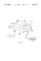
- FIG. 1 is a somewhat schematic perspective view illustrating a self-cleaning water filter constructed in accordance with the invention
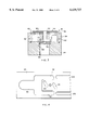
- FIG. 2 is an enlarged longitudinal vertical sectional view taken generally on the line 2--2 of FIG. 1;
- FIG. 3 is a transverse vertical sectional view taken generally on the line 3--3 of FIG. 2;
- FIG. 4 is a fragmented horizontal sectional view taken generally on the line 4--4 of FIG. 2;
- FIG. 5 is a fragmented horizontal sectional view taken generally on the line 5--5 of FIG. 2;
- FIG. 6 is a horizontal sectional view taken generally on the line 6--6 of FIG. 2;
- FIG. 7 is a fragmented horizontal sectional view taken generally on the line 7--7 of FIG. 2;
- FIG. 8 is a horizontal sectional view taken generally on the line 8--8 of FIG. 2;
- FIG. 9 is a fragmented elevation view depicting components of an index mechanism for rotation of a filter element
- FIG. 10 is a fragmented longitudinal vertical sectional view similar to a portion of FIG. 2, and showing a filter element in a clamped position;
- FIG. 11 is a horizontal sectional view similar to FIG. 8, but depicting an index mechanism in an advanced position.
- FIG. 1 illustrates the filter 10 utilized in an irrigation system wherein the filter is installed in-line along a water supply conduit 12 at a location downstream from a main system on-off control valve 14, to filter water supplied to a plurality of irrigation devices such as sprinkler heads or drip irrigation emitters referred to generally by reference numeral 16.
- the improved self-cleaning filter 10 includes a segmented filter element 18 (FIGS. 2 and 5) which is automatically backwashed or flushed clean in response to operation of the control valve 14 for cyclic on-off supply of water.
- the self-cleaning filter 10 of the present invention is designed to collect small particulate and fine debris present in the water supply, to prevent such particulate matter from flowing to the irrigation devices 16 and thereby avoid potential clogging and related undesired interference with the delivery of irrigation water to surrounding vegetation.
- the segmented filter element 18 is controllably positioned within the filter 10 by a pressure responsive index mechanism 20 to orient at least one filter segment for filtering incoming water, and at least one other filter segment for backwash flushing during an initial pressure rise transition period when the control valve 14 is turned on.
- filtered water is supplied to the irrigation devices 16 until the control valve 14 is turned off, at which time the index mechanism 20 responds to decreased pressure within the filter to index the filter element 18 so that the just-used filter segment is positioned for backwash flushing and a clean filter segment is positioned for filtering incoming water the next time the control valve 14 is turned on.
- This control valve 14 may, of course, be manually or automatically opened and closed to turn the water supply on and off.
- the self-cleaning filter 10 of the present invention is shown and described herein for use in an irrigation system, it will be recognized and understood that the filter may be employed in a wide variety of water and other fluid handling systems designed for cyclic on-off operation and wherein particulate filtering is desired.
- the illustrative filter 10 generally comprises a compact filter housing 22 formed by an assembled plurality of housing members which may be constructed from molded plastic and adapted for secure interconnection by appropriate fastener means (not shown) such as screws or the like. More particularly, in the preferred embodiment as shown, the housing 22 comprises an elongated base 24 defining a downwardly open inlet fitting 26 and a downwardly open outlet fitting 28 generally at opposite ends thereof for respective connection in-line with the water supply conduit 12 at a selected position downstream from the control valve 14. The inlet fitting 26 defines an open inflow port 30 for inflow of water to the filter 10 when the control valve 14 is turned on. As shown in FIGS.
- the inflow port 30 communicated with an inlet passage 32 extending through the base 24, and further through a portion of a central housing member 34 mounted thereon for water flow to the filter element 18, as will be described in more detail.
- a coarse mesh screen 36 is captured between the base 24 and the central housing member 34 to extend across this inlet passage 32 for collecting relatively large water-entrained debris that could otherwise potentially interfere with the desired index operation of the filter element 18. In a typical irrigation system installation, this coarse mesh screen 36 will require infrequent cleaning, and a drain port 38 is normally closed by a cap or plug 40 that can be manually removed to permit flush-cleaning of the upstream side of the screen 36 when required.
- the inlet passage 32 is shown to have a generally U-shaped configuration defining a split pair of downstream passage sections or branches extending through the central housing member 34 (FIG. 4) to the underside of a ported valve plate 42 sandwiched between an upper surface of the housing member 34 and an upper housing member 44 mounted thereon.
- the ported valve plate 42 defines a pair of inlet ports 46 (FIG. 6) disposed in open communication respectively with the split-apart downstream branches of the U-shaped inlet passage 32 for upward water flow into a filter chamber 48 (FIG. 2) formed within the upper housing member 44.
- the filter element 18 is supported and retained by the index mechanism 20 within the filter chamber 48 in sliding abutting contact with the upper surface of the valve plate 42, with a pair of filter segments 50 aligned with the inlet ports 46 (FIG. 3). Accordingly, water passing upwardly from the inlet passage 32 through the inlet ports 46 in the valve plate 42 is filtered by the filter segments 50 aligned with the inlet ports, whereby particulate entrained within the water flow is collected on the lower or upstream faces of the filter segments.
- the filter element 18 comprises a filter disk of generally circular shape. More particularly, as shown best in FIGS. 3 and 5 in accordance with one preferred construction, this filter disk includes a porous filter screen of selected fine mesh size supported by a frame of molded plastic or the like to include a central hub 52 joined by a plurality of outwardly radiating spokes 54 to an outer peripheral rim 56. Accordingly, the frame spokes 54 and rim 56 subdivide the filter screen into the plurality of filter segments 50 formed in a radially extending array. In the preferred form as depicted in the illustrative drawings, four spokes 54 are provided to subdivide the fine mesh filter screen into a plurality of four filter segments 50 each having an arcuate span of about 90°.
- a diametrically opposed pair of these filter segments 50 are aligned with the inlet ports 46 for filtering water flowing therethrough into the filter chamber 48.
- the remaining diametrically opposed pair of filter segments 50 are aligned respectively over a pair of flush ports 58 formed in the valve plate 42 (FIGS. 2 and 6) which communicate downwardly through a pair of split upstream sections of a flush passage 60 formed in the central housing member 34 and further to a flush outlet 62 in the base 24.
- a flush valve 61 (FIG. 2) is mounted at the flush outlet 62 and is retained in a normally open position by a spring 63 to permit water flow through the flush outlet 62 to a waste or drain site at the exterior of the filter housing 22.
- the filter element 18 is supported within the filter chamber 48 with the hub 52 rotatably carried on a support shaft 64.
- an upper end of the support shaft 64 is seated within a bearing bore 66 formed in the upper housing member 44, and a lower end of the support shaft extends through a resilient retention ring 68 which is captured between the base 24 and the central housing member 34.
- the lower end of the support shaft 64 is axially secured to the retention ring 68 as by capturing an inwardly directed flange of the ring 68 within a shallow groove defined between an axially presented shoulder and a radially enlarged washer 70 on the support shaft 64.
- the support shaft 64 is free to undergo a limited range of axial displacement according to the resilient characteristics of the retention ring 68, for releasibly clamping the filter element 18 against the valve plate 42 as will be described in more detail.
- the index mechanism 20 comprises a generally cup-shaped filter holder 72 which is also rotatably carried on the support shaft 64 in an inverted orientation, with a central mounting sleeve 74 retained axially between the hub 52 of the filter element 18 and a nut 76 threaded onto the support shaft.
- the filter holder 72 defines an outer or peripheral wall in the form of a plurality of downwardly extending drive fingers 78 sized and shaped for interlocking engagement with a plurality of outwardly radiating drive lugs 80 on the outer rim 56 of the filter element (FIG. 9). Accordingly, rotational movement of the filter holder 72 about the support shaft 64 results in a corresponding rotational movement of the filter element 18 relative to the underlying inlet ports 46 and the flush ports 58.
- the index mechanism 20 comprises a one-way clutch for unidirectional driving of the filter element 18. More particularly, a plurality of ramped ratchet teeth 82 (FIGS. 2 and 9) are formed on an upper surface of the filter holder 72 for rotary drive engagement with a matingly shaped plurality of clutch teeth 84 depending from a lower surface of a clutch plate 86.
- This clutch plate 86 is also rotatably carried on the support shaft 64. However, the clutch plate 86 also slides axially on the support shaft 64, and a biasing spring 88 reacts between an upper surface of the clutch plate 86 and an underside surface of a drive gear 90 to normally urge the clutch plate teeth 84 downwardly for engaging the ratchet teeth 82 on the filter holder 72.
- a plurality of drive pins 91 extend downwardly from the drive gear 90 for slide-fit reception through open ports in the clutch plate 86 (FIG. 2), whereby rotational motion of the drive gear 90 is transmitted to the clutch plate.
- the drive gear 90 is coupled in turn with a pressure responsive actuator 92 (FIG. 8) for unidirectionally rotating the clutch plate 86 in a manner to index the filter holder 72 and the filter element 18 carried thereby relative to the inlet and flush ports 46 and 58 formed in the valve plate 42.
- the pressure responsive actuator 92 (FIG. 8) comprises a drive rack pin 94 carried within the upper housing member 44 for axial sliding movement within an elongated bore 96.
- One side of this bore 96 is exposed to the filter chamber 48, to permit meshed coupling of the pin 94 with the drive gear 90 for rotating the drive gear back and forth in response to axial reciprocation of the pin 94 within the bore 96.
- one end of the pin 94 is secured to a piston head 98 which is coupled in turn to a resilient diaphragm 100 captured between an exterior surface of the upper housing member 44 and a cup-shaped cap 102 attached to the housing member 44.
- a biasing spring 106 reacts between the cap 102 and the piston head 98 to normally urge or advance the drive rack pin 94 axially inwardly toward the drive gear 90.
- the pressure within the filter chamber 48 will rise ultimately to a pressure level sufficient to retract the piston head 98 of the actuator 92 in an outboard direction relative to the drive gear 90.
- the drive rack pin 94 rotatably drives the gear 90 through an angular or arcuate increment of about 90°, until the piston head 98 bottoms against the actuator cap 102 as viewed in FIG. 8.
- the size and shape of the actuator cap 102 and the related piston head 98 are selected to achieve an arcuate rotation of the drive gear 90 of about 90°.
- the biasing spring 106 of the pressure responsive actuator 92 causes the drive rack pin 94 to translate in an opposite direction (FIG. 11), axially advancing into the bore 96 to drive the gear 90 through an equal rotational increment in an opposite rotational direction.
- the clutch plate 86 is also rotated through the same directional increment, but this time the clutch teeth 84 engage and drive the ratchet teeth 82 on the filter holder 72 to rotate the filter element 18 through a rotational increment of about 90°.
- Such rotation re-positions the filter segments 50 to reverse their alignment relative to the inlet ports 46 and the flush ports 58. In other words, the pair of filter segments previously aligned with the inlet ports 46 are rotated into alignment with the flush ports 58, and vice versa.
- the filter chamber 48 also communicates via an additional pair of outlet ports 108 (FIG. 6) formed in the valve plate 42 with an outlet passage 109 (FIG. 7) extending through the central housing member 34 toward the outlet fitting 28.
- An outlet valve 110 (FIG. 2) is mounted along this passage 109 and comprises a valve member 112 biased by a spring 114 to a normally closed position on a valve seat 116. As shown in FIG. 2, the valve member 112 is carried by a diaphragm 118, with the spring 114 reacting between one side of the valve member 112 and a vented support bracket 120 mounted on the upper housing member 44.
- the outlet valve 110 When water pressure within the filter chamber 48 rises to a sufficient pressure level, the outlet valve 110 is opened to permit flow of filtered water to and through the outlet fitting which defines an outflow port 122 in flow communication with the water supply conduit 12.
- the initial flow rate will be low but will increase as the filter segmented are cleaned.
- the pressure in the flush passage 60 is controlled in turn by the flow rate past the flush valve 61, wherein the flush valve 61 and the associated spring 63 are designed so that the pressure at the upstream side of the flush valve 61 will overcome the force applied by the spring 63 to close the flush valve against a seat 65 (FIG. 2) when the flow through the filter segments being backwashed is high enough to reflect an acceptable state of backwash cleaning.
- the water pressure within the filter chamber 48 rapidly increases to line pressure.
- the actuator 92 is pressure-operated for retraction of the drive rack pin 94 to back-rotate the clutch plate 86 through a 90° rotational increment without a corresponding rotation of the filter element 18.
- the water pressure increases to a higher second predetermined pressure level sufficient to open the outlet valve 110 for flow of filtered water to the irrigation devices 16.
- a bleed notch 124 (FIG. 2) may be provided in the outlet valve seat 116 to insure that the pressure within the filter chamber 48 will decrease substantially to atmospheric pressure when the control valve 14 is turned off.
- the outlet valve 110 closes followed by re-opening of the flush valve 61.
- the actuator 92 spring-advances the drive rack pin 94 to rotate the clutch plate 86 through a forward-drive increment of 90°, resulting in index rotation of the filter element 18 through a rotational step of 90°.
- this rotational indexing of the filter element 18 reverses the positions of the filter segments 50 relative to the inlet ports 46 and the flush ports 58. Specifically, the filter segments previously aligned with the inlet ports 46 for filtration are indexed into alignment with the flush ports 58 for backwashing when the control valve 14 is next turned on. Conversely, the filter segments previously aligned with the flush ports 58 for backwashing are aligned with the inlet ports 46 for filtration the next time the control valve 14 is turned on.
- the improved self-cleaning filter 10 of the present invention thus provides filtered water through the outlet fitting 28 to the irrigation devices 16 or other selected water usage site.
- the filter initially backwashes or flushes one or more previously used filter segments during an initial brief transition pressure rise period, for a time period sufficient to properly clean the filter segments, and thereafter supplies filtered water through the outlet fitting.
- the pressure responsive actuator 92 also responds to water pressure to reset the index mechanism 20 for index rotation of the filter element 18 when the control valve 14 is turned off. With this arrangement, clean filter segments are available for filtering incoming water, and previously used filter segments are backwashed, each time the control valve is turned on.
- filter element 18 has been shown and described in the form of a single filter disk subdivided by the spoked frame into multiple filter segments, it will be recognized and understood that these filter segments may comprise a plurality of individual filter members carried by a common frame for movement along a selected index path of nonlinear or linear shape into appropriate alignment with an inlet port 46 and a flush port 58.
- filter element configuration as shown, it will be further recognized and understood that any selected number of multiple filter segments may be used, with appropriate incremental rotation.
- a single flush port 58 may be provided for alignment with a single filter segment, with the remaining filter segments aligned with associated inlet ports 46, whereby each filter segment may be used for two or more filter cycles in succession prior to displacement into alignment with the flush port 58 for a flush cycle.
Landscapes
- Chemical & Material Sciences (AREA)
- Chemical Kinetics & Catalysis (AREA)
- Filtration Of Liquid (AREA)
Abstract
Description
Claims (26)
Priority Applications (1)
| Application Number | Priority Date | Filing Date | Title |
|---|---|---|---|
| US09/260,690 US6139727A (en) | 1999-03-02 | 1999-03-02 | Self-cleaning water filter |
Applications Claiming Priority (1)
| Application Number | Priority Date | Filing Date | Title |
|---|---|---|---|
| US09/260,690 US6139727A (en) | 1999-03-02 | 1999-03-02 | Self-cleaning water filter |
Publications (1)
| Publication Number | Publication Date |
|---|---|
| US6139727A true US6139727A (en) | 2000-10-31 |
Family
ID=22990201
Family Applications (1)
| Application Number | Title | Priority Date | Filing Date |
|---|---|---|---|
| US09/260,690 Expired - Lifetime US6139727A (en) | 1999-03-02 | 1999-03-02 | Self-cleaning water filter |
Country Status (1)
| Country | Link |
|---|---|
| US (1) | US6139727A (en) |
Cited By (27)
| Publication number | Priority date | Publication date | Assignee | Title |
|---|---|---|---|---|
| US20040069703A1 (en) * | 2002-09-18 | 2004-04-15 | Wanni Amar S. | Fouling mitigation device with movable screen |
| US6758344B2 (en) | 2002-02-21 | 2004-07-06 | Gordon Construction, Inc. | Self-cleaning fluid filter system |
| US20050115886A1 (en) * | 2003-12-01 | 2005-06-02 | Choo Kim P. | Backflushing filter |
| US20050139531A1 (en) * | 2002-02-21 | 2005-06-30 | Gordon Robert R. | Method and system for filtering sediment-bearing fluids |
| US20050199551A1 (en) * | 2004-03-10 | 2005-09-15 | Gordon Robert R. | Method and system for filtering sediment-bearing fluids |
| US20050241282A1 (en) * | 2004-04-28 | 2005-11-03 | Gordon Robert R | Self cleaning gas filtering system and method |
| US20060117774A1 (en) * | 2004-12-01 | 2006-06-08 | Fujikoki Corporation | Pressure control valve |
| US20060131220A1 (en) * | 2004-03-29 | 2006-06-22 | Rain Bird Corporation | Pressure regulator and filter for irrigation systems |
| US20070187328A1 (en) * | 2004-03-10 | 2007-08-16 | Gordon Robert R | Method and system for filtering sediment-bearing fluids |
| US20080251742A1 (en) * | 2005-02-24 | 2008-10-16 | Sadatake Ise | Pressure Control Valve |
| US20090217777A1 (en) * | 2008-03-03 | 2009-09-03 | Hanson William P | Analyte screening and detection systems and methods |
| US20100078395A1 (en) * | 2008-09-24 | 2010-04-01 | Jerry Shevitz | Screen Filter Module for Alternating Flow Filtration |
| US7691602B1 (en) | 2007-03-02 | 2010-04-06 | Hanson Technologies, Inc. | Agricultural screening system and method for detection of infectious microorganisms |
| CN102343175A (en) * | 2011-10-10 | 2012-02-08 | 上海众一石化工程有限公司 | Self-cleaning filter |
| CN102380251A (en) * | 2011-09-19 | 2012-03-21 | 北京矿大节能科技有限公司 | Full-automatic mining wastewater filter and operation method thereof |
| CN104722128A (en) * | 2015-03-05 | 2015-06-24 | 厦门建霖工业有限公司 | Easy-to-exchange multi-interlayer filter element |
| US9446354B2 (en) | 2010-08-25 | 2016-09-20 | Repligen Corporation | Device, system and process for modification or concentration of cell-depleted fluid |
| CN106400872A (en) * | 2016-11-07 | 2017-02-15 | 青岛智享专利技术开发有限公司 | A rotating self-cleaning device for the ground of a landscape pool |
| CN108799562A (en) * | 2018-07-17 | 2018-11-13 | 北京华金浩环保供水设备有限公司 | The dual backwashed trap valve of one kind and filter method |
| US10549222B2 (en) | 2013-08-04 | 2020-02-04 | Tavlit Plastic Ltd. | Self cleaning disc filter apparatus |
| US11156219B2 (en) | 2015-11-10 | 2021-10-26 | Repligen Corporation | Disposable alternating tangential flow filtration units |
| US11284572B2 (en) | 2014-12-05 | 2022-03-29 | Pivot Pup Irrigation, LLC | Irrigating soils and crops |
| CN114304672A (en) * | 2021-12-21 | 2022-04-12 | 贵州辣得笑食品有限公司 | Food raw material cleaning system |
| CN117547773A (en) * | 2023-11-20 | 2024-02-13 | 江苏铭星供水设备有限公司 | A smart assembled fire box pump |
| US12443208B2 (en) | 2023-02-08 | 2025-10-14 | Rain Bird Corporation | Control zone devices, systems and methods |
| US12498049B2 (en) | 2024-03-29 | 2025-12-16 | Rain Bird Corporation | Zone control devices, systems and methods |
| US12612587B2 (en) | 2017-05-12 | 2026-04-28 | Jerry Shevitz | Bioreactors |
Citations (1)
| Publication number | Priority date | Publication date | Assignee | Title |
|---|---|---|---|---|
| US2237964A (en) * | 1938-11-01 | 1941-04-08 | Thomas E Haught | Screen cleaning means |
-
1999
- 1999-03-02 US US09/260,690 patent/US6139727A/en not_active Expired - Lifetime
Patent Citations (1)
| Publication number | Priority date | Publication date | Assignee | Title |
|---|---|---|---|---|
| US2237964A (en) * | 1938-11-01 | 1941-04-08 | Thomas E Haught | Screen cleaning means |
Cited By (44)
| Publication number | Priority date | Publication date | Assignee | Title |
|---|---|---|---|---|
| US7241382B2 (en) | 2002-02-21 | 2007-07-10 | Gordon Construction Inc. | Method and system for filtering sediment-bearing fluids |
| US6758344B2 (en) | 2002-02-21 | 2004-07-06 | Gordon Construction, Inc. | Self-cleaning fluid filter system |
| US6875364B2 (en) | 2002-02-21 | 2005-04-05 | Gordon Construction, Inc. | Self-cleaning fluid filter system |
| US20050139531A1 (en) * | 2002-02-21 | 2005-06-30 | Gordon Robert R. | Method and system for filtering sediment-bearing fluids |
| US6811685B2 (en) | 2002-09-18 | 2004-11-02 | Exxonmobil Research And Engineering Company | Fouling mitigation device with movable screen |
| US20040069703A1 (en) * | 2002-09-18 | 2004-04-15 | Wanni Amar S. | Fouling mitigation device with movable screen |
| US20050115886A1 (en) * | 2003-12-01 | 2005-06-02 | Choo Kim P. | Backflushing filter |
| US7105090B2 (en) * | 2003-12-01 | 2006-09-12 | Kim Poh Choo | Backflushing filter |
| US20070144969A1 (en) * | 2004-03-10 | 2007-06-28 | Gordon Construction, Inc. | Method and system for filtering sediment-bearing fluids |
| US20050199551A1 (en) * | 2004-03-10 | 2005-09-15 | Gordon Robert R. | Method and system for filtering sediment-bearing fluids |
| US20070187328A1 (en) * | 2004-03-10 | 2007-08-16 | Gordon Robert R | Method and system for filtering sediment-bearing fluids |
| US20060131220A1 (en) * | 2004-03-29 | 2006-06-22 | Rain Bird Corporation | Pressure regulator and filter for irrigation systems |
| US8187471B2 (en) | 2004-03-29 | 2012-05-29 | Rain Bird Corporation | Pressure regulator and filter for irrigation systems |
| US20100116754A1 (en) * | 2004-03-29 | 2010-05-13 | Rain Bird Corporation | Pressure Regulator and Filter for Irrigation Systems |
| US7628910B2 (en) | 2004-03-29 | 2009-12-08 | Rain Bird Corporation | Pressure regulator and filter for irrigation systems |
| US20050241282A1 (en) * | 2004-04-28 | 2005-11-03 | Gordon Robert R | Self cleaning gas filtering system and method |
| US7468082B2 (en) | 2004-04-28 | 2008-12-23 | Gordon Robert R | Self cleaning gas filtering system and method |
| US20060117774A1 (en) * | 2004-12-01 | 2006-06-08 | Fujikoki Corporation | Pressure control valve |
| US20080251742A1 (en) * | 2005-02-24 | 2008-10-16 | Sadatake Ise | Pressure Control Valve |
| US7691602B1 (en) | 2007-03-02 | 2010-04-06 | Hanson Technologies, Inc. | Agricultural screening system and method for detection of infectious microorganisms |
| US20090217777A1 (en) * | 2008-03-03 | 2009-09-03 | Hanson William P | Analyte screening and detection systems and methods |
| US8857279B2 (en) | 2008-03-03 | 2014-10-14 | William P. Hanson | Analyte screening and detection systems and methods |
| US20100078395A1 (en) * | 2008-09-24 | 2010-04-01 | Jerry Shevitz | Screen Filter Module for Alternating Flow Filtration |
| US9050547B2 (en) | 2008-09-24 | 2015-06-09 | Repligen Corporation | Screen filter module for alternating flow filtration |
| US9993751B2 (en) | 2008-09-24 | 2018-06-12 | Repligen Corporation | Screen filter module for alternating flow filtration |
| US11225637B2 (en) | 2010-08-25 | 2022-01-18 | Repligen Corporation | Enclosed filtration system processes |
| US9446354B2 (en) | 2010-08-25 | 2016-09-20 | Repligen Corporation | Device, system and process for modification or concentration of cell-depleted fluid |
| US10081788B2 (en) | 2010-08-25 | 2018-09-25 | Repligen Corporation | Device, system and process for modification or concentration of cell-depleted fluid |
| CN102380251A (en) * | 2011-09-19 | 2012-03-21 | 北京矿大节能科技有限公司 | Full-automatic mining wastewater filter and operation method thereof |
| CN102343175A (en) * | 2011-10-10 | 2012-02-08 | 上海众一石化工程有限公司 | Self-cleaning filter |
| US10549222B2 (en) | 2013-08-04 | 2020-02-04 | Tavlit Plastic Ltd. | Self cleaning disc filter apparatus |
| US11284572B2 (en) | 2014-12-05 | 2022-03-29 | Pivot Pup Irrigation, LLC | Irrigating soils and crops |
| CN104722128B (en) * | 2015-03-05 | 2016-08-24 | 厦门建霖工业有限公司 | A kind of easily replacing many interlayers filter element |
| CN104722128A (en) * | 2015-03-05 | 2015-06-24 | 厦门建霖工业有限公司 | Easy-to-exchange multi-interlayer filter element |
| US11156219B2 (en) | 2015-11-10 | 2021-10-26 | Repligen Corporation | Disposable alternating tangential flow filtration units |
| CN106400872B (en) * | 2016-11-07 | 2018-10-16 | 钱佳敏 | A rotating self-cleaning device for the ground of a landscape pool |
| CN106400872A (en) * | 2016-11-07 | 2017-02-15 | 青岛智享专利技术开发有限公司 | A rotating self-cleaning device for the ground of a landscape pool |
| US12612587B2 (en) | 2017-05-12 | 2026-04-28 | Jerry Shevitz | Bioreactors |
| CN108799562A (en) * | 2018-07-17 | 2018-11-13 | 北京华金浩环保供水设备有限公司 | The dual backwashed trap valve of one kind and filter method |
| CN114304672A (en) * | 2021-12-21 | 2022-04-12 | 贵州辣得笑食品有限公司 | Food raw material cleaning system |
| US12443208B2 (en) | 2023-02-08 | 2025-10-14 | Rain Bird Corporation | Control zone devices, systems and methods |
| CN117547773A (en) * | 2023-11-20 | 2024-02-13 | 江苏铭星供水设备有限公司 | A smart assembled fire box pump |
| CN117547773B (en) * | 2023-11-20 | 2024-05-14 | 江苏铭星供水设备有限公司 | A smart assembled fire box pump |
| US12498049B2 (en) | 2024-03-29 | 2025-12-16 | Rain Bird Corporation | Zone control devices, systems and methods |
Similar Documents
| Publication | Publication Date | Title |
|---|---|---|
| US6139727A (en) | Self-cleaning water filter | |
| US6575307B2 (en) | Self-cleaning water filter | |
| US4781825A (en) | Filter with self-actuating rotating backwash selector | |
| US4081171A (en) | Self-cleaning filter assembly for solenoid-actuated valves | |
| US9211489B2 (en) | Self-cleaning filter module | |
| CA1274745A (en) | Automatic valve for use with pool cleaning device | |
| GB2034592A (en) | Backwashable filtering device | |
| US10245531B2 (en) | High-efficiency automatic self-cleaning strainer | |
| JPH026565B2 (en) | ||
| US20080047885A1 (en) | Filter Cleaning Head | |
| US4614581A (en) | Backwashable filter | |
| KR101985583B1 (en) | Filter Employing Stack of Filter Disks | |
| CN1068237C (en) | Liquid Filtration Equipment | |
| US4722794A (en) | Straining and stop valve | |
| CN101730570A (en) | Drain valve and method for filter maintenance | |
| US20080047890A1 (en) | Filter device and parts thereof and a method for operation of the filter device | |
| KR102608983B1 (en) | Rotary filter filtration system with backwash function | |
| US4944887A (en) | Regenerative diatomaceous earth filter | |
| US4422938A (en) | Backwashing-type filtering apparatus | |
| US5032268A (en) | Self-contained canister unit for filtering tap water | |
| EP0993853A2 (en) | A device for filtering liquid substances | |
| CN111686494A (en) | Filter assembly | |
| US6196395B1 (en) | Filter device and method of operating same | |
| WO2000072939A1 (en) | Filter for fluids | |
| CN111520508B (en) | Multifunctional fluid valve |
Legal Events
| Date | Code | Title | Description |
|---|---|---|---|
| AS | Assignment |
Owner name: ANTHONY MANUFACTURING CORPORATION, CALIFORNIA Free format text: ASSIGNMENT OF ASSIGNORS INTEREST;ASSIGNOR:LOCKWOOD, GEORGE H.;REEL/FRAME:010433/0346 Effective date: 19991124 |
|
| STCF | Information on status: patent grant |
Free format text: PATENTED CASE |
|
| AS | Assignment |
Owner name: RAIN BIRD CORPORATION, CALIFORNIA Free format text: ASSIGNMENT OF ASSIGNORS INTEREST;ASSIGNOR:ANTHONY MANUFACTURING CORP.;REEL/FRAME:012407/0584 Effective date: 20011127 |
|
| FPAY | Fee payment |
Year of fee payment: 4 |
|
| FEPP | Fee payment procedure |
Free format text: PAYOR NUMBER ASSIGNED (ORIGINAL EVENT CODE: ASPN); ENTITY STATUS OF PATENT OWNER: LARGE ENTITY |
|
| FPAY | Fee payment |
Year of fee payment: 8 |
|
| REMI | Maintenance fee reminder mailed | ||
| FPAY | Fee payment |
Year of fee payment: 12 |