EP3370042A1 - Mehrspurwaage - Google Patents
Mehrspurwaage Download PDFInfo
- Publication number
- EP3370042A1 EP3370042A1 EP18167484.7A EP18167484A EP3370042A1 EP 3370042 A1 EP3370042 A1 EP 3370042A1 EP 18167484 A EP18167484 A EP 18167484A EP 3370042 A1 EP3370042 A1 EP 3370042A1
- Authority
- EP
- European Patent Office
- Prior art keywords
- track
- weighing devices
- track scale
- weighing
- belt
- Prior art date
- Legal status (The legal status is an assumption and is not a legal conclusion. Google has not performed a legal analysis and makes no representation as to the accuracy of the status listed.)
- Granted
Links
Images


Classifications
-
- G—PHYSICS
- G01—MEASURING; TESTING
- G01G—WEIGHING
- G01G11/00—Apparatus for weighing a continuous stream of material during flow; Conveyor belt weighers
- G01G11/04—Apparatus for weighing a continuous stream of material during flow; Conveyor belt weighers having electrical weight-sensitive devices
- G01G11/043—Apparatus for weighing a continuous stream of material during flow; Conveyor belt weighers having electrical weight-sensitive devices combined with totalising or integrating devices
-
- G—PHYSICS
- G01—MEASURING; TESTING
- G01G—WEIGHING
- G01G11/00—Apparatus for weighing a continuous stream of material during flow; Conveyor belt weighers
Definitions
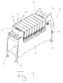
- the present invention relates to a multi-track weigher, in particular a multi-track weigher, with a plurality of juxtaposed, each forming a track of the multi-track weigher belt weighing.
- Such multi-track scales are designed to weigh in a production line multi-track incoming cargo such as packages, bottles or food portions in parallel, so that compared to a single-track scale, a higher throughput can be achieved.
- one of the belt weighing devices fails or if there are other problems with the belt weighing device, it must be replaced by another belt weighing device.
- the replacement of the defective belt weighing device costs time during which the multi-track scale is stationary.
- the invention has for its object to provide a multi-track scale of the type mentioned, which makes it possible to minimize downtime.
- a modular multitrack scale makes it easy and quick to change the respective belt weighing device in case of failure or other problems with a single track. Due to the quick replaceability Downtimes can be minimized for the individual belt weighing equipment.
- the multi-track scale which is equipped with belt weighing a certain track width, can be easily and quickly converted to belt weighing with a different track width. This also minimizes downtime.
- the band weighing devices are designed as modules or modules, i. as separately manageable, interchangeable, complex parts of the multi-track scale, each forming a closed functional unit.
- the belt weighing devices are arranged side by side with respect to the transport direction of the multi-track scale, which transport direction is preferably the same for all tracks.
- the multi-track weigher on a particular fixed frame or base frame on which the band weighing devices are supported.
- the band weighing devices are each movable transversely, in particular perpendicular to the transport direction, in particular slidably mounted.
- the mobility is infinitely formed, so that the band weighing devices can be placed within predetermined limits ultimately at any point transverse to the transport direction.
- this does not exclude that the respective band weighing device can be fixed immovably by an operable clamping device explained in more detail below.
- the belt weighing devices are each mounted on a carrier device with at least one cross member, in particular slide-mounted.
- the carrier device is preferably a carrier device which is suitable for all belt weighing devices is common.
- the respective cross member may be formed, for example, as a round rod, T-beam or square bar.
- the band weighing devices in the radial direction of the at least one cross member are removable, in particular upwards.
- the radial direction refers to the longitudinal direction or longitudinal extent of the cross member or beams.
- a belt weighing device located between other belt weighing devices can hereby be removed from the multi-track scale without the need to disassemble other belt weighing devices.
- the belt weighing devices may each comprise at least one in particular manually operable clamping device in order to fix the respective belt weighing device to the carrier device.
- the respective clamping device is adjustable between a clamping position and a release position. The respective belt weighing device can thereby be held securely on the carrier device.
- With two or more cross members a corresponding number of clamping devices is provided.
- the carrier device is pivotable between an operating position and a service position.
- the multi-track weigher In the operating position of the carrier device, the multi-track weigher can be operated as intended.
- In the service position access to the belt weighing devices is facilitated so that, for example, cleaning, replacement of a transport belt, a module change or, in particular, other service can be carried out more easily.
- This increases the service-friendliness of the multi-track scale.
- the pivot axis is oriented parallel to the transport direction of the multi-track scale.
- the aforementioned at least one cross member in the Operating position arranged at least substantially horizontally, and tilted in the service position against the horizontal.
- a common motor for driving the bands of the band weighing devices is provided for the band weighing devices.
- the motor which may be, for example, a drum motor, is preferably attached to the aforementioned frame.
- the band of the respective belt weighing devices is driven by a drive shaft, which is arranged below the outlet-side end of the weighing support of the respective belt weighing device, which construction is also referred to as Rüberziehtex.
- the belt weighing devices can be used, for example, via couplings, drive shafts or other elements, e.g. Springs, or wave geometries, e.g. Tongue and groove, to be connected to the engine.
- drive shafts or other elements e.g. Springs
- wave geometries e.g. Tongue and groove
- the conveying speed for all belt weighing devices can be designed to be the same size and synchronous.
- the belt weighing devices each comprise a weighing platform and a further platform adjoining the weighing platform, the platforms each having a length extending in the transport direction, and wherein at least the weighing platform is adjustable in length, namely expandable and collapsible.
- Fig. 1 and 2 illustrated multi-track weigher comprises a base frame 11 which is supported on the floor via four feet 13.
- a support means 15 between the in Fig. 1 shown operating position and the in Fig. 2 shown service position mounted pivotally.
- the belt weighing devices 19 each form a track of the multi-track scale and are each designed as a dynamic checkweigher, so that the multi-track scale represents a checkweigher.
- the goods to be weighed are weighed in the pass, that is, the measurements are made while the particular equilibrium goods move over the weighing platform without stopping due to a continuous movement of a respective transport belt 21.
- the belt weighing devices 19 and the multi-track scales can also be designed as a pricing device, in particular for dynamically weighing non-equilibrium goods.
- the transport direction 23 of the belt weighing devices 19 is indicated by an arrow.
- the support means 15 comprises two cross members 25, each extending perpendicular to the transport direction 23 and each having a first end 27 and a second end 29.
- the first ends 27 of the cross member 25 are fixedly connected to a first end plate 31 of the support means 15 ( Fig. 1 . 2 ) which is rotatably supported about the pivot axis 17.
- the second ends 29 are fixedly connected to a second end plate 33.
- the belt weighing devices 19 are slidably mounted on the two cross beams 25, i. the belt weighing devices 19 can each individually - unless they are clamped, as will be explained in more detail below - are moved continuously along the cross member 25. In the assembled state of the multi-track weigher all band weighing devices 19 between the end plates 31, 33 are arranged.
- the band weighing devices 19 are each designed as a module, which can be removed as a whole from the carrier device 15 and exchanged or placed on the carrier device 15.
- the band weighing devices 19 each form self-supporting, composed of individual parts Units.
- the multi-track scale thus has a modular design. In the event of failure of a belt weighing device 19, the respective belt weighing device can therefore be replaced easily and quickly, whereby downtime, in which the multi-track scale is not operated, can be minimized.
- the belt weighing devices 19 can be removed upwards or radially away from the two transverse beams 25 away from the multi-track scale or the belt weighing devices 19 can be used from radially with respect to the cross beams 25 in the multi-track scale.
- a frame 35 of the respective band weighing device 19 is provided with two transverse, downwardly open recesses 37, via which the respective band weighing device 19 can be placed on the cross member 25.
- the respective band weighing device 19 comprises two operable clamping devices 39, which are each formed as a clamp or annular clamp to clamp the two cross members 25 in the recesses 37 and thus to fix the respective band weighing device 19 immovably to the cross members 25.
- the conveyor belts 21 of the belt weighing devices 19 are driven by a common drive shaft 41 ( Fig. 3 . 4 ), which in turn is driven by a single motor 49 ( Fig. 1 . 2 ).
- the drive shaft 41 is arranged below the outlet-side end of the weighing support 51 of the respective belt weighing device 19. Furthermore, it is off Fig. 4 It can be seen that the respective belt weighing device 19 has a weighing platform 43, which acts on a weighing cell 47, and a discharge platform 45, each of which is adjustable in length, the overall length of the two platforms 43, 45 always remaining the same.
- the belt weighing device 19 is described in more detail in an application filed by the applicant with the German Patent and Trademark Office entitled “Weighing device” and the official file reference 10 2009 060 291.7. This application is incorporated by reference into the disclosure of the present application with respect to the design of the belt weighing device.
- the multi-track weigher can be operated as intended.
- the in Fig. 2 shown service position in which the support means is folded up with the band weighing devices 19, the access to the belt weighing 19 is facilitated, so that a cleaning, a change of a band weighing device or a service is largely barrier-free possible.
- the conveyor belts 21 can be dismantled or removed easily and quickly, in particular without tools, for cleaning purposes. This is made possible, in particular, by the fact that a common transport belt 21 is provided for the weighing platform 43 and the discharge platform 45, and not two separate transport belts.
Landscapes
- Physics & Mathematics (AREA)
- General Physics & Mathematics (AREA)
- Structure Of Belt Conveyors (AREA)
Abstract
Description
- Die vorliegende Erfindung betrifft eine Mehrspurwaage, insbesondere eine Mehrspurkontrollwaage, mit mehreren nebeneinander angeordneten, jeweils eine Spur der Mehrspurwaage bildenden Bandwägeeinrichtungen.
- Derartige Mehrspurwaagen sind dazu ausgelegt, in einer Produktionslinie mehrspurig ankommende Stückgüter wie Pakete, Flaschen oder Lebensmittelportionen parallel zu wiegen, so dass gegenüber einer einspurigen Waage ein höherer Durchsatz erzielbar ist.
- Fällt eine der Bandwägeeinrichtungen aus oder gibt es sonstige Probleme mit der Bandwägeeinrichtung, muss diese durch eine andere Bandwägeeinrichtung ersetzt werden. Der Austausch der defekten Bandwägeeinrichtung kostet jedoch Zeit, während der die Mehrspurwaage stillsteht.
- Der Erfindung liegt die Aufgabe zugrunde, eine Mehrspurwaage der eingangs genannten Art anzugeben, die es ermöglicht, Stillstandzeiten zu minimieren.
- Diese Aufgabe wird durch die Merkmale des Anspruchs 1 gelöst, und insbesondere dadurch, dass die Bandwägeeinrichtungen jeweils als ein austauschbares Modul ausgebildet sind.
- Eine modular aufgebaute Mehrspurwaage ermöglicht, bei Ausfall oder sonstigen Problemen mit einer Spur die jeweilige Bandwägeeinrichtung einfach und schnell zu wechseln. Durch die schnelle Auswechselbarkeit der einzelnen Bandwägeeinrichtungen können Stillstandzeiten minimiert werden. Darüber hinaus kann die Mehrspurwaage, die mit Bandwägeeinrichtungen einer bestimmten Spurbreite bestückt ist, einfach und schnell auf Bandwägeeinrichtungen mit einer anderen Spurbreite umgerüstet werden. Auch hierdurch können Stillstandzeiten minimiert werden.
- Insbesondere sind die Bandwägeeinrichtungen als Baueinheiten bzw. als Module ausgebildet, d.h. als separat handhabbare, austauschbare, komplexe Teile der Mehrspurwaage, die jeweils eine geschlossene Funktionseinheit bilden. Die Bandwägeeinrichtungen sind bezüglich der Transportrichtung der Mehrspurwaage nebeneinander angeordnet, welche Transportrichtung bevorzugt für alle Spuren dieselbe ist. Vorzugsweise weist die Mehrspurwaage ein insbesondere feststehendes Gestell oder Grundgestell auf, an dem die Bandwägeeinrichtungen gehaltert sind.
- Bevorzugt sind die Bandwägeeinrichtungen jeweils quer, insbesondere senkrecht zur Transportrichtung bewegbar, insbesondere verschiebbar gelagert. Bevorzugt ist die Bewegbarkeit stufenlos ausgebildet, so dass die Bandwägeeinrichtungen innerhalb vorgegebener Grenzen letztlich an beliebiger Stelle quer zur Transportrichtung platzierbar sind. Dies schließt jedoch nicht aus, dass die jeweilige Bandwägeeinrichtung durch eine nachstehend noch näher erläuterte betätigbare Klemmeinrichtung unverschiebbar fixiert werden kann.
- Beispielsweise sind die Bandwägeeinrichtungen jeweils auf einer Trägereinrichtung mit wenigstens einem Querträger gelagert, insbesondere gleitgelagert. Insbesondere sind zwei oder mehr parallel zueinander verlaufende Querträger vorgesehen. Bevorzugt handelt es sich bei der Trägereinrichtung um eine Trägereinrichtung, die für sämtliche Bandwägeeinrichtungen gemeinsam ist. Der jeweilige Querträger kann beispielsweise als Rundstab, T-Träger oder Vierkantstab ausgebildet sein.
- Nach einer Ausbildung der Erfindung sind die Bandwägeeinrichtungen in radialer Richtung von dem wenigstens einen Querträger abnehmbar, insbesondere nach oben hin. Die radiale Richtung bezieht sich auf die Längsrichtung bzw. Längserstreckung des oder der Querträger. Eine Bandwägeeinrichtung, die sich zwischen anderen Bandwägeeinrichtungen befindet, kann hierdurch von der Mehrspurwaage abgenommen werden, ohne dass hierfür andere Bandwägeeinrichtungen demontiert werden müssen.
- Die Bandwägeeinrichtungen können jeweils wenigstens eine insbesondere manuell betätigbare Klemmeinrichtung umfassen, um die jeweilige Bandwägeeinrichtung an der Trägereinrichtung zu fixieren. Insbesondere ist die jeweilige Klemmeinrichtung zwischen einer Klemmstellung und einer Freigabestellung verstellbar. Die jeweilige Bandwägeeinrichtung kann dadurch sicher an der Trägereinrichtung gehaltert werden. Bei zwei oder mehr Querträgern ist eine entsprechende Anzahl an Klemmeinrichtungen vorgesehen.
- Vorzugsweise ist die Trägereinrichtung zwischen einer Betriebsstellung und einer Servicestellung verschwenkbar. In der Betriebsstellung der Trägereinrichtung kann die Mehrspurwaage bestimmungsgemäß betrieben werden. In der Servicestellung ist der Zugang zu den Bandwägeeinrichtungen erleichtert, so dass beispielsweise eine Reinigung, ein Tausch eines Transportgurts, ein Modulwechsel oder ein insbesondere sonstiger Service einfacher ausgeführt werden kann. Hierdurch wird die Servicefreundlichkeit der Mehrspurwaage erhöht. Insbesondere ist die Schwenkachse parallel zu der Transportrichtung der Mehrspurwaage orientiert. Bevorzugt ist der vorgenannte wenigstens eine Querträger in der Betriebsstellung zumindest im Wesentlichen waagrecht angeordnet, und in der Servicestellung gegen die Waagrechte geneigt.
- Nach einer Ausführungsform der Erfindung ist für die Bandwägeeinrichtungen ein gemeinsamer Motor zum Antrieb der Bänder der Bandwägeeinrichtungen vorgesehen. Der Motor, bei dem es sich beispielsweise um einen Trommelmotor handeln kann, ist bevorzugt an dem vorgenannten Gestell befestigt.
- Bevorzugt wird das Band der jeweiligen Bandwägeeinrichtungen von einer Antriebswelle angetrieben, die unterhalb des auslaufseitigen Endes der Wägeauflage der jeweiligen Bandwägeeinrichtung angeordnet ist, welche Konstruktion auch als Rüberziehprinzip bezeichnet wird.
- Die Bandwägeeinrichtungen können beispielsweise über Kupplungen, Gelenkwellen oder sonstige Elemente, z.B. Federn, oder Wellengeometrien, z.B. Nut und Feder, mit dem Motor verbunden sein. Bevorzugt ist es jedoch, wenn für die Bandwägeeinrichtungen eine gemeinsame Antriebswelle vorgesehen ist. Dadurch kann die Fördergeschwindigkeit für sämtliche Bandwägeeinrichtungen gleich groß und synchron gestaltet werden.
- Vorzugsweise umfassen die Bandwägeeinrichtungen jeweils eine Wägeplattform und eine an die Wägeplattform anschließende weitere Plattform, wobei die Plattformen jeweils eine sich in Transportrichtung erstreckende Länge aufweisen, und wobei zumindest die Wägeplattform längenverstellbar, nämlich auseinanderziehbar und zusammenschiebbar, ausgebildet ist.
- Weitere vorteilhafte Ausgestaltungen der Erfindung sind in den Unteransprüchen, der Figurenbeschreibung und der Zeichnung beschrieben.
- Die Erfindung wird im Folgenden beispielhaft unter Bezugnahme auf die Zeichnung beschrieben. Es zeigen,
- Fig. 1
- eine perspektivische Ansicht einer erfindungsgemäßen Mehrspurwaage mit mehreren nebeneinander angeordneten Bandwägeeinrichtungen, die auf einer Trägereinrichtung vorgesehen sind, welche sich in einer Betriebsstellung befindet,
- Fig. 2
- die Mehrspurwaage aus
Fig. 1 , wobei sich die Trägereinrichtung in einer Servicestellung befindet, - Fig. 3
- die Trägervorrichtung aus den
Fig. 1 und2 mit Querträgern und eine einzelne Bandwägeeinrichtung, und - Fig. 4
- eine Seitenansicht einer einzelnen Bandwägeeinrichtung.
- Die in
Fig. 1 und2 dargestellte Mehrspurwaage umfasst ein Grundgestell 11, das über vier Standfüße 13 auf dem Boden abgestützt ist. An dem Grundgestell 11 ist eine Trägereinrichtung 15 zwischen der inFig. 1 gezeigten Betriebsstellung und der inFig. 2 gezeigten Servicestellung verschwenkbar angebracht. Die schwenkbare Lagerung der Trägereinrichtung 15 an dem Grundgestell 11 erfolgt über eine Schwenkachse 17. - Darüber hinaus sind in den
Fig. 1 und2 insgesamt acht, auf der Trägereinrichtung 15 angeordnete Bandwägeeinrichtungen 19 erkennbar, um mehrspurig an der Mehrspurwaage ankommende Stückgüter wie Pakete, Flaschen oder Lebensmittelportionen parallel zu wiegen. Die Bandwägeeinrichtungen 19 bilden jeweils eine Spur der Mehrspurwaage und sind jeweils als dynamische Kontrollwaage ausgebildet, so dass auch die Mehrspurwaage eine Kontrollwaage darstellt. Bei einer dynamischen Kontrollwaage werden die zu wiegenden Waren im Durchlauf gewogen, d.h. die Messungen werden vorgenommen, während sich die insbesondere gleichgewichtigen Waren aufgrund einer kontinuierlichen Bewegung eines jeweiligen Transportgurts 21 ohne Stopp über die Wägeplattform hinwegbewegen. Grundsätzlich können die Bandwägeeinrichtungen 19 jeweils und die Mehrspurwaage auch als Preisauszeichner ausgebildet sein, insbesondere zum dynamischen Wiegen ungleichgewichtiger Waren. Die Transportrichtung 23 der Bandwägeeinrichtungen 19 ist durch einen Pfeil gekennzeichnet. - Wie insbesondere aus
Fig. 3 ersichtlich ist, umfasst die Trägereinrichtung 15 zwei Querträger 25, die sich jeweils senkrecht zur Transportrichtung 23 erstrecken und jeweils ein erstes Ende 27 und eine zweites Ende 29 aufweisen. Die ersten Enden 27 der Querträger 25 sind fest mit einem ersten Abschlussblech 31 der Trägereinrichtung 15 verbunden (Fig. 1 ,2 ), das um die Schwenkachse 17 drehbar gelagert ist. Die zweiten Enden 29 sind fest mit einem zweiten Abschlussblech 33 verbunden. - Die Bandwägeeinrichtungen 19 sind auf den zwei Querträgern 25 gleitgelagert, d.h. die Bandwägeeinrichtungen 19 können jeweils einzeln - sofern sie nicht festgeklemmt sind, wie nachstehend nach näher erläutert wird - entlang der Querträger 25 stufenlos verschoben werden. Im zusammengesetzten Zustand der Mehrspurwaage sind sämtliche Bandwägeeinrichtungen 19 zwischen den Abschlussblechen 31, 33 angeordnet.
- Die Bandwägeeinrichtungen 19 sind jeweils als ein Modul ausgebildet, das als Ganzes von der Trägereinrichtung 15 abgenommen und ausgetauscht bzw. auf die Trägereinrichtung 15 aufgesetzt werden kann. Die Bandwägeeinrichtungen 19 bilden jeweils selbsttragende, aus Einzelteilen zusammengesetzte Baueinheiten. Die Mehrspurwaage besitzt folglich einen modularen Aufbau. Bei einem Ausfall einer Bandwägeeinrichtung 19 kann die jeweilige Bandwägeeinrichtung daher einfach und schnell ausgewechselt werden, wodurch Stillstandzeiten, in denen die Mehrspurwaage nicht betrieben wird, minimiert werden können.
- Insbesondere sind die Bandwägeeinrichtungen 19 nach oben bzw. radial von den zwei Querträgern 25 weg aus der Mehrspurwaage entnehmbar bzw. können die Bandwägeeinrichtungen 19 von radial bezüglich der Querträger 25 in die Mehrspurwaage eingesetzt werden. Wie aus
Fig. 4 erkennbar ist, ist ein Rahmen 35 der jeweiligen Bandwägeeinrichtung 19 mit zwei querverlaufenden, nach unten hin offenen Ausnehmungen 37 versehen, über die die jeweilige Bandwägeeinrichtung 19 auf die Querträger 25 aufgesetzt werden kann. - Darüber hinaus umfasst die jeweilige Bandwägeeinrichtung 19 zwei betätigbare Klemmeinrichtungen 39, die jeweils als Schelle bzw. ringförmige Klammer ausgebildet sind, um die zwei Querträger 25 in den Ausnehmungen 37 zu verklemmen und damit die jeweilige Bandwägeeinrichtung 19 unverschiebbar an den Querträgern 25 zu fixieren.
- Durch die radiale Abnehmbarkeit bzw. Einsetzbarkeit der Bandwägeeinrichtungen 19 von der bzw. auf die Trägereinrichtung 15 und die Verklemmbarkeit der Bandwägeeinrichtungen 19 an der Trägereinrichtung 15 kann erreicht werden, dass einerseits eine Bandwägeeinrichtung 19 einfach und schnell entnommen bzw. eingesetzt werden kann, ohne dass hierfür andere Bandwägeeinrichtungen demontiert werden müssen, und andererseits eine sichere Halterung der Bandwägeeinrichtungen 19 gewährleistet werden kann.
- Die Transportgurte 21 der Bandwägeeinrichtungen 19 werden von einer gemeinsamen Antriebswelle 41 angetrieben (
Fig. 3 ,4 ), die wiederum von einem einzigen Motor 49 angetrieben wird (Fig. 1 ,2 ). Die Antriebswelle 41 ist unterhalb des auslaufseitigen Endes der Wägeauflage 51 der jeweiligen Bandwägeeinrichtung 19 angeordnet. Ferner ist ausFig. 4 erkennbar, das die jeweilige Bandwägeeinrichtung 19 eine Wägeplattform 43, die auf eine Wägezelle 47 wirkt, und eine Abführplattform 45 aufweist, die jeweils längenverstellbar ausgebildet sind, wobei die Gesamtlänge der beiden Plattformen 43, 45 immer gleich bleibt. - Die Bandwägeeinrichtung 19 ist in einer von der Anmelderin beim Deutschen Patent- und Markenamt eingereichten Anmeldung mit dem Titel "Wägevorrichtung" und dem amtlichen Aktenzeichen 10 2009 060 291.7 näher beschrieben. Diese Anmeldung wird bezüglich der Ausbildung der Bandwägeeinrichtung durch Bezugnahme in die Offenbarung der vorliegenden Anmeldung aufgenommen.
- In der in
Fig. 1 gezeigten Betriebsstellung der Trägereinrichtung 15 kann die Mehrspurwaage bestimmungsgemäß betrieben werden. In der inFig. 2 gezeigten Servicestellung, in der die Trägereinrichtung mit den Bandwägeeinrichtungen 19 hochgeklappt ist, ist der Zugang zu den Bandwägeeinrichtungen 19 erleichtert, so dass eine Reinigung, ein Wechsel einer Bandwägeeinrichtung oder ein Service weitgehend barrierefrei möglich ist. Insbesondere können die Transportgurte 21 für eine Reinigung einfach und schnell, insbesondere werkzeuglos, demontiert bzw. abgenommen werden. Dies wird insbesondere auch dadurch ermöglicht, dass für die Wägeplattform 43 und die Abführplattform 45 ein gemeinsamer Transportgurt 21 vorgesehen ist, und nicht zwei separate Transportgurte. -
- 11
- Grundgestell
- 13
- Standfuß
- 15
- Trägereinrichtung
- 17
- Schwenkachse
- 19
- Bandwägeeinrichtung
- 21
- Transportgurt
- 23
- Transportrichtung
- 25
- Querträger
- 27
- Ende des Querträgers
- 29
- Ende des Querträgers
- 31
- Abschlussblech
- 33
- Abschlussblech
- 35
- Rahmen
- 37
- Ausnehmung
- 39
- Klemmeinrichtung
- 41
- Antriebswelle
- 43
- Wägeplattform
- 45
- Abführplattform
- 47
- Wägezelle
- 49
- Motor
- 51
- Wägeauflage
Claims (10)
- Mehrspurwaage, insbesondere Mehrspurkontrollwaage, mit mehreren nebeneinander angeordneten, jeweils eine Spur der Mehrspurwaage bildenden Bandwägeeinrichtungen (19),
dadurch gekennzeichnet,
dass die Bandwägeeinrichtungen (19) jeweils als ein austauschbares Modul ausgebildet sind. - Mehrspurwaage nach Anspruch 1,
dadurch gekennzeichnet,
dass die Bandwägeeinrichtungen (19) jeweils quer zur Transportrichtung (23) bewegbar gelagert sind. - Mehrspurwaage nach Anspruch 1 oder 2,
dadurch gekennzeichnet,
dass die Bandwägeeinrichtungen (19) jeweils auf einer Trägereinrichtung (15) mit wenigstens einem Querträger (25) gelagert sind. - Mehrspurwaage nach Anspruch 3,
dadurch gekennzeichnet,
dass die Bandwägeeinrichtungen (19) in radialer Richtung von dem wenigstens einen Querträger (25) abnehmbar sind. - Mehrspurwaage nach Anspruch 3 oder 4,
dadurch gekennzeichnet,
dass die Bandwägeeinrichtungen (19) jeweils wenigstens eine betätigbare Klemmeinrichtung (39) umfassen, um die jeweilige Bandwägeeinrichtung (19) an der Trägereinrichtung (15) zu fixieren. - Mehrspurwaage nach einem der vorstehenden Ansprüche,
dadurch gekennzeichnet,
dass die Trägereinrichtung (15) zwischen einer Betriebsstellung und einer Servicestellung verschwenkbar ist. - Mehrspurwaage nach einem der vorstehenden Ansprüche,
dadurch gekennzeichnet,
dass für die Bandwägeeinrichtungen (19) ein gemeinsamer Motor (49) zum Antrieb der Bänder (21) der Bandwägeeinrichtungen (19) vorgesehen ist. - Mehrspurwaage nach einem der vorstehenden Ansprüche,
dadurch gekennzeichnet,
dass das Band (21) der jeweiligen Bandwägeeinrichtungen (19) von einer Antriebswelle (41) angetrieben wird, die unterhalb des auslaufseitigen Endes der Wägeauflage (51) der jeweiligen Bandwägeeinrichtung (19) angeordnet ist. - Mehrspurwaage nach einem der vorstehenden Ansprüche,
dadurch gekennzeichnet,
dass für die Bandwägeeinrichtungen (19) eine gemeinsame Antriebswelle (41) vorgesehen ist. - Mehrspurwaage nach einem der vorstehenden Ansprüche,
dadurch gekennzeichnet,
dass die Bandwägeeinrichtungen (19) jeweils eine Wägeplattform (43) und eine an die Wägeplattform (43) anschließende weitere Plattform (45) umfassen, wobei die Plattformen (43, 45) jeweils eine sich in Transportrichtung (23) erstreckende Länge aufweisen, und wobei zumindest die Wägeplattform (43) längenverstellbar, nämlich auseinanderziehbar und zusammenschiebbar, ausgebildet ist.
Applications Claiming Priority (2)
| Application Number | Priority Date | Filing Date | Title |
|---|---|---|---|
| DE102009060234A DE102009060234A1 (de) | 2009-12-23 | 2009-12-23 | Mehrspurwaage |
| EP10015398.0A EP2343520B1 (de) | 2009-12-23 | 2010-12-07 | Mehrspurwaage |
Related Parent Applications (1)
| Application Number | Title | Priority Date | Filing Date |
|---|---|---|---|
| EP10015398.0A Division EP2343520B1 (de) | 2009-12-23 | 2010-12-07 | Mehrspurwaage |
Publications (2)
| Publication Number | Publication Date |
|---|---|
| EP3370042A1 true EP3370042A1 (de) | 2018-09-05 |
| EP3370042B1 EP3370042B1 (de) | 2022-01-26 |
Family
ID=43502531
Family Applications (2)
| Application Number | Title | Priority Date | Filing Date |
|---|---|---|---|
| EP10015398.0A Active EP2343520B1 (de) | 2009-12-23 | 2010-12-07 | Mehrspurwaage |
| EP18167484.7A Active EP3370042B1 (de) | 2009-12-23 | 2010-12-07 | Mehrspurkontrollwaage |
Family Applications Before (1)
| Application Number | Title | Priority Date | Filing Date |
|---|---|---|---|
| EP10015398.0A Active EP2343520B1 (de) | 2009-12-23 | 2010-12-07 | Mehrspurwaage |
Country Status (3)
| Country | Link |
|---|---|
| EP (2) | EP2343520B1 (de) |
| DE (1) | DE102009060234A1 (de) |
| ES (1) | ES2673636T3 (de) |
Families Citing this family (3)
| Publication number | Priority date | Publication date | Assignee | Title |
|---|---|---|---|---|
| CA2928630A1 (en) * | 2013-11-08 | 2015-05-14 | Gea Food Solutions Germany Gmbh | Scales with a foldable weighing table |
| DE102020112420A1 (de) | 2020-05-07 | 2021-11-11 | Wipotec Gmbh | Modulare messtechnische Vorrichtung, insbesondere für eine mehrspurige Waage |
| CN115355970A (zh) * | 2021-05-17 | 2022-11-18 | 梅特勒-托利多(常州)测量技术有限公司 | 动态并行组合检重秤 |
Citations (3)
| Publication number | Priority date | Publication date | Assignee | Title |
|---|---|---|---|---|
| DE102004034653A1 (de) * | 2004-07-16 | 2006-02-16 | Cfs Kempten Gmbh | Vorrichtung zur Bestimmung des Gewichtes von Produkten |
| US20090032311A1 (en) * | 2005-11-21 | 2009-02-05 | Theo Duppre | Method for weighing with a number of weighing cells |
| WO2009074171A1 (de) * | 2007-12-12 | 2009-06-18 | Mettler-Toledo Garvens Gmbh | Verfahren und vorrichtung zum wiegen von produkten |
Family Cites Families (28)
| Publication number | Priority date | Publication date | Assignee | Title |
|---|---|---|---|---|
| IT1126783B (it) | 1977-07-15 | 1986-05-21 | Apparecchi Di Sollevamento & T | Dispositivo per il taglio e la dosatura di pani o balle di caucciu da alimentare ad un mescolatore per gomma |
| IT1203196B (it) | 1978-08-16 | 1989-02-15 | Fata Fab App Sollevamento | Macchina per la preparazione automatica delle cariche di vari tipi di aucciu destinate a far parte di una mescola |
| GB8314765D0 (en) | 1983-05-27 | 1983-07-06 | Thurne Eng Co Ltd | Slicing machine |
| US4570729A (en) | 1984-10-01 | 1986-02-18 | Hi-Speed Checkweigher Co., Inc. | High speed transporting and weighing machine with dynamic balance |
| JPS61270097A (ja) | 1985-05-24 | 1986-11-29 | 吉田 国雄 | 食品等の薄切切片整列装置 |
| AT386375B (de) | 1985-09-25 | 1988-08-10 | Kuchler Fritz | Aufschnittschneidemaschine |
| JPH0733139Y2 (ja) | 1990-07-20 | 1995-07-31 | 株式会社イシダ | 組合せ計量装置 |
| JP3088751B2 (ja) | 1992-05-15 | 2000-09-18 | 株式会社イシダ | 風袋重量引き付き組合せ計量装置 |
| JP2970276B2 (ja) | 1992-12-16 | 1999-11-02 | 日立工機株式会社 | 食肉スライサーにおける肉片盛付け装置 |
| CA2111040C (en) | 1993-04-23 | 1999-04-13 | David J. Waterman | Checkweigher having variable weigh platform |
| JP3343480B2 (ja) * | 1996-08-05 | 2002-11-11 | アンリツ株式会社 | カプセル重量測定装置 |
| JP4145413B2 (ja) | 1999-03-31 | 2008-09-03 | プリマハム株式会社 | スライスハム製品の製造方法及びその装置 |
| JP2002039845A (ja) | 2000-07-28 | 2002-02-06 | Ishida Co Ltd | 計量装置 |
| DK200100022A (da) | 2001-01-08 | 2002-07-09 | Seelen As | En fremgangsmåde til vejning af emner |
| FI111297B (sv) | 2001-11-14 | 2003-06-30 | Paroc Group Oy Ab | Förfarande och anordning för vägning av skivor |
| JP3942961B2 (ja) | 2002-06-19 | 2007-07-11 | アンリツ産機システム株式会社 | 複連助走コンベア |
| JP3639564B2 (ja) | 2002-06-19 | 2005-04-20 | アンリツ産機システム株式会社 | 複連秤量装置 |
| GB2391323A (en) | 2002-07-26 | 2004-02-04 | United Biscuits Ltd | Weighing assembly for food items conveyed in parallel |
| DK1583427T3 (da) | 2003-01-17 | 2007-07-30 | Hans Moeller Rasmussen | Fremgangsmåde til forarbejdning af fileter |
| US20050072603A1 (en) | 2003-10-03 | 2005-04-07 | Criscione Frank J. | Weigh deck |
| CA2577771C (en) | 2004-08-20 | 2014-04-01 | Formax, Inc. | Loading apparatus for food stacks |
| JP2006071572A (ja) | 2004-09-06 | 2006-03-16 | Ishida Co Ltd | 複連計量装置 |
| DE102005018708B4 (de) | 2005-04-21 | 2007-01-11 | Wipotec Wiege- Und Positioniersysteme Gmbh | Wägevorrichtung, insbesondere Mehrspur-Wägevorrichtung |
| JP2007101462A (ja) | 2005-10-07 | 2007-04-19 | Ishida Co Ltd | 計量装置 |
| JP2007101463A (ja) | 2005-10-07 | 2007-04-19 | Ishida Co Ltd | 重量検出装置 |
| NZ545856A (en) | 2006-03-10 | 2007-11-30 | Douglas John Stewart | Weighing apparatus and method of weighing articles transported on automated conveyor systems |
| DE102008038064A1 (de) | 2008-08-16 | 2010-02-18 | Bizerba Gmbh & Co Kg | Schneidemaschine für Lebensmittel |
| EP2493667A4 (de) | 2009-10-26 | 2014-08-20 | Formax Inc | Verfahren und vorrichtung zum wiegen von in scheiben geschnittenen lebensmittelprodukten |
-
2009
- 2009-12-23 DE DE102009060234A patent/DE102009060234A1/de not_active Withdrawn
-
2010
- 2010-12-07 EP EP10015398.0A patent/EP2343520B1/de active Active
- 2010-12-07 EP EP18167484.7A patent/EP3370042B1/de active Active
- 2010-12-07 ES ES10015398.0T patent/ES2673636T3/es active Active
Patent Citations (3)
| Publication number | Priority date | Publication date | Assignee | Title |
|---|---|---|---|---|
| DE102004034653A1 (de) * | 2004-07-16 | 2006-02-16 | Cfs Kempten Gmbh | Vorrichtung zur Bestimmung des Gewichtes von Produkten |
| US20090032311A1 (en) * | 2005-11-21 | 2009-02-05 | Theo Duppre | Method for weighing with a number of weighing cells |
| WO2009074171A1 (de) * | 2007-12-12 | 2009-06-18 | Mettler-Toledo Garvens Gmbh | Verfahren und vorrichtung zum wiegen von produkten |
Also Published As
| Publication number | Publication date |
|---|---|
| ES2673636T3 (es) | 2018-06-25 |
| EP2343520B1 (de) | 2018-04-18 |
| DE102009060234A1 (de) | 2011-06-30 |
| EP3370042B1 (de) | 2022-01-26 |
| EP2343520A1 (de) | 2011-07-13 |
Similar Documents
| Publication | Publication Date | Title |
|---|---|---|
| DE69415442T2 (de) | Mobile Anlage für die Behandlung von Aggregatmaterial | |
| EP0658499B1 (de) | Teleskopförderbahn zum Fördern und Vermessen von Stückgut | |
| DE4118878C2 (de) | ||
| EP3578933B1 (de) | Wäge-fördervorrichtung | |
| EP2117977B1 (de) | Sorter | |
| EP2385356B1 (de) | Wäge- und Sortiervorrichtung | |
| EP0307394A1 (de) | Förderanlage mit abwurftrommel. | |
| EP2343520B1 (de) | Mehrspurwaage | |
| DE1927686C3 (de) | Vorrichtung zum Zufuhren von Barren zu einer Stapeleinrichtung und zum Aussondern fehlerhafter Barren | |
| DE19831479A1 (de) | Verschiebevorrichtung für auf einem Rollgang aufliegendes Walzgut | |
| DE102013100806A1 (de) | Mehrspurige Fördervorrichtung | |
| EP3066035B2 (de) | Waage mit einem klappbaren waagentisch | |
| EP0019036B1 (de) | Vorrichtung zum Stapeln von quaderförmigen Produkten, insbesondere von quaderförmigen Druckerzeugnissen, Zeitschriften oder dergleichen | |
| DE4035345A1 (de) | Zaehleinrichtung fuer paketier- und stapelanlagen | |
| EP2343519B2 (de) | Wägevorrichtung | |
| DE2165063A1 (de) | Schwingförderer mit Stützen zur elastischen Abstützung der das Fördergut aufnehmenden Rinne | |
| DE2406427A1 (de) | Vorrichtung zum senkrechten foerdern von paketen aus flachen werkstuecken in paketfoerdereinrichtungen mit vertikal beweglichen transportorganen | |
| DE4003544A1 (de) | Materialtrennvorrichtung | |
| EP3985363A1 (de) | Förderbandwaage mit förderband sowie förderbandkörper | |
| DE279804C (de) | ||
| DE3519818A1 (de) | Vorrichtung zum sortieren von druckschriften wie zeitungen, zeitschriften, hefte, taschenbuecher od.dgl. | |
| DE10242855A1 (de) | Vorrichtung zum Vereinzeln und Ausrichten von Kleinteilen | |
| DE1474632C (de) | Prüfvorrichtung fur Forderbandwaagen mittels Prufgewichten | |
| DE3334467A1 (de) | Aufgabevorrichtung fuer langgut aus metall, insbesondere fuer staebe bzw. rohre | |
| DE1194324B (de) | Foerdereinrichtung |
Legal Events
| Date | Code | Title | Description |
|---|---|---|---|
| PUAI | Public reference made under article 153(3) epc to a published international application that has entered the european phase |
Free format text: ORIGINAL CODE: 0009012 |
|
| STAA | Information on the status of an ep patent application or granted ep patent |
Free format text: STATUS: THE APPLICATION HAS BEEN PUBLISHED |
|
| AC | Divisional application: reference to earlier application |
Ref document number: 2343520 Country of ref document: EP Kind code of ref document: P |
|
| AK | Designated contracting states |
Kind code of ref document: A1 Designated state(s): AL AT BE BG CH CY CZ DE DK EE ES FI FR GB GR HR HU IE IS IT LI LT LU LV MC MK MT NL NO PL PT RO RS SE SI SK SM TR |
|
| RIN1 | Information on inventor provided before grant (corrected) |
Inventor name: HORN, SEBASTIAN Inventor name: OPPERMANN, CHRISTIAN Inventor name: BERGER, HERRMANN |
|
| RIN1 | Information on inventor provided before grant (corrected) |
Inventor name: BERGER, HERMANN Inventor name: HORN, SEBASTIAN Inventor name: OPPERMANN, CHRISTIAN |
|
| STAA | Information on the status of an ep patent application or granted ep patent |
Free format text: STATUS: REQUEST FOR EXAMINATION WAS MADE |
|
| 17P | Request for examination filed |
Effective date: 20190305 |
|
| RBV | Designated contracting states (corrected) |
Designated state(s): AL AT BE BG CH CY CZ DE DK EE ES FI FR GB GR HR HU IE IS IT LI LT LU LV MC MK MT NL NO PL PT RO RS SE SI SK SM TR |
|
| STAA | Information on the status of an ep patent application or granted ep patent |
Free format text: STATUS: EXAMINATION IS IN PROGRESS |
|
| 17Q | First examination report despatched |
Effective date: 20191209 |
|
| GRAP | Despatch of communication of intention to grant a patent |
Free format text: ORIGINAL CODE: EPIDOSNIGR1 |
|
| STAA | Information on the status of an ep patent application or granted ep patent |
Free format text: STATUS: GRANT OF PATENT IS INTENDED |
|
| INTG | Intention to grant announced |
Effective date: 20210728 |
|
| GRAS | Grant fee paid |
Free format text: ORIGINAL CODE: EPIDOSNIGR3 |
|
| GRAA | (expected) grant |
Free format text: ORIGINAL CODE: 0009210 |
|
| STAA | Information on the status of an ep patent application or granted ep patent |
Free format text: STATUS: THE PATENT HAS BEEN GRANTED |
|
| AC | Divisional application: reference to earlier application |
Ref document number: 2343520 Country of ref document: EP Kind code of ref document: P |
|
| AK | Designated contracting states |
Kind code of ref document: B1 Designated state(s): AL AT BE BG CH CY CZ DE DK EE ES FI FR GB GR HR HU IE IS IT LI LT LU LV MC MK MT NL NO PL PT RO RS SE SI SK SM TR |
|
| REG | Reference to a national code |
Ref country code: GB Ref legal event code: FG4D Free format text: NOT ENGLISH |
|
| REG | Reference to a national code |
Ref country code: CH Ref legal event code: EP |
|
| REG | Reference to a national code |
Ref country code: AT Ref legal event code: REF Ref document number: 1465630 Country of ref document: AT Kind code of ref document: T Effective date: 20220215 |
|
| REG | Reference to a national code |
Ref country code: IE Ref legal event code: FG4D Free format text: LANGUAGE OF EP DOCUMENT: GERMAN |
|
| REG | Reference to a national code |
Ref country code: DE Ref legal event code: R096 Ref document number: 502010016990 Country of ref document: DE |
|
| REG | Reference to a national code |
Ref country code: LT Ref legal event code: MG9D |
|
| REG | Reference to a national code |
Ref country code: NL Ref legal event code: MP Effective date: 20220126 |
|
| PG25 | Lapsed in a contracting state [announced via postgrant information from national office to epo] |
Ref country code: NL Free format text: LAPSE BECAUSE OF FAILURE TO SUBMIT A TRANSLATION OF THE DESCRIPTION OR TO PAY THE FEE WITHIN THE PRESCRIBED TIME-LIMIT Effective date: 20220126 |
|
| PG25 | Lapsed in a contracting state [announced via postgrant information from national office to epo] |
Ref country code: SE Free format text: LAPSE BECAUSE OF FAILURE TO SUBMIT A TRANSLATION OF THE DESCRIPTION OR TO PAY THE FEE WITHIN THE PRESCRIBED TIME-LIMIT Effective date: 20220126 Ref country code: RS Free format text: LAPSE BECAUSE OF FAILURE TO SUBMIT A TRANSLATION OF THE DESCRIPTION OR TO PAY THE FEE WITHIN THE PRESCRIBED TIME-LIMIT Effective date: 20220126 Ref country code: PT Free format text: LAPSE BECAUSE OF FAILURE TO SUBMIT A TRANSLATION OF THE DESCRIPTION OR TO PAY THE FEE WITHIN THE PRESCRIBED TIME-LIMIT Effective date: 20220526 Ref country code: NO Free format text: LAPSE BECAUSE OF FAILURE TO SUBMIT A TRANSLATION OF THE DESCRIPTION OR TO PAY THE FEE WITHIN THE PRESCRIBED TIME-LIMIT Effective date: 20220426 Ref country code: LT Free format text: LAPSE BECAUSE OF FAILURE TO SUBMIT A TRANSLATION OF THE DESCRIPTION OR TO PAY THE FEE WITHIN THE PRESCRIBED TIME-LIMIT Effective date: 20220126 Ref country code: HR Free format text: LAPSE BECAUSE OF FAILURE TO SUBMIT A TRANSLATION OF THE DESCRIPTION OR TO PAY THE FEE WITHIN THE PRESCRIBED TIME-LIMIT Effective date: 20220126 Ref country code: ES Free format text: LAPSE BECAUSE OF FAILURE TO SUBMIT A TRANSLATION OF THE DESCRIPTION OR TO PAY THE FEE WITHIN THE PRESCRIBED TIME-LIMIT Effective date: 20220126 Ref country code: BG Free format text: LAPSE BECAUSE OF FAILURE TO SUBMIT A TRANSLATION OF THE DESCRIPTION OR TO PAY THE FEE WITHIN THE PRESCRIBED TIME-LIMIT Effective date: 20220426 |
|
| PG25 | Lapsed in a contracting state [announced via postgrant information from national office to epo] |
Ref country code: PL Free format text: LAPSE BECAUSE OF FAILURE TO SUBMIT A TRANSLATION OF THE DESCRIPTION OR TO PAY THE FEE WITHIN THE PRESCRIBED TIME-LIMIT Effective date: 20220126 Ref country code: LV Free format text: LAPSE BECAUSE OF FAILURE TO SUBMIT A TRANSLATION OF THE DESCRIPTION OR TO PAY THE FEE WITHIN THE PRESCRIBED TIME-LIMIT Effective date: 20220126 Ref country code: GR Free format text: LAPSE BECAUSE OF FAILURE TO SUBMIT A TRANSLATION OF THE DESCRIPTION OR TO PAY THE FEE WITHIN THE PRESCRIBED TIME-LIMIT Effective date: 20220427 Ref country code: FI Free format text: LAPSE BECAUSE OF FAILURE TO SUBMIT A TRANSLATION OF THE DESCRIPTION OR TO PAY THE FEE WITHIN THE PRESCRIBED TIME-LIMIT Effective date: 20220126 |
|
| PG25 | Lapsed in a contracting state [announced via postgrant information from national office to epo] |
Ref country code: IS Free format text: LAPSE BECAUSE OF FAILURE TO SUBMIT A TRANSLATION OF THE DESCRIPTION OR TO PAY THE FEE WITHIN THE PRESCRIBED TIME-LIMIT Effective date: 20220526 |
|
| REG | Reference to a national code |
Ref country code: DE Ref legal event code: R097 Ref document number: 502010016990 Country of ref document: DE |
|
| PG25 | Lapsed in a contracting state [announced via postgrant information from national office to epo] |
Ref country code: SM Free format text: LAPSE BECAUSE OF FAILURE TO SUBMIT A TRANSLATION OF THE DESCRIPTION OR TO PAY THE FEE WITHIN THE PRESCRIBED TIME-LIMIT Effective date: 20220126 Ref country code: SK Free format text: LAPSE BECAUSE OF FAILURE TO SUBMIT A TRANSLATION OF THE DESCRIPTION OR TO PAY THE FEE WITHIN THE PRESCRIBED TIME-LIMIT Effective date: 20220126 Ref country code: RO Free format text: LAPSE BECAUSE OF FAILURE TO SUBMIT A TRANSLATION OF THE DESCRIPTION OR TO PAY THE FEE WITHIN THE PRESCRIBED TIME-LIMIT Effective date: 20220126 Ref country code: EE Free format text: LAPSE BECAUSE OF FAILURE TO SUBMIT A TRANSLATION OF THE DESCRIPTION OR TO PAY THE FEE WITHIN THE PRESCRIBED TIME-LIMIT Effective date: 20220126 Ref country code: DK Free format text: LAPSE BECAUSE OF FAILURE TO SUBMIT A TRANSLATION OF THE DESCRIPTION OR TO PAY THE FEE WITHIN THE PRESCRIBED TIME-LIMIT Effective date: 20220126 Ref country code: CZ Free format text: LAPSE BECAUSE OF FAILURE TO SUBMIT A TRANSLATION OF THE DESCRIPTION OR TO PAY THE FEE WITHIN THE PRESCRIBED TIME-LIMIT Effective date: 20220126 |
|
| PG25 | Lapsed in a contracting state [announced via postgrant information from national office to epo] |
Ref country code: AL Free format text: LAPSE BECAUSE OF FAILURE TO SUBMIT A TRANSLATION OF THE DESCRIPTION OR TO PAY THE FEE WITHIN THE PRESCRIBED TIME-LIMIT Effective date: 20220126 |
|
| PLBE | No opposition filed within time limit |
Free format text: ORIGINAL CODE: 0009261 |
|
| STAA | Information on the status of an ep patent application or granted ep patent |
Free format text: STATUS: NO OPPOSITION FILED WITHIN TIME LIMIT |
|
| 26N | No opposition filed |
Effective date: 20221027 |
|
| PG25 | Lapsed in a contracting state [announced via postgrant information from national office to epo] |
Ref country code: SI Free format text: LAPSE BECAUSE OF FAILURE TO SUBMIT A TRANSLATION OF THE DESCRIPTION OR TO PAY THE FEE WITHIN THE PRESCRIBED TIME-LIMIT Effective date: 20220126 |
|
| PG25 | Lapsed in a contracting state [announced via postgrant information from national office to epo] |
Ref country code: IT Free format text: LAPSE BECAUSE OF FAILURE TO SUBMIT A TRANSLATION OF THE DESCRIPTION OR TO PAY THE FEE WITHIN THE PRESCRIBED TIME-LIMIT Effective date: 20220126 |
|
| REG | Reference to a national code |
Ref country code: CH Ref legal event code: PL |
|
| REG | Reference to a national code |
Ref country code: BE Ref legal event code: MM Effective date: 20221231 |
|
| PG25 | Lapsed in a contracting state [announced via postgrant information from national office to epo] |
Ref country code: LU Free format text: LAPSE BECAUSE OF NON-PAYMENT OF DUE FEES Effective date: 20221207 |
|
| PG25 | Lapsed in a contracting state [announced via postgrant information from national office to epo] |
Ref country code: LI Free format text: LAPSE BECAUSE OF NON-PAYMENT OF DUE FEES Effective date: 20221231 Ref country code: IE Free format text: LAPSE BECAUSE OF NON-PAYMENT OF DUE FEES Effective date: 20221207 Ref country code: CH Free format text: LAPSE BECAUSE OF NON-PAYMENT OF DUE FEES Effective date: 20221231 |
|
| PG25 | Lapsed in a contracting state [announced via postgrant information from national office to epo] |
Ref country code: BE Free format text: LAPSE BECAUSE OF NON-PAYMENT OF DUE FEES Effective date: 20221231 |
|
| REG | Reference to a national code |
Ref country code: AT Ref legal event code: MM01 Ref document number: 1465630 Country of ref document: AT Kind code of ref document: T Effective date: 20221207 |
|
| PG25 | Lapsed in a contracting state [announced via postgrant information from national office to epo] |
Ref country code: HU Free format text: LAPSE BECAUSE OF FAILURE TO SUBMIT A TRANSLATION OF THE DESCRIPTION OR TO PAY THE FEE WITHIN THE PRESCRIBED TIME-LIMIT; INVALID AB INITIO Effective date: 20101207 |
|
| PG25 | Lapsed in a contracting state [announced via postgrant information from national office to epo] |
Ref country code: AT Free format text: LAPSE BECAUSE OF NON-PAYMENT OF DUE FEES Effective date: 20221207 |
|
| PG25 | Lapsed in a contracting state [announced via postgrant information from national office to epo] |
Ref country code: CY Free format text: LAPSE BECAUSE OF FAILURE TO SUBMIT A TRANSLATION OF THE DESCRIPTION OR TO PAY THE FEE WITHIN THE PRESCRIBED TIME-LIMIT Effective date: 20220126 Ref country code: AT Free format text: LAPSE BECAUSE OF NON-PAYMENT OF DUE FEES Effective date: 20221207 |
|
| PG25 | Lapsed in a contracting state [announced via postgrant information from national office to epo] |
Ref country code: MK Free format text: LAPSE BECAUSE OF FAILURE TO SUBMIT A TRANSLATION OF THE DESCRIPTION OR TO PAY THE FEE WITHIN THE PRESCRIBED TIME-LIMIT Effective date: 20220126 |
|
| PG25 | Lapsed in a contracting state [announced via postgrant information from national office to epo] |
Ref country code: MC Free format text: LAPSE BECAUSE OF FAILURE TO SUBMIT A TRANSLATION OF THE DESCRIPTION OR TO PAY THE FEE WITHIN THE PRESCRIBED TIME-LIMIT Effective date: 20220126 |
|
| PG25 | Lapsed in a contracting state [announced via postgrant information from national office to epo] |
Ref country code: TR Free format text: LAPSE BECAUSE OF FAILURE TO SUBMIT A TRANSLATION OF THE DESCRIPTION OR TO PAY THE FEE WITHIN THE PRESCRIBED TIME-LIMIT Effective date: 20220126 Ref country code: MC Free format text: LAPSE BECAUSE OF FAILURE TO SUBMIT A TRANSLATION OF THE DESCRIPTION OR TO PAY THE FEE WITHIN THE PRESCRIBED TIME-LIMIT Effective date: 20220126 |
|
| PG25 | Lapsed in a contracting state [announced via postgrant information from national office to epo] |
Ref country code: MT Free format text: LAPSE BECAUSE OF FAILURE TO SUBMIT A TRANSLATION OF THE DESCRIPTION OR TO PAY THE FEE WITHIN THE PRESCRIBED TIME-LIMIT Effective date: 20220126 |
|
| PGFP | Annual fee paid to national office [announced via postgrant information from national office to epo] |
Ref country code: GB Payment date: 20251218 Year of fee payment: 16 |
|
| PGFP | Annual fee paid to national office [announced via postgrant information from national office to epo] |
Ref country code: FR Payment date: 20251218 Year of fee payment: 16 |
|
| PGFP | Annual fee paid to national office [announced via postgrant information from national office to epo] |
Ref country code: DE Payment date: 20251222 Year of fee payment: 16 |