EP3366620B1 - Vorrichtung zur förderung von werkstücken - Google Patents
Vorrichtung zur förderung von werkstücken Download PDFInfo
- Publication number
- EP3366620B1 EP3366620B1 EP16857321.0A EP16857321A EP3366620B1 EP 3366620 B1 EP3366620 B1 EP 3366620B1 EP 16857321 A EP16857321 A EP 16857321A EP 3366620 B1 EP3366620 B1 EP 3366620B1
- Authority
- EP
- European Patent Office
- Prior art keywords
- workpiece
- opening portion
- guide member
- drive mechanism
- downstream
- Prior art date
- Legal status (The legal status is an assumption and is not a legal conclusion. Google has not performed a legal analysis and makes no representation as to the accuracy of the status listed.)
- Active
Links
Images


Classifications
-
- B—PERFORMING OPERATIONS; TRANSPORTING
- B65—CONVEYING; PACKING; STORING; HANDLING THIN OR FILAMENTARY MATERIAL
- B65H—HANDLING THIN OR FILAMENTARY MATERIAL, e.g. SHEETS, WEBS, CABLES
- B65H3/00—Separating articles from piles
- B65H3/08—Separating articles from piles using pneumatic force
- B65H3/12—Suction bands, belts, or tables moving relatively to the pile
- B65H3/124—Suction bands or belts
- B65H3/128—Suction bands or belts separating from the top of pile
-
- B—PERFORMING OPERATIONS; TRANSPORTING
- B65—CONVEYING; PACKING; STORING; HANDLING THIN OR FILAMENTARY MATERIAL
- B65H—HANDLING THIN OR FILAMENTARY MATERIAL, e.g. SHEETS, WEBS, CABLES
- B65H3/00—Separating articles from piles
- B65H3/08—Separating articles from piles using pneumatic force
- B65H3/12—Suction bands, belts, or tables moving relatively to the pile
-
- B—PERFORMING OPERATIONS; TRANSPORTING
- B65—CONVEYING; PACKING; STORING; HANDLING THIN OR FILAMENTARY MATERIAL
- B65H—HANDLING THIN OR FILAMENTARY MATERIAL, e.g. SHEETS, WEBS, CABLES
- B65H3/00—Separating articles from piles
- B65H3/46—Supplementary devices or measures to assist separation or prevent double feed
- B65H3/48—Air blast acting on edges of, or under, articles
-
- B—PERFORMING OPERATIONS; TRANSPORTING
- B65—CONVEYING; PACKING; STORING; HANDLING THIN OR FILAMENTARY MATERIAL
- B65H—HANDLING THIN OR FILAMENTARY MATERIAL, e.g. SHEETS, WEBS, CABLES
- B65H3/00—Separating articles from piles
- B65H3/46—Supplementary devices or measures to assist separation or prevent double feed
- B65H3/52—Friction retainers acting on under or rear side of article being separated
-
- B—PERFORMING OPERATIONS; TRANSPORTING
- B65—CONVEYING; PACKING; STORING; HANDLING THIN OR FILAMENTARY MATERIAL
- B65H—HANDLING THIN OR FILAMENTARY MATERIAL, e.g. SHEETS, WEBS, CABLES
- B65H3/00—Separating articles from piles
- B65H3/46—Supplementary devices or measures to assist separation or prevent double feed
- B65H3/60—Loosening articles in piles
- B65H3/64—Loosening articles in piles by vacuum apparatus
-
- B—PERFORMING OPERATIONS; TRANSPORTING
- B65—CONVEYING; PACKING; STORING; HANDLING THIN OR FILAMENTARY MATERIAL
- B65H—HANDLING THIN OR FILAMENTARY MATERIAL, e.g. SHEETS, WEBS, CABLES
- B65H2301/00—Handling processes for sheets or webs
- B65H2301/40—Type of handling process
- B65H2301/44—Moving, forwarding, guiding material
- B65H2301/443—Moving, forwarding, guiding material by acting on surface of handled material
- B65H2301/4433—Moving, forwarding, guiding material by acting on surface of handled material by means holding the material
- B65H2301/44336—Moving, forwarding, guiding material by acting on surface of handled material by means holding the material using suction forces
-
- B—PERFORMING OPERATIONS; TRANSPORTING
- B65—CONVEYING; PACKING; STORING; HANDLING THIN OR FILAMENTARY MATERIAL
- B65H—HANDLING THIN OR FILAMENTARY MATERIAL, e.g. SHEETS, WEBS, CABLES
- B65H2301/00—Handling processes for sheets or webs
- B65H2301/40—Type of handling process
- B65H2301/44—Moving, forwarding, guiding material
- B65H2301/445—Moving, forwarding, guiding material stream of articles separated from each other
- B65H2301/4451—Moving, forwarding, guiding material stream of articles separated from each other forming a stream or streams of separated articles
- B65H2301/44514—Separating superposed articles
-
- B—PERFORMING OPERATIONS; TRANSPORTING
- B65—CONVEYING; PACKING; STORING; HANDLING THIN OR FILAMENTARY MATERIAL
- B65H—HANDLING THIN OR FILAMENTARY MATERIAL, e.g. SHEETS, WEBS, CABLES
- B65H2301/00—Handling processes for sheets or webs
- B65H2301/40—Type of handling process
- B65H2301/44—Moving, forwarding, guiding material
- B65H2301/447—Moving, forwarding, guiding material transferring material between transport devices
- B65H2301/4473—Belts, endless moving elements on which the material is in surface contact
- B65H2301/44735—Belts, endless moving elements on which the material is in surface contact suction belt
-
- B—PERFORMING OPERATIONS; TRANSPORTING
- B65—CONVEYING; PACKING; STORING; HANDLING THIN OR FILAMENTARY MATERIAL
- B65H—HANDLING THIN OR FILAMENTARY MATERIAL, e.g. SHEETS, WEBS, CABLES
- B65H2404/00—Parts for transporting or guiding the handled material
- B65H2404/20—Belts
- B65H2404/26—Particular arrangement of belt, or belts
- B65H2404/264—Arrangement of side-by-side belts
-
- B—PERFORMING OPERATIONS; TRANSPORTING
- B65—CONVEYING; PACKING; STORING; HANDLING THIN OR FILAMENTARY MATERIAL
- B65H—HANDLING THIN OR FILAMENTARY MATERIAL, e.g. SHEETS, WEBS, CABLES
- B65H2406/00—Means using fluid
- B65H2406/30—Suction means
- B65H2406/31—Suction box; Suction chambers
-
- B—PERFORMING OPERATIONS; TRANSPORTING
- B65—CONVEYING; PACKING; STORING; HANDLING THIN OR FILAMENTARY MATERIAL
- B65H—HANDLING THIN OR FILAMENTARY MATERIAL, e.g. SHEETS, WEBS, CABLES
- B65H2406/00—Means using fluid
- B65H2406/30—Suction means
- B65H2406/32—Suction belts
- B65H2406/323—Overhead suction belt, i.e. holding material against gravity
Definitions
- the present invention relates to a workpiece conveying apparatus, and particularly, relates to a workpiece conveying apparatus for conveying stacked sheet-form workpieces one by one.
- a first suction means and a second suction means are arranged on a conveyance path, and generate suction forces in the opposite direction to each other.
- a paper conveyed out from a paper feeding portion is suctioned by the first suction means, and a paper fed in an overlapping manner on the paper is suctioned by the second suction means.
- the paper suctioned by the first suction means is supplied to a photoreceptor after passing through the conveyance path.
- the paper suctioned by the second suction means is discharged into a stacking box after passing through a multi-feeding path branched off from the conveyance path.
- JP 2011-042470 refers to a sheet feeder and image forming device, and discloses a workpiece conveying apparatus according to the preamble of claim 1.
- a carrying guide for guiding the sheet by a suction carrying part is arranged under a part positioned downstream in the sheet feeding direction from a tray of the suction carrying part for sucking and feeding the sheet floating by blowing air by an air-blowing part upon a side surface of the sheet supported by the tray.
- a primary object of the present invention is to provide a workpiece conveying apparatus capable of conveying sheet-form workpieces one by one without receiving assistance from an operator during operation.
- a workpiece conveying apparatus (10: reference numeral corresponding to an embodiment. The same applies hereinafter) according to the present invention includes: a table (12) on which sheet-form workpieces (44) are mounted in a stacked state, a guide member (14) which has an upper surface (14tp) assisting a conveyance of the workpieces and which is arranged downstream of the table (12) in a workpiece conveyance direction; and a belt drive mechanism (16) which has a plurality of pulleys (26a to 26d, 28a to 28d) each extending in a direction orthogonal to both the workpiece conveyance direction and an up-and-down direction and an endless belt (32a to 32d) wound around the plurality of pulleys, which is arranged above the table and the guide member so as to stride over the table and the guide member, in which a first opening portion (OP1) which generates an upward first suction force is formed on a bottom portion of the belt drive mechanism, a second opening portion (OP2) which generates a downward second su
- the apparatus further includes a friction material (24a, 24b) which is affixed to the upper surface of said guide member so as to suppress positional displacement of the workpiece adhering to the upper surface, said friction material includes a first friction material (24a) and a second friction material (24b) allocated at positions which sandwich said second opening portion in a direction orthogonal to said workpiece conveyance direction, and each of said first friction material and said second friction material is a strip-like material which extends along said workpiece conveyance direction.
- the belt drive mechanism is arranged above the table and the guide member so as to stride over the table and the guide member. Furthermore, the upward first suction force is generated in the first opening portion formed on the bottom portion of the belt drive mechanism.
- a workpiece mounted on the table adheres to the bottom portion of the belt drive mechanism at an upstream end of the first opening portion, and conveyed downstream by the endless belt.
- the adhering workpiece reaches a downstream end of the first opening portion, the workpiece is separated from the belt drive mechanism and conveyed along the upper surface of the guide member.
- the second opening portion which generates the downward second suction force is formed on the upper surface of the guide member. Furthermore, the magnitude of the second suction force falls below the magnitude of the first suction force.
- the second workpiece adhering to the guide member adheres to the bottom portion of the belt drive mechanism at a timing for canceling the multi-feeding with the first workpiece, and is conveyed to the downstream by the endless belt. As a result, it is possible to convey the workpieces one by one without receiving assistance from an operator during operation.
- downstream end of the second opening portion is arranged upstream of the downstream end of the first opening portion. As a result, it is possible to ensure that the multi-fed second workpiece adheres to the guide member.
- a distance from the downstream end of the second opening portion to the upstream end of the first opening portion is shorter than a length from the leading end to the tailing end of the workpiece.
- the second workpiece adheres to the guide member at a position displaced toward the downstream from an original position.
- a distance from the downstream end of the second opening portion to the upstream end of the first opening portion is set to be shorter than the length from the leading end to the tailing end of the workpiece.
- the belt drive mechanism further includes a motor (38m) which rotates the plurality of pulleys at a peripheral velocity lower than a peripheral velocity of a conveyance roller (46) arranged downstream of the guide member.
- the workpiece released from the endless belt at the downstream end within the workpiece adhering range is conveyed on the upper surface of the guide member and is further conveyed downstream by the conveyance roller.
- the plurality of pulleys rotate at a peripheral velocity lower than the peripheral velocity of the conveyance roller.
- the motor intermittently rotates the plurality of pulleys, based on a positional relationship between the workpiece conveyed by the belt drive mechanism and the conveyance roller. By intermittently rotating the plurality of pulleys, a workpiece conveyance operation is stabilized.
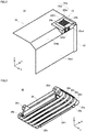
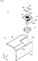
- a workpiece conveying apparatus 10 of the present embodiment is configured by a table 12, a guide member 14, and a belt drive mechanism 16.
- the table 12 is arranged upstream in a work conveyance direction and the guide member 14 is arranged downstream in the work conveyance direction.
- the belt drive mechanism 16 is arranged above the table 12 and the guide member 14 so as to stride over the table 12 and the guide member 14.
- sheet-form workpieces 44, 44, ... like paper (see Fig. 6 ) is mounted in a stacked state.
- a main surface of the mounted workpiece 44 is formed in a rectangular shape, and a longer side of the rectangular shape extends along a sheet conveying direction.
- an X axis, a Y axis, and a Z axis are assigned to a length direction, a width direction, and a thickness direction of the thus mounted workpiece 44, respectively.
- a positive side in an X-axis direction corresponds to the upstream in the workpiece conveyance direction and a negative side in the X-axis direction corresponds to the downstream in the workpiece conveyance direction.
- the positive side in a Z-axis direction corresponds to an upward direction and a negative side in the Z-axis direction corresponds to a downward direction.
- the guide member 14 includes a base plate 18, a blower stay 22 attached to the base plate 18, and a blower 20 held by the blower stay 22.
- the base plate 18 has an upper surface 18tp which assists conveyance of the workpiece 44 by the belt drive mechanism 16, a side surface (wall surface) 18sd which regulates a positional displacement of the workpieces 44, 44, ... stacked on the table 12, and further includes a slope 18slp which is provided at a position connecting the upper surface 18tp and the side surface 18sd to cancel a deflection of the workpiece 44 during conveyance.
- the base plate 18 is also formed with a cutout portion 18ct which partially cuts out the upper surface 18tp, the slope 18slp, and the side surface 18sd at an end portion at the positive side in a Y-axis direction.
- the blower 20 and the blower stay 22 holding the blower 20 are fit into this cutout portion 18ct.
- the blower stay 22 also has an upper surface 22tp and a side surface 22sd. In a state of being fit into the cutout portion 18ct, the upper surface 22tp is flush with the upper surface 18tp and the side surface 22sd is substantially flush with the side surface 18sd.
- An upper surface 14tp of the guide member 14 (see Fig. 2 ) is formed by the upper surfaces 22tp and 18tp.
- a second opening portion OP2 is formed on the upper surface 22tp and a third opening portion OP3 is formed on the side surface 22sd.
- the second opening portion OP2 is formed of a plurality of through holes which extend linearly in the X-axis direction and are arrayed in the Y-axis direction.
- the blower 20 generates a downward suction force in the second opening portion OP2 to ensure that the workpiece 44 being conveyed adheres to the upper surface 22tp.
- a part of air suctioned through the second opening portion OP2 is exhausted from the third opening portion OP3.
- the workpieces 44, 44, ... stacked on the table 12 are separated by the air exhausted from the third opening portion OP3.
- Strip-like friction materials (urethane plates) 24a and 24b are also affixed to the upper surface 22tp.
- the friction material 24a extends along the X axis on a negative-side position in the Y-axis direction relative to the second opening portion OP22
- the friction material 24b extends along the X axis on a positive-side position in the Y-axis direction relative to the second opening portion OP22.
- the positional displacement of the workpiece 44 adhering to the upper surface 22tp is suppressed by the friction materials 24a and 24b affixed in this manner.
- a workpiece alignment 42 is affixed on the side surface 18sd.
- the workpiece alignment 42 is a member which aligns the workpieces 44, 44, ... stacked on the table 12 and extends a positive-side end portion in the Y-axis direction into the Z-axis direction.
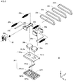
- the belt drive mechanism 16 includes pulley holders 30a and 30b arranged with a spacing therebetween in the X-axis direction.
- the pulley holder 30a is arranged on the positive side in the X-axis direction and the pulley holder 30b is arranged on the negative side in the X-axis direction.
- an arrangement in each of the Y-axis direction and the Z-axis direction matches between the pulley holders 30a and 30b.
- Each rotational axis of the held large diameter pulleys 26a to 26d and the small diameter pulleys 28a and 28b extends along the Y axis. Furthermore, an arrangement in the Z-axis direction (height direction) matches between the large diameter pulleys 26a and 26b, matches between the large diameter pulleys 26c and 26d, and matches between the small diameter pulleys 28a and 28b.
- the large diameter pulleys 26c and 26d are arranged at a higher position than the large diameter pulleys 26a and 26b, and the small diameter pulleys 28a and 28b are arranged at a slightly lower position than the large diameter pulleys 26a and 26b.
- a case 34 is configured by an upper-side case member 34up having a ceiling surface on which through holes HL1a and HL1b are formed, a bottom-side case member 34btm having a bottom surface on which the first opening portion OP1 is formed, and a partition plate 34sp housed in the bottom-side case member 34btm.
- the through holes HL1a and HL1b are common in size and arrayed in the X-axis direction.
- the through hole HL1a is arranged on the positive side in the X-axis direction and the through hole HL1b is arranged on the negative side in the X-axis direction.
- the partition plate 34sp is arranged on the bottom-side case member 34btm so as to extend, along the Y axis, between the through holes HL1a and HL1b. As a result, an inner space of the case 34 is partitioned into a space SPla beneath the through hole HL1a and a space SPlb beneath the through hole HL1b.
- the first opening portion OP1 includes a plurality of through holes linearly extending in the X-axis direction and arrayed in the Y-axis direction. A width of each through hole is larger in the upstream (the space SP1a side) of the partition plate 34sp and narrower in the downstream (the space SP1b side) of the partition plate 34sp.
- a blower 36a is arranged on the ceiling surface of the upper-side case member 36up so as to cover the through hole HL1a. Furthermore, a blower 36b has the same size and capability as the blower 36a and is arranged on the ceiling surface of the upper-side case member 34up so as to cover the through hole HL1b.
- the blowers 36a and 36b arranged in such a way generate the upward suction force in the first opening portion OP1.
- the upward suction force generated in the first opening portion OP1 exceeds the downward suction force generated in the second opening portion OP2. Furthermore, as illustrated in Fig. 6 , the downstream end of the first opening portion OP1 is arranged downstream of the second opening portion OP2. More precisely, the downstream end of the first opening portion OP1 is arranged downstream of the both downstream end and upstream end of the second opening portion OP2. Furthermore, a distance from the downstream end of the second opening portion OP2 to the upstream end of the first opening portion OP1 is less than a length from a leading end to a tailing end of the workpiece 44.
- a height size of the case 34 is equal to or less than half a height size of each of the pulley holders 30a and 30b, and a height size of each of the blowers 36a and 36b is also equal to or less than half a height size of each of the pulley holders 30a and 30b. Furthermore, a width of the case 34 is slightly less than each width of the pulley holders 30a and 30b, and a length of the case 34 is slightly less than a spacing between the small diameter pulleys 28a and 28b.
- the case 34, and the blowers 36a and 36b are arranged between the pulley holders 30a and 30b so that a height position of the bottom surface of the bottom-side case member 34btm matches a height position of the lower end of the pulley holders 30a and 30b.
- the case 34 is interposed between the small diameter pulleys 28a and 28b, and further interposed between the large diameter pulleys 26a and 26b.
- the height position of the upper surface of each of the blowers 36a and 36b is lower than the height position of the upper surface of the pulley holders 30a and 30b.
- the endless belts 32a to 32d are wound around the large diameter pulleys 26a to 26d and the small diameter pulleys 28a and 28b.
- the wound endless belts 32a to 32d are arrayed in an order of "32a”, “32b”, “32c”, and "32d” as viewed from the negative side to the positive side in the Y-axis direction.
- the case 34, and the blowers 36a and 36b are housed inside the endless belts 32a to 32d wound in this manner.
- a motor unit 38 having a drive motor 38m is also attached to the pulley holder 30b.
- the drive motor 38m rotates the large diameter pulley 26b in a clockwise direction as viewed from the negative side in the Y-axis direction.
- the endless belts 32a to 32d rotate in the same direction.
- a distance from the workpiece 44 of a top layer mounted on the table 12 to the bottom surface of the belt drive mechanism 16 is detected by a sensor 40 provided in a proximity of the large diameter pulley 26a.
- the table 12 moves up and down so that a detected distance indicates a designated value. That is, the table 12 gradually ascends each time the workpiece 44 is conveyed out.
- the upward suction force is generated in the first opening portion OP1, and thus, the workpiece 44 of the top layer adheres to the endless belts 32a to 32d and is conveyed downstream. Furthermore, the upward suction force generated in the first opening portion OP1 exceeds the downward suction force generated in the second opening portion OP2, and thus, the workpiece 44 adhering to the endless belts 32a to 32d reaches the small diameter pulley 28b without contacting with the upper surface 14tp of the guide member 14, and then, is conveyed downstream on the upper surface 14tp of the guide member 14.
- a conveyance roller 46 is provided at a position downstream of the belt drive mechanism 16. When the leading end of the workpiece 44 reaches the conveyance roller 46, the workpiece 44 is wound up by the conveyance roller 46 and is conveyed further downstream.
- the positional relationship between the workpiece 44 being conveyed and the conveyance roller 46 is detected by a sensor 48 provided downstream of the conveyance roller 46, and the drive motor 38m intermittently rotates the large diameter pulley 26b, based on a detection result of the sensor 48. That is, a rotation of the endless belts 32a to 32d stops immediately after a leading edge of the workpiece 44 has passed through the conveyance roller 46 and resumes immediately after a trail edge of the workpiece 44 has been departed from the conveyance roller 46. As a result, on the average, a peripheral velocity of the large diameter pulley 26b, by extension, the endless belts 32a to 32d, is less than a peripheral velocity of the conveyance roller 46.
- the second workpiece 44 is attached to the first workpiece 44 by a static electricity, for example, and the two workpieces 44 and 44 are multi-fed.
- the first workpiece 44 reaches the downstream end of the first opening portion OP1 and is further conveyed downstream on the upper surface 14tp of the guide member 14, the second workpiece 44 adheres to the guide member 14 by the suction force generated in the second opening portion OP2.
- the second workpiece 44 adhering to the guide member 14 adheres to the bottom surface of the belt drive mechanism 16 at a timing for canceling the multi-feed with the first workpiece 44, and is conveyed downstream by the endless belts 32a to 32d. Therefore, the workpiece 44 is supplied to the conveyance roller 46 one by one even if the two workpieces 44 and 44 are overlapped and conveyed out from the table 12.
- the sheet-form workpieces 44, 44, ... are mounted in a stacked state on the table 12.
- the guide member 14 has the upper surface 14tp assisting conveyance of the workpiece 44 and is arranged downstream of the table 12 in the workpiece conveyance direction.
- the belt drive mechanism 16 has the large diameter pulleys 26a to 26d and the small diameter pulleys 28a and 28b each extending in the direction orthogonal both to the workpiece conveyance direction and the up-and-down direction, and the endless belts 32a to 32d wound around these pulleys, and is arranged above the table 12 and the guide member 14 so as to stride over the table 12 and the guide member 14.
- the first opening portion OP1 is formed on the bottom portion of the belt drive mechanism 16 to generate the upward suction force.
- the second opening portion OP2 is formed on the upper surface 14tp of the guide member 14 to generate the downward suction force.
- the magnitude of the suction force generated in the first opening portion OP1 exceeds the magnitude of the suction force generated in the second opening portion OP2.
- the workpiece 44 mounted on the table 12 adheres to the bottom portion of the belt drive mechanism 16 at the upstream end of the first opening portion OP1 and is conveyed downstream by the endless belts 32a to 32d.
- the adhering workpiece 44 reaches the downstream end of the first opening portion OP1, the workpiece 44 departs from the belt drive mechanism 16 and is further conveyed downstream along the upper surface 14tp of the guide member 14.
- the first workpiece 44 reaches the downstream end of the first opening portion OP1, and is further conveyed downstream on the upper surface 14tp of the guide member 14.
- the second workpiece 44 adheres to the guide member 14 by the suction force generated in the second opening portion OP2.
- the second workpiece 44 adhering to the guide member 14 adheres to the bottom portion of the belt drive mechanism 16 at a timing for canceling the multi-feed with the first workpiece 44, and is conveyed downstream by the endless belts 32a to 32d. As a result, it is possible to convey the workpiece 44 one by one without receiving assistance from an operator during operation.
- downstream end of the first opening portion OP1 is arranged downstream of the downstream end of the second opening portion OP2. As a result, it is possible to ensure that the second multi-fed workpiece 44 adheres to the guide member 14.
- the distance from the downstream end of the second opening portion OP2 to the upstream end of the first opening portion OP1 is set to be shorter than the length from the leading end to the tailing end of the workpiece 44.
- the first opening portion OP1 is formed on the bottom surface of the bottom-side case member 34btm, it may be possible that the case 34 is omitted and the endless belts 32a to 32d is replaced by a single endless belt having a countless number of through holes.
Landscapes
- Engineering & Computer Science (AREA)
- Mechanical Engineering (AREA)
- Delivering By Means Of Belts And Rollers (AREA)
- Sheets, Magazines, And Separation Thereof (AREA)
Claims (5)
- Werkstück-Fördereinrichtung (10), umfassend:einen Tisch (12), auf dem blechförmige Werkstücke (44) in einem gestapelten Zustand angebracht sind;ein Führungselement (14), das eine obere Oberfläche (14tp) aufweist, die eine Beförderung der Werkstücke unterstützt, und das stromabwärts von dem Tisch in einer Werkstück-Förderrichtung angeordnet ist; undeinen Riemenantriebsmechanismus (16), der eine Vielzahl von Rollen (26a∼26d, 28a∼28b) aufweist, die sich jeweils in einer Richtung orthogonal zu sowohl der Werkstück-Förderrichtung als auch einer Auf-Ab-Richtung erstrecken, und einen Endlosriemen (32a∼32d), der um die Vielzahl von Rollen gewickelt ist, und der über dem Tisch und dem Führungselement angeordnet ist, um über den Tisch und das Führungselement zu laufen, wobeiein erster Öffnungsabschnitt (OP1), der eine erste Aufwärtssaugkraft erzeugt, auf einem unteren Abschnitt des Riemenantriebsmechanismus gebildet ist,ein zweiter Öffnungsabschnitt (OP2), der eine zweite Abwärtssaugkraft erzeugt, auf der oberen Oberfläche des Führungselements gebildet ist, undeine Stärke der ersten Saugkraft eine Stärke der zweiten Saugkraft übersteigt, dadurch gekennzeichnet, dassein Reibungsmaterial (24a, 24b) an der oberen Oberfläche des Führungselements fixiert ist, um eine Positionsverschiebung des Werkstücks, das an der oberen Oberfläche anhaftet, zu unterdrücken,das Reibungsmaterial ein erstes Reibungsmaterial (24a) und ein zweites Reibungsmaterial (24b) umfasst, die an Positionen bereitgestellt sind, welche den zweiten Öffnungsabschnitt in einer Richtung orthogonal zu der Werkstück-Förderrichtung einschichten, undjedes des ersten Reibungsmaterials und des zweiten Reibungsmaterials ein streifenähnliches Material ist, das sich entlang der Werkstück-Förderrichtung erstreckt.
- Werkstück-Fördereinrichtung nach Anspruch 1, wobei ein stromabwärtiges Ende des zweiten Öffnungsabschnitts stromaufwärts von einem stromabwärtigen Ende des ersten Öffnungsabschnitts angeordnet ist.
- Werkstück-Fördereinrichtung nach Anspruch 1 oder 2, wobei ein Abstand von dem stromabwärtigen Ende des zweiten Öffnungsabschnitts zu einem stromaufwärtigen Ende des ersten Öffnungsabschnitts kürzer ist als eine Länge von einem vorderen Ende des Werkstücks zu dessen hinterem Ende.
- Werkstück-Fördereinrichtung nach einem der Ansprüche 1 bis 3, wobei der Riemenantriebsmechanismus weiter einen Motor (38m) umfasst, der die Vielzahl von Rollen bei einer Umfangsgeschwindigkeit dreht, die geringer ist als eine Umfangsgeschwindigkeit einer Förderwalze (46), die stromabwärts von dem Führungselement angeordnet ist.
- Werkstück-Fördereinrichtung nach Anspruch 4, wobei der Motor die Vielzahl von Rollen intermittierend dreht, basierend auf einem Positionsverhältnis zwischen einem Werkstück, das von dem Riemenantriebsmechanismus befördert wird, und der Förderwalze.
Applications Claiming Priority (2)
| Application Number | Priority Date | Filing Date | Title |
|---|---|---|---|
| JP2015206079A JP7082455B2 (ja) | 2015-10-20 | 2015-10-20 | ワーク搬送装置 |
| PCT/JP2016/079983 WO2017069006A1 (ja) | 2015-10-20 | 2016-10-07 | ワーク搬送装置 |
Publications (3)
| Publication Number | Publication Date |
|---|---|
| EP3366620A1 EP3366620A1 (de) | 2018-08-29 |
| EP3366620A4 EP3366620A4 (de) | 2019-06-26 |
| EP3366620B1 true EP3366620B1 (de) | 2021-01-13 |
Family
ID=58557487
Family Applications (1)
| Application Number | Title | Priority Date | Filing Date |
|---|---|---|---|
| EP16857321.0A Active EP3366620B1 (de) | 2015-10-20 | 2016-10-07 | Vorrichtung zur förderung von werkstücken |
Country Status (5)
| Country | Link |
|---|---|
| US (1) | US10308455B2 (de) |
| EP (1) | EP3366620B1 (de) |
| JP (1) | JP7082455B2 (de) |
| CN (1) | CN108602636B (de) |
| WO (1) | WO2017069006A1 (de) |
Families Citing this family (1)
| Publication number | Priority date | Publication date | Assignee | Title |
|---|---|---|---|---|
| JP7135682B2 (ja) * | 2018-09-28 | 2022-09-13 | 株式会社リコー | 給送装置、画像形成装置及び画像形成システム |
Family Cites Families (13)
| Publication number | Priority date | Publication date | Assignee | Title |
|---|---|---|---|---|
| US3260520A (en) * | 1964-03-09 | 1966-07-12 | Gen Electric | Document handling apparatus |
| JPS5926455U (ja) * | 1982-08-13 | 1984-02-18 | 株式会社東芝 | 紙葉類の取出装置 |
| JPH0688678B2 (ja) * | 1985-12-13 | 1994-11-09 | シャープ株式会社 | シ−ト材の重送防止装置 |
| DE3710258A1 (de) * | 1987-03-28 | 1988-10-13 | Heidelberger Druckmasch Ag | Vorrichtung zum transport von bogen, beispielsweise papierbogen |
| GB2276871B (en) * | 1993-04-07 | 1997-04-23 | Licentia Gmbh | Method of and apparatus for separately removing flat articles from a stack |
| JP4775046B2 (ja) * | 2006-03-15 | 2011-09-21 | コニカミノルタビジネステクノロジーズ株式会社 | 用紙搬送装置及び画像形成装置 |
| JP2007331944A (ja) * | 2006-05-15 | 2007-12-27 | Canon Inc | シート給送装置及び画像形成装置 |
| JP2011042470A (ja) * | 2009-08-21 | 2011-03-03 | Canon Inc | シート給送装置及び画像形成装置 |
| JP5494150B2 (ja) * | 2009-12-10 | 2014-05-14 | コニカミノルタ株式会社 | 給紙装置及び画像形成システム |
| US9079733B2 (en) * | 2010-05-07 | 2015-07-14 | Bdt Media Automation Gmbh | Vortex suction separator device |
| JP5718621B2 (ja) | 2010-11-19 | 2015-05-13 | キヤノン電子株式会社 | シート搬送装置及び情報読取装置 |
| US9181050B2 (en) | 2010-11-10 | 2015-11-10 | Canon Denshi Kabushiki Kaisha | Sheet feeding apparatus, control method thereof, and document reading apparatus |
| JP6443733B2 (ja) * | 2014-11-04 | 2018-12-26 | 株式会社リコー | 給紙装置、画像形成装置および画像形成システム |
-
2015
- 2015-10-20 JP JP2015206079A patent/JP7082455B2/ja active Active
-
2016
- 2016-10-07 CN CN201680061785.0A patent/CN108602636B/zh active Active
- 2016-10-07 EP EP16857321.0A patent/EP3366620B1/de active Active
- 2016-10-07 US US15/765,332 patent/US10308455B2/en active Active
- 2016-10-07 WO PCT/JP2016/079983 patent/WO2017069006A1/ja not_active Ceased
Non-Patent Citations (1)
| Title |
|---|
| None * |
Also Published As
| Publication number | Publication date |
|---|---|
| EP3366620A1 (de) | 2018-08-29 |
| US20180305148A1 (en) | 2018-10-25 |
| EP3366620A4 (de) | 2019-06-26 |
| CN108602636B (zh) | 2020-11-17 |
| CN108602636A (zh) | 2018-09-28 |
| WO2017069006A1 (ja) | 2017-04-27 |
| JP2017077938A (ja) | 2017-04-27 |
| JP7082455B2 (ja) | 2022-06-08 |
| US10308455B2 (en) | 2019-06-04 |
Similar Documents
| Publication | Publication Date | Title |
|---|---|---|
| EP3533732B1 (de) | Druckvorrichtung für pharmazeutische präparate | |
| JP7204284B2 (ja) | 媒体供給装置 | |
| US10308455B2 (en) | Workpiece conveying apparatus | |
| US8387968B2 (en) | Recording-material-feeding device and image forming apparatus | |
| JP2011246204A (ja) | 給紙装置及び画像形成システム | |
| RU2613223C2 (ru) | Устройство выталкивания и отделения листов и устройство обработки листов | |
| JP2024027194A (ja) | 袋供給装置 | |
| US20180009614A1 (en) | Sheet feeding device and image forming apparatus | |
| WO2014002942A1 (ja) | 処理装置および画像形成装置 | |
| JP5440301B2 (ja) | 画像形成装置 | |
| KR20180001319A (ko) | 홈 커팅 장치 | |
| JP6430174B2 (ja) | 紙葉類取出装置および紙葉類処理装置 | |
| JP2023111725A (ja) | 袋搬送システム | |
| JP2006016159A (ja) | エアー吸着方式給紙装置 | |
| JP6559962B2 (ja) | 姿勢転換機構、および、これを備える箱詰め装置 | |
| JPH034463B2 (de) | ||
| JP4789262B2 (ja) | 給紙装置 | |
| JP2020015610A (ja) | 用紙排出装置 | |
| JP5357453B2 (ja) | 丁合搬送装置 | |
| JP2006143399A (ja) | 給紙装置 | |
| JPH02133124A (ja) | プレス機械の加工材料供給装置 | |
| JP2023163622A (ja) | 物品支持台、供給装置及び画像形成装置 | |
| JP2023048760A (ja) | 搬送システム | |
| JP2010241589A (ja) | エア吸引給紙装置、およびこのエア吸引給紙装置を有する画像形成装置 | |
| JP2007091431A (ja) | シート収容ケースおよびシート供給装置 |
Legal Events
| Date | Code | Title | Description |
|---|---|---|---|
| STAA | Information on the status of an ep patent application or granted ep patent |
Free format text: STATUS: THE INTERNATIONAL PUBLICATION HAS BEEN MADE |
|
| PUAI | Public reference made under article 153(3) epc to a published international application that has entered the european phase |
Free format text: ORIGINAL CODE: 0009012 |
|
| STAA | Information on the status of an ep patent application or granted ep patent |
Free format text: STATUS: REQUEST FOR EXAMINATION WAS MADE |
|
| 17P | Request for examination filed |
Effective date: 20180417 |
|
| AK | Designated contracting states |
Kind code of ref document: A1 Designated state(s): AL AT BE BG CH CY CZ DE DK EE ES FI FR GB GR HR HU IE IS IT LI LT LU LV MC MK MT NL NO PL PT RO RS SE SI SK SM TR |
|
| AX | Request for extension of the european patent |
Extension state: BA ME |
|
| DAV | Request for validation of the european patent (deleted) | ||
| DAX | Request for extension of the european patent (deleted) | ||
| A4 | Supplementary search report drawn up and despatched |
Effective date: 20190528 |
|
| RIC1 | Information provided on ipc code assigned before grant |
Ipc: B65H 3/48 20060101ALI20190522BHEP Ipc: B65H 3/12 20060101AFI20190522BHEP Ipc: B65H 3/64 20060101ALI20190522BHEP Ipc: B65H 3/52 20060101ALI20190522BHEP |
|
| STAA | Information on the status of an ep patent application or granted ep patent |
Free format text: STATUS: EXAMINATION IS IN PROGRESS |
|
| 17Q | First examination report despatched |
Effective date: 20191104 |
|
| GRAP | Despatch of communication of intention to grant a patent |
Free format text: ORIGINAL CODE: EPIDOSNIGR1 |
|
| STAA | Information on the status of an ep patent application or granted ep patent |
Free format text: STATUS: GRANT OF PATENT IS INTENDED |
|
| INTG | Intention to grant announced |
Effective date: 20200813 |
|
| GRAS | Grant fee paid |
Free format text: ORIGINAL CODE: EPIDOSNIGR3 |
|
| GRAA | (expected) grant |
Free format text: ORIGINAL CODE: 0009210 |
|
| STAA | Information on the status of an ep patent application or granted ep patent |
Free format text: STATUS: THE PATENT HAS BEEN GRANTED |
|
| AK | Designated contracting states |
Kind code of ref document: B1 Designated state(s): AL AT BE BG CH CY CZ DE DK EE ES FI FR GB GR HR HU IE IS IT LI LT LU LV MC MK MT NL NO PL PT RO RS SE SI SK SM TR |
|
| REG | Reference to a national code |
Ref country code: GB Ref legal event code: FG4D |
|
| REG | Reference to a national code |
Ref country code: CH Ref legal event code: EP |
|
| REG | Reference to a national code |
Ref country code: IE Ref legal event code: FG4D |
|
| REG | Reference to a national code |
Ref country code: DE Ref legal event code: R096 Ref document number: 602016051511 Country of ref document: DE |
|
| REG | Reference to a national code |
Ref country code: AT Ref legal event code: REF Ref document number: 1354412 Country of ref document: AT Kind code of ref document: T Effective date: 20210215 |
|
| REG | Reference to a national code |
Ref country code: SE Ref legal event code: TRGR |
|
| REG | Reference to a national code |
Ref country code: NL Ref legal event code: FP |
|
| RAP2 | Party data changed (patent owner data changed or rights of a patent transferred) |
Owner name: UCHIDA YOKO GLOBAL CO., LTD. Owner name: SAKURA SEIKI CO., LTD. Owner name: UCHIDA YOKO CO., LTD. |
|
| REG | Reference to a national code |
Ref country code: DE Ref legal event code: R082 Ref document number: 602016051511 Country of ref document: DE Representative=s name: HOFFMANN - EITLE PATENT- UND RECHTSANWAELTE PA, DE Ref country code: DE Ref legal event code: R081 Ref document number: 602016051511 Country of ref document: DE Owner name: UCHIDA YOKO GLOBAL CO., LTD., JP Free format text: FORMER OWNERS: SAKURA SEIKI CO., LTD., YAO-SHI, OSAKA, JP; UCHIDA YOKO CO., LTD., TOKIO/TOKYO, JP; UCHIDA YOKO GLOBAL LIMITED, HONG KONG, HK Ref country code: DE Ref legal event code: R081 Ref document number: 602016051511 Country of ref document: DE Owner name: UCHIDA YOKO CO., LTD., JP Free format text: FORMER OWNERS: SAKURA SEIKI CO., LTD., YAO-SHI, OSAKA, JP; UCHIDA YOKO CO., LTD., TOKIO/TOKYO, JP; UCHIDA YOKO GLOBAL LIMITED, HONG KONG, HK Ref country code: DE Ref legal event code: R081 Ref document number: 602016051511 Country of ref document: DE Owner name: SAKURA SEIKI CO., LTD., YAO-SHI, JP Free format text: FORMER OWNERS: SAKURA SEIKI CO., LTD., YAO-SHI, OSAKA, JP; UCHIDA YOKO CO., LTD., TOKIO/TOKYO, JP; UCHIDA YOKO GLOBAL LIMITED, HONG KONG, HK |
|
| REG | Reference to a national code |
Ref country code: AT Ref legal event code: MK05 Ref document number: 1354412 Country of ref document: AT Kind code of ref document: T Effective date: 20210113 |
|
| REG | Reference to a national code |
Ref country code: NL Ref legal event code: PD Owner name: UCHIDA YOKO GLOBAL CO., LTD.; JP Free format text: DETAILS ASSIGNMENT: CHANGE OF OWNER(S), ASSIGNMENT; FORMER OWNER NAME: UCHIDA YOKO GLOBAL LIMITED Effective date: 20210510 |
|
| REG | Reference to a national code |
Ref country code: GB Ref legal event code: 732E Free format text: REGISTERED BETWEEN 20210603 AND 20210609 |
|
| REG | Reference to a national code |
Ref country code: LT Ref legal event code: MG9D |
|
| PG25 | Lapsed in a contracting state [announced via postgrant information from national office to epo] |
Ref country code: GR Free format text: LAPSE BECAUSE OF FAILURE TO SUBMIT A TRANSLATION OF THE DESCRIPTION OR TO PAY THE FEE WITHIN THE PRESCRIBED TIME-LIMIT Effective date: 20210414 Ref country code: HR Free format text: LAPSE BECAUSE OF FAILURE TO SUBMIT A TRANSLATION OF THE DESCRIPTION OR TO PAY THE FEE WITHIN THE PRESCRIBED TIME-LIMIT Effective date: 20210113 Ref country code: FI Free format text: LAPSE BECAUSE OF FAILURE TO SUBMIT A TRANSLATION OF THE DESCRIPTION OR TO PAY THE FEE WITHIN THE PRESCRIBED TIME-LIMIT Effective date: 20210113 Ref country code: PT Free format text: LAPSE BECAUSE OF FAILURE TO SUBMIT A TRANSLATION OF THE DESCRIPTION OR TO PAY THE FEE WITHIN THE PRESCRIBED TIME-LIMIT Effective date: 20210513 Ref country code: NO Free format text: LAPSE BECAUSE OF FAILURE TO SUBMIT A TRANSLATION OF THE DESCRIPTION OR TO PAY THE FEE WITHIN THE PRESCRIBED TIME-LIMIT Effective date: 20210413 Ref country code: BG Free format text: LAPSE BECAUSE OF FAILURE TO SUBMIT A TRANSLATION OF THE DESCRIPTION OR TO PAY THE FEE WITHIN THE PRESCRIBED TIME-LIMIT Effective date: 20210413 Ref country code: LT Free format text: LAPSE BECAUSE OF FAILURE TO SUBMIT A TRANSLATION OF THE DESCRIPTION OR TO PAY THE FEE WITHIN THE PRESCRIBED TIME-LIMIT Effective date: 20210113 |
|
| PG25 | Lapsed in a contracting state [announced via postgrant information from national office to epo] |
Ref country code: AT Free format text: LAPSE BECAUSE OF FAILURE TO SUBMIT A TRANSLATION OF THE DESCRIPTION OR TO PAY THE FEE WITHIN THE PRESCRIBED TIME-LIMIT Effective date: 20210113 Ref country code: PL Free format text: LAPSE BECAUSE OF FAILURE TO SUBMIT A TRANSLATION OF THE DESCRIPTION OR TO PAY THE FEE WITHIN THE PRESCRIBED TIME-LIMIT Effective date: 20210113 Ref country code: RS Free format text: LAPSE BECAUSE OF FAILURE TO SUBMIT A TRANSLATION OF THE DESCRIPTION OR TO PAY THE FEE WITHIN THE PRESCRIBED TIME-LIMIT Effective date: 20210113 Ref country code: LV Free format text: LAPSE BECAUSE OF FAILURE TO SUBMIT A TRANSLATION OF THE DESCRIPTION OR TO PAY THE FEE WITHIN THE PRESCRIBED TIME-LIMIT Effective date: 20210113 |
|
| PG25 | Lapsed in a contracting state [announced via postgrant information from national office to epo] |
Ref country code: IS Free format text: LAPSE BECAUSE OF FAILURE TO SUBMIT A TRANSLATION OF THE DESCRIPTION OR TO PAY THE FEE WITHIN THE PRESCRIBED TIME-LIMIT Effective date: 20210513 |
|
| REG | Reference to a national code |
Ref country code: DE Ref legal event code: R097 Ref document number: 602016051511 Country of ref document: DE |
|
| PG25 | Lapsed in a contracting state [announced via postgrant information from national office to epo] |
Ref country code: SM Free format text: LAPSE BECAUSE OF FAILURE TO SUBMIT A TRANSLATION OF THE DESCRIPTION OR TO PAY THE FEE WITHIN THE PRESCRIBED TIME-LIMIT Effective date: 20210113 Ref country code: CZ Free format text: LAPSE BECAUSE OF FAILURE TO SUBMIT A TRANSLATION OF THE DESCRIPTION OR TO PAY THE FEE WITHIN THE PRESCRIBED TIME-LIMIT Effective date: 20210113 Ref country code: EE Free format text: LAPSE BECAUSE OF FAILURE TO SUBMIT A TRANSLATION OF THE DESCRIPTION OR TO PAY THE FEE WITHIN THE PRESCRIBED TIME-LIMIT Effective date: 20210113 |
|
| PLBE | No opposition filed within time limit |
Free format text: ORIGINAL CODE: 0009261 |
|
| STAA | Information on the status of an ep patent application or granted ep patent |
Free format text: STATUS: NO OPPOSITION FILED WITHIN TIME LIMIT |
|
| PG25 | Lapsed in a contracting state [announced via postgrant information from national office to epo] |
Ref country code: RO Free format text: LAPSE BECAUSE OF FAILURE TO SUBMIT A TRANSLATION OF THE DESCRIPTION OR TO PAY THE FEE WITHIN THE PRESCRIBED TIME-LIMIT Effective date: 20210113 Ref country code: SK Free format text: LAPSE BECAUSE OF FAILURE TO SUBMIT A TRANSLATION OF THE DESCRIPTION OR TO PAY THE FEE WITHIN THE PRESCRIBED TIME-LIMIT Effective date: 20210113 Ref country code: DK Free format text: LAPSE BECAUSE OF FAILURE TO SUBMIT A TRANSLATION OF THE DESCRIPTION OR TO PAY THE FEE WITHIN THE PRESCRIBED TIME-LIMIT Effective date: 20210113 |
|
| 26N | No opposition filed |
Effective date: 20211014 |
|
| PG25 | Lapsed in a contracting state [announced via postgrant information from national office to epo] |
Ref country code: AL Free format text: LAPSE BECAUSE OF FAILURE TO SUBMIT A TRANSLATION OF THE DESCRIPTION OR TO PAY THE FEE WITHIN THE PRESCRIBED TIME-LIMIT Effective date: 20210113 Ref country code: ES Free format text: LAPSE BECAUSE OF FAILURE TO SUBMIT A TRANSLATION OF THE DESCRIPTION OR TO PAY THE FEE WITHIN THE PRESCRIBED TIME-LIMIT Effective date: 20210113 |
|
| PG25 | Lapsed in a contracting state [announced via postgrant information from national office to epo] |
Ref country code: SI Free format text: LAPSE BECAUSE OF FAILURE TO SUBMIT A TRANSLATION OF THE DESCRIPTION OR TO PAY THE FEE WITHIN THE PRESCRIBED TIME-LIMIT Effective date: 20210113 |
|
| PG25 | Lapsed in a contracting state [announced via postgrant information from national office to epo] |
Ref country code: IT Free format text: LAPSE BECAUSE OF FAILURE TO SUBMIT A TRANSLATION OF THE DESCRIPTION OR TO PAY THE FEE WITHIN THE PRESCRIBED TIME-LIMIT Effective date: 20210113 |
|
| REG | Reference to a national code |
Ref country code: CH Ref legal event code: PL |
|
| PG25 | Lapsed in a contracting state [announced via postgrant information from national office to epo] |
Ref country code: IS Free format text: LAPSE BECAUSE OF FAILURE TO SUBMIT A TRANSLATION OF THE DESCRIPTION OR TO PAY THE FEE WITHIN THE PRESCRIBED TIME-LIMIT Effective date: 20210513 |
|
| REG | Reference to a national code |
Ref country code: BE Ref legal event code: MM Effective date: 20211031 |
|
| PG25 | Lapsed in a contracting state [announced via postgrant information from national office to epo] |
Ref country code: MC Free format text: LAPSE BECAUSE OF FAILURE TO SUBMIT A TRANSLATION OF THE DESCRIPTION OR TO PAY THE FEE WITHIN THE PRESCRIBED TIME-LIMIT Effective date: 20210113 |
|
| PG25 | Lapsed in a contracting state [announced via postgrant information from national office to epo] |
Ref country code: LU Free format text: LAPSE BECAUSE OF NON-PAYMENT OF DUE FEES Effective date: 20211007 Ref country code: BE Free format text: LAPSE BECAUSE OF NON-PAYMENT OF DUE FEES Effective date: 20211031 |
|
| PG25 | Lapsed in a contracting state [announced via postgrant information from national office to epo] |
Ref country code: LI Free format text: LAPSE BECAUSE OF NON-PAYMENT OF DUE FEES Effective date: 20211031 Ref country code: CH Free format text: LAPSE BECAUSE OF NON-PAYMENT OF DUE FEES Effective date: 20211031 |
|
| PG25 | Lapsed in a contracting state [announced via postgrant information from national office to epo] |
Ref country code: IE Free format text: LAPSE BECAUSE OF NON-PAYMENT OF DUE FEES Effective date: 20211007 |
|
| PG25 | Lapsed in a contracting state [announced via postgrant information from national office to epo] |
Ref country code: HU Free format text: LAPSE BECAUSE OF FAILURE TO SUBMIT A TRANSLATION OF THE DESCRIPTION OR TO PAY THE FEE WITHIN THE PRESCRIBED TIME-LIMIT; INVALID AB INITIO Effective date: 20161007 |
|
| P01 | Opt-out of the competence of the unified patent court (upc) registered |
Effective date: 20230517 |
|
| PG25 | Lapsed in a contracting state [announced via postgrant information from national office to epo] |
Ref country code: CY Free format text: LAPSE BECAUSE OF FAILURE TO SUBMIT A TRANSLATION OF THE DESCRIPTION OR TO PAY THE FEE WITHIN THE PRESCRIBED TIME-LIMIT Effective date: 20210113 |
|
| PG25 | Lapsed in a contracting state [announced via postgrant information from national office to epo] |
Ref country code: MK Free format text: LAPSE BECAUSE OF FAILURE TO SUBMIT A TRANSLATION OF THE DESCRIPTION OR TO PAY THE FEE WITHIN THE PRESCRIBED TIME-LIMIT Effective date: 20210113 |
|
| PG25 | Lapsed in a contracting state [announced via postgrant information from national office to epo] |
Ref country code: MT Free format text: LAPSE BECAUSE OF FAILURE TO SUBMIT A TRANSLATION OF THE DESCRIPTION OR TO PAY THE FEE WITHIN THE PRESCRIBED TIME-LIMIT Effective date: 20210113 |
|
| PGFP | Annual fee paid to national office [announced via postgrant information from national office to epo] |
Ref country code: NL Payment date: 20251021 Year of fee payment: 10 |
|
| PG25 | Lapsed in a contracting state [announced via postgrant information from national office to epo] |
Ref country code: TR Free format text: LAPSE BECAUSE OF FAILURE TO SUBMIT A TRANSLATION OF THE DESCRIPTION OR TO PAY THE FEE WITHIN THE PRESCRIBED TIME-LIMIT Effective date: 20210113 |
|
| PGFP | Annual fee paid to national office [announced via postgrant information from national office to epo] |
Ref country code: DE Payment date: 20251021 Year of fee payment: 10 |
|
| PGFP | Annual fee paid to national office [announced via postgrant information from national office to epo] |
Ref country code: GB Payment date: 20251022 Year of fee payment: 10 |
|
| PGFP | Annual fee paid to national office [announced via postgrant information from national office to epo] |
Ref country code: FR Payment date: 20251030 Year of fee payment: 10 |
|
| PGFP | Annual fee paid to national office [announced via postgrant information from national office to epo] |
Ref country code: SE Payment date: 20251021 Year of fee payment: 10 |