EP3364431A2 - Reaktor und verfahren zu seiner herstellung - Google Patents
Reaktor und verfahren zu seiner herstellung Download PDFInfo
- Publication number
- EP3364431A2 EP3364431A2 EP17207999.8A EP17207999A EP3364431A2 EP 3364431 A2 EP3364431 A2 EP 3364431A2 EP 17207999 A EP17207999 A EP 17207999A EP 3364431 A2 EP3364431 A2 EP 3364431A2
- Authority
- EP
- European Patent Office
- Prior art keywords
- leg parts
- coil part
- central leg
- bobbins
- reactor according
- Prior art date
- Legal status (The legal status is an assumption and is not a legal conclusion. Google has not performed a legal analysis and makes no representation as to the accuracy of the status listed.)
- Granted
Links
Images



Classifications
-
- H—ELECTRICITY
- H01—ELECTRIC ELEMENTS
- H01F—MAGNETS; INDUCTANCES; TRANSFORMERS; SELECTION OF MATERIALS FOR THEIR MAGNETIC PROPERTIES
- H01F41/00—Apparatus or processes specially adapted for manufacturing or assembling magnets, inductances or transformers; Apparatus or processes specially adapted for manufacturing materials characterised by their magnetic properties
- H01F41/02—Apparatus or processes specially adapted for manufacturing or assembling magnets, inductances or transformers; Apparatus or processes specially adapted for manufacturing materials characterised by their magnetic properties for manufacturing cores, coils, or magnets
- H01F41/04—Apparatus or processes specially adapted for manufacturing or assembling magnets, inductances or transformers; Apparatus or processes specially adapted for manufacturing materials characterised by their magnetic properties for manufacturing cores, coils, or magnets for manufacturing coils
- H01F41/06—Coil winding
- H01F41/061—Winding flat conductive wires or sheets
-
- H—ELECTRICITY
- H01—ELECTRIC ELEMENTS
- H01F—MAGNETS; INDUCTANCES; TRANSFORMERS; SELECTION OF MATERIALS FOR THEIR MAGNETIC PROPERTIES
- H01F17/00—Fixed inductances of the signal type
- H01F17/04—Fixed inductances of the signal type with magnetic core
-
- H—ELECTRICITY
- H01—ELECTRIC ELEMENTS
- H01F—MAGNETS; INDUCTANCES; TRANSFORMERS; SELECTION OF MATERIALS FOR THEIR MAGNETIC PROPERTIES
- H01F27/00—Details of transformers or inductances, in general
- H01F27/06—Mounting, supporting or suspending transformers, reactors or choke coils not being of the signal type
-
- H—ELECTRICITY
- H01—ELECTRIC ELEMENTS
- H01F—MAGNETS; INDUCTANCES; TRANSFORMERS; SELECTION OF MATERIALS FOR THEIR MAGNETIC PROPERTIES
- H01F27/00—Details of transformers or inductances, in general
- H01F27/08—Cooling; Ventilating
- H01F27/22—Cooling by heat conduction through solid or powdered fillings
-
- H—ELECTRICITY
- H01—ELECTRIC ELEMENTS
- H01F—MAGNETS; INDUCTANCES; TRANSFORMERS; SELECTION OF MATERIALS FOR THEIR MAGNETIC PROPERTIES
- H01F27/00—Details of transformers or inductances, in general
- H01F27/24—Magnetic cores
- H01F27/255—Magnetic cores made from particles
-
- H—ELECTRICITY
- H01—ELECTRIC ELEMENTS
- H01F—MAGNETS; INDUCTANCES; TRANSFORMERS; SELECTION OF MATERIALS FOR THEIR MAGNETIC PROPERTIES
- H01F27/00—Details of transformers or inductances, in general
- H01F27/28—Coils; Windings; Conductive connections
- H01F27/2823—Wires
-
- H—ELECTRICITY
- H01—ELECTRIC ELEMENTS
- H01F—MAGNETS; INDUCTANCES; TRANSFORMERS; SELECTION OF MATERIALS FOR THEIR MAGNETIC PROPERTIES
- H01F27/00—Details of transformers or inductances, in general
- H01F27/28—Coils; Windings; Conductive connections
- H01F27/2847—Sheets; Strips
-
- H—ELECTRICITY
- H01—ELECTRIC ELEMENTS
- H01F—MAGNETS; INDUCTANCES; TRANSFORMERS; SELECTION OF MATERIALS FOR THEIR MAGNETIC PROPERTIES
- H01F27/00—Details of transformers or inductances, in general
- H01F27/28—Coils; Windings; Conductive connections
- H01F27/30—Fastening or clamping coils, windings, or parts thereof together; Fastening or mounting coils or windings on core, casing, or other support
- H01F27/306—Fastening or mounting coils or windings on core, casing or other support
-
- H—ELECTRICITY
- H01—ELECTRIC ELEMENTS
- H01F—MAGNETS; INDUCTANCES; TRANSFORMERS; SELECTION OF MATERIALS FOR THEIR MAGNETIC PROPERTIES
- H01F27/00—Details of transformers or inductances, in general
- H01F27/28—Coils; Windings; Conductive connections
- H01F27/32—Insulating of coils, windings, or parts thereof
-
- H—ELECTRICITY
- H01—ELECTRIC ELEMENTS
- H01F—MAGNETS; INDUCTANCES; TRANSFORMERS; SELECTION OF MATERIALS FOR THEIR MAGNETIC PROPERTIES
- H01F27/00—Details of transformers or inductances, in general
- H01F27/28—Coils; Windings; Conductive connections
- H01F27/32—Insulating of coils, windings, or parts thereof
- H01F27/324—Insulation between coil and core, between different winding sections, around the coil; Other insulation structures
- H01F27/325—Coil bobbins
-
- H—ELECTRICITY
- H01—ELECTRIC ELEMENTS
- H01F—MAGNETS; INDUCTANCES; TRANSFORMERS; SELECTION OF MATERIALS FOR THEIR MAGNETIC PROPERTIES
- H01F27/00—Details of transformers or inductances, in general
- H01F27/42—Circuits specially adapted for the purpose of modifying, or compensating for, electric characteristics of transformers, reactors, or choke coils
-
- H—ELECTRICITY
- H01—ELECTRIC ELEMENTS
- H01F—MAGNETS; INDUCTANCES; TRANSFORMERS; SELECTION OF MATERIALS FOR THEIR MAGNETIC PROPERTIES
- H01F37/00—Fixed inductances not covered by group H01F17/00
-
- H—ELECTRICITY
- H01—ELECTRIC ELEMENTS
- H01F—MAGNETS; INDUCTANCES; TRANSFORMERS; SELECTION OF MATERIALS FOR THEIR MAGNETIC PROPERTIES
- H01F41/00—Apparatus or processes specially adapted for manufacturing or assembling magnets, inductances or transformers; Apparatus or processes specially adapted for manufacturing materials characterised by their magnetic properties
- H01F41/02—Apparatus or processes specially adapted for manufacturing or assembling magnets, inductances or transformers; Apparatus or processes specially adapted for manufacturing materials characterised by their magnetic properties for manufacturing cores, coils, or magnets
- H01F41/04—Apparatus or processes specially adapted for manufacturing or assembling magnets, inductances or transformers; Apparatus or processes specially adapted for manufacturing materials characterised by their magnetic properties for manufacturing cores, coils, or magnets for manufacturing coils
- H01F41/12—Insulating of windings
-
- H—ELECTRICITY
- H01—ELECTRIC ELEMENTS
- H01F—MAGNETS; INDUCTANCES; TRANSFORMERS; SELECTION OF MATERIALS FOR THEIR MAGNETIC PROPERTIES
- H01F17/00—Fixed inductances of the signal type
- H01F17/04—Fixed inductances of the signal type with magnetic core
- H01F17/045—Fixed inductances of the signal type with magnetic core with core of cylindric geometry and coil wound along its longitudinal axis, i.e. rod or drum core
- H01F2017/046—Fixed inductances of the signal type with magnetic core with core of cylindric geometry and coil wound along its longitudinal axis, i.e. rod or drum core helical coil made of flat wire, e.g. with smaller extension of wire cross section in the direction of the longitudinal axis
-
- H—ELECTRICITY
- H01—ELECTRIC ELEMENTS
- H01F—MAGNETS; INDUCTANCES; TRANSFORMERS; SELECTION OF MATERIALS FOR THEIR MAGNETIC PROPERTIES
- H01F17/00—Fixed inductances of the signal type
- H01F17/04—Fixed inductances of the signal type with magnetic core
- H01F2017/048—Fixed inductances of the signal type with magnetic core with encapsulating core, e.g. made of resin and magnetic powder
Definitions
- the present invention relates to a coil component used as a reactor or the like and a method for producing the coil component, and more specifically, to a reactor for a large current application, in which size reduction can be achieved, and a method for producing the same.
- a coil component such as a reactor can generate inductance by being formed into a configuration in which a winding coil is wound around a magnetic core.
- a structure is formed in the reactor, in which a heat sink (water in the case of a water cooled type) is provided below a bottom surface of a coil housing, and the above-described heat generated therein is released to outside through this heat sink, while being cooled.
- a heat sink water in the case of a water cooled type
- heat transfer to the heat sink is designed to be favorable so as to press an outer peripheral portion of a winding coil wound around the magnetic core onto a heat-dissipating sheet (hereinafter, referred to as a heat transfer sheet) attached on a position facing the heat sink through a housing plate (see Patent Documents 1 and 2 below).
- a heat transfer sheet a heat-dissipating sheet
- a reactor various types of materials are known according to use applications from a large capacity material for a transmission system to a communicator component.
- a desire has been expressed for a technology according to which efficiency of heat dissipation can be further improved to come out in order to achieve size reduction with regard to a size of the reactor.
- the coil is formed by multilayer solenoid winding, for example, even if a conducting wire positioned in an outermost periphery is pressed onto the heat transfer sheet, it requires time and is not efficient to transfer, to the heat transfer sheet, the heat generated in an inner periphery in which the heat generation quantity in the coil is large.
- the present invention has been made in view of the above-described circumstances.
- the present invention is contemplated for providing a reactor from which heat generated therein can be efficiently dissipated to an outside of a component, and a method for producing the same.
- the reactor and the method for producing the reactor according to the present invention have the features described below.
- the reactor according the present invention includes:
- the coil part is formed into a trapezoidal shape, in which a lower base on a side abutting on the heat transfer sheet has a length as large as one and a half times or more a length of an upper base in a winding shape of one turn in the coil part, and a minimum of interior angles is 60 degrees or more.
- the coil part is formed into a triangle, a quadrangle or a pentagon in the winding shape of one turn of the coil part, in which a length of a side abutting on the heat transfer sheet is in a maximum length among all sides and a minimum of interior angles is 60 degrees or more.
- a configuration is formed, in which a length of bobbins of the right and left leg parts each is set to be longer than a length of the coil part wound around the central leg parts, in a vertical direction being a direction perpendicular to a plane including the directions of the central leg parts and arranging the right and left leg parts, and when a sealing resin is filled into a space surrounded by the bobbins of the right and left leg parts, the sealing resin filled therein causes no overflow to outside, and the coil part can be wholly covered with the sealing resin.
- the coil part is formed by combining two substantially E-shaped partial cores in such a manner that leading end portions of three leg parts corresponding to each other are faced with each other.
- the right and left leg parts of the partial cores are formed into a shape so as to come along an outer shape of the coil part wound, in a trapezoidal shape in a cross section, around a circumference of the central leg parts.
- the central leg parts are configured, in which a magnetic portion and a spacer portion are alternately arranged in an axial direction.
- the reactor includes an aluminum case in which the bobbins are wholly stored.
- the method for producing the reactor according to the present invention includes:
- the method includes: housing the core part and the coil part in bobbins covering the right and left leg parts; setting the resulting material in an insert molding machine in a state in which the bobbins are wholly stored within a case; filling an inside of the bobbins with an insulating resin agent through a filling hole part; and then applying integral molding processing thereto within a mold.
- winding edgewise or “edgewise winding” means operation of longitudinally winding a rectangular wire with a short side being one side edge of a rectangular wire material as an inner diameter surface.
- the rectangular wire is used as the coil part wound around the circumference of the central leg parts, and therefore the reactor is preferable for passing a large capacity current therethrough. Furthermore, the rectangular wire is wound around the circumference of the central leg parts by edgewise winding, and in each turn of the coil part, an inner periphery and an outer periphery are formed as one side edge and the other side edge of the same rectangular wire material, respectively. Therefore, heat can be quickly transferred from a coil inner peripheral part easily heated at high temperature to the heat transfer sheet abutted on a coil outer peripheral part.
- the reactor is used as an electrical circuit element of various devices to be mounted in an automobile, for example, and is provided with a core part and a coil part wound around the core part, and is ordinarily formed into a configuration in which the core part is inserted into a circumference of the coil part through a bobbin, and the resulting assembly is stored within a case and fixed therein by a filler or the like.
- the reactor according to the present embodiment can be preferably used even when a large current is handled for a compact size.
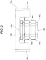
- a reactor 1 according to the present embodiment is provided with a core part 10 formed in combination of a substantially E-shaped partial core 10A (only one partial core is shown in FIG. 1 ) with a partial core 10B (see FIG. 3B ) facing this partial core 10A, and a coil part 20 wound around a circumference of central leg parts 13A, 13B.
- the central leg parts 13A, 13B each are formed into a trapezoidal shape in a cross section, and the coil part 20 wound around the circumference is also formed into the trapezoidal shape in which a rectangular wire is wound therearound by edgewise winding.
- the coil part 20 can cope with a relatively large current by using the rectangular wire.
- the coil part 20 is formed into the trapezoidal shape in which a lower base is longer than an upper base in the cross section, and a large outer peripheral surface that forms the lower base is abutted on a heat transfer sheet 30 over a wide area (herein, a side or a surface on a side of the heat transfer sheet 30 is referred to as the lower base).
- a side or a surface on a side of the heat transfer sheet 30 is referred to as the lower base.
- the rectangular wire is wound therearound by edgewise winding, and therefore, in each turn in the coil part 20, an inner periphery and an outer periphery are to be formed as one side edge and the other side edge of the same rectangular wire material, respectively, and heat can be quickly transferred from a coil part inner peripheral part easily heated at high temperature to the heat transfer sheet 30 abutted on a coil outer peripheral part.
- the heat transfer sheet 30 faces a heat sink (not shown) (water in the case of water cooling: the same shall apply hereinafter) through a bottom surface wall part of a case 50, and the heat transferred to the heat transfer sheet 30 is dissipated from the heat sink to outside.
- a heat sink not shown
- water in the case of water cooling the same shall apply hereinafter
- right and left leg parts 11A, 12A of the partial cores 10A, 10B (hereinafter, also referred to as the core part 10 in combination of the partial cores 10A, 10B) each are formed to be wide in an upper part and narrow toward a lower part so as to come along an outer shape of the trapezoidal shape of the coil part 20.
- the core part 10 in combination of the partial cores 10A, 10B each are formed to be wide in an upper part and narrow toward a lower part so as to come along an outer shape of the trapezoidal shape of the coil part 20.
- the central leg parts 13A, 13B are formed into a configuration in which a magnetic portion and a spacer portion (magnetic body or non-magnetic body) are alternately arranged.
- the magnetic portion is formed of a central projection part 15A of the partial core 10A, magnetic core pieces 15B, 15C in the trapezoidal shape in the cross section, and a central projection part 15D of the partial core 10B, and first spacers 16A, 16C and a second spacer 16B, each being the non-magnetic portion, are interposed into a place between the portions, respectively, for these four magnetic portions.
- a trapezoidal cross section of the spacers 16A to 16C each is formed to be one size smaller than a trapezoidal cross section of parts 15A to 15D each in the magnetic portions.
- the central leg parts 13A, 13B are configured of the magnetic portions divided into four, and three non-magnetic portions arranged between these magnetic portions, and one interval between the magnetic portions is shortened, and therefore a magnetic flux leak quantity as a total can be reduced.
- the number other than the above-described number can be obviously applied.
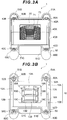
- FIG. 3A shows an overall external view of the reactor 1.
- the partial cores 10A, 10B are not illustrated in the external view because the cores are covered by other members, and therefore are illustrated in FIG. 3B in which bobbins 40A, 40B and the coil part 20 are removed.
- the respective partial cores 10A, 10B are covered by the bobbins 40A, 40B each that keep insulation of the cores from the coil part 20 or the like.
- the bobbins 40A, 40B are formed by being butted to each other in a state in which the bobbins 40A, 40B cover the respective partial cores 10A, 10B (a leading end of a leg part of the core is not covered) .
- respective angle portions are provided with jut-out parts 42A to 42D jutting out outward, respectively.
- An aluminum case 50 is formed so as to store the thus assembled bobbins 40A, 40B as a whole. Moreover, respective corner parts of the case 50 are provided with protrusion parts 51A to 51D protruding outward, and the jut-out parts 42A to 42D of the bobbins 40A, 40B are formed to be housed by the protrusion parts 51A to 51D.
- outer side surfaces of the above-described bobbins 40A, 40B are formed to be abutted on an inner wall surface of the case 50, and the bobbins 40A, 40B are just stored within the case 50.
- Through holes are perforated in the respective jut-out parts 42A to 42D of the bobbins 40A, 40B, and screws 60A to 60D are configured to be screwed, through the through holes, into upper surfaces of stepped parts (52A to 52D) rising from a bottom part of the case 50. More specifically, the bobbins 40A, 40B as a whole are pushed down toward the bottom part of the case 50 by screwing the screws 60A to 60D thereinto, lower end surfaces of the bobbins 40A, 40B, being portions covering the central leg parts 13A, 13B, press an inner peripheral surface of the coil part 20 downward, and a lower outer peripheral surface of the coil part 20 is to be pressed onto an upper surface of the heat transfer sheet 30.
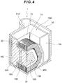
- FIG. 4 showing an internal state in which, while a lower end surface of a bobbin 40A covering a central leg part 13A is abutted on an inner peripheral part of a lower base portion of a coil part 20, an upper end surface of the bobbin 40A faces, with spacing, an inner peripheral part of an upper base portion of the coil part 20, and is not abutted on the coil part 20.
- the heat generated in the coil part 20 can be effectively dissipated to outside through the heat transfer sheet 30.
- the heat transfer sheet 30 faces the heat sink (not shown) through the bottom surface wall part of the case 50, and the heat transferred to the heat transfer sheet 30 is dissipated from the heat sink to outside.
- an assembly of the core part 10, the coil part 20, and the bobbins 40A, 40B can be integrally clamped to the case 50 with screws .
- the respective members are practically adhered to each other with an adhesive, when necessary, in a state of being positioned to each other.
- a relative position between the respective members is fixed by filling an insulating adhesive between the respective members.
- an insulating resin agent 71 of a silicon base, a urethane base, an epoxy base and the like is filled into a central hole 70 surrounded by the bobbins 40A, 40B.
- a resin has fluidity in an initial state, and therefore is infiltrated into a gap between the core part 10 and the coil part 20, and the insulation between both can be improved.
- the insulation can be ensured by using such an insulating resin agent 71, even if the gap between both described above is small. Therefore, a clearance can be made small, and compactification can be promoted.
- the reactor 1 is configured in such a manner that the central hole 70 surrounded by the bobbins 40A, 40B is configured in a state in which the bobbins 40A, 40B are assembled, and the insulating resin agent 71 having flowability is filled into the central hole 70 (filled into an uppermost part of the central hole 70), and over-molding including the coil part 20 as a whole can be made.
- the insulating resin agent 71 is penetrated into the gap between the core part 10 and the coil part 20, and the insulation between both can be ensured.
- an opening position of the central hole 70 of the bobbins 40A, 40B is set to be higher than an upper surface of the upper base of the coil part 20, and when the insulating resin agent 71 is filled into the central hole 70 surrounded by the bobbins 40A, 40B, the insulating resin agent 71 filled therein causes no overflow to outside, and the coil part 20 can be wholly covered with the insulating resin agent 71.
- the insulating resin agent 71 functions as a protective layer, and is capable of preventing occurrence of the respective members being damaged when the respective members are brought into contact with a member outside the reactor.
- the insulating resin agent 71 is designed to be filled only into the central hole 70 surrounded by the bobbins 40A, 40B, and in comparison with a case where the outer periphery of the bobbins 40A, 40B is wholly filled with the insulating resin agent 71, an amount of filling the insulating resin agent 71 can be significantly reduced.
- a unit price of the insulating resin agent 71 is high, and therefore according to the present embodiment, a production cost can be significantly reduced.
- the insulation and advantages of protection are not necessarily high, and therefore it is considered that no significant problem would occur even by filling the insulating resin agent 71 only into the central hole 70.
- the above-described core part 10 is formed of a powder magnetic core prepared by pulverizing a ferromagnetic material such as iron powders into fine powders, covering surfaces thereof with an insulating coat, and compressing and compacting the powders.
- a ferromagnetic material such as iron powders into fine powders, covering surfaces thereof with an insulating coat, and compressing and compacting the powders.
- Specific examples of the above-described ferromagnetic material include pure iron or an iron alloy containing at least one kind of additive element selected from elements of Ni, Cu, Cr, Mo, Mn, C, Si, Al, P, B, N and Co.
- the above-described coil part 20 is formed by winding the rectangular wire therearound.
- the rectangular wire is a band-shaped flat conducting wire, as shown in FIG. 1 or the like, in which a thickness of about 0.5 mm to about 6. 0mm and a width of about 1.0 mm to about 16.0mm are applied as a general shape, for example.
- the bobbins 40A, 40B have been formed into outer shapes to be one size larger than sizes of the partial cores 10A, 10B, respectively, in order to cover the core part 10, and taking into account moldability, mass productivity, fine processing, electric insulation, inexpensiveness, mechanical strength and the like, the bobbins 40A, 40B are molded by using an insulating resin such as a thermoplastic resin including PPS and 6,6-nylon, and a thermosetting resin including a phenolic resin and unsaturated polyester, for example.
- an insulating resin such as a thermoplastic resin including PPS and 6,6-nylon, and a thermosetting resin including a phenolic resin and unsaturated polyester, for example.
- the case 50 is formed of aluminum, but various other materials can be used therefor.
- the areas of the cross sections perpendicular to the direction in which the magnetic flux flows for example, an area of a leading end surface of the right and left leg part 11A and an area of a cross section of a root portion of the central leg part 13A (T-shaped portion combining a central protrusion part 15A and a core part body part 15E) are formed to be substantially equal to each other.
- Either a cross-sectional area of the right and left leg part 11A or a cross-sectional area of the central leg part 13A can be obviously set to be larger depending on circumstances.
- the cross-sectional area of the right and left leg part 11A can also be formed to be larger under a purpose of increasing an initial L value.
- the cross-sectional shape of the right and left leg part 11A is formed into a particular shape and the coil part 20 of the central leg parts 13A, 13B is formed into a trapezoidal shape, and therefore each is configured to be wide in an upper portion and narrow in a lower portion so as to come along the outer peripheral part of the coil part 20.
- the cross-sectional shape of the right and left leg part 11A is formed into a particular shape and the coil part 20 of the central leg parts 13A, 13B is formed into a trapezoidal shape, and therefore each is configured to be wide in an upper portion and narrow in a lower portion so as to come along the outer peripheral part of the coil part 20.
- the central leg parts 13A, 13B are configured into the trapezoidal shape in the cross section, and the shape of the coil part 20 wound therearound is formed to be the trapezoidal shape in the cross section.
- the reason why the coil part 20 is formed into the trapezoidal shape in the cross section is to increase a ratio of a length of the coil part 20 abutting on the heat transfer sheet 30 relative to a total length of the coil part20. More specifically, if the shape is formed into the trapezoidal shape in the cross section, the lower base becomes longer than the upper base. Therefore, if both side pieces have the same length, the ratio of the coil part 20 abutting on the heat transfer sheet 30 increases in comparison with the case of a rectangle in the cross section, and a heat dissipating effect can be improved as a theory.
- FIG. 5 shows an aspect in which an outer peripheral surface of a coil part 20A is abutted on a heat transfer sheet 30A in contact with a heat sink 80A when a core part 10D and a coil part 20A each have a trapezoidal shape (trapezoid-like shape).
- FIG. 5 shows an aspect in which, when the coil part 20A has the trapezoidal shape in the cross section, a ratio of contact of the heat transfer sheet 30A with the outer peripheral surface of the coil part 20A increases.
- the heat-dissipating effect can be improved. Accordingly, a triangle shaped material in which the upper base is made smallest to a limit can cause further improvement in the heat-dissipating effect.
- FIG. 6 shows a concept of a reactor according to a modified shape of the present invention, and shows an aspect in which, when a core part 10E and a coil part 20B each have a triangular shape in a cross section (triangle-like shape), an outer peripheral surface of the coil part 20B is abutted on a heat transfer sheet 30B in contact with a heat sink 80B.
- FIG. 6 shows an aspect in which, when the coil part 20B has the triangular shape in the cross section, a ratio of contact of the heat transfer sheet 30B with the outer peripheral surface of the coil part 20B further increases.
- the coil part 20B when the coil part 20B is formed into the triangular shape, an interior angle becomes acute at an apex of the triangle, and it becomes difficult to fold the rectangular wire in a longitudinal direction.
- the angle when the angle is significantly below 60 degrees, the rectangular wire is liable to be damaged during folding, and therefore, it is important to take into account that the interior angle is formed to be 60 degrees or more.
- FIG. 7 shows a concept of a reactor according to a conventional technology 1, and shows an aspect in which, when a core part 110D and a coil part 120A each have a circular shape in a cross section (circle-like shape), an outer peripheral surface of the coil part 120A is abutted on a heat transfer sheet 130A in contact with a heat sink 180A.
- FIG. 7 shows an aspect in which, when the coil part 120A has the circular shape, the outer peripheral surface of the coil part 120A and the heat transfer sheet 130A are substantially formed into a point contact (practically, line contact), heat-dissipating properties significantly decrease.
- FIG. 8 shows a concept of a reactor according to a conventional technology 2, and shows an aspect in which, when a core part 110E and a coil part 120B each have a square shape in a cross section (square-like shape), an outer peripheral surface of the coil part 120B is abutted on a heat transfer sheet 130B in contact with a heat sink 180B.
- FIG. 8 shows a concept of a reactor according to a conventional technology 2, and shows an aspect in which, when a core part 110E and a coil part 120B each have a square shape in a cross section (square-like shape), an outer peripheral surface of the coil part 120B is abutted on a heat transfer sheet 130B in contact with a heat sink 180B.
- FIG. 8 shows an aspect in which, when the coil part 120B has the square shape, a side positioned downward has a length equal to a length of a side positioned upward, and in comparison with the case where the coil part 20A is formed into the trapezoidal shape as in the embodiment described above or the coil part 20B is formed into the triangular shape as in the modified shape described above, a ratio of contact of the heat transfer sheet 130B with the outer peripheral surface of the coil part 120B decreases, and therefore heat-dissipating properties are reduced.
- the core part 10 is molded, and then the core part 10 and the coil part 20 are set inside an insert molding machine in a state in which both are stored inside the case 50 as shown in FIG. 3A , and further filling the insulating resin agent 71 into the central hole 70 of the bobbins 40A, 40B, and then integral molding processing is applied thereto in a mold.
- the reactor 1 as a whole can be integrated quickly and reliably while the insulation is maintained.
- a coil component according to the present invention is not limited to a material in the above-described embodiment and the above-described modified shape, and can be modified into various other aspects.
- the cross sectional shape of the core part or the coil part is not limited to the shape in the above-described embodiment and in the above-described modified shape, and can be modified into various shapes or types other than the above-described shapes or types.
- a pentagon-shaped core part or coil part can be used in place of the above-described core part or coil part having the trapezoidal shape in the cross section. In this case, it is necessary to take into account that the interior angle at the apex increases and a risk of the rectangular wire being damaged during folding the rectangular wire becomes small, but on the other hand, the number of steps required for folding the rectangular wire increases, and production efficiency is reduced.
- the coil part is formed in such a manner that the lower base has a length as large as one and a half times or more a length of the upper base, and a minimum of interior angle is 60 degrees or more.
- the coil part is formed in such a manner that a length of a side abutting on the heat transfer sheet is in a maximum length among all sides and a minimum of interior angles becomes 60 degrees or more.
- leading ends of the leg parts 11A, 11B, 12A, 12B, 13A, 13B corresponding to the respective E-shaped partial cores 10A, 10B are butted to each other and combined.
- leading end portions with each other may be chamfered so as to form a curved shape as a whole.
- Favorable DC superimposition characteristics can be achieved by forming each of the leading end portions into such a curved shape.
- Example a sample in Example was prepared by forming a core part 10F and a coil part 20D each having a trapezoidal shape in a cross section as shown in FIG. 9A , similar to an embodiment, and setting thermal conductivity (W/m ⁇ k) of each member as shown in Table 1. Simultaneously therewith, as Comparative Example, a sample in Comparative Example was prepared by forming a core part 110F and a coil part 120D each having a rectangular shape in a cross section as shown in FIG. 9B , and setting thermal conductivity (W/m ⁇ k) of each member as shown in Table 1.
- cross-sectional areas of central leg parts 13F, 113F and cross-sectional areas of right and left leg parts 11F, 12F and 111F, 112F were set to be equal to each other between Example and Comparative Example.
- a distance between the core part 10F and the coil part 20D and between the core part 110F and the coil part 120D was set to 2.3 mm for all the samples in Example and Comparative Example.
- Other members each were formed into the same size.
- an insulating resin agent 71 was filled only into a central hole 70 in the embodiment.
- An atmospheric temperature was set to 85°C (under no wind) in both Example and Comparative Example.
- a heat-dissipating effect was evaluated on the sample in Example and the sample in Comparative Example each prepared as described above by simulating a case upon passing, through the coil part 20D or 120D, a current having a waveform obtained by superimposing a high frequency ripple current on DC 100 A, under the above-described conditions, and deriving an average temperature (average temperature inside each component) and a maximum temperature (temperature on a site to be a maximum temperature within the component) at a time after elapse of 3,000 seconds from start of passing the current therethrough, and calculating the heat-dissipating effect from the temperatures derived therefrom.
- Example 2 As shown in Table 2, between Example and Comparative Example, the temperatures in the coil part 20D and the coil part 120D were different by 3.55°C in an average value. More specifically, in the sample in Example, the heat-dissipating effect superb as high as 3.55°C was obtained in the average value in comparison with the sample in Comparative Example. In comparison of temperature rise values, in the sample in Example, measurement results superb as high as 7.6% were obtained in comparison with the sample in Comparative Example.
- respective temperature ranges shown in FIG. 10A and FIG. 10B are represented in a state in which the temperature ranges are divided into 6 regions, sequentially from a side of a high temperature region: (1) 112 to 121.5°C, (2) 102.5 to 112°C, (3) 93 to 102.5°C, (4) 83.5 to 93°C, (5) 64.5 to 83.5°C and (6) 55 to 64.5°C.
- An art includes a core part 10 provided with central leg parts 13A, 13B and right and left leg parts 11A, 11B, 12A, 12B arranged on both sides of the central leg parts 13A, 13B; a coil part 20 formed by winding a conducting wire around a circumference of the central leg parts 13A, 13B; and a heat transfer sheet 30 for dissipating heat in the coil part 20 to outside, in which the coil part 20 is configured in such a manner that a rectangular wire is wound around the circumference of the central leg parts by edgewise winding and a circumference of the coil part 20 wound therearound is abutted on the heat transfer sheet 30.
Landscapes
- Engineering & Computer Science (AREA)
- Power Engineering (AREA)
- Manufacturing & Machinery (AREA)
- Microelectronics & Electronic Packaging (AREA)
- Coils Of Transformers For General Uses (AREA)
- Transformer Cooling (AREA)
- Manufacturing Cores, Coils, And Magnets (AREA)
Applications Claiming Priority (1)
| Application Number | Priority Date | Filing Date | Title |
|---|---|---|---|
| JP2017027320A JP2018133500A (ja) | 2017-02-16 | 2017-02-16 | リアクトルおよびその製造方法 |
Publications (3)
| Publication Number | Publication Date |
|---|---|
| EP3364431A2 true EP3364431A2 (de) | 2018-08-22 |
| EP3364431A3 EP3364431A3 (de) | 2018-10-31 |
| EP3364431B1 EP3364431B1 (de) | 2020-06-17 |
Family
ID=60781669
Family Applications (1)
| Application Number | Title | Priority Date | Filing Date |
|---|---|---|---|
| EP17207999.8A Active EP3364431B1 (de) | 2017-02-16 | 2017-12-18 | Reaktor |
Country Status (4)
| Country | Link |
|---|---|
| US (1) | US11183329B2 (de) |
| EP (1) | EP3364431B1 (de) |
| JP (1) | JP2018133500A (de) |
| CN (1) | CN108447648B (de) |
Families Citing this family (9)
| Publication number | Priority date | Publication date | Assignee | Title |
|---|---|---|---|---|
| US11404203B2 (en) * | 2018-06-13 | 2022-08-02 | General Electric Company | Magnetic unit and an associated method thereof |
| US11538615B2 (en) * | 2018-09-25 | 2022-12-27 | Toyota Jidosha Kabushiki Kaisha | Reactor and method of manufacturing the same |
| CN112740514B (zh) * | 2018-09-25 | 2024-09-13 | 松下知识产权经营株式会社 | 线圈的安装构造、定子和马达 |
| US20220108825A1 (en) * | 2019-03-19 | 2022-04-07 | Mitsubishi Electric Corporation | Coil Device and Power Conversion Device |
| JP6871293B2 (ja) * | 2019-03-22 | 2021-05-12 | 株式会社タムラ製作所 | リアクトル |
| JP7251377B2 (ja) * | 2019-07-19 | 2023-04-04 | スミダコーポレーション株式会社 | 磁気結合型リアクトル装置 |
| JP7085658B1 (ja) * | 2021-01-27 | 2022-06-16 | 本田技研工業株式会社 | 多相リアクトル |
| JP2022116899A (ja) * | 2021-01-29 | 2022-08-10 | Tdk株式会社 | コイル部品及びこれを備える携帯端末ホルダー |
| JP7691905B2 (ja) * | 2021-10-20 | 2025-06-12 | Tdk株式会社 | コイル装置 |
Citations (2)
| Publication number | Priority date | Publication date | Assignee | Title |
|---|---|---|---|---|
| JP2012124401A (ja) | 2010-12-10 | 2012-06-28 | Toyota Motor Corp | リアクトルとその製造方法 |
| JP2015188022A (ja) | 2014-03-27 | 2015-10-29 | 株式会社デンソー | リアクトル放熱構造 |
Family Cites Families (23)
| Publication number | Priority date | Publication date | Assignee | Title |
|---|---|---|---|---|
| US3007125A (en) * | 1958-02-20 | 1961-10-31 | Gen Electric | Inductive device |
| US3332049A (en) * | 1965-11-30 | 1967-07-18 | Tdk Electronics Co Ltd | Magnetic core unit with shielded winding |
| US4352081A (en) * | 1980-10-22 | 1982-09-28 | Kijima Musen Kabushiki Kaisha | Compact trans core |
| JPH0521232A (ja) * | 1991-07-15 | 1993-01-29 | Sony Corp | インダクタンス素子 |
| US5210513A (en) * | 1992-03-20 | 1993-05-11 | General Motors Corporation | Cooling of electromagnetic apparatus |
| WO2006033071A1 (en) * | 2004-09-24 | 2006-03-30 | Philips Intellectual Property & Standards Gmbh | Transformer |
| JP5212077B2 (ja) * | 2008-12-17 | 2013-06-19 | トヨタ自動車株式会社 | 電磁機器及びその冷却構造 |
| JPWO2011089941A1 (ja) * | 2010-01-20 | 2013-05-23 | 住友電気工業株式会社 | リアクトル |
| US8570133B2 (en) * | 2010-03-25 | 2013-10-29 | Panasonic Corporation | Transformer |
| JP5240246B2 (ja) * | 2010-06-23 | 2013-07-17 | トヨタ自動車株式会社 | リアクトル |
| JP2012039098A (ja) * | 2010-07-13 | 2012-02-23 | Sumitomo Electric Ind Ltd | リアクトル及びコイル部品 |
| JP5867677B2 (ja) * | 2010-07-13 | 2016-02-24 | 住友電気工業株式会社 | リアクトル、コンバータ及び電力変換装置 |
| JP2012023267A (ja) * | 2010-07-16 | 2012-02-02 | Toyota Motor Corp | リアクトル |
| JP5597106B2 (ja) * | 2010-11-19 | 2014-10-01 | 住友電気工業株式会社 | リアクトル |
| JPWO2013018381A1 (ja) | 2011-08-01 | 2015-03-05 | 住友電気工業株式会社 | チョークコイル |
| JP6283976B2 (ja) * | 2013-01-16 | 2018-02-28 | 日立金属株式会社 | コモンモードチョーク |
| JP6288513B2 (ja) * | 2013-12-26 | 2018-03-07 | 株式会社オートネットワーク技術研究所 | リアクトル |
| JP6288531B2 (ja) * | 2014-06-24 | 2018-03-07 | 株式会社オートネットワーク技術研究所 | コア部材、リアクトル、及びコア部材の製造方法 |
| JP2016092313A (ja) * | 2014-11-10 | 2016-05-23 | 三菱電機株式会社 | 磁気部品 |
| JP6160605B2 (ja) * | 2014-12-24 | 2017-07-12 | トヨタ自動車株式会社 | リアクトル |
| CN105869828B (zh) | 2015-01-22 | 2018-10-09 | 台达电子工业股份有限公司 | 磁性元件 |
| CN106803455B (zh) * | 2015-11-26 | 2019-07-26 | 乾坤科技股份有限公司 | 平面型电抗器 |
| US10366817B2 (en) * | 2017-05-02 | 2019-07-30 | General Electric Company | Apparatus and method for passive cooling of electronic devices |
-
2017
- 2017-02-16 JP JP2017027320A patent/JP2018133500A/ja active Pending
- 2017-11-10 CN CN201711102757.1A patent/CN108447648B/zh active Active
- 2017-11-28 US US15/824,425 patent/US11183329B2/en active Active
- 2017-12-18 EP EP17207999.8A patent/EP3364431B1/de active Active
Patent Citations (2)
| Publication number | Priority date | Publication date | Assignee | Title |
|---|---|---|---|---|
| JP2012124401A (ja) | 2010-12-10 | 2012-06-28 | Toyota Motor Corp | リアクトルとその製造方法 |
| JP2015188022A (ja) | 2014-03-27 | 2015-10-29 | 株式会社デンソー | リアクトル放熱構造 |
Also Published As
| Publication number | Publication date |
|---|---|
| EP3364431B1 (de) | 2020-06-17 |
| CN108447648B (zh) | 2021-07-20 |
| US11183329B2 (en) | 2021-11-23 |
| EP3364431A3 (de) | 2018-10-31 |
| JP2018133500A (ja) | 2018-08-23 |
| CN108447648A (zh) | 2018-08-24 |
| US20180233281A1 (en) | 2018-08-16 |
Similar Documents
| Publication | Publication Date | Title |
|---|---|---|
| EP3364431B1 (de) | Reaktor | |
| US8525632B2 (en) | Reactor | |
| US10283255B2 (en) | Reactor | |
| US10483029B2 (en) | Core member, reactor, and method for manufacturing core member | |
| EP2584574B1 (de) | Reaktor | |
| WO2011089941A1 (ja) | リアクトル | |
| JP6288510B2 (ja) | リアクトル | |
| JP7255153B2 (ja) | リアクトルおよびその製造方法 | |
| JPWO2016031993A1 (ja) | リアクトル | |
| JP7215036B2 (ja) | リアクトル | |
| JP5234517B2 (ja) | リアクトル、リアクトルの製造方法、及びコンバータ | |
| JP2018190910A (ja) | リアクトル装置およびその製造方法 | |
| JP6557527B2 (ja) | リアクトル | |
| US11942251B2 (en) | Reactor | |
| US20170040100A1 (en) | Core piece and reactor | |
| KR20160134633A (ko) | 권선형 인덕터 및 그 제조 방법 | |
| US20200118727A1 (en) | Reactor | |
| US12431270B2 (en) | Magnetic component and electric device | |
| CN110942902B (zh) | 电抗器及其制造方法 | |
| US11908613B2 (en) | Reactor | |
| JP7193975B2 (ja) | リアクトル | |
| JP7786239B2 (ja) | コイル部品 | |
| US11557423B2 (en) | Coil and reactor | |
| WO2024253007A1 (ja) | インダクタ及びインダクタの製造方法 | |
| KR20170127237A (ko) | 인덕터 및 이의 제조 방법 |
Legal Events
| Date | Code | Title | Description |
|---|---|---|---|
| PUAI | Public reference made under article 153(3) epc to a published international application that has entered the european phase |
Free format text: ORIGINAL CODE: 0009012 |
|
| STAA | Information on the status of an ep patent application or granted ep patent |
Free format text: STATUS: REQUEST FOR EXAMINATION WAS MADE |
|
| 17P | Request for examination filed |
Effective date: 20171218 |
|
| AK | Designated contracting states |
Kind code of ref document: A2 Designated state(s): AL AT BE BG CH CY CZ DE DK EE ES FI FR GB GR HR HU IE IS IT LI LT LU LV MC MK MT NL NO PL PT RO RS SE SI SK SM TR |
|
| AX | Request for extension of the european patent |
Extension state: BA ME |
|
| PUAL | Search report despatched |
Free format text: ORIGINAL CODE: 0009013 |
|
| AK | Designated contracting states |
Kind code of ref document: A3 Designated state(s): AL AT BE BG CH CY CZ DE DK EE ES FI FR GB GR HR HU IE IS IT LI LT LU LV MC MK MT NL NO PL PT RO RS SE SI SK SM TR |
|
| AX | Request for extension of the european patent |
Extension state: BA ME |
|
| RIC1 | Information provided on ipc code assigned before grant |
Ipc: H01F 37/00 20060101ALI20180922BHEP Ipc: H01F 27/28 20060101ALI20180922BHEP Ipc: H01F 27/22 20060101AFI20180922BHEP Ipc: H01F 17/04 20060101ALI20180922BHEP |
|
| STAA | Information on the status of an ep patent application or granted ep patent |
Free format text: STATUS: EXAMINATION IS IN PROGRESS |
|
| STAA | Information on the status of an ep patent application or granted ep patent |
Free format text: STATUS: REQUEST FOR EXAMINATION WAS MADE |
|
| STAA | Information on the status of an ep patent application or granted ep patent |
Free format text: STATUS: EXAMINATION IS IN PROGRESS |
|
| 17Q | First examination report despatched |
Effective date: 20190812 |
|
| REG | Reference to a national code |
Ref country code: DE Ref legal event code: R079 Ref document number: 602017018255 Country of ref document: DE Free format text: PREVIOUS MAIN CLASS: H01F0027220000 Ipc: H01F0027255000 |
|
| GRAP | Despatch of communication of intention to grant a patent |
Free format text: ORIGINAL CODE: EPIDOSNIGR1 |
|
| STAA | Information on the status of an ep patent application or granted ep patent |
Free format text: STATUS: GRANT OF PATENT IS INTENDED |
|
| RIC1 | Information provided on ipc code assigned before grant |
Ipc: H01F 27/255 20060101AFI20200304BHEP Ipc: H01F 27/32 20060101ALI20200304BHEP Ipc: H01F 37/00 20060101ALI20200304BHEP Ipc: H01F 27/28 20060101ALI20200304BHEP Ipc: H01F 41/12 20060101ALI20200304BHEP Ipc: H01F 27/22 20060101ALI20200304BHEP |
|
| INTG | Intention to grant announced |
Effective date: 20200327 |
|
| GRAS | Grant fee paid |
Free format text: ORIGINAL CODE: EPIDOSNIGR3 |
|
| GRAA | (expected) grant |
Free format text: ORIGINAL CODE: 0009210 |
|
| STAA | Information on the status of an ep patent application or granted ep patent |
Free format text: STATUS: THE PATENT HAS BEEN GRANTED |
|
| AK | Designated contracting states |
Kind code of ref document: B1 Designated state(s): AL AT BE BG CH CY CZ DE DK EE ES FI FR GB GR HR HU IE IS IT LI LT LU LV MC MK MT NL NO PL PT RO RS SE SI SK SM TR |
|
| REG | Reference to a national code |
Ref country code: GB Ref legal event code: FG4D |
|
| REG | Reference to a national code |
Ref country code: CH Ref legal event code: EP |
|
| REG | Reference to a national code |
Ref country code: IE Ref legal event code: FG4D |
|
| REG | Reference to a national code |
Ref country code: DE Ref legal event code: R096 Ref document number: 602017018255 Country of ref document: DE |
|
| REG | Reference to a national code |
Ref country code: AT Ref legal event code: REF Ref document number: 1282340 Country of ref document: AT Kind code of ref document: T Effective date: 20200715 |
|
| PG25 | Lapsed in a contracting state [announced via postgrant information from national office to epo] |
Ref country code: SE Free format text: LAPSE BECAUSE OF FAILURE TO SUBMIT A TRANSLATION OF THE DESCRIPTION OR TO PAY THE FEE WITHIN THE PRESCRIBED TIME-LIMIT Effective date: 20200617 Ref country code: FI Free format text: LAPSE BECAUSE OF FAILURE TO SUBMIT A TRANSLATION OF THE DESCRIPTION OR TO PAY THE FEE WITHIN THE PRESCRIBED TIME-LIMIT Effective date: 20200617 Ref country code: GR Free format text: LAPSE BECAUSE OF FAILURE TO SUBMIT A TRANSLATION OF THE DESCRIPTION OR TO PAY THE FEE WITHIN THE PRESCRIBED TIME-LIMIT Effective date: 20200918 Ref country code: NO Free format text: LAPSE BECAUSE OF FAILURE TO SUBMIT A TRANSLATION OF THE DESCRIPTION OR TO PAY THE FEE WITHIN THE PRESCRIBED TIME-LIMIT Effective date: 20200917 Ref country code: LT Free format text: LAPSE BECAUSE OF FAILURE TO SUBMIT A TRANSLATION OF THE DESCRIPTION OR TO PAY THE FEE WITHIN THE PRESCRIBED TIME-LIMIT Effective date: 20200617 |
|
| REG | Reference to a national code |
Ref country code: LT Ref legal event code: MG4D |
|
| REG | Reference to a national code |
Ref country code: NL Ref legal event code: MP Effective date: 20200617 |
|
| PG25 | Lapsed in a contracting state [announced via postgrant information from national office to epo] |
Ref country code: RS Free format text: LAPSE BECAUSE OF FAILURE TO SUBMIT A TRANSLATION OF THE DESCRIPTION OR TO PAY THE FEE WITHIN THE PRESCRIBED TIME-LIMIT Effective date: 20200617 Ref country code: BG Free format text: LAPSE BECAUSE OF FAILURE TO SUBMIT A TRANSLATION OF THE DESCRIPTION OR TO PAY THE FEE WITHIN THE PRESCRIBED TIME-LIMIT Effective date: 20200917 Ref country code: HR Free format text: LAPSE BECAUSE OF FAILURE TO SUBMIT A TRANSLATION OF THE DESCRIPTION OR TO PAY THE FEE WITHIN THE PRESCRIBED TIME-LIMIT Effective date: 20200617 Ref country code: LV Free format text: LAPSE BECAUSE OF FAILURE TO SUBMIT A TRANSLATION OF THE DESCRIPTION OR TO PAY THE FEE WITHIN THE PRESCRIBED TIME-LIMIT Effective date: 20200617 |
|
| REG | Reference to a national code |
Ref country code: AT Ref legal event code: MK05 Ref document number: 1282340 Country of ref document: AT Kind code of ref document: T Effective date: 20200617 |
|
| PG25 | Lapsed in a contracting state [announced via postgrant information from national office to epo] |
Ref country code: NL Free format text: LAPSE BECAUSE OF FAILURE TO SUBMIT A TRANSLATION OF THE DESCRIPTION OR TO PAY THE FEE WITHIN THE PRESCRIBED TIME-LIMIT Effective date: 20200617 Ref country code: AL Free format text: LAPSE BECAUSE OF FAILURE TO SUBMIT A TRANSLATION OF THE DESCRIPTION OR TO PAY THE FEE WITHIN THE PRESCRIBED TIME-LIMIT Effective date: 20200617 |
|
| PG25 | Lapsed in a contracting state [announced via postgrant information from national office to epo] |
Ref country code: AT Free format text: LAPSE BECAUSE OF FAILURE TO SUBMIT A TRANSLATION OF THE DESCRIPTION OR TO PAY THE FEE WITHIN THE PRESCRIBED TIME-LIMIT Effective date: 20200617 Ref country code: SM Free format text: LAPSE BECAUSE OF FAILURE TO SUBMIT A TRANSLATION OF THE DESCRIPTION OR TO PAY THE FEE WITHIN THE PRESCRIBED TIME-LIMIT Effective date: 20200617 Ref country code: EE Free format text: LAPSE BECAUSE OF FAILURE TO SUBMIT A TRANSLATION OF THE DESCRIPTION OR TO PAY THE FEE WITHIN THE PRESCRIBED TIME-LIMIT Effective date: 20200617 Ref country code: ES Free format text: LAPSE BECAUSE OF FAILURE TO SUBMIT A TRANSLATION OF THE DESCRIPTION OR TO PAY THE FEE WITHIN THE PRESCRIBED TIME-LIMIT Effective date: 20200617 Ref country code: PT Free format text: LAPSE BECAUSE OF FAILURE TO SUBMIT A TRANSLATION OF THE DESCRIPTION OR TO PAY THE FEE WITHIN THE PRESCRIBED TIME-LIMIT Effective date: 20201019 Ref country code: IT Free format text: LAPSE BECAUSE OF FAILURE TO SUBMIT A TRANSLATION OF THE DESCRIPTION OR TO PAY THE FEE WITHIN THE PRESCRIBED TIME-LIMIT Effective date: 20200617 Ref country code: RO Free format text: LAPSE BECAUSE OF FAILURE TO SUBMIT A TRANSLATION OF THE DESCRIPTION OR TO PAY THE FEE WITHIN THE PRESCRIBED TIME-LIMIT Effective date: 20200617 Ref country code: CZ Free format text: LAPSE BECAUSE OF FAILURE TO SUBMIT A TRANSLATION OF THE DESCRIPTION OR TO PAY THE FEE WITHIN THE PRESCRIBED TIME-LIMIT Effective date: 20200617 |
|
| PG25 | Lapsed in a contracting state [announced via postgrant information from national office to epo] |
Ref country code: IS Free format text: LAPSE BECAUSE OF FAILURE TO SUBMIT A TRANSLATION OF THE DESCRIPTION OR TO PAY THE FEE WITHIN THE PRESCRIBED TIME-LIMIT Effective date: 20201017 Ref country code: PL Free format text: LAPSE BECAUSE OF FAILURE TO SUBMIT A TRANSLATION OF THE DESCRIPTION OR TO PAY THE FEE WITHIN THE PRESCRIBED TIME-LIMIT Effective date: 20200617 Ref country code: SK Free format text: LAPSE BECAUSE OF FAILURE TO SUBMIT A TRANSLATION OF THE DESCRIPTION OR TO PAY THE FEE WITHIN THE PRESCRIBED TIME-LIMIT Effective date: 20200617 |
|
| REG | Reference to a national code |
Ref country code: DE Ref legal event code: R097 Ref document number: 602017018255 Country of ref document: DE |
|
| PLBE | No opposition filed within time limit |
Free format text: ORIGINAL CODE: 0009261 |
|
| STAA | Information on the status of an ep patent application or granted ep patent |
Free format text: STATUS: NO OPPOSITION FILED WITHIN TIME LIMIT |
|
| PG25 | Lapsed in a contracting state [announced via postgrant information from national office to epo] |
Ref country code: DK Free format text: LAPSE BECAUSE OF FAILURE TO SUBMIT A TRANSLATION OF THE DESCRIPTION OR TO PAY THE FEE WITHIN THE PRESCRIBED TIME-LIMIT Effective date: 20200617 |
|
| 26N | No opposition filed |
Effective date: 20210318 |
|
| PG25 | Lapsed in a contracting state [announced via postgrant information from national office to epo] |
Ref country code: SI Free format text: LAPSE BECAUSE OF FAILURE TO SUBMIT A TRANSLATION OF THE DESCRIPTION OR TO PAY THE FEE WITHIN THE PRESCRIBED TIME-LIMIT Effective date: 20200617 |
|
| REG | Reference to a national code |
Ref country code: CH Ref legal event code: PL |
|
| PG25 | Lapsed in a contracting state [announced via postgrant information from national office to epo] |
Ref country code: MC Free format text: LAPSE BECAUSE OF FAILURE TO SUBMIT A TRANSLATION OF THE DESCRIPTION OR TO PAY THE FEE WITHIN THE PRESCRIBED TIME-LIMIT Effective date: 20200617 |
|
| REG | Reference to a national code |
Ref country code: BE Ref legal event code: MM Effective date: 20201231 |
|
| PG25 | Lapsed in a contracting state [announced via postgrant information from national office to epo] |
Ref country code: LU Free format text: LAPSE BECAUSE OF NON-PAYMENT OF DUE FEES Effective date: 20201218 Ref country code: IE Free format text: LAPSE BECAUSE OF NON-PAYMENT OF DUE FEES Effective date: 20201218 |
|
| PG25 | Lapsed in a contracting state [announced via postgrant information from national office to epo] |
Ref country code: LI Free format text: LAPSE BECAUSE OF NON-PAYMENT OF DUE FEES Effective date: 20201231 Ref country code: CH Free format text: LAPSE BECAUSE OF NON-PAYMENT OF DUE FEES Effective date: 20201231 |
|
| PG25 | Lapsed in a contracting state [announced via postgrant information from national office to epo] |
Ref country code: TR Free format text: LAPSE BECAUSE OF FAILURE TO SUBMIT A TRANSLATION OF THE DESCRIPTION OR TO PAY THE FEE WITHIN THE PRESCRIBED TIME-LIMIT Effective date: 20200617 Ref country code: MT Free format text: LAPSE BECAUSE OF FAILURE TO SUBMIT A TRANSLATION OF THE DESCRIPTION OR TO PAY THE FEE WITHIN THE PRESCRIBED TIME-LIMIT Effective date: 20200617 Ref country code: CY Free format text: LAPSE BECAUSE OF FAILURE TO SUBMIT A TRANSLATION OF THE DESCRIPTION OR TO PAY THE FEE WITHIN THE PRESCRIBED TIME-LIMIT Effective date: 20200617 |
|
| PG25 | Lapsed in a contracting state [announced via postgrant information from national office to epo] |
Ref country code: MK Free format text: LAPSE BECAUSE OF FAILURE TO SUBMIT A TRANSLATION OF THE DESCRIPTION OR TO PAY THE FEE WITHIN THE PRESCRIBED TIME-LIMIT Effective date: 20200617 |
|
| PG25 | Lapsed in a contracting state [announced via postgrant information from national office to epo] |
Ref country code: BE Free format text: LAPSE BECAUSE OF NON-PAYMENT OF DUE FEES Effective date: 20201231 |
|
| PGFP | Annual fee paid to national office [announced via postgrant information from national office to epo] |
Ref country code: DE Payment date: 20251211 Year of fee payment: 9 |
|
| PGFP | Annual fee paid to national office [announced via postgrant information from national office to epo] |
Ref country code: GB Payment date: 20251219 Year of fee payment: 9 |
|
| PGFP | Annual fee paid to national office [announced via postgrant information from national office to epo] |
Ref country code: FR Payment date: 20251229 Year of fee payment: 9 |