EP3357793B1 - Parking assist apparatus - Google Patents
Parking assist apparatus Download PDFInfo
- Publication number
- EP3357793B1 EP3357793B1 EP17190788.4A EP17190788A EP3357793B1 EP 3357793 B1 EP3357793 B1 EP 3357793B1 EP 17190788 A EP17190788 A EP 17190788A EP 3357793 B1 EP3357793 B1 EP 3357793B1
- Authority
- EP
- European Patent Office
- Prior art keywords
- image
- parking
- vehicle
- target frame
- display
- Prior art date
- Legal status (The legal status is an assumption and is not a legal conclusion. Google has not performed a legal analysis and makes no representation as to the accuracy of the status listed.)
- Active
Links
- 230000002093 peripheral effect Effects 0.000 claims description 29
- 238000003384 imaging method Methods 0.000 description 39
- 238000010586 diagram Methods 0.000 description 10
- 230000006870 function Effects 0.000 description 4
- 230000000694 effects Effects 0.000 description 2
- 235000004522 Pentaglottis sempervirens Nutrition 0.000 description 1
- 230000015572 biosynthetic process Effects 0.000 description 1
- 238000006243 chemical reaction Methods 0.000 description 1
- 239000000470 constituent Substances 0.000 description 1
- 230000001419 dependent effect Effects 0.000 description 1
- 238000005401 electroluminescence Methods 0.000 description 1
- 230000007613 environmental effect Effects 0.000 description 1
- 239000004973 liquid crystal related substance Substances 0.000 description 1
- 238000000034 method Methods 0.000 description 1
- 238000012986 modification Methods 0.000 description 1
- 230000004048 modification Effects 0.000 description 1
- 230000003287 optical effect Effects 0.000 description 1
- 239000007787 solid Substances 0.000 description 1
- 238000003786 synthesis reaction Methods 0.000 description 1
Images


Classifications
-
- B—PERFORMING OPERATIONS; TRANSPORTING
- B62—LAND VEHICLES FOR TRAVELLING OTHERWISE THAN ON RAILS
- B62D—MOTOR VEHICLES; TRAILERS
- B62D15/00—Steering not otherwise provided for
- B62D15/02—Steering position indicators ; Steering position determination; Steering aids
- B62D15/027—Parking aids, e.g. instruction means
- B62D15/028—Guided parking by providing commands to the driver, e.g. acoustically or optically
-
- B—PERFORMING OPERATIONS; TRANSPORTING
- B60—VEHICLES IN GENERAL
- B60W—CONJOINT CONTROL OF VEHICLE SUB-UNITS OF DIFFERENT TYPE OR DIFFERENT FUNCTION; CONTROL SYSTEMS SPECIALLY ADAPTED FOR HYBRID VEHICLES; ROAD VEHICLE DRIVE CONTROL SYSTEMS FOR PURPOSES NOT RELATED TO THE CONTROL OF A PARTICULAR SUB-UNIT
- B60W30/00—Purposes of road vehicle drive control systems not related to the control of a particular sub-unit, e.g. of systems using conjoint control of vehicle sub-units
- B60W30/06—Automatic manoeuvring for parking
-
- B—PERFORMING OPERATIONS; TRANSPORTING
- B62—LAND VEHICLES FOR TRAVELLING OTHERWISE THAN ON RAILS
- B62D—MOTOR VEHICLES; TRAILERS
- B62D15/00—Steering not otherwise provided for
- B62D15/02—Steering position indicators ; Steering position determination; Steering aids
- B62D15/027—Parking aids, e.g. instruction means
- B62D15/0285—Parking performed automatically
-
- G—PHYSICS
- G01—MEASURING; TESTING
- G01S—RADIO DIRECTION-FINDING; RADIO NAVIGATION; DETERMINING DISTANCE OR VELOCITY BY USE OF RADIO WAVES; LOCATING OR PRESENCE-DETECTING BY USE OF THE REFLECTION OR RERADIATION OF RADIO WAVES; ANALOGOUS ARRANGEMENTS USING OTHER WAVES
- G01S7/00—Details of systems according to groups G01S13/00, G01S15/00, G01S17/00
- G01S7/52—Details of systems according to groups G01S13/00, G01S15/00, G01S17/00 of systems according to group G01S15/00
- G01S7/56—Display arrangements
-
- G—PHYSICS
- G06—COMPUTING; CALCULATING OR COUNTING
- G06V—IMAGE OR VIDEO RECOGNITION OR UNDERSTANDING
- G06V20/00—Scenes; Scene-specific elements
- G06V20/50—Context or environment of the image
- G06V20/56—Context or environment of the image exterior to a vehicle by using sensors mounted on the vehicle
- G06V20/58—Recognition of moving objects or obstacles, e.g. vehicles or pedestrians; Recognition of traffic objects, e.g. traffic signs, traffic lights or roads
-
- G—PHYSICS
- G08—SIGNALLING
- G08G—TRAFFIC CONTROL SYSTEMS
- G08G1/00—Traffic control systems for road vehicles
- G08G1/16—Anti-collision systems
- G08G1/168—Driving aids for parking, e.g. acoustic or visual feedback on parking space
-
- B—PERFORMING OPERATIONS; TRANSPORTING
- B60—VEHICLES IN GENERAL
- B60T—VEHICLE BRAKE CONTROL SYSTEMS OR PARTS THEREOF; BRAKE CONTROL SYSTEMS OR PARTS THEREOF, IN GENERAL; ARRANGEMENT OF BRAKING ELEMENTS ON VEHICLES IN GENERAL; PORTABLE DEVICES FOR PREVENTING UNWANTED MOVEMENT OF VEHICLES; VEHICLE MODIFICATIONS TO FACILITATE COOLING OF BRAKES
- B60T2201/00—Particular use of vehicle brake systems; Special systems using also the brakes; Special software modules within the brake system controller
- B60T2201/10—Automatic or semi-automatic parking aid systems
-
- G—PHYSICS
- G01—MEASURING; TESTING
- G01S—RADIO DIRECTION-FINDING; RADIO NAVIGATION; DETERMINING DISTANCE OR VELOCITY BY USE OF RADIO WAVES; LOCATING OR PRESENCE-DETECTING BY USE OF THE REFLECTION OR RERADIATION OF RADIO WAVES; ANALOGOUS ARRANGEMENTS USING OTHER WAVES
- G01S13/00—Systems using the reflection or reradiation of radio waves, e.g. radar systems; Analogous systems using reflection or reradiation of waves whose nature or wavelength is irrelevant or unspecified
- G01S13/88—Radar or analogous systems specially adapted for specific applications
- G01S13/93—Radar or analogous systems specially adapted for specific applications for anti-collision purposes
- G01S13/931—Radar or analogous systems specially adapted for specific applications for anti-collision purposes of land vehicles
- G01S2013/9314—Parking operations
Definitions
- This invention relates to a parking assist apparatus.
- a parking assist apparatus that assists parking or exit by a driver by being mounted on a vehicle such as an automobile and displaying a host vehicle image and an overhead image of a periphery of the vehicle on a display device.
- Examples of related art include JP 2009-49943 A and JP 2016-66322 A .
- document EP 2 583 869 A1 discloses a parking assistance apparatus comprising a region detector for detecting possible parking regions, image acquisition part for acquiring the scene surrounding the vehicle, a display controller for displaying the photographic image on a monitor device and superimposing graphic images showing parking target candidates in positions where the possible parking regions detected by the region detector correspond on the photographic image, and a selection part for selecting one of the parking target candidates as a parking target on the basis of command input from a driving device of the vehicle.
- a parking mode selection apparatus and method are disclosed, that cause display of an environmental image around a vehicle to a driver in order to invite the driver to select a parking mode of the vehicle.
- the object of the invention is achieved by a parking assist apparatus according to the features of claim 1.
- a parking assist apparatus includes: a peripheral image generation portion that generates an overhead image of a periphery viewed from a view point above a vehicle based on a captured image of a periphery of a vehicle; and a display image generation portion that generates a display image by superimposing a host vehicle image displaying the vehicle on one of left and right sides in the overhead image and superimposing a target frame displaying a target of a movement destination of the vehicle on the other of the left and right sides in the overhead image in an assist mode of a forward parking or a backward exit.
- the display image includes first buttons for selecting a parking direction in the assist mode of the forward parking and second buttons for selecting an exit direction in the assist mode of the backward exit, wherein, in the assist mode of the forward parking, the target frame is superimposed on the other of the left and right sides corresponding to the selected first buttons, and in the assist mode of the backward exit, the target frame is superimposed on the other of the left and right side corresponding to the selected second buttons.
- an appropriate display image including the host vehicle image and the target frame can be displayed.
- the display image generation portion may superimpose the host vehicle image on a rear side in the overhead image in the assist mode of the forward parking and may superimpose the host vehicle image on a front side in the overhead image in the assist mode of the backward exit.
- the overhead image of a region on the traveling direction side of the vehicle can be further displayed on the display image by the overhead image of a region on a side opposite to a traveling direction of the vehicle being omitted.
- the display image generation portion may superimpose the target frame on a left side in the overhead image and the host vehicle image on a right side in the overhead image in a case of the assist mode for assisting the forward parking or the backward exit with respect to the target frame on a left side of the vehicle and may superimpose the target frame on a right side in the overhead image and the host vehicle image on a left side in the overhead image in a case of the assist mode for assisting the forward parking or the backward exit with respect to the target frame on a right side of the vehicle.
- the host vehicle image and the target frame can be more reliably displayed even in the display image by an overhead image having a narrow field of view range.
- the display image generation portion may superimpose the target frame on a preset set path in which the host vehicle image is set as a starting point.
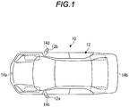
- Fig. 1 is a plan view of a vehicle 10 according to the embodiment. As illustrated in Fig. 1 , the vehicle 10 includes a vehicle body 12 and four imaging portions 14a, 14b, 14c, and 14d. In a case where it is not necessary to distinguish the imaging portions 14a, 14b, 14c, and 14d, they are described as the imaging portion 14.
- the vehicle body 12 constitutes an occupant compartment where occupants ride.
- the vehicle body 12 accommodates and holds the imaging portion 14 and the like.
- the imaging portion 14 is, for example, a digital camera incorporating an imaging device such as a charge coupled device (CCD) or CMOS image sensor (CIS).
- the imaging portion 14 can output a moving image including a plurality of frame images generated at a predetermined frame rate or data of a still image as data of a captured image.
- Each of the imaging portions 14 has a wide angle lens or a fisheye lens, and can image a range of 140° to 190° in the horizontal direction.
- the optical axis of the imaging portion 14 is set obliquely downward. Therefore, the imaging portion 14 outputs captured image data imaged the periphery including the road surface of a periphery of the vehicle 10.
- the imaging portion 14 is provided on a periphery of the vehicle body 12.
- the imaging portion 14a is provided at a center portion (for example, front bumper) of the front end portion of the vehicle body 12 in the lateral direction.
- the imaging portion 14a generates a captured image obtained by imaging a periphery of the front side of the vehicle 10.
- the imaging portion 14b is provided at a center portion (for example, rear bumper) of the rear end portion of the vehicle body 12 in the lateral direction.
- the imaging portion 14b generates a captured image obtained by imaging a periphery of the rear side of the vehicle 10.
- the imaging portion 14c is provided at a center portion (for example, left side mirror 12a) of the left end portion of the vehicle body 12 in the front and rear direction.
- the imaging portion 14c generates a captured image obtained by imaging a periphery of the left side of the vehicle 10.
- the imaging portion 14d is provided at a center portion (for example, right side mirror 12b) of the right end portion of the vehicle body 12 in the front and rear direction.
- the imaging portion 14d generates a captured image obtained by imaging a periphery of the right side of the vehicle 10.
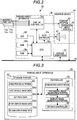
- Fig. 2 is a block diagram illustrating the configuration of a parking assist system 30 mounted on the vehicle 10. As illustrated in Fig. 2 , the parking assist system 30 further includes an automatic driving portion 32, a monitor device 34, a parking assist apparatus 36, and an in-vehicle network 38.
- the automatic driving portion 32 controls an accelerator, a brake, a steering wheel, and the like based on an instruction from the parking assist apparatus 36 to automatically drive the vehicle 10 during the parking and during the exit, or the like.
- the monitor device 34 is provided in a dashboard or the like in the occupant compartment.
- the monitor device 34 includes a display portion 40, a voice output portion 42, and an operation input portion 44.
- the display portion 40 displays an image based on the image data transmitted by the parking assist apparatus 36.
- the display portion 40 is, for example, a display device such as a liquid crystal display (LCD) or an organic electro luminescence display (OELD).
- LCD liquid crystal display
- OELD organic electro luminescence display
- the voice output portion 42 outputs voice based on the voice data transmitted by the parking assist apparatus 36.
- the voice output portion 42 is, for example, a speaker.
- the voice output portion 42 may be provided at a different position from the display portion 40 in the occupant compartment.
- the operation input portion 44 receives an input by an occupant.
- the operation input portion 44 is, for example, a touch panel.
- the operation input portion 44 is provided on a display screen of the display portion 40.
- the operation input portion 44 is configured to be capable of transmitting the image displayed by the display portion 40. Accordingly, the operation input portion 44 can visually recognize the image displayed on the display screen of the display portion 40 by the occupant.
- the operation input portion 44 receives an instruction input by touching the position corresponding to the image displayed on the display screen of the display portion 40 by the occupant and thus transmits the instruction to the parking assist apparatus 36.
- the parking assist apparatus 36 is a computer including a microcomputer such as an electronic control unit (ECU).
- the parking assist apparatus 36 acquires data of the captured image from the imaging portion 14.
- the parking assist apparatus 36 transmits data relating to an image or voice generated based on the captured image or the like to the monitor device 34.
- the parking assist apparatus 36 controls the automatic driving portion 32 to assist the vehicle 10 by automatically driving the vehicle 10 during the parking or during the exit.
- the parking assist apparatus 36 includes a central processing unit (CPU) 36a, a read only memory (ROM) 36b, a random access memory (RAM) 36c, a display controller 36d, a voice controller 36e, a solid state drive (SSD) 36f.
- the CPU 36a, the ROM 36b and the RAM 36c may be integrated in the same package.
- the CPU 36a is an example of a hardware processor, reads a program stored in a nonvolatile storage device such as the ROM 36b, and executes various calculation processing and control according to the program. For example, the CPU 36a executes image processing such as an image for parking assist to be displayed on the display portion 40.
- the ROM 36b stores each program and parameters necessary for executing the program and the like.
- the RAM 36c temporarily stores various data used in the calculation in the CPU 36a.
- the display controller 36d mainly executes processing of the image obtained by the imaging portion 14, the data conversion of the display image to be displayed on the display portion 40 among the calculation processing by the parking assist apparatus 36.
- the voice controller 36e mainly executes processing of the voice to be output to the voice output portion 42 among the calculation processing by the parking assist apparatus 36.
- the SSD 36f is a rewritable nonvolatile storage portion and maintains data even in a case where the power source of the parking assist apparatus 36 is turned off.
- the parking assist apparatus 36 cooperates with hardware and software (control program) to manage assist processing during parking and exit of the vehicle 10.
- the parking assist apparatus 36 generates display images 68 and 70 in which the host vehicle image and the target frame are superimposed on the top view type peripheral image generated based on the captured image including the peripheral image captured by the imaging portion 14 and thus displays the display images on the display portion 40.
- the parking assist apparatus 36 controls the automatic driving portion 32 to move the vehicle 10 to the target frame by automatic driving to assist the parking and the exit.
- the in-vehicle network 38 is, for example, a controller area network (CAN).
- the in-vehicle network 38 electrically connects the automatic driving portion 32, the parking assist apparatus 36, and the operation input portion 44 so that signals and information can be transmitted and received with each other.
- CAN controller area network
- Fig. 3 is a functional block diagram explaining the function of the parking assist apparatus 36. As illustrated in Fig. 3 , the parking assist apparatus 36 includes a controller 50 and a storage portion 52.
- the controller 50 is realized, for example, using a function of the CPU 36a.
- the controller 50 includes a mode determination portion 54, a peripheral image generation portion 56, a display image generation portion 58, and a driving controller 60.
- the controller 50 may realize the functions of the mode determination portion 54, the peripheral image generation portion 56, the display image generation portion 58, and the driving controller 60.
- a portion or all of the mode determination portion 54, the peripheral image generation portion 56, the display image generation portion 58, and the driving controller 60 may be configured by hardware such as a circuit including an application specific integrated circuit (ASIC).
- ASIC application specific integrated circuit
- the mode determination portion 54 receives from the operation input portion 44 instructions of mode switching to an assist mode that assists the parking or the exit by automatic driving by an occupant. Furthermore, after the mode switching from the navigation mode to the assist mode, the mode determination portion 54 determines the parking assist mode or the exit assist mode selected by the occupant based on the input from the operation input portion 44.
- the assist mode includes a forward parking mode and a backward parking mode.
- the forward parking mode includes a left forward parking mode for parking to the left front target frame, a right forward parking mode for parking to the right front target frame, a right backward exit mode for exiting to the right rear target frame, and left backward exit mode for exiting to the left rear target frame.
- the backward parking mode includes a left backward parking mode for parking to the left rear target frame, a right backward parking mode for parking to the right rear target frame, a right forward exit mode for exiting to the right front target frame, and a left forward exit mode for exiting to the left front target frame.
- the peripheral image generation portion 56 In the assist mode of forward parking or backward exit, the peripheral image generation portion 56 generates an overhead image of the periphery viewed from above, based on the captured image of the periphery of the vehicle 10 acquired from the imaging portion 14.
- the overhead image is also referred to as a top view image or a bird's eye image.
- the peripheral image generation portion 56 generates the overhead image by executing image processing and synthesis processing on a plurality of captured images obtained from the plurality of imaging portions 14. Specifically, the peripheral image generation portion 56 generates an overhead image centered on the parking direction side or the exit direction side as viewed from the vehicle 10, that is, the overhead image centered on a direction side where the target frame is set as viewed from the vehicle 10.
- the peripheral image generation portion 56 In a case of the left forward parking mode, since the target frame is set to the left front, the peripheral image generation portion 56 generates an overhead image centered on the left front of the vehicle 10.
- the peripheral image generation portion 56 generates an overhead image of the vehicle 10 in all directions based on the captured image and then trims a necessary region on the traveling direction side of the vehicle 10, and thus an overhead image 72 centered on the traveling direction side of the vehicle 10 may be generated.
- the peripheral image generation portion 56 in the backward parking or forward exit assist mode, the peripheral image generation portion 56 generates an overhead image centered on the position of the vehicle 10 based on the captured image.
- the peripheral image generation portion 56 outputs the generated overhead image together with the captured image to the display image generation portion 58.
- the position in the overhead image will be described based on the front, rear, left and right directions of the vehicle 10.
- the display image generation portion 58 In the assist mode of the forward parking or the backward exit, the display image generation portion 58 generate a first display image by superimposing the host vehicle image on one of left and right sides of the overhead image and by superimposing the target frame displaying the target of the movement destination of the vehicle 10 on the other of the left and right sides in the overhead image.
- the display image generation portion 58 in the forward parking assist mode, the display image generation portion 58 superimposes the host vehicle image on the rear side in the overhead image.
- the display image generation portion 58 in the backward exit assist mode, the display image generation portion 58 superimposes the host vehicle image on the front side in the overhead image.
- the display image generation portion 58 in a case of forward parking and backward exit, the display image generation portion 58 superimposes the host vehicle image on a side opposite to the traveling direction in the overhead image as viewed from the center of the overhead image.
- the display image generation portion 58 superimposes the target frame on the left side in the overhead image.
- the display image generation portion 58 superimposes the target frame on the right side in the overhead image. In other words, the display image generation portion 58 superimposes the target frame on a portion on a side opposite to the host vehicle image in the overhead image.
- the display image generation portion 58 superimposes the host vehicle image on the right rear side of the overhead image.
- the display image generation portion 58 superimposes the target frame on a preset set path in which the host vehicle image is set in the overhead image as a starting point based on set path data 66d in the storage portion 52.
- the display image generation portion 58 superimposes the target frame on the left front position in the overhead image.
- the display image generation portion 58 In the assist mode of the backward parking and the forward exit, the display image generation portion 58 generates a first display image by superimposing the host vehicle image on the center in the overhead image and superimposing the target frame on the set path in which the host vehicle image is set in the overhead image as a starting point.
- the display image generation portion 58 generates a second display image in which the target frame is superimposed on the captured image. Specifically, the display image generation portion 58 superimposes the target frame on the captured image so that it is at the same position as the real world position of the target frame in the first display image in the real world and thus the second display image is generated.
- the display image generation portion 58 stores the first display image data 68d and the second display image data 70d which are the data of the generated first display image and the generated second display image in the storage portion 52 and displays the first display image and the second display image on the display portion 40.
- the driving controller 60 determines the start of the automatic driving based on the position of the target frame and the like and starts the automatic driving, the driving controller 60 controls the automatic driving portion 32 to automatically drive the vehicle 10 and moves the vehicle 10 to the target frame along the preset set path.
- the storage portion 52 stores programs to be executed by the controller 50, data necessary for execution of the programs, data generated by execution of the programs, and the like.
- the storage portion 52 stores an assist processing program 62 executed by the controller 50.
- the storage portion 52 stores the host vehicle image data 64d necessary for executing the assist processing program 62 and the set path data 66d from the host vehicle position to the target frame.
- the set path data 66d may include data of a plurality of set paths associated with any one of the vehicle speed at the time of starting the assist, the steering angle of the steering wheel, and the like.
- the storage portion 52 temporarily stores the first display image data 68d and the second display image data 70d generated by execution of the assist processing program 62.
- Fig. 4 is a diagram illustrating an example of the display images 68 and 70 in the left forward parking mode in the parking assist of automatic driving.
- the display image generation portion 58 In the left forward parking mode, the display image generation portion 58 generates the first display image 68 including the overhead image 72 illustrated in Fig. 4 and the second display image 70 including a captured image 75 and thus displays the first display image 68 and the second display image 70 on the display portion 40.
- the peripheral image generation portion 56 generates an overhead image 72 which is a peripheral image centered on the left front which is the parking direction of the vehicle 10 from the captured images of the periphery acquired by the imaging portions 14a, 14b, and 14c and outputs the overhead image 72 to the display image generation portion 58.
- the display image generation portion 58 superimposes a portion of the host vehicle image 64 (for example, front half portion of host vehicle image 64) on the right rear end portion of the overhead image 72 which is a side opposite to the parking direction.
- the display image generation portion 58 superimposes a target frame 76a on the set path (for example, end point of set path) in which the host vehicle image 64 of the overhead image 72 is set as a starting point in the parking direction side in the overhead image 72. Accordingly, the display image generation portion 58 generates the first display image 68.
- An example of the shape of the target frame 76a in the real world is 5.1 m in length in the front and rear direction of the vehicle 10 after parking, 30 ° in inclination with respect to the front and rear direction of the vehicle 10, and 2.9 m in length in a direction inclined with respect to the front and rear direction of the vehicle 10.
- the shape of the target frame 76a may be appropriately changed according to the size of the vehicle 10 and the shape of the parking frame line 82 or the like indicated by a white line or the like in a parking lot.
- the display image generation portion 58 superimposes the target frame 76b on the captured image 75 captured by the imaging portion 14b and thus generates the second display image 70.
- the display image generation portion 58 superimposes the target frame 76b on the captured image 75 and thus generates the second display image 70 so that the positions of the target frame 76a of the first display image 68 and the target frame 76b of the second display image 70 in the real world are at the same position.
- the display image generation portion 58 may display a mode switching button on the second display image 70.
- the display image generation portion 58 may display a forward parking button 78a for selecting the forward parking mode and a backward parking button 78b for selecting the backward parking mode as the mode switching buttons.
- the display image generation portion 58 may display a left forward parking button 80a for selecting the left forward parking mode, a right forward parking button 80b for selecting the right forward parking mode, a right backward exit button 80c for selecting the right backward parking mode, and a left backward exit button 80d for selecting the left backward parking mode.
- a left forward parking button 80a for selecting the left forward parking mode
- a right forward parking button 80b for selecting the right forward parking mode
- a right backward exit button 80c for selecting the right backward parking mode
- a left backward exit button 80d for selecting the left backward parking mode.
- the occupant selects the left forward parking mode by operating the forward parking button 78a and the left forward parking button 80a as indicated by the thick frame.
- the buttons 78a and 78b and the buttons 80a to 80d it is described as a button 78 or a button 80.
- Fig. 5 is a diagram illustrating an example of the display images 68 and 70 in the left backward exit mode in the parking assist for automatic driving.
- the display image generation portion 58 In the left backward exit mode, the display image generation portion 58 generates the first display image 68 including the overhead image 72 illustrated in Fig. 5 and the second display image 70 including the captured image 75 and thus displays the first display image 68 and the second display image 70 on the display portion 40.
- the peripheral image generation portion 56 generates an overhead image 72 which is a peripheral image centered on the left rear which is the exit direction of the vehicle 10, from captured images of the periphery acquired from the imaging portions 14b, 14c, and 14d and thus outputs the overhead image 72 to the display image generation portion 58.
- the display image generation portion 58 superimposes a portion of the host vehicle image 64 (for example, rear half portion of host vehicle image 64) on the right front end portion of the overhead image 72.
- the display image generation portion 58 superimposes the target frame 76a on the set path (for example, end point of set path) in which the host vehicle image 64 of the overhead image 72 is set as a starting point. Accordingly, the display image generation portion 58 generates the first display image 68.
- An example of the shape of the target frame 76a in the real world is 5.1 m in length in the front and rear direction of the vehicle 10 after the parking and 2.5 m in length in the lateral direction of the vehicle 10.
- the shape of the target frame 76a may be appropriately changed according to the size of the vehicle 10 and the shape of the parking frame line 82 or the like indicated by a white line or the like in the parking lot.
- the display image generation portion 58 may display the exit start frame 84 on the overhead image 72.
- the exit start frame 84 is in a position to move the parked vehicle 10 by straight traveling so as to avoid contact with an adjacent vehicle or the like. Therefore, the driving controller 60 starts turning of the vehicle 10 after exceeding the exit start frame 84.
- the display image generation portion 58 may recognize the parking frame line 82 of the parking lot from the captured image and display the exit start frame 84 on the parking frame line 82 or may display the exit start frame 84 based on the preset exit start frame 84.
- the shape of the exit start frame 84 in the real world may be configured by a side having a length of 1 m parallel to the front and rear direction of the vehicle 10 during the parking and a side having a length of 1 m inclined by 30 ° from the lateral direction of the vehicle 10.
- the shape of the exit start frame 84 may be appropriately changed according to the size of the vehicle 10 and the shape of the parking frame line 82 or the like indicated by a white line or the like in the parking lot.
- the display image generation portion 58 superimposes the target frame 76b on the captured image 75 captured by the imaging portion 14b and generates the second display image 70.
- the display image generation portion 58 superimposes the target frame 76b on the captured image 75 so that the positions of the target frame 76a of the first display image 68 and the target frame 76b of the second display image 70 in the real world are at the same position and thus generates the second display image 70.
- the display image generation portion 58 may display buttons 78 and 80 for switching same mode as in Fig. 4 on the second display image 70.
- the occupant selects the left backward exit mode by operating the forward parking button 78a and the left backward exit button 80d as indicated by the thick frame.
- Fig. 6 is a diagram illustrating an example of the display images 68 and 70 in the left backward parking mode in the parking assist for automatic driving.
- the display image generation portion 58 In the left backward parking mode, the display image generation portion 58 generates the first display image 68 including the overhead image 72 illustrated in Fig. 6 and the second display image 70 including the captured image 75 and displays the first display image 68 and the second display image 70 on the display portion 40.
- the peripheral image generation portion 56 generates the overhead image 72 which is a peripheral image centered on the vehicle 10 from the captured images of the periphery acquired from the imaging portions 14a, 14b, 14c, and 14d and outputs the overhead image 72 to the display image generation portion 58.
- the display image generation portion 58 superimposes the host vehicle image 64 on the center of the overhead image 72.
- the display image generation portion 58 superimposes the target frame 76a on the set path (for example, end point of set path) in which the host vehicle image 64 of the overhead image 72 is set as a starting point. Accordingly, the display image generation portion 58 generates the first display image 68.
- the display image generation portion 58 can contain the target frame 76a in the first display image 68, even in the overhead image 72 centered on the vehicle 10.
- the display image generation portion 58 superimposes the target frame 76b on the captured image 75 captured by the imaging portion 14b, and generates the second display image 70.
- the display image generation portion 58 superimposes the target frame 76b on the captured image 75 so that the positions of the target frame 76a of the first display image 68 and the target frame 76b of the second display image 70 in the real world are at the same position and thus generates the second display image 70.
- the display image generation portion 58 may display the mode switching button in the second display image 70 in the backward parking mode.
- the display image generation portion 58 may display the forward parking button 78a for selecting the forward parking mode and the backward parking button 78b for selecting the backward parking mode as the mode switching button.
- the display image generation portion 58 may display a left backward parking button 80e for selecting the left backward parking mode, a right backward parking button 80f for selecting the right backward parking mode, a right forward exit button 80g for selecting a right forward exit mode, and the left forward exit button 80h for selecting the left forward exit mode.
- the occupant selects the left backward parking mode by operating the backward parking button 78b and the left backward parking button 80e as indicated by the thick frame.
- Fig. 7 is a flowchart illustrating assist processing executed by the controller 50.
- the controller 50 starts the assist processing by reading the assist processing program 62.
- the controller 50 receives and executes the selection of the parking assist mode or the exit assist mode by the occupant.
- the mode determination portion 54 of the controller 50 determines whether or not selection of the assist mode by automatic driving is received (S102).
- the mode determination portion 54 is in a standby state until selection of the assist mode is received (S102: No).
- the mode determination portion 54 determines that the assist mode is selected (S102: Yes), and outputs the display instructions of the buttons 78 and 80 to the display image generation portion 58.
- the display image generation portion 58 When acquiring the display instruction of the buttons 78 and 80, the display image generation portion 58 displays the parking button 78 and the exit button 80 (S104).
- the display image generation portion 58 may display the display images 68 and 70 illustrated in Fig. 4 to Fig. 6 together with the buttons 78, 80 on the display portion 40.
- the mode determination portion 54 determines whether or not the occupant has selected any one of the parking assist mode or the exit assist mode by the buttons 78 and 80 (S106). The mode determination portion 54 is in a standby state until being determined that the parking assist mode or the exit assist mode is selected (S106: No).
- the mode determination portion 54 determines that the occupant has selected any one of the parking assist mode or the exit assist mode (S106: Yes), and then outputs the information of the parking assist mode or the exit assist mode which is selected to the peripheral image generation portion 56.
- the peripheral image generation portion 56, the display image generation portion 58, and the driving controller 60 execute the parking assist processing or the exit assist processing according to the parking assist mode or the exit assist mode selected by the occupant (S108).
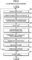
- Fig. 8 is a flowchart of the left forward parking assist processing which is a portion of the parking assist processing executed by the controller 50.
- the controller 50 executes the left forward parking assist processing which is one of the parking assist processing (S108).
- the peripheral image generation portion 56 of the parking assist apparatus 36 acquires a captured image from the imaging portion 14 (S202). Based on the captured image, the peripheral image generation portion 56 generates an overhead image 72 centered on the left front which is the traveling direction side of the vehicle 10 and then outputs the overhead image 72 and the captured image to the display image generation portion 58 (S204).
- the display image generation portion 58 superimposes a portion of the host vehicle image 64 on the end portion of the right rear side of the overhead image 72 (S206).
- the display image generation portion 58 sets a set path in which the position of the vehicle 10 is set as a starting point, based on the set path data 66d in the storage portion 52 (S208).
- the display image generation portion 58 superimposes the target frame 76a on the set path of the overhead image 72 to generate the first display image 68 as illustrated in Fig. 4 (S210).
- the display image generation portion 58 superimposes the target frame 76b on the position on the captured image 75 corresponding to the position of the target frame 76a of the first display image 68, installs the buttons 78 and 80 above the captured image 75, and generates a second display image 70 as illustrated in Fig. 4 (S212).
- the display image generation portion 58 displays the display images 68 and 70 on the display portion 40 (S214).
- the driving controller 60 determines whether or not automatic driving is started (S216). For example, the driving controller 60 may determine start of automatic driving when the target frames 76a and 76b overlap with the parking frame line 82 indicated by a white line or the like of the parking lot or the vehicle 10 stops. In addition, when the occupant touches the positions of the target frames 76a and 76b on the operation input portion 44 in a state where the target frames 76a and 76b overlap the parking frame line 82 of the white line of the parking lot, the driving controller 60 may determine start of the automatic driving.
- the driving controller 60 determines that automatic driving is not started (S216: No)
- the driving controller 60 repeats step S202 and the following steps. Accordingly, the peripheral image generation portion 56 and the display image generation portion 58 repeat generation of the display images 68 and 70 according to the movement of the vehicle 10 until the start of automatic driving and updates and displays the display images 68 and 70.
- the driving controller 60 determines the start of the automatic driving (S216: Yes)
- the driving controller 60 controls the automatic driving portion 32 to automatically drive the vehicle 10 and to move the vehicle 10 to the target frames 76a and 76b for parking (S218). Accordingly, the parking assist apparatus 36 ends the left forward parking assist processing which is one of the parking assist processing and ends the assist processing.
- the left forward parking assist processing and processing with respect to positions of left and right sides are different and the description with respect to the same processing except for the portion described above is omitted.
- Fig. 9 is a flowchart of the left backward exit assist processing executed by the controller 50.
- the controller 50 executes the left backward exit assist processing, which is one of the exit assist processing (S108).
- the peripheral image generation portion 56 of the parking assist apparatus 36 acquires a captured image from the imaging portion 14 (S302). Based on the captured image, the peripheral image generation portion 56 generates an overhead image 72 centered on the left rear side which is the traveling direction side of the vehicle 10 and then outputs the overhead image 72 and the captured image to the display image generation portion 58 (S304).
- the display image generation portion 58 superimposes a portion of the host vehicle image 64 on the end portion of the right front side of the overhead image 72 (S306).
- the display image generation portion 58 sets a set path in which the position of the vehicle 10 is set as a starting point (S308).
- the display image generation portion 58 superimposes the exit start frame 84 on the overhead image 72 (S310) and superimposes the target frame 76a on the set path of the overhead image 72 to generate the first display image 68 (S312).
- the display image generation portion 58 superimposes the target frame 76b on the position on the captured image 75 corresponding to the position of the target frame 76a of the first display image 68 and installs the buttons 78 and 80 above the captured image 75, and generates the second display image 70 (S314).
- the display image generation portion 58 displays the display images 68 and 70 on the display portion 40 (S316).
- the driving controller 60 determines whether or not to start automatic driving (S318). For example, when the occupant touches the positions of the target frames 76a and 76b on the operation input portion 44, the driving controller 60 may determine to start the automatic driving.
- step S302 If the driving controller 60 determines that automatic driving is not started (S318: No), step S302 and the following steps are repeated. Accordingly, the peripheral image generation portion 56 and the display image generation portion 58 repeat the generation of the display images 68 and 70 until the automatic driving is started.
- the driving controller 60 determines start of the automatic driving (S318: Yes)
- the driving controller 60 controls the automatic driving portion 32 to automatically drive the vehicle 10 and move the vehicle 10 to the target frames 76a and 76b and causes the vehicle 10 to execute backward exit (S320).
- the parking assist apparatus 36 ends the left backward exit assist processing which is one of the exit assist processing and ends the assist processing.
- the left backward exit assist processing and the processing with respect to positions of left and right sides are different and thus description with respect to the same portion except for the portion described above is omitted.
- the display image generation portion 58 superimposes the host vehicle image 64 on one of the left and right sides of the overhead image 72, and superimposes the target frame 76a on the other of the left and right sides to generate the first display image 68 in the assist mode of the forward parking and the backward exit. Accordingly, the parking assist apparatus 36 can more reliably contain the host vehicle image 64 and the target frame 76a in the first display image 68 as compared with a case where the host vehicle image 64 is displayed at the center of the overhead image 72.
- the parking assist apparatus 36 can display the appropriate first display image 68 including the host vehicle image 64 and the target frame 76a on the display portion 40. Further, the parking assist apparatus 36 reduces the processing load of the controller 50 configured by the processor such as the CPU 36a by narrowing the field of view range of the overhead image 72, and thus the above effect can be realized by the microcomputer including the inexpensive CPU 36a and the like and the imaging portion 14 having a narrow angle of view.
- the display image generation portion 58 superimposes the host vehicle image 64 on the rear side in the overhead image 72 in the forward parking mode in the parking assist apparatus 36 and superimposes the host vehicle image 64 on the front side in the overhead image 72 in the backward exit mode. Accordingly, in the assist mode, the parking assist apparatus 36 omits the overhead image 72 of the region on a side opposite to the traveling direction of the vehicle 10 and thus the host vehicle image 64 and the target frame 76a can be more reliably displayed in the first display image 68 by the overhead image 72 with emphasis on the region on the traveling direction side of the vehicle 10.
- the display image generation portion 58 superimposes the target frame 76a on the left side in the overhead image 72 in the forward parking mode and the backward exit mode to the target frame 76a of the left side of the vehicle 10 and superimposes the target frame 76a on the right side in the overhead image 72 in the forward parking mode and the backward exit mode to the target frame 76a of right side of the vehicle 10. Accordingly, the parking assist apparatus 36 can more reliably display the host vehicle image 64 and the target frame 76a, even with the first display image 68 including the overhead image 72 having a narrow field of view range.
- the display image generation portion 58 since the display image generation portion 58 superimposes the target frame 76a on the preset set path based on the set path data 66d, processing load required for calculation of the set path for setting the position where the target frame 76a is superimposed can be reduced.
- the parking assist system 30 may have three or less or five or more imaging portions 14.
Landscapes
- Engineering & Computer Science (AREA)
- Transportation (AREA)
- Mechanical Engineering (AREA)
- Chemical & Material Sciences (AREA)
- Combustion & Propulsion (AREA)
- Physics & Mathematics (AREA)
- General Physics & Mathematics (AREA)
- Computer Networks & Wireless Communication (AREA)
- Automation & Control Theory (AREA)
- Radar, Positioning & Navigation (AREA)
- Remote Sensing (AREA)
- Multimedia (AREA)
- Theoretical Computer Science (AREA)
- Closed-Circuit Television Systems (AREA)
- Traffic Control Systems (AREA)
- Image Processing (AREA)
- Image Analysis (AREA)
Applications Claiming Priority (1)
| Application Number | Priority Date | Filing Date | Title |
|---|---|---|---|
| JP2017017208A JP6946652B2 (ja) | 2017-02-02 | 2017-02-02 | 駐車支援装置 |
Publications (2)
| Publication Number | Publication Date |
|---|---|
| EP3357793A1 EP3357793A1 (en) | 2018-08-08 |
| EP3357793B1 true EP3357793B1 (en) | 2020-07-22 |
Family
ID=59858624
Family Applications (1)
| Application Number | Title | Priority Date | Filing Date |
|---|---|---|---|
| EP17190788.4A Active EP3357793B1 (en) | 2017-02-02 | 2017-09-13 | Parking assist apparatus |
Country Status (3)
| Country | Link |
|---|---|
| US (1) | US10308283B2 (ja) |
| EP (1) | EP3357793B1 (ja) |
| JP (1) | JP6946652B2 (ja) |
Families Citing this family (19)
| Publication number | Priority date | Publication date | Assignee | Title |
|---|---|---|---|---|
| US11505179B2 (en) * | 2018-10-03 | 2022-11-22 | Mitsubishi Electric Corporation | Parking assistance device and parking assistance method |
| JP7236857B2 (ja) | 2018-12-14 | 2023-03-10 | 株式会社デンソーテン | 画像処理装置および画像処理方法 |
| JP2020095631A (ja) | 2018-12-14 | 2020-06-18 | 株式会社デンソーテン | 画像処理装置および画像処理方法 |
| JP2020095623A (ja) | 2018-12-14 | 2020-06-18 | 株式会社デンソーテン | 画像処理装置および画像処理方法 |
| JP2020095620A (ja) | 2018-12-14 | 2020-06-18 | 株式会社デンソーテン | 画像処理装置および画像処理方法 |
| JP7203587B2 (ja) | 2018-12-14 | 2023-01-13 | 株式会社デンソーテン | 画像処理装置および画像処理方法 |
| JP7359541B2 (ja) | 2018-12-14 | 2023-10-11 | 株式会社デンソーテン | 画像処理装置および画像処理方法 |
| JP2020095624A (ja) | 2018-12-14 | 2020-06-18 | 株式会社デンソーテン | 画像処理装置、および画像処理方法 |
| JP7203586B2 (ja) * | 2018-12-14 | 2023-01-13 | 株式会社デンソーテン | 画像処理装置および画像処理方法 |
| JP7226986B2 (ja) | 2018-12-14 | 2023-02-21 | 株式会社デンソーテン | 画像処理装置および画像処理方法 |
| JP7141940B2 (ja) | 2018-12-14 | 2022-09-26 | 株式会社デンソーテン | 画像処理装置および画像処理方法 |
| JP7252750B2 (ja) | 2018-12-14 | 2023-04-05 | 株式会社デンソーテン | 画像処理装置および画像処理方法 |
| JP7195131B2 (ja) | 2018-12-14 | 2022-12-23 | 株式会社デンソーテン | 画像処理装置および画像処理方法 |
| JP2020147248A (ja) * | 2019-03-15 | 2020-09-17 | トヨタ自動車株式会社 | 車両制御システム |
| CN109741610A (zh) * | 2019-03-25 | 2019-05-10 | 西安艾润物联网技术服务有限责任公司 | 车辆进出识别方法、装置、设备及可读存储介质 |
| JP6998359B2 (ja) * | 2019-12-13 | 2022-01-18 | 本田技研工業株式会社 | 駐車支援システム |
| JP6998361B2 (ja) | 2019-12-13 | 2022-01-18 | 本田技研工業株式会社 | 駐車支援システム |
| MX2023004918A (es) * | 2020-11-02 | 2023-11-10 | Nissan Motor | Método de asistencia al estacionamiento y dispositivo de asistencia al estacionamiento. |
| US11514795B1 (en) * | 2021-05-18 | 2022-11-29 | Ford Global Technologies, Llc | Systems and methods of projecting virtual parking lines |
Citations (1)
| Publication number | Priority date | Publication date | Assignee | Title |
|---|---|---|---|---|
| EP2581273A1 (en) * | 2010-06-09 | 2013-04-17 | Nissan Motor Co., Ltd | Parking mode selection apparatus and method |
Family Cites Families (17)
| Publication number | Priority date | Publication date | Assignee | Title |
|---|---|---|---|---|
| JP3349836B2 (ja) * | 1994-09-22 | 2002-11-25 | アルパイン株式会社 | 車載用ナビゲーション装置 |
| JP2006248383A (ja) * | 2005-03-10 | 2006-09-21 | Nippon Soken Inc | 駐車支援装置 |
| JP5086562B2 (ja) * | 2006-04-17 | 2012-11-28 | クラリオン株式会社 | ナビゲーション装置 |
| JP2009049943A (ja) | 2007-08-22 | 2009-03-05 | Alpine Electronics Inc | 距離画像によるトップビュー表示装置 |
| US8407661B2 (en) * | 2008-07-28 | 2013-03-26 | Abb Research Ltd. | Method and system for creating HMI applications for an automation process |
| US8340870B2 (en) * | 2008-09-16 | 2012-12-25 | Honda Motor Co., Ltd. | Vehicle maneuver assistance device |
| TWI347900B (en) * | 2009-03-10 | 2011-09-01 | Univ Nat Chiao Tung | Parking assistance system and method |
| JP5155222B2 (ja) * | 2009-03-13 | 2013-03-06 | 本田技研工業株式会社 | 車両の出庫モード選択表示装置 |
| JP5035321B2 (ja) * | 2009-11-02 | 2012-09-26 | 株式会社デンソー | 車両周辺表示制御装置および車両周辺表示制御装置用のプログラム |
| JP2011205513A (ja) * | 2010-03-26 | 2011-10-13 | Aisin Seiki Co Ltd | 車両周辺監視装置 |
| WO2011158609A1 (ja) * | 2010-06-15 | 2011-12-22 | アイシン精機株式会社 | 運転支援装置 |
| JP5440867B2 (ja) * | 2010-06-18 | 2014-03-12 | アイシン精機株式会社 | 駐車支援装置 |
| JP5212748B2 (ja) * | 2010-09-29 | 2013-06-19 | アイシン精機株式会社 | 駐車支援装置 |
| JP6094266B2 (ja) * | 2013-02-28 | 2017-03-15 | アイシン精機株式会社 | 駐車支援装置、駐車支援方法およびプログラム |
| KR101426468B1 (ko) * | 2013-05-07 | 2014-08-05 | 현대모비스 주식회사 | Avm 상에서의 차량의 주차 안내 방법 |
| JP6100221B2 (ja) * | 2014-09-12 | 2017-03-22 | アイシン精機株式会社 | 出庫支援装置および出庫支援方法 |
| JP2016066322A (ja) | 2014-09-26 | 2016-04-28 | 富士通テン株式会社 | 画像処理装置、及び画像表示システム |
-
2017
- 2017-02-02 JP JP2017017208A patent/JP6946652B2/ja active Active
- 2017-09-13 EP EP17190788.4A patent/EP3357793B1/en active Active
- 2017-09-14 US US15/704,077 patent/US10308283B2/en active Active
Patent Citations (1)
| Publication number | Priority date | Publication date | Assignee | Title |
|---|---|---|---|---|
| EP2581273A1 (en) * | 2010-06-09 | 2013-04-17 | Nissan Motor Co., Ltd | Parking mode selection apparatus and method |
Also Published As
| Publication number | Publication date |
|---|---|
| JP2018122757A (ja) | 2018-08-09 |
| US20180215413A1 (en) | 2018-08-02 |
| US10308283B2 (en) | 2019-06-04 |
| JP6946652B2 (ja) | 2021-10-06 |
| EP3357793A1 (en) | 2018-08-08 |
Similar Documents
| Publication | Publication Date | Title |
|---|---|---|
| EP3357793B1 (en) | Parking assist apparatus | |
| EP3650285B1 (en) | Parking assistance method and parking assistance device | |
| JP5321267B2 (ja) | 車両用画像表示装置及び俯瞰画像の表示方法 | |
| US10179608B2 (en) | Parking assist device | |
| CN108886602B (zh) | 信息处理装置 | |
| JP2016084089A (ja) | 周辺監視装置 | |
| JP2018144526A (ja) | 周辺監視装置 | |
| EP3556611B1 (en) | On-vehicle display control device, on-vehicle display system, on-vehicle display control method, and non-transitory storage medium | |
| WO2018150642A1 (ja) | 周辺監視装置 | |
| US11017245B2 (en) | Parking assist apparatus | |
| JP7180144B2 (ja) | 運転支援装置 | |
| CN111186376A (zh) | 车辆电子镜系统 | |
| US20220144169A1 (en) | Rear-view camera system for a trailer hitch system | |
| US20210331680A1 (en) | Vehicle driving assistance apparatus | |
| JP2009171129A (ja) | 車両用駐車支援装置および画像表示方法 | |
| US20200140011A1 (en) | Parking assistance apparatus | |
| US20230290154A1 (en) | Control device, control method, and computer-readable recording medium | |
| JP2018165912A (ja) | 支援装置 | |
| US20200010076A1 (en) | Driving Support Device | |
| JP2012166689A (ja) | 運転支援装置 | |
| JP2006035995A (ja) | 車両用表示装置 | |
| US11091096B2 (en) | Periphery monitoring device | |
| US10922977B2 (en) | Display control device | |
| US20200148222A1 (en) | Driving support device | |
| JP2019135620A (ja) | 走行支援装置 |
Legal Events
| Date | Code | Title | Description |
|---|---|---|---|
| PUAI | Public reference made under article 153(3) epc to a published international application that has entered the european phase |
Free format text: ORIGINAL CODE: 0009012 |
|
| STAA | Information on the status of an ep patent application or granted ep patent |
Free format text: STATUS: REQUEST FOR EXAMINATION WAS MADE |
|
| 17P | Request for examination filed |
Effective date: 20180312 |
|
| AK | Designated contracting states |
Kind code of ref document: A1 Designated state(s): AL AT BE BG CH CY CZ DE DK EE ES FI FR GB GR HR HU IE IS IT LI LT LU LV MC MK MT NL NO PL PT RO RS SE SI SK SM TR |
|
| AX | Request for extension of the european patent |
Extension state: BA ME |
|
| STAA | Information on the status of an ep patent application or granted ep patent |
Free format text: STATUS: EXAMINATION IS IN PROGRESS |
|
| 17Q | First examination report despatched |
Effective date: 20190402 |
|
| GRAP | Despatch of communication of intention to grant a patent |
Free format text: ORIGINAL CODE: EPIDOSNIGR1 |
|
| STAA | Information on the status of an ep patent application or granted ep patent |
Free format text: STATUS: GRANT OF PATENT IS INTENDED |
|
| INTG | Intention to grant announced |
Effective date: 20200225 |
|
| GRAS | Grant fee paid |
Free format text: ORIGINAL CODE: EPIDOSNIGR3 |
|
| GRAA | (expected) grant |
Free format text: ORIGINAL CODE: 0009210 |
|
| STAA | Information on the status of an ep patent application or granted ep patent |
Free format text: STATUS: THE PATENT HAS BEEN GRANTED |
|
| AK | Designated contracting states |
Kind code of ref document: B1 Designated state(s): AL AT BE BG CH CY CZ DE DK EE ES FI FR GB GR HR HU IE IS IT LI LT LU LV MC MK MT NL NO PL PT RO RS SE SI SK SM TR |
|
| REG | Reference to a national code |
Ref country code: GB Ref legal event code: FG4D |
|
| REG | Reference to a national code |
Ref country code: CH Ref legal event code: EP |
|
| REG | Reference to a national code |
Ref country code: DE Ref legal event code: R096 Ref document number: 602017020081 Country of ref document: DE |
|
| REG | Reference to a national code |
Ref country code: AT Ref legal event code: REF Ref document number: 1293120 Country of ref document: AT Kind code of ref document: T Effective date: 20200815 |
|
| REG | Reference to a national code |
Ref country code: IE Ref legal event code: FG4D |
|
| REG | Reference to a national code |
Ref country code: LT Ref legal event code: MG4D |
|
| REG | Reference to a national code |
Ref country code: AT Ref legal event code: MK05 Ref document number: 1293120 Country of ref document: AT Kind code of ref document: T Effective date: 20200722 |
|
| PG25 | Lapsed in a contracting state [announced via postgrant information from national office to epo] |
Ref country code: FI Free format text: LAPSE BECAUSE OF FAILURE TO SUBMIT A TRANSLATION OF THE DESCRIPTION OR TO PAY THE FEE WITHIN THE PRESCRIBED TIME-LIMIT Effective date: 20200722 Ref country code: LT Free format text: LAPSE BECAUSE OF FAILURE TO SUBMIT A TRANSLATION OF THE DESCRIPTION OR TO PAY THE FEE WITHIN THE PRESCRIBED TIME-LIMIT Effective date: 20200722 Ref country code: PT Free format text: LAPSE BECAUSE OF FAILURE TO SUBMIT A TRANSLATION OF THE DESCRIPTION OR TO PAY THE FEE WITHIN THE PRESCRIBED TIME-LIMIT Effective date: 20201123 Ref country code: AT Free format text: LAPSE BECAUSE OF FAILURE TO SUBMIT A TRANSLATION OF THE DESCRIPTION OR TO PAY THE FEE WITHIN THE PRESCRIBED TIME-LIMIT Effective date: 20200722 Ref country code: GR Free format text: LAPSE BECAUSE OF FAILURE TO SUBMIT A TRANSLATION OF THE DESCRIPTION OR TO PAY THE FEE WITHIN THE PRESCRIBED TIME-LIMIT Effective date: 20201023 Ref country code: NO Free format text: LAPSE BECAUSE OF FAILURE TO SUBMIT A TRANSLATION OF THE DESCRIPTION OR TO PAY THE FEE WITHIN THE PRESCRIBED TIME-LIMIT Effective date: 20201022 Ref country code: ES Free format text: LAPSE BECAUSE OF FAILURE TO SUBMIT A TRANSLATION OF THE DESCRIPTION OR TO PAY THE FEE WITHIN THE PRESCRIBED TIME-LIMIT Effective date: 20200722 Ref country code: BG Free format text: LAPSE BECAUSE OF FAILURE TO SUBMIT A TRANSLATION OF THE DESCRIPTION OR TO PAY THE FEE WITHIN THE PRESCRIBED TIME-LIMIT Effective date: 20201022 Ref country code: SE Free format text: LAPSE BECAUSE OF FAILURE TO SUBMIT A TRANSLATION OF THE DESCRIPTION OR TO PAY THE FEE WITHIN THE PRESCRIBED TIME-LIMIT Effective date: 20200722 Ref country code: HR Free format text: LAPSE BECAUSE OF FAILURE TO SUBMIT A TRANSLATION OF THE DESCRIPTION OR TO PAY THE FEE WITHIN THE PRESCRIBED TIME-LIMIT Effective date: 20200722 |
|
| PG25 | Lapsed in a contracting state [announced via postgrant information from national office to epo] |
Ref country code: PL Free format text: LAPSE BECAUSE OF FAILURE TO SUBMIT A TRANSLATION OF THE DESCRIPTION OR TO PAY THE FEE WITHIN THE PRESCRIBED TIME-LIMIT Effective date: 20200722 Ref country code: RS Free format text: LAPSE BECAUSE OF FAILURE TO SUBMIT A TRANSLATION OF THE DESCRIPTION OR TO PAY THE FEE WITHIN THE PRESCRIBED TIME-LIMIT Effective date: 20200722 Ref country code: LV Free format text: LAPSE BECAUSE OF FAILURE TO SUBMIT A TRANSLATION OF THE DESCRIPTION OR TO PAY THE FEE WITHIN THE PRESCRIBED TIME-LIMIT Effective date: 20200722 Ref country code: IS Free format text: LAPSE BECAUSE OF FAILURE TO SUBMIT A TRANSLATION OF THE DESCRIPTION OR TO PAY THE FEE WITHIN THE PRESCRIBED TIME-LIMIT Effective date: 20201122 |
|
| PG25 | Lapsed in a contracting state [announced via postgrant information from national office to epo] |
Ref country code: NL Free format text: LAPSE BECAUSE OF FAILURE TO SUBMIT A TRANSLATION OF THE DESCRIPTION OR TO PAY THE FEE WITHIN THE PRESCRIBED TIME-LIMIT Effective date: 20200722 |
|
| REG | Reference to a national code |
Ref country code: DE Ref legal event code: R097 Ref document number: 602017020081 Country of ref document: DE |
|
| PG25 | Lapsed in a contracting state [announced via postgrant information from national office to epo] |
Ref country code: IT Free format text: LAPSE BECAUSE OF FAILURE TO SUBMIT A TRANSLATION OF THE DESCRIPTION OR TO PAY THE FEE WITHIN THE PRESCRIBED TIME-LIMIT Effective date: 20200722 Ref country code: EE Free format text: LAPSE BECAUSE OF FAILURE TO SUBMIT A TRANSLATION OF THE DESCRIPTION OR TO PAY THE FEE WITHIN THE PRESCRIBED TIME-LIMIT Effective date: 20200722 Ref country code: SM Free format text: LAPSE BECAUSE OF FAILURE TO SUBMIT A TRANSLATION OF THE DESCRIPTION OR TO PAY THE FEE WITHIN THE PRESCRIBED TIME-LIMIT Effective date: 20200722 Ref country code: DK Free format text: LAPSE BECAUSE OF FAILURE TO SUBMIT A TRANSLATION OF THE DESCRIPTION OR TO PAY THE FEE WITHIN THE PRESCRIBED TIME-LIMIT Effective date: 20200722 Ref country code: CZ Free format text: LAPSE BECAUSE OF FAILURE TO SUBMIT A TRANSLATION OF THE DESCRIPTION OR TO PAY THE FEE WITHIN THE PRESCRIBED TIME-LIMIT Effective date: 20200722 Ref country code: RO Free format text: LAPSE BECAUSE OF FAILURE TO SUBMIT A TRANSLATION OF THE DESCRIPTION OR TO PAY THE FEE WITHIN THE PRESCRIBED TIME-LIMIT Effective date: 20200722 |
|
| REG | Reference to a national code |
Ref country code: CH Ref legal event code: PL |
|
| PLBE | No opposition filed within time limit |
Free format text: ORIGINAL CODE: 0009261 |
|
| STAA | Information on the status of an ep patent application or granted ep patent |
Free format text: STATUS: NO OPPOSITION FILED WITHIN TIME LIMIT |
|
| PG25 | Lapsed in a contracting state [announced via postgrant information from national office to epo] |
Ref country code: AL Free format text: LAPSE BECAUSE OF FAILURE TO SUBMIT A TRANSLATION OF THE DESCRIPTION OR TO PAY THE FEE WITHIN THE PRESCRIBED TIME-LIMIT Effective date: 20200722 |
|
| REG | Reference to a national code |
Ref country code: BE Ref legal event code: MM Effective date: 20200930 |
|
| 26N | No opposition filed |
Effective date: 20210423 |
|
| PG25 | Lapsed in a contracting state [announced via postgrant information from national office to epo] |
Ref country code: LU Free format text: LAPSE BECAUSE OF NON-PAYMENT OF DUE FEES Effective date: 20200913 Ref country code: SK Free format text: LAPSE BECAUSE OF FAILURE TO SUBMIT A TRANSLATION OF THE DESCRIPTION OR TO PAY THE FEE WITHIN THE PRESCRIBED TIME-LIMIT Effective date: 20200722 |
|
| PG25 | Lapsed in a contracting state [announced via postgrant information from national office to epo] |
Ref country code: FR Free format text: LAPSE BECAUSE OF NON-PAYMENT OF DUE FEES Effective date: 20200922 |
|
| PG25 | Lapsed in a contracting state [announced via postgrant information from national office to epo] |
Ref country code: BE Free format text: LAPSE BECAUSE OF NON-PAYMENT OF DUE FEES Effective date: 20200930 Ref country code: CH Free format text: LAPSE BECAUSE OF NON-PAYMENT OF DUE FEES Effective date: 20200930 Ref country code: SI Free format text: LAPSE BECAUSE OF FAILURE TO SUBMIT A TRANSLATION OF THE DESCRIPTION OR TO PAY THE FEE WITHIN THE PRESCRIBED TIME-LIMIT Effective date: 20200722 Ref country code: LI Free format text: LAPSE BECAUSE OF NON-PAYMENT OF DUE FEES Effective date: 20200930 Ref country code: IE Free format text: LAPSE BECAUSE OF NON-PAYMENT OF DUE FEES Effective date: 20200913 |
|
| REG | Reference to a national code |
Ref country code: NL Ref legal event code: MP Effective date: 20200722 |
|
| GBPC | Gb: european patent ceased through non-payment of renewal fee |
Effective date: 20210913 |
|
| PG25 | Lapsed in a contracting state [announced via postgrant information from national office to epo] |
Ref country code: TR Free format text: LAPSE BECAUSE OF FAILURE TO SUBMIT A TRANSLATION OF THE DESCRIPTION OR TO PAY THE FEE WITHIN THE PRESCRIBED TIME-LIMIT Effective date: 20200722 Ref country code: MT Free format text: LAPSE BECAUSE OF FAILURE TO SUBMIT A TRANSLATION OF THE DESCRIPTION OR TO PAY THE FEE WITHIN THE PRESCRIBED TIME-LIMIT Effective date: 20200722 Ref country code: CY Free format text: LAPSE BECAUSE OF FAILURE TO SUBMIT A TRANSLATION OF THE DESCRIPTION OR TO PAY THE FEE WITHIN THE PRESCRIBED TIME-LIMIT Effective date: 20200722 |
|
| PG25 | Lapsed in a contracting state [announced via postgrant information from national office to epo] |
Ref country code: MK Free format text: LAPSE BECAUSE OF FAILURE TO SUBMIT A TRANSLATION OF THE DESCRIPTION OR TO PAY THE FEE WITHIN THE PRESCRIBED TIME-LIMIT Effective date: 20200722 Ref country code: MC Free format text: LAPSE BECAUSE OF FAILURE TO SUBMIT A TRANSLATION OF THE DESCRIPTION OR TO PAY THE FEE WITHIN THE PRESCRIBED TIME-LIMIT Effective date: 20200722 |
|
| PG25 | Lapsed in a contracting state [announced via postgrant information from national office to epo] |
Ref country code: GB Free format text: LAPSE BECAUSE OF NON-PAYMENT OF DUE FEES Effective date: 20210913 |
|
| PGFP | Annual fee paid to national office [announced via postgrant information from national office to epo] |
Ref country code: DE Payment date: 20230802 Year of fee payment: 7 |