EP3352955B1 - Greif- oder spannvorrichtung - Google Patents
Greif- oder spannvorrichtung Download PDFInfo
- Publication number
- EP3352955B1 EP3352955B1 EP16760016.2A EP16760016A EP3352955B1 EP 3352955 B1 EP3352955 B1 EP 3352955B1 EP 16760016 A EP16760016 A EP 16760016A EP 3352955 B1 EP3352955 B1 EP 3352955B1
- Authority
- EP
- European Patent Office
- Prior art keywords
- guide
- hook
- plane
- gripping
- axis
- Prior art date
- Legal status (The legal status is an assumption and is not a legal conclusion. Google has not performed a legal analysis and makes no representation as to the accuracy of the status listed.)
- Active
Links
Images


Classifications
-
- B—PERFORMING OPERATIONS; TRANSPORTING
- B25—HAND TOOLS; PORTABLE POWER-DRIVEN TOOLS; MANIPULATORS
- B25J—MANIPULATORS; CHAMBERS PROVIDED WITH MANIPULATION DEVICES
- B25J15/00—Gripping heads and other end effectors
- B25J15/02—Gripping heads and other end effectors servo-actuated
- B25J15/0253—Gripping heads and other end effectors servo-actuated comprising parallel grippers
- B25J15/028—Gripping heads and other end effectors servo-actuated comprising parallel grippers actuated by cams
-
- B—PERFORMING OPERATIONS; TRANSPORTING
- B25—HAND TOOLS; PORTABLE POWER-DRIVEN TOOLS; MANIPULATORS
- B25B—TOOLS OR BENCH DEVICES NOT OTHERWISE PROVIDED FOR, FOR FASTENING, CONNECTING, DISENGAGING, OR HOLDING
- B25B5/00—Clamps
- B25B5/06—Arrangements for positively actuating jaws
- B25B5/10—Arrangements for positively actuating jaws using screws
- B25B5/101—C-clamps
-
- B—PERFORMING OPERATIONS; TRANSPORTING
- B23—MACHINE TOOLS; METAL-WORKING NOT OTHERWISE PROVIDED FOR
- B23B—TURNING; BORING
- B23B31/00—Chucks; Expansion mandrels; Adaptations thereof for remote control
- B23B31/02—Chucks
- B23B31/10—Chucks characterised by the retaining or gripping devices or their immediate operating means
- B23B31/12—Chucks with simultaneously-acting jaws, whether or not also individually adjustable
- B23B31/16—Chucks with simultaneously-acting jaws, whether or not also individually adjustable moving radially
- B23B31/16233—Jaws movement actuated by oblique surfaces of a coaxial control rod
- B23B31/16254—Jaws movement actuated by oblique surfaces of a coaxial control rod using fluid-pressure means to actuate the gripping means
-
- B—PERFORMING OPERATIONS; TRANSPORTING
- B25—HAND TOOLS; PORTABLE POWER-DRIVEN TOOLS; MANIPULATORS
- B25B—TOOLS OR BENCH DEVICES NOT OTHERWISE PROVIDED FOR, FOR FASTENING, CONNECTING, DISENGAGING, OR HOLDING
- B25B1/00—Vices
- B25B1/24—Details, e.g. jaws of special shape, slideways
-
- B—PERFORMING OPERATIONS; TRANSPORTING
- B25—HAND TOOLS; PORTABLE POWER-DRIVEN TOOLS; MANIPULATORS
- B25B—TOOLS OR BENCH DEVICES NOT OTHERWISE PROVIDED FOR, FOR FASTENING, CONNECTING, DISENGAGING, OR HOLDING
- B25B5/00—Clamps
- B25B5/02—Clamps with sliding jaws
Definitions
- the invention relates to a gripping or clamping device with a basic housing, with at least one base jaw that can be extended and retracted in the basic housing along a clamping direction, with a wedge hook that can be driven transversely to the clamping direction, along a guide axis, the wedge hook having at least one hook and one between the hook and has a web portion lying on the guide axis with a web section, the hook having guide surfaces which run obliquely to the clamping direction and to the guide axis and which are arranged parallel to one another and are coupled in motion with a guide groove running parallel to the base jaw in such a way that a displacement of the wedge hook along the guide axis leads to a displacement the base jaw runs along the clamping direction.
- the clamping devices can be, for example, chucks, in particular a lathe or vices.
- the gripping or clamping devices can in particular be parallel or centric grippers.
- the base jaws can be gripper jaws or clamping jaws.
- tensioning or gripping devices are previously known in many ways from the prior art.
- a parallel gripper with a housing and two adjustable base jaws, which are slidably mounted in a housing in a jaw guide, previously known.
- the base jaws are adjustable by means of a wedge hook mechanism.
- a gripping or tensioning device with features of the preamble of claim 1.
- a gripping device is known in which gripping jaws are provided with guide bolts which engage in guide slots provided on a deflection part.
- the tensioning or gripping device according to the invention offers the advantage that, with the piston stroke remaining and the covering between the wedge hooks and Base jaw a reduced height of the gripping or clamping device can be achieved.
- the path of the base jaw remains the same.
- a reduction in the surface pressure between the base jaw and the wedge hook can be provided while the overall height remains the same.
- the total vertical extension of the wedge hook compared to that from the EP 1 263 554 B1 previously known wedge hooks can be reduced to a certain extent.
- the guide surfaces are reduced to a certain extent.
- the guide surfaces can be extended downwards by this dimension by forming the extension section on the wedge hook.
- the wedge hook advantageously has an adjusting section which extends in or around the guide axis.
- the adjusting section projects beyond the extension section in the direction of the guide axis.
- the actuating section can also be connected in particular to a piston which is displaceably arranged in a cylinder space, so that a hydraulic or pneumatic actuating device for moving the base jaws can be provided via the wedge hook.
- the outer contours of the guide surfaces running parallel to one another are congruent when viewed in the clamping direction or in the direction perpendicular to the plane of the guide surfaces.
- a particularly advantageous transmission of forces from the wedge hook to the base jaw can thus be provided.
- the hook can be cylindrical or parallelepiped.
- the wedge hook is particularly easy to manufacture.
- the web section can have an underside running perpendicular to the guide axis in a plane E2.
- the guide surfaces can each form a lower edge with an underside of the hook running perpendicular to the guide axis, the lower edges can lie in a plane E3 and the plane E3 being spaced apart from the plane E2. An extension section extending downward is thus formed on the hook.
- the ratio of the distance of plane E 2 from plane E 3 to the distance of plane E 1 and plane E 3 can are advantageously in the range from 0.15 to 0.35 and in particular in the range from 0.25.
- the distance from the plane E 2 to the plane E 3 is preferably in the range from 1 mm to 4 mm and in particular in the range from 1.5 mm to 3.0 mm.
- a recess for receiving the extension section when the base jaw is retracted or extended is preferably provided in the base housing in the area facing the extension section.
- the base jaw is either retracted or extended in this end position.
- the extension section is at least partially, preferably completely, immersed in the recess. This allows the wedge hook to move into the same end position (base jaw in the retracted or extended position, depending on the orientation of the guide grooves), as is common with previously known clamping or gripping devices, in which there is no extension section.
- the top of the hook or wedge hook can lie in a plane perpendicular to the guide axis with the top of the engagement section on the base jaw side, which delimits the guide groove.
- a continuous plane can consequently be formed and the wedge hook does not protrude beyond the basic housing.
- the hook and / or the base jaw-side engagement section delimiting the guide groove can furthermore have rounded areas in order to reduce the notch effect in the To reduce inside and / or outside edges.
- all edges of the guide grooves can be rounded.
- the web is integrally formed on the hook in the region of the inner guide surface facing the guide axis.
- the inner guide surface facing the guide axis corresponds to the guide surface radially inner with respect to the guide axis, while the outer guide surface facing away from the guide axis corresponds to the guide surface radially outer with respect to the guide axis.
- the inner guide surface thus comprises two free guide surface sections spaced apart from one another in mirror symmetry. If the upper sides of the web and the hook lie in a common plane, the outer contour of the inner guide surface can be interrupted by the web or formed by it.
- the adjusting section advantageously has an outer lateral surface.
- the adjusting section can in particular be circular cylindrical.
- the outer surface can in particular be designed as a sealing and / or guide surface, the outer surface being able to cooperate in particular with a complementary surface on the basic housing side. It can in particular be provided that the extension section projects beyond the free end of the lateral surface facing the web in the direction of the guide axis. However, it is also conceivable that the free end of the lateral surface facing the web projects beyond the extension section in the direction of the guide axis.
- the gripping or tensioning device is designed as a parallel gripper or parallel tensioner.
- Two base jaws that can be moved towards and away from one another along the clamping directions are provided.
- the wedge hook has two hooks and one web each between the respective hook and the guide axis, one hook interacting with one base jaw each. Consequently, both base jaws can be actuated by means of a single wedge hook.
- the gripping or tensioning device is designed as a centric gripper or centric tensioner, it being possible in particular for the wedge hook to have three hooks and one web each between the respective hook and the guide axis, one hook each with a base jaw cooperates.
- the wedge hook can in particular be formed in one piece.
- the hook and the web are made in one piece, while the adjusting section can be made as a separate component.
- the adjustment section can be screwed to the web.
- the piston is formed separately from the actuating section, it being conceivable in particular that the web, the actuating section and the piston are connected to one another by means of a single screw connection.
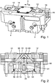
- the Figure 1 shows a gripping device 2 designed as a parallel gripper.
- This comprises a basic housing 4 with a jaw guide 8 running in the clamping direction 6 for gripper jaws 10, 12, which can be inserted into the jaw guide 8 in the clamping direction 6 and are mounted in and extendable therein.
- the clamping direction 6 also corresponds to the longitudinal direction 6.
- On the upper sides of the gripper jaws 10, 12 there are mounting openings 14 for the releasable attachment of Claw finger elements are provided in the broadest sense, which will not be described further here.
- the gripper jaws 10, 12 each have guide webs 16 which extend on both sides in the direction of displacement, which are wedge-shaped or trapezoidal with a flattened free end and which engage in guide grooves 18 on the housing side.
- a wedge hook gear is provided for adjusting the gripper jaws 10, 12.
- the wedge hook 22 is transverse to the clamping direction 6 along a guide axis 20 which in the Figures 2 and 3 can be clearly seen, driven.
- the wedge hook 22 comprises two mirror-symmetrically arranged hooks 29 as well as webs 35 located between the hooks 29 in the guide axis 20, each with a web section 31.
- the hooks 29 furthermore each comprise two parallel to one another which run obliquely to the tensioning direction 6 and the guide axis 20 Guide surfaces 26, 33.
- the webs 35 extend from the guide axis 20 to the hook 29.
- the guide surfaces 26, 33 are coupled in motion with a guide groove 30 running parallel thereto such that a displacement of the wedge hook 22 along the guide axis 20 leads to a displacement of the base jaws 10, 12 along the clamping direction 6.
- the hooks 29 and the guide surfaces 26, 33 have - as from Figures 5 and 6 it becomes clear - an extension 43 extending in the direction of the guide axis 21 which is greater than the vertical extension 23 of the web sections 31, so that the hooks 29 each have an extension section 44 extending in the guide axis direction 21 with a vertical extension 45.
- the vertical extension 43 of the hooks 29 is consequently composed of the vertical extensions 23, 45 of the respective web section 31 and the respective extension section 44.
- the wedge hook 22 further comprises a cylindrical actuating section 52 extending around the guide axis 20, the actuating section 52 projecting beyond the extension section 44 in the guide axis direction 21.
- the adjusting section 52 passes through an opening 54 in the bottom of the jaw guide 8 and engages in a cylinder space 56 of the basic housing 2 arranged underneath.
- a piston 58 is arranged at the lower end of the actuating section 52, the piston 58 being displaceably mounted in the cylinder space 56, so that the cylinder space 56 with the piston 58 forms a hydraulic or pneumatic actuating device for the wedge hook 22.
- the actuating section 52 has an outer lateral surface 64 which is designed as a guide and sealing surface and interacts with the complementary surface 66 delimiting the opening 54 on the housing side.
- the extension section 44 projects beyond the free end 68 of the lateral surface 64 facing the web 35 in the direction of the guide axis.
- the outer contours of the guide surfaces 26, 33 running parallel to one another are congruent when viewed in the clamping direction 6 and also perpendicular to the plane of the guide surfaces 26, 33.
- the web 35 is in the range of
- the other guide surface 26 facing the guide axis 20 is integrally formed on the hook 29, so that the inner guide surface 26 comprises spaced mirror-symmetrical guide surface sections 26 ′ and 26 ′′.
- the outer contour of the inner guide surface 26 is consequently interrupted in the area in which the web 35 touches is molded onto the hook 29. Nevertheless, the outer contour of the guide surface 26 is the same as that of the outer guide surface 33.
- the hook 29 is cylindrical and designed as a parallelepiped.
- the web section 31 has an underside 47 running perpendicular to the guide axis 20 in a plane E2, the guide surfaces 26, 33 each having a lower edge 38, 40 with an underside 42 of the hook 29 running perpendicular to the guide axis 20 and the lower edges 38, 40 lie in a plane E3.
- the plane E3 is spaced apart from the plane E2 by an elevation 45.
- the guide surfaces 26, 33 form an upper edge 32, 34 with an upper side 36 of the hook 29 running perpendicular to the guide axis 20.
- the upper edges 32, 34 lie in a common plane E1 running perpendicular to the guide axis.
- the web section 31 also has an upper side 49 which runs in the plane E1.
- the plane E1 is spaced apart from the plane E2 by a distance or the vertical extent 23. Furthermore, the plane E3 is spaced apart from the plane E1 by the vertical extent 43, which is greater than the distance or the vertical extent 23 of the plane E2 from the plane E1.
- the hook 29 thus has an extension section 44 extending downward.
- the ratio V of the distance of the plane E 2 from the plane E 3 to the distance of the plane E 1 from the plane E 3 is in the range from 0.15 to 0.25 and in particular from 0.2.
- the basic housing 2 has two recesses 46 in the area facing the extension section 44 for receiving the respective extension section 44 when the base jaws 10, 12 are retracted.
- the recesses 46 can in particular each be cylindrical and have a rectangular or square base.
- all edges 48, 50 of the hook 29 are rounded, so that rounded regions 37, 39 are formed.
- the hook 29 is integrally formed with the web 35.
- the adjusting section 52 and the piston 58 are fastened to the web 35 by means of a screw connection 60, each of which is designed as a separate component.
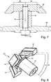
- Figure 8 shows a wedge hook 22 for a centric gripper.
- the wedge hook 22 has three hooks 29 and one web 35 between the respective hook 29 and the guide axis, each with a web section 31, one hook 29 each interacting with a base jaw.
- an undercut 62 is provided, which serves to reduce the notch effect.
- a reduction in the overall height of the gripping device 2 without sacrificing the travel of the base jaws 10, 12 can consequently be achieved in that the entire Elevation of the wedge hook 22 is reduced to a certain extent and the extension section 44 is formed, which has an elevation of exactly this extent.
- the surface pressure can be reduced while the installation space remains the same in that the extension section 44 is formed without reducing the overall extension of the wedge hook 22.
- the contact area between the guide areas 26, 33 can be enlarged, which leads to an advantageous reduction in the surface pressure.
Landscapes
- Engineering & Computer Science (AREA)
- Mechanical Engineering (AREA)
- Robotics (AREA)
- Clamps And Clips (AREA)
- Manipulator (AREA)
Applications Claiming Priority (2)
| Application Number | Priority Date | Filing Date | Title |
|---|---|---|---|
| DE102015218127.8A DE102015218127A1 (de) | 2015-09-22 | 2015-09-22 | Greif- oder Spannvorrichtung |
| PCT/EP2016/070017 WO2017050514A1 (de) | 2015-09-22 | 2016-08-24 | Greif- oder spannvorrichtung |
Publications (2)
| Publication Number | Publication Date |
|---|---|
| EP3352955A1 EP3352955A1 (de) | 2018-08-01 |
| EP3352955B1 true EP3352955B1 (de) | 2020-01-29 |
Family
ID=56853601
Family Applications (1)
| Application Number | Title | Priority Date | Filing Date |
|---|---|---|---|
| EP16760016.2A Active EP3352955B1 (de) | 2015-09-22 | 2016-08-24 | Greif- oder spannvorrichtung |
Country Status (7)
| Country | Link |
|---|---|
| US (1) | US10843311B2 (enExample) |
| EP (1) | EP3352955B1 (enExample) |
| JP (1) | JP7040728B2 (enExample) |
| KR (1) | KR102242887B1 (enExample) |
| CN (1) | CN108025442B (enExample) |
| DE (2) | DE102015218127A1 (enExample) |
| WO (1) | WO2017050514A1 (enExample) |
Families Citing this family (18)
| Publication number | Priority date | Publication date | Assignee | Title |
|---|---|---|---|---|
| US10835964B2 (en) * | 2016-10-05 | 2020-11-17 | Kitagawa Iron Works Co., Ltd | Gripper |
| ES2787881T3 (es) | 2017-02-13 | 2020-10-19 | Smw Autoblok Spannsysteme Gmbh | Dispositivo y carcasa de sujeción |
| JP7064785B2 (ja) * | 2017-06-20 | 2022-05-11 | 株式会社コスメック | 把持装置 |
| CN107598961A (zh) * | 2017-09-28 | 2018-01-19 | 深圳市优必选科技有限公司 | 一种机器人手臂 |
| DE102018003486A1 (de) * | 2018-04-30 | 2019-10-31 | Günther Zimmer | Greifvorrichtung mit optimiertem Doppelschiebekeilglied II |
| CN109333572B (zh) * | 2018-10-25 | 2020-07-28 | 台州市良曜成套设备有限公司 | 一种机械手 |
| TWI811471B (zh) * | 2018-10-26 | 2023-08-11 | 日商北川鐵工所股份有限公司 | 滑動構造體 |
| CN112770877B (zh) * | 2018-10-31 | 2024-07-16 | 株式会社北川铁工所 | 夹具及系统 |
| KR102200040B1 (ko) * | 2019-03-29 | 2021-01-08 | 황규건 | 더블 죠를 구비한 공압 바이스 |
| KR102183454B1 (ko) * | 2019-03-29 | 2020-11-26 | 황규건 | 트리플 죠를 구비한 공압 바이스 |
| KR102326880B1 (ko) * | 2019-07-12 | 2021-11-16 | 주식회사 로보스타 | 그리퍼 |
| CN110860882B (zh) * | 2020-01-14 | 2021-08-27 | 珠海迈超智能装备有限公司 | 灯带夹持推送机构以及灯带穿线机 |
| KR102251923B1 (ko) * | 2020-03-31 | 2021-05-14 | 유에 다르 인더스트리 컴퍼니 리미티드 | 자동 위치고정 정밀 공기 유압 클램핑 고정구 |
| JP7810521B2 (ja) | 2021-02-18 | 2026-02-03 | Smc株式会社 | 開閉チャックおよびそのフィンガの製造方法 |
| CN117769486A (zh) * | 2021-05-24 | 2024-03-26 | 戴弗根特技术有限公司 | 机器人夹持器设备 |
| KR102733988B1 (ko) * | 2022-09-02 | 2024-11-25 | 디사이노 주식회사 | 반도체 웨이퍼 트레이 지그장치 |
| JP2025029330A (ja) * | 2023-08-21 | 2025-03-06 | 株式会社コスメック | 把持装置 |
| CN119927659B (zh) * | 2025-03-17 | 2026-03-27 | 苏州澜力重工集团有限公司 | 一种钢结构加工用开槽装置 |
Family Cites Families (12)
| Publication number | Priority date | Publication date | Assignee | Title |
|---|---|---|---|---|
| DE3338898A1 (de) * | 1983-10-27 | 1985-05-15 | Cushman Industries, Inc., Hartford, Conn. | Keilspannfutter |
| DE3736148A1 (de) | 1987-10-26 | 1989-05-03 | Mader Gmbh | Greifvorrichtung |
| DE19604649C2 (de) * | 1996-02-09 | 1998-10-15 | Schunk Fritz Gmbh | Greifvorrichtung bzw. Spannvorrichtung |
| ATE311962T1 (de) * | 2000-03-15 | 2005-12-15 | Schunk Gmbh & Co Kg | Parallelgreifer |
| DE10049070C2 (de) * | 2000-10-02 | 2002-10-24 | Schunk Gmbh & Co Kg | Kraftspannfutter |
| DE20105449U1 (de) * | 2001-03-28 | 2001-08-09 | FESTO AG & Co., 73734 Esslingen | Fluidbetätigter Greifer |
| JP4737456B2 (ja) | 2007-11-22 | 2011-08-03 | Smc株式会社 | グリッパ機構 |
| US8152214B2 (en) * | 2008-09-04 | 2012-04-10 | Phd, Inc. | Gripper with self-compensating jaw guides |
| DE202011103200U1 (de) | 2011-06-29 | 2012-07-04 | Schunk Gmbh & Co. Kg Spann- Und Greiftechnik | Spann- oder Greifeinrichtung |
| DE102013019034B4 (de) * | 2013-11-15 | 2019-05-09 | Günther Zimmer | Greifvorrichtung mit separaten Führungsschienen |
| DE102013020490B4 (de) * | 2013-12-11 | 2018-10-11 | Günther Zimmer | Antriebsvorrichtung für eine Greifvorrichtung |
| CH709351A1 (de) * | 2014-03-11 | 2015-09-15 | Erowa Ag | Kupplungsvorrichtung für ein Handhabungsgerät. |
-
2015
- 2015-09-22 DE DE102015218127.8A patent/DE102015218127A1/de not_active Ceased
-
2016
- 2016-08-24 KR KR1020187010171A patent/KR102242887B1/ko active Active
- 2016-08-24 DE DE202016008780.1U patent/DE202016008780U1/de active Active
- 2016-08-24 US US15/762,000 patent/US10843311B2/en active Active
- 2016-08-24 CN CN201680055353.9A patent/CN108025442B/zh active Active
- 2016-08-24 JP JP2018534002A patent/JP7040728B2/ja active Active
- 2016-08-24 WO PCT/EP2016/070017 patent/WO2017050514A1/de not_active Ceased
- 2016-08-24 EP EP16760016.2A patent/EP3352955B1/de active Active
Non-Patent Citations (1)
| Title |
|---|
| None * |
Also Published As
| Publication number | Publication date |
|---|---|
| JP7040728B2 (ja) | 2022-03-23 |
| EP3352955A1 (de) | 2018-08-01 |
| JP2018527210A (ja) | 2018-09-20 |
| CN108025442B (zh) | 2021-07-09 |
| US10843311B2 (en) | 2020-11-24 |
| DE102015218127A1 (de) | 2017-03-23 |
| US20180290267A1 (en) | 2018-10-11 |
| CN108025442A (zh) | 2018-05-11 |
| WO2017050514A1 (de) | 2017-03-30 |
| DE202016008780U1 (de) | 2019-08-21 |
| KR20180056672A (ko) | 2018-05-29 |
| KR102242887B1 (ko) | 2021-04-21 |
Similar Documents
| Publication | Publication Date | Title |
|---|---|---|
| EP3352955B1 (de) | Greif- oder spannvorrichtung | |
| DE102015101306B4 (de) | Öffnungs- und Schließspanner | |
| DE3807786A1 (de) | Kolbenstangenloser zylinder | |
| DE29706098U1 (de) | Schlitten-Antriebsvorrichtung | |
| DE102019219588A1 (de) | Befestigungsvorrichtung und Tisch mit einer solchen Befestigungsvorrichtung | |
| EP3653821A1 (de) | Führungsvorrichtung | |
| EP0958109B1 (de) | Greifvorrichtung | |
| EP3353427B1 (de) | Automationskomponente oder spannvorrichtung mit einem kolben | |
| DE102007050353B4 (de) | Greifvorrichtung | |
| DE102012211438B4 (de) | Befestigungseinrichtung zum Befestigen von Zubehörteilen an medizinischen Einrichtungen | |
| EP1616659A2 (de) | Linearantrieb mit einem von zwei Führungseinheiten flankierten Schlitten | |
| DE69801831T2 (de) | Spreizvorrichtung | |
| DE202006004889U1 (de) | Hebevorrichtung | |
| DE102014102993B4 (de) | Werkzeugschieber | |
| EP2998068A1 (de) | Zentrumsspanner mit schnellwechselbacken | |
| DE102014102626A1 (de) | Kettenglied für eine Energieführungskette | |
| EP4105432B1 (de) | Automatische dichtung mit einem führungselement zum führen einer schubstange und verfahren zum positionieren des führungselementes in einem gehäuse der dichtung | |
| EP0997655A1 (de) | Linearführung | |
| DE102013215766B4 (de) | Arretierbolzen-Anordnung mit Drehbetätiger | |
| EP1574283A1 (de) | Linearantrieb mit besonderer Ausführung von Anschlägen zur Hubbegrenzung des Schlittens | |
| DE3125384C2 (enExample) | ||
| DE7223493U (de) | Haltevorrichtung mit Halteklammern | |
| EP2995502A1 (de) | Dachträgeranordnung für ein kraftfahrzeug | |
| DE102012009296A1 (de) | Teleskopschienenführung | |
| DE202007009889U1 (de) | Sensorelement und Klemmhilfsglied zur Halterung des Sensorelementes in einer unterschnittene Wände aufweisenden Nut |
Legal Events
| Date | Code | Title | Description |
|---|---|---|---|
| REG | Reference to a national code |
Ref country code: DE Ref legal event code: R138 Ref document number: 202016008780 Country of ref document: DE Free format text: GERMAN DOCUMENT NUMBER IS 502016008559 |
|
| STAA | Information on the status of an ep patent application or granted ep patent |
Free format text: STATUS: THE INTERNATIONAL PUBLICATION HAS BEEN MADE |
|
| PUAI | Public reference made under article 153(3) epc to a published international application that has entered the european phase |
Free format text: ORIGINAL CODE: 0009012 |
|
| STAA | Information on the status of an ep patent application or granted ep patent |
Free format text: STATUS: REQUEST FOR EXAMINATION WAS MADE |
|
| 17P | Request for examination filed |
Effective date: 20180221 |
|
| AK | Designated contracting states |
Kind code of ref document: A1 Designated state(s): AL AT BE BG CH CY CZ DE DK EE ES FI FR GB GR HR HU IE IS IT LI LT LU LV MC MK MT NL NO PL PT RO RS SE SI SK SM TR |
|
| AX | Request for extension of the european patent |
Extension state: BA ME |
|
| DAV | Request for validation of the european patent (deleted) | ||
| DAX | Request for extension of the european patent (deleted) | ||
| GRAP | Despatch of communication of intention to grant a patent |
Free format text: ORIGINAL CODE: EPIDOSNIGR1 |
|
| STAA | Information on the status of an ep patent application or granted ep patent |
Free format text: STATUS: GRANT OF PATENT IS INTENDED |
|
| INTG | Intention to grant announced |
Effective date: 20190927 |
|
| RAP1 | Party data changed (applicant data changed or rights of an application transferred) |
Owner name: SCHUNK GMBH & CO. KG SPANN- UND GREIFTECHNIK |
|
| GRAS | Grant fee paid |
Free format text: ORIGINAL CODE: EPIDOSNIGR3 |
|
| GRAA | (expected) grant |
Free format text: ORIGINAL CODE: 0009210 |
|
| STAA | Information on the status of an ep patent application or granted ep patent |
Free format text: STATUS: THE PATENT HAS BEEN GRANTED |
|
| AK | Designated contracting states |
Kind code of ref document: B1 Designated state(s): AL AT BE BG CH CY CZ DE DK EE ES FI FR GB GR HR HU IE IS IT LI LT LU LV MC MK MT NL NO PL PT RO RS SE SI SK SM TR |
|
| REG | Reference to a national code |
Ref country code: GB Ref legal event code: FG4D Free format text: NOT ENGLISH |
|
| REG | Reference to a national code |
Ref country code: CH Ref legal event code: EP |
|
| REG | Reference to a national code |
Ref country code: AT Ref legal event code: REF Ref document number: 1228149 Country of ref document: AT Kind code of ref document: T Effective date: 20200215 |
|
| REG | Reference to a national code |
Ref country code: IE Ref legal event code: FG4D Free format text: LANGUAGE OF EP DOCUMENT: GERMAN |
|
| REG | Reference to a national code |
Ref country code: DE Ref legal event code: R096 Ref document number: 502016008559 Country of ref document: DE |
|
| REG | Reference to a national code |
Ref country code: NL Ref legal event code: MP Effective date: 20200129 |
|
| PG25 | Lapsed in a contracting state [announced via postgrant information from national office to epo] |
Ref country code: NO Free format text: LAPSE BECAUSE OF FAILURE TO SUBMIT A TRANSLATION OF THE DESCRIPTION OR TO PAY THE FEE WITHIN THE PRESCRIBED TIME-LIMIT Effective date: 20200429 Ref country code: FI Free format text: LAPSE BECAUSE OF FAILURE TO SUBMIT A TRANSLATION OF THE DESCRIPTION OR TO PAY THE FEE WITHIN THE PRESCRIBED TIME-LIMIT Effective date: 20200129 Ref country code: RS Free format text: LAPSE BECAUSE OF FAILURE TO SUBMIT A TRANSLATION OF THE DESCRIPTION OR TO PAY THE FEE WITHIN THE PRESCRIBED TIME-LIMIT Effective date: 20200129 Ref country code: PT Free format text: LAPSE BECAUSE OF FAILURE TO SUBMIT A TRANSLATION OF THE DESCRIPTION OR TO PAY THE FEE WITHIN THE PRESCRIBED TIME-LIMIT Effective date: 20200621 |
|
| REG | Reference to a national code |
Ref country code: LT Ref legal event code: MG4D |
|
| PG25 | Lapsed in a contracting state [announced via postgrant information from national office to epo] |
Ref country code: HR Free format text: LAPSE BECAUSE OF FAILURE TO SUBMIT A TRANSLATION OF THE DESCRIPTION OR TO PAY THE FEE WITHIN THE PRESCRIBED TIME-LIMIT Effective date: 20200129 Ref country code: SE Free format text: LAPSE BECAUSE OF FAILURE TO SUBMIT A TRANSLATION OF THE DESCRIPTION OR TO PAY THE FEE WITHIN THE PRESCRIBED TIME-LIMIT Effective date: 20200129 Ref country code: LV Free format text: LAPSE BECAUSE OF FAILURE TO SUBMIT A TRANSLATION OF THE DESCRIPTION OR TO PAY THE FEE WITHIN THE PRESCRIBED TIME-LIMIT Effective date: 20200129 Ref country code: IS Free format text: LAPSE BECAUSE OF FAILURE TO SUBMIT A TRANSLATION OF THE DESCRIPTION OR TO PAY THE FEE WITHIN THE PRESCRIBED TIME-LIMIT Effective date: 20200529 Ref country code: BG Free format text: LAPSE BECAUSE OF FAILURE TO SUBMIT A TRANSLATION OF THE DESCRIPTION OR TO PAY THE FEE WITHIN THE PRESCRIBED TIME-LIMIT Effective date: 20200429 Ref country code: GR Free format text: LAPSE BECAUSE OF FAILURE TO SUBMIT A TRANSLATION OF THE DESCRIPTION OR TO PAY THE FEE WITHIN THE PRESCRIBED TIME-LIMIT Effective date: 20200430 |
|
| PG25 | Lapsed in a contracting state [announced via postgrant information from national office to epo] |
Ref country code: NL Free format text: LAPSE BECAUSE OF FAILURE TO SUBMIT A TRANSLATION OF THE DESCRIPTION OR TO PAY THE FEE WITHIN THE PRESCRIBED TIME-LIMIT Effective date: 20200129 |
|
| PG25 | Lapsed in a contracting state [announced via postgrant information from national office to epo] |
Ref country code: CZ Free format text: LAPSE BECAUSE OF FAILURE TO SUBMIT A TRANSLATION OF THE DESCRIPTION OR TO PAY THE FEE WITHIN THE PRESCRIBED TIME-LIMIT Effective date: 20200129 Ref country code: ES Free format text: LAPSE BECAUSE OF FAILURE TO SUBMIT A TRANSLATION OF THE DESCRIPTION OR TO PAY THE FEE WITHIN THE PRESCRIBED TIME-LIMIT Effective date: 20200129 Ref country code: SK Free format text: LAPSE BECAUSE OF FAILURE TO SUBMIT A TRANSLATION OF THE DESCRIPTION OR TO PAY THE FEE WITHIN THE PRESCRIBED TIME-LIMIT Effective date: 20200129 Ref country code: EE Free format text: LAPSE BECAUSE OF FAILURE TO SUBMIT A TRANSLATION OF THE DESCRIPTION OR TO PAY THE FEE WITHIN THE PRESCRIBED TIME-LIMIT Effective date: 20200129 Ref country code: LT Free format text: LAPSE BECAUSE OF FAILURE TO SUBMIT A TRANSLATION OF THE DESCRIPTION OR TO PAY THE FEE WITHIN THE PRESCRIBED TIME-LIMIT Effective date: 20200129 Ref country code: SM Free format text: LAPSE BECAUSE OF FAILURE TO SUBMIT A TRANSLATION OF THE DESCRIPTION OR TO PAY THE FEE WITHIN THE PRESCRIBED TIME-LIMIT Effective date: 20200129 Ref country code: DK Free format text: LAPSE BECAUSE OF FAILURE TO SUBMIT A TRANSLATION OF THE DESCRIPTION OR TO PAY THE FEE WITHIN THE PRESCRIBED TIME-LIMIT Effective date: 20200129 Ref country code: RO Free format text: LAPSE BECAUSE OF FAILURE TO SUBMIT A TRANSLATION OF THE DESCRIPTION OR TO PAY THE FEE WITHIN THE PRESCRIBED TIME-LIMIT Effective date: 20200129 |
|
| REG | Reference to a national code |
Ref country code: DE Ref legal event code: R097 Ref document number: 502016008559 Country of ref document: DE |
|
| PLBE | No opposition filed within time limit |
Free format text: ORIGINAL CODE: 0009261 |
|
| STAA | Information on the status of an ep patent application or granted ep patent |
Free format text: STATUS: NO OPPOSITION FILED WITHIN TIME LIMIT |
|
| 26N | No opposition filed |
Effective date: 20201030 |
|
| PG25 | Lapsed in a contracting state [announced via postgrant information from national office to epo] |
Ref country code: PL Free format text: LAPSE BECAUSE OF FAILURE TO SUBMIT A TRANSLATION OF THE DESCRIPTION OR TO PAY THE FEE WITHIN THE PRESCRIBED TIME-LIMIT Effective date: 20200129 Ref country code: SI Free format text: LAPSE BECAUSE OF FAILURE TO SUBMIT A TRANSLATION OF THE DESCRIPTION OR TO PAY THE FEE WITHIN THE PRESCRIBED TIME-LIMIT Effective date: 20200129 |
|
| PG25 | Lapsed in a contracting state [announced via postgrant information from national office to epo] |
Ref country code: MC Free format text: LAPSE BECAUSE OF FAILURE TO SUBMIT A TRANSLATION OF THE DESCRIPTION OR TO PAY THE FEE WITHIN THE PRESCRIBED TIME-LIMIT Effective date: 20200129 |
|
| GBPC | Gb: european patent ceased through non-payment of renewal fee |
Effective date: 20200824 |
|
| PG25 | Lapsed in a contracting state [announced via postgrant information from national office to epo] |
Ref country code: LU Free format text: LAPSE BECAUSE OF NON-PAYMENT OF DUE FEES Effective date: 20200824 |
|
| REG | Reference to a national code |
Ref country code: BE Ref legal event code: MM Effective date: 20200831 |
|
| PG25 | Lapsed in a contracting state [announced via postgrant information from national office to epo] |
Ref country code: IE Free format text: LAPSE BECAUSE OF NON-PAYMENT OF DUE FEES Effective date: 20200824 Ref country code: GB Free format text: LAPSE BECAUSE OF NON-PAYMENT OF DUE FEES Effective date: 20200824 Ref country code: BE Free format text: LAPSE BECAUSE OF NON-PAYMENT OF DUE FEES Effective date: 20200831 |
|
| PG25 | Lapsed in a contracting state [announced via postgrant information from national office to epo] |
Ref country code: TR Free format text: LAPSE BECAUSE OF FAILURE TO SUBMIT A TRANSLATION OF THE DESCRIPTION OR TO PAY THE FEE WITHIN THE PRESCRIBED TIME-LIMIT Effective date: 20200129 Ref country code: MT Free format text: LAPSE BECAUSE OF FAILURE TO SUBMIT A TRANSLATION OF THE DESCRIPTION OR TO PAY THE FEE WITHIN THE PRESCRIBED TIME-LIMIT Effective date: 20200129 Ref country code: CY Free format text: LAPSE BECAUSE OF FAILURE TO SUBMIT A TRANSLATION OF THE DESCRIPTION OR TO PAY THE FEE WITHIN THE PRESCRIBED TIME-LIMIT Effective date: 20200129 |
|
| PG25 | Lapsed in a contracting state [announced via postgrant information from national office to epo] |
Ref country code: MK Free format text: LAPSE BECAUSE OF FAILURE TO SUBMIT A TRANSLATION OF THE DESCRIPTION OR TO PAY THE FEE WITHIN THE PRESCRIBED TIME-LIMIT Effective date: 20200129 Ref country code: AL Free format text: LAPSE BECAUSE OF FAILURE TO SUBMIT A TRANSLATION OF THE DESCRIPTION OR TO PAY THE FEE WITHIN THE PRESCRIBED TIME-LIMIT Effective date: 20200129 |
|
| REG | Reference to a national code |
Ref country code: AT Ref legal event code: MM01 Ref document number: 1228149 Country of ref document: AT Kind code of ref document: T Effective date: 20210824 |
|
| PG25 | Lapsed in a contracting state [announced via postgrant information from national office to epo] |
Ref country code: AT Free format text: LAPSE BECAUSE OF NON-PAYMENT OF DUE FEES Effective date: 20210824 |
|
| P01 | Opt-out of the competence of the unified patent court (upc) registered |
Effective date: 20230628 |
|
| PGFP | Annual fee paid to national office [announced via postgrant information from national office to epo] |
Ref country code: DE Payment date: 20250820 Year of fee payment: 10 |
|
| PGFP | Annual fee paid to national office [announced via postgrant information from national office to epo] |
Ref country code: IT Payment date: 20250825 Year of fee payment: 10 |
|
| PGFP | Annual fee paid to national office [announced via postgrant information from national office to epo] |
Ref country code: FR Payment date: 20250828 Year of fee payment: 10 |
|
| PGFP | Annual fee paid to national office [announced via postgrant information from national office to epo] |
Ref country code: CH Payment date: 20250901 Year of fee payment: 10 |